Missouri University of Science and Technology Missouri University of Science and Technology Scholars' Mine Scholars' Mine UMR-MEC Conference on Energy 13 Oct 1976 A Solar Energy System for Domestic Hot Water A Solar Energy System for Domestic Hot Water Thomas J. McNamara Follow this and additional works at: https://scholarsmine.mst.edu/umr-mec Part of the Chemical Engineering Commons, and the Energy Policy Commons Recommended Citation Recommended Citation McNamara, Thomas J., "A Solar Energy System for Domestic Hot Water" (1976). UMR-MEC Conference on Energy. 154. https://scholarsmine.mst.edu/umr-mec/154 This Article - Conference proceedings is brought to you for free and open access by Scholars' Mine. It has been accepted for inclusion in UMR-MEC Conference on Energy by an authorized administrator of Scholars' Mine. This work is protected by U. S. Copyright Law. Unauthorized use including reproduction for redistribution requires the permission of the copyright holder. For more information, please contact [email protected].
Transcript
Missouri University of Science and Technology Missouri University of Science and Technology
Scholars' Mine Scholars' Mine
UMR-MEC Conference on Energy
13 Oct 1976
A Solar Energy System for Domestic Hot Water A Solar Energy System for Domestic Hot Water
Thomas J. McNamara
Follow this and additional works at: https://scholarsmine.mst.edu/umr-mec
Part of the Chemical Engineering Commons, and the Energy Policy Commons
Recommended Citation Recommended Citation McNamara, Thomas J., "A Solar Energy System for Domestic Hot Water" (1976). UMR-MEC Conference on Energy. 154. https://scholarsmine.mst.edu/umr-mec/154
This Article - Conference proceedings is brought to you for free and open access by Scholars' Mine. It has been accepted for inclusion in UMR-MEC Conference on Energy by an authorized administrator of Scholars' Mine. This work is protected by U. S. Copyright Law. Unauthorized use including reproduction for redistribution requires the permission of the copyright holder. For more information, please contact [email protected].
AbstractTo help reduce natural gas consumption and operating costs a domestic hot water heating solar energy system is to be retrofitted and integrated into the existing conventional mechanical systems. This installation would not only provide substantial fuel cost savings to the Museum, but it would also provide a means of showing and explaining the operation of an actual working solar energy system to the large number of daily visitors to the Museum. This report explains the design, operation and performance of that solar energy system.
D
1. INTRODUCTION
1.1The Museum of Science- and Industry has a primary goal to show how science and industry have contributed to the American way of life. They feel that by adding a viable practical, solar energy hot water heating system to their own building they will better fulfill their goal and at the same time they will also: (1) reduce their fossil fuel consumption and their operating cost; (2) reduce air and thermal pollution because solar is "clean" energy which has no products of combustion such as hot flue gases with entrained pollutants; and (3) provide a viable demonstration to the public of the practical use of solar energy as an alternative energy source to the diminishing oil and natural gas energy resources. This project also demonstrates that the technology and "know-how" exist, which are needed to make use of solar energy in a commercial application.
1.2If solar energy can be applied to help heat the large quantities of domestic hot water used each day by the visitors to the Museum, it would significantly reduce their natural gas consumption and operating cost.
2. PROJECT INFORMATION
2.1The Museum is an existing three-story building which is the restored fine arts building from the World's Columbian Exposition of 1893 which was opened in 1933 at the time of the Century of Progress Exposition in Chicago. It is considered one of the finest examples of classic Greek architecture. The building covers approximately 14 acres. The Museum of Science and Industry is located in Chicago, Illinois, approximately 6 miles south of the downtown business district and adjacent to the scenic shoreline of Lake Michigan. The floor plan is shown in Fi gure 2 .
3 . THE SOLAR ENERGY SYSTEM
3.1The solar energy system proposed will heat hot’ water to meet the consistently large daily hot water quantities used by an average of approximately 10,000 visitors to the Museum. This large number of visitors to the Museum occurs on every day of the year except Christmas Day, the only day it is closed.3.2In order to conserve energy by reducing fossil fuel consumption and to reduce operating cost, a retrofit solar system installation of initially 15,000 square feet of the Model P5 General Electric flat
427
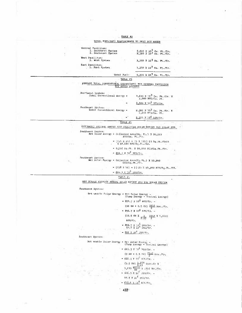
plate solar collector installed on the south half on the flat roof southeast and southwest areas of the central pavilion building of the Museum of Science and Industry (See Fig. 2). The solar energy system will consist of: the arrays of solar collector panels, energy storage tanks, pumps, heat exchangers, interconnecting piping, controls, thermal insulation and monitoring instrumentation. The solar energy system will supplement the existing two hot water heaters: (1) located in the north ground floor equipment room; and (2) located in the south equipment room on the ground floor. A water/ethylene glycol anti-freeze solution is circulated through the collectors and then to a heat exchanger. The heat exchanger, pumps, thermal energy storage tanks, systems valves, and controls are located in the equipment areas on the ground floor. From this area the heat is supplied to the heat exchanger to heat hot water for use in the toilet rooms and janitor closets throughout the central pavilion buildings. See Fig.
3.3The two (2) thermal energy storage tanks each have a capacity of 1,000 gallons and are used to store excess solar energy for use during periods when direct collection is insufficient to supply the hot water demand. This installation was designed to provide approximately 21% of the total heat required to heat hot water for the central pavilion building daily demands. 4
4. SOLAR SYSTEM CONTROL AND INSTRUMENTATION
4.1 SYSTEM CONTROL4.1.1A flexible, adjustable control system is provided for the solar energy system to allow for variations in operating modes. Control and modulating valves are provided and integrated with the existing hot water system, making use of existing manual and automatic controls to regulate hot water supplied by the solar energy system. This interface is established so that hat water can be supplied from either or both systems to meet hot water load demands. The basic control functions are operated from a self-contained panel. The system is designed for automatic operation with monitoring by regular maintenance personnel. Following is Table # l which describes the solar system operating modes. Please refer also to Fig. #1.
4.1.2The control subsystem for the solar hot water heating system adheres to standard commercial practices as defined and presented in the ASHRAE Handbook. Electromechanical logic is employed to control the operation of four pumps, two proportional three-way valves and four two-way valve s.
4.1.3The system schematic diagram Fig. #1 is typical and representative of the control arrangement for the southwest and the southeast system. The collector loop absorbs solar energy from the collector plates and delivers this energy to the heat exchanger. The therma-1 storage/usage loop stores thermal energy in a fluid tank to provide hot water heating.4.1.4The five major system operating modes have been described in Table # 1 together with their corresponding mechanical component functions. Mode 1 defines the case for which no solar or stored energy is available. Mode 1 corresponds to the case in which the building's conventional hot water heating system must be utilized.
4.1.5In mode 2, no direct solar energy is available; however, stored solar energy can provide the hot water heating functions. As Table # 1 indicates, mode 2 occurs when the collector plate temperature (TC) is below 150°F and the thermal storage tank (T3) temperature is above 150°F.4.1.6Temperature sensor TI controls the three- way diverting valve V-I to increase flow from thermal energy storage as temperature begins to drop.
4.1.7Temperature sensor T3 will shut off pump P2 when temperature falls below 150°F as long as solar collector temperature sensor (TC) is also below 150°F. When TC is above 150°F it starts pumps PI and P2.
4.1.8Mode 3 transfers solar energy directly from the collector loop to the hot water heater when thermal energy storage (T3) is below 150° F.
428
4.1.9Mode 4 Is the normal daytime hot water heating and storing operation. Sufficient energy is available to heat the water needed by demand and also to store energy In the thermal storage tank.4.1.10Mode 5 is a safety operation. When the thermal energy storage tank rises to 210°F a thermal switch closes. This energizes valve V-2 (open) in the domestic hot water outlet and also energizes valve V-3 (closed) in the steam supply line to the hot water heater.4.2 SOLAR SYSTEM INSTRUMENTATION4.2.1Instrumentation is provided to monitor system performance and to allow an evaluation of operating parameters. Display and recording capability are provided by an instrumentation console. The instrumentation system is capable of providing data for evaluation of various system operating modes.4.2.2Instrumentation readout and recording equipment is capable of monitoring thirty-eight (38) channels of data. The system has sufficient flexibility built into its basic operating modes so that performance data can be generated over a wide range of off-design conditions.
4.2.3The instrumentation console is located at one end of the visitor's solar energy information and viewing center as shown on Fig. 3 . In addition to the instrumentation console, a solar energy system visual display is installed at the north end of the viewing center in the display area within the glass enclosure and will show on the simulated flow display the operation of the solar energy system while a taped description about the solar energy system, its operation and purpose will emanate from the ceiling speakers explaining to each of the thousands of daily Museum visitors the operating principles, statistics, cost savings and other benefits of this solar energy system. 5
5. SOLAR COLLECTOR ARRAYS AND LOOPS
5.1There are two arrays. The southwest array has 372 collectors divided into two
banks - A and B - and the southeast array has 290 collectors divided into two banks - C and D, Fig. 3 . Each bank has a separate fluid loop with inlet headers on the inner edge of the rows and returns arranged in reverse return on the outer edges. The solar collectors are mounted on a lightweight structural grid attached to the existing structural system by penetrating the roof at various support points. They are mounted in rows with their long side horizontal. Clearance is provided under the structure to allow access for roof maintenance. Walkways are provided for access to the collector array.5.2The collectors in each row are interconnected at the corners with rubber hoses clamped to elbows we.lded to integral inlet and outlet headers. This provides parallel flow through each collector row, with cool water entering at the bottom of each collector, being heated as it rises through serpentine fluid passages and exiting at top.
5.3The mechanical system consists of a solar collector loop, a heating and storage loop, mechanical equipment such as pumps, heat exchangers and filters, thermal energy storage tanks, and interconnecting piping and valves whose general arrangement is shown in Fig. 1.
5.4
The solar collector loop transfers the energy collected by the solar array to a heat exchanger. It consists physically of the headers and mains connected to the collectors on the roof, 3 inch/4 inch mains running down a piping shaft to ground floor equipment rooms, 7-1/2 (PI) and 5 (P2) horsepower pumps, and the tube side of the heat exchangers with total surface areas of 300 square feet each.5.5See Tbl.#7 fo r nominal operating conditions o f the pumps.
5.6.See Tbl.#8 for heat exchangers nominal operating parameters.
5.7The hot water heating and storage loop contains the pump, valves, filters and interconnecting piping for all system components downstream of the main collector heat exchanger. This loop uses a five
429
horsepower pump under the operating conditions outlined in Table # 9 .
5.8Thermal energy stdrage is provided by2,000 gallons of water stored In two cylindrical tanks. The tanks are 48 inches in diameter by approximately 90 inches long. A 24 inch diameter manhole is located in one end of each tank with flanges and bosses on the ends for piping and instrumentation. The tanks are located in the mechanical equipment areas. They are mounted horizontally on saddles. The tanks are insulated on all sides with four inches of foamglass insulation.
5.9All electrical power originates from the mechanical equipment area. The 208 volt three-phase power is supplied to the pumps through motor starter units switched from the control panel. The 120 volt power supplies the control panel power supply which provides appropriate voltages to the control circuits and logic. The three motorized valves in each system are actuated by 24 volt control circuits and operated by 120 volt motors. The Instrumentation console in the visitor's observation center adjacent to the roof area is powered by a separate 120 volt circuit. All system operating power is monitored by a watt-hour meter.
5.10The instrumentation console was incorporated Into the system to monitor performance and obtain diagnostic information.It Is completely independent of the system and Is not needed for system operation. Instrumentation is provided to analyze system performance and operation.
6. SOLAR COLLECTOR PHYSICAL DATA
6.1The solar collectors are 3 x 8 foot flat plate, medium-temperature, high efficiency units.6.2The collector has four major components, the frame, insulation, absorber plate and cover window. The frame is a welded aluminum extrusion with a 0.030 inch aluminum backer sheet bonded to the frame to form a pan. The aluminum extrusion frame is made purposely with a smooth thickwalled structural web to give the user a good selection of mounting techniques. The overall chassis design
will withstand windloads in excess of 100.The collector is equipped with a single non-breakable lexan window.
7. SOLAR SYSTEM PERFORMANCE
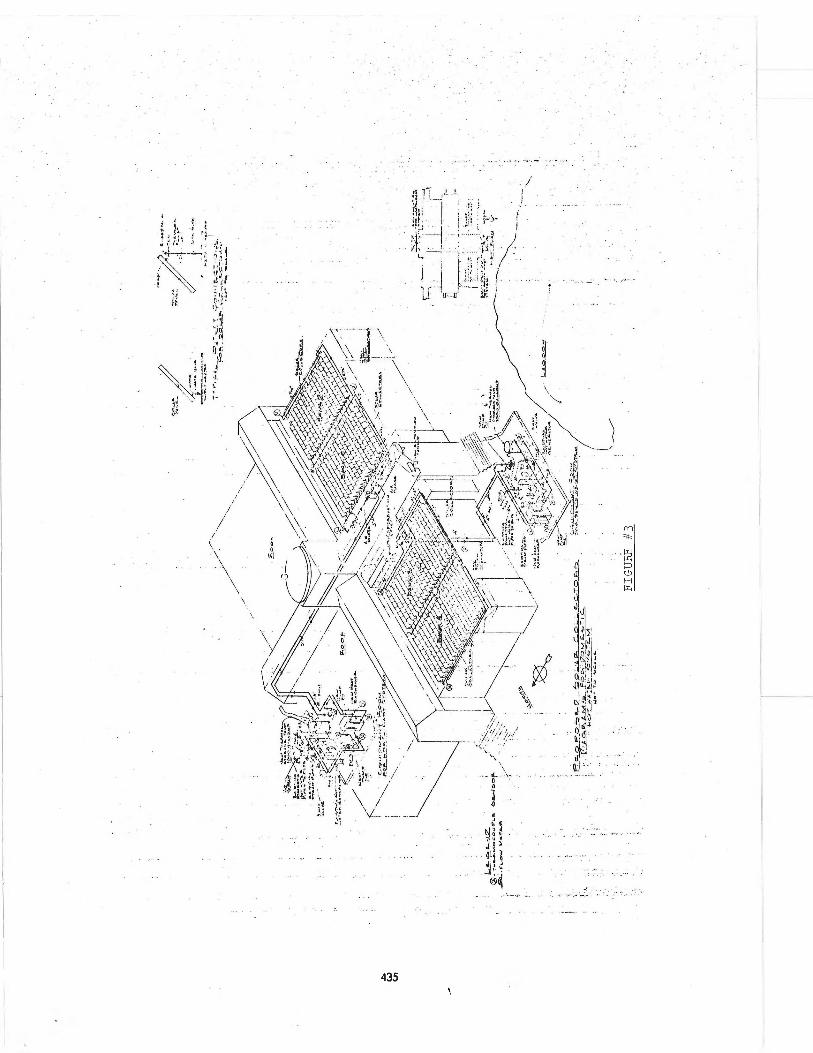
7-1For the estimated annual fuel (cubic feet of gas) requirements for the Museum of Science and Industry see Fig. #4.7.2The Museum currently uses approximately42,500 x 10^ cubic feet of natural gas fuel per year for their total requirements for space heating, heating hot water, kitchen, cooking and laundry. Of this total amount, approximately 2 2% (9,200 x 103 cubic feet) is used to heat domestic hot water used by the visitors (approximately 10,000 per day) and employees (approximately 420) in the public washrooms, employee washrooms, employee locker rooms, and janitor closets.
7-3The daily demand occurs during the hours of 9:30 a.m. and 5=30 p.m. during the summer (during Daylight Saving Time) and during the 9:30 a.m. to 4:00 p.m. period during the winter (during Central Standard Time). The peak demand period each day occurs from about 11:00 a.m. until about 2:00 p.m. because of the lunch period. However, there is a very short period of approximately an hour or less of somewhat reduced demand after which the demand increases back up toward the peak level while visitors and employees again use facilities prior to departure. The demand dramatically drops to nothing, or course, as soon as the Museum closes.
7.4Therefore, analyzing the hot water load demand characteristics, it is seen that there is a relatively large demand beginning shortly after the Museum opens. This demand fluctuates only about 10% up or down after the initial build-up in the morning until the total drop off at closing time. Because of the consistent large demand between the hours of 11:00 a.m. and 5:00 p.m., a relatively small storage capacity (1,000 gallons) for each the southwest and southeast solar hot water systems Is needed. This load also parallels rather closely the period during each day when maximum insolation occurs. Therefore, it is possible to make maximum use of the solar energy as it is being collected to heat water which further tends to reduce the thermal storage capacity requirements. Furthermore, the fact that the Museum is
430
open seven days a week, every day except Christmas, throughout the year presents a continually repeating daily hot water load demand with no extended periods over the weekends or holidays when the demand drops off as would otherwise occur with any average type of commercial application wherein the facility normally closes down over weekends and holidays.7.5Average total fuel (gas) requirements to heat hot water are given in Table #2.
7.6The average total conventional energy(BTU) requirements for central pavillion systems (which will be interfaced with retrofitted solar energy system) are given in Table # 3.
7.7Based on manufacturer's (General Electric) performance data for the model P5 collector, the manufacturer estimates that the model P5 collector would produce an average net output of 99,900 BTU/yr/sq.ft. after adjusting for the Chicago conditions as set forth in the Climatic Atlas for the United States and allowing for 45° tilt of collector with horizontal plane.
7.8Therefore, the estimated average annual net collected solar energy for the solar system is given in Table #4.
7.9The net usable average annual solar energy for the solar system is given in Table #5.7.10To determine the estimated percent annual solar energy contribution toward providing the hot water heating energy requirements would be as shown in Table #6.
M OPERATING NODESCOLLECTOR LOOP PUMP CPI)_____
t h e r m a l s r c - ; .LOOP PUMPCPIQ
CONDITIONS
1. MO HEAT AVAILABLE FROM SOLAR ARRAY
2 . USING THERMAL ENERGY STORAGE
3. USING COLLECTOR LOOP HEAT ABOVE. THERMAL ENERGY STORAGE TEMP.
U . USING AND STORING HEAT
HEAT DUMP
COLLECTOR TEMPERATURE 3ELOW 15C °F AND THERMAL ENERGY STORAGE ( T 3 ) BELOW 1 5 0 ° F
COLLECTOR BELOW 1 30 0 F AND THERMAL ENERGY STORAGE ( T 3 ) ABOVE 1 5 0 0 F
COLLECTOR ABOVE ] 5 0 ° F THERMAL ENERGY
■STORAGE ( T 3 ) BELOW 1 5 0 ° F
fCOLLECTOR ( T C ) ABOVE 1 5 0 ° F , THERMAL ENERGY STORAGE ( T 3 ) 'ABOVE m 0 ° F
•THERMAL ENERGY STORAGE C T 2 ) ABOVE 2 10 ° F
OFF
“ ON :
ON
ON
ON
\ Y
-J O H-3 ii ai U. Q
££ ->0. UJ if/ Lr\ a . io 1C. i n -t
CLOSED
CLOSED
OPEN
UJ !U O -3tCL C. . > O O l
OPEN
CLOSER
OPEN .
CLOSED
TABLE 1
4 3 1
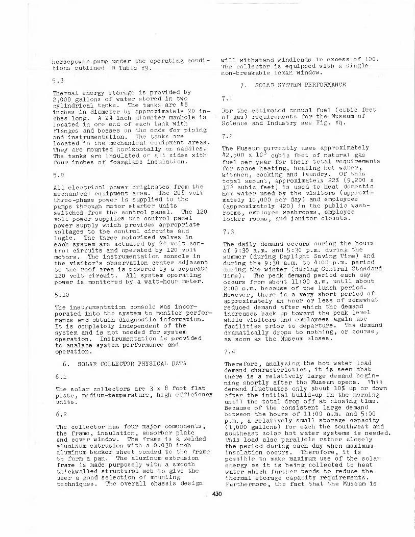
TABLE #2
TOTAL FUEL(GAS) REQUIREMENTS TO HEAT HOT WATER
Central Pavlllion:1. Southwest System2. Southeast System
West Pavlllion:1. West System 1,150 X IO3 Cu. Ft./Yr.
East Pavlllion:. 1. East System 1,150 X 103 Cu. Ft./Yr.
_______________________Total Fuel: 9,200 X IO3 Cu. Ft./Yr.TABLE if 3
AVERAGE TOTAL CONVENTIONAL ENERGY(BTU) FOB CENTRAL PAVILLION HOT WATER SYSTEMS ----------
Southwest System:Total Conventional Energy * * A,600 X 103 Cu. Ft./Yr. X
1.000 BTU/Cu. Ft!ii600 X 10s BTU/Yr.
Southeast System:Total Conventional Energy = 2,300 X 103 Cu. Ft./Yr. X
1.000 BTU/Cu. Ft!2,300 X 1 0 6 BTO/Yr.
TABLE #l|' ■ - " " _ESTIMATED AVERAGE ANNUAL HET COLLECTED SOLAR ENERGY FOB SOLAR SYS. Southwest System:
Net Solar Energy = Collector Area(Sq. Ft.) X 99,900 BTU/Sq. Ft./Yr.
* tan X 15) + (5 x IB)] 23 Eq. Et. /Unit X.99,900 BTU/Sq.Ft./Yr.- ■ ■
- 8,556 Sq.Pt. X 99,900 BTU/Sq.Pt./Yr.- 854.7 X 10⁶ BTU/Yr.
Southeast System:Net Solar Energy = Collector Area(Sq.Ft.) X 99,900
BTU/Sq.Ft./Yr.‘ [(18 X 16) + 2] 23 X 99,900 BTU/Sq.Ft./YR.- 666.3 X 10⁶ BTU/Yr.
TABLE 115
NET USABLE AVERAGE ANNUAL SOLAR ENERGY FOR THE SOLAR SYSTEM
Southwest System:Net usable Solar Energy = Net Solar Energy -
(Pump Energy + Control Energy)- 85/1-7 X 106 BTU/Yr. -(10 KW + 0.5 KW) 2912 Hrs./Yr.
■ 854.7 X IO-6 BTU/YR. -(10.5 KW X _1_ 2912 X 1,000)
0.29 2BTU/Yr.- 854.7 X lof BTU/Yr. -
.52-7 X 10° Btu/Yr.- 802 X 106 BTU/Yr.
Southeast System:Net usable Solar Energy = Net Solar Energy -
(Tump Energy + Control Energy)• 666.3 X 10⁶ BTU/Yr. -
(9 KW + 0.5 KW) 2|12 Hrs./Yr.■ 666-3 X 10⁶ BTU/Yr. -(9 .5 KW) i_|p Watt-Hr X1,000 X 1456 Hr./Yr.
” 6 6 6.3-X-10'6 BTU/Yr. - 47.7 X 1C6 BTU/Yr.
'« 618.6 X 10⁶ BTU/Yr.
4,600 X 103 Cu. Ft./Yr. 2,300 X 10i Cu. Pt./Yr.
' 432
TABLE #6ESTIMATED PERCENT ANNUAL SOLAR ENERGY CONTRIBUTION TOWARD
. HOT WATER HEATING
Solar Energy:Southwest System: 5Net Usable Solar Energy * 802 X 10 BTU/Yr.Southeast System:
Net Usable Solar EnergyTotal Solar Energy
618.6 X 10° BTU/Yr. 1.H20.6 X 106 BTU/Yr.
Energy Requirements Using Conventional System:Southwest System:
Conventional Energy H600 X 10 3 Cu.Ft. X 1,000 BTU 4,600 X 106 BTU/Yr.
Southeast System:Conventional Energy
Total Conventional En'gy=
2.300 X 10³ Cu.Pt. X 1,000 BTU2.300 X 106 BTU/Yr.6.900 X 106 BTU/Yr. ■
Percent Contribution of Solar Energy:. _ v TOTAL NET USABLE SOLAR ENERGYPercent - 10D X .jgjjj CONVENTIONAL ENERGY
■ 100 X 1400.6 X 106 BTU/Yr.5900 X L013 BTU/Yr.
. 100 (0 .21)
= 211
TABLE #1THE NOMTNAT. OPERATING CONDITIONS OP THE PUMPS
PISW SYSTEM
PISE SYSTEM
1. Flow rate 178 GPM 138 GPM
2 . Pressure head 70 to 100 ft. H20 70 to 100 ft. H20
3- Operating fluid 30? ethylene glycol solution
30? ethylene glycol ■ solution
H. Operating temperature 100 to 220°F 100 to 220°F
TABLE #8HEAT EXCHANGERS N( 'ING PARAMETERS
SW SYSTEM SE SYSTEM
1. Loop Delta T
!i 10°F
2. Shell side Delta P 3 ft. 178
H20GPM
@ rated 2.5 ft. H20 138 GPM@ rated
3. Tube side Delta P 9 ft. H20 (§ 178 GPM 8 ft. H20 § 138 GPM
H. Heat transfer rate 750,000 BTU/HR 600,0.00 BTU/HR
5. Shell/tube temp. diff. 0°F 0°F
TABLE £9OPERATING CONDITIONS FOR 5IIP PUMP
P2 (SW)________________P2 (SE)
1 . Flow rate 178 GPM 138 GPM
2. Pressure head H0 to 70 ft. H20 HO to 70 ft. H20
3. Operating fluid water w/ corrosion inhibitors
water w/ corrosion inhibitors
H. Operating, temperature 100 - 210°F -100 - 210° F
433
■ ~1----- H £ . X. P A W S I o M - '.T A U I4 .
] ' J UM-blDE... &OU.171WC,
-Al R- P u E cse ,,6 o u r c o l l e .c t o e .
F l o v J C O W T R - O L" v a l n /e, t o ■pac.'/E.sjf GR.A VIT-T CIK.CUUATION*
60LAP- g-MER&Y SY5TEM FOE. I70ME.6TIC UorMlTEie-P I G tt I
(E-XI-STI KJti Uot WATCJZ.14 E A T E R . W i TU- .
"C .O IL . Am p 6 t « -a m Va l v e . CAUTO - S e l f Ac t lJAT IN<a)
CLout7 Wate.pt j- WAKE, up •-
,----- l j • PM-'i
Tl4e.cz. MocoupLE £-kJ *0 OC2. ;t o Mo t W a t e -RL ' Fix.TiJR.e.i? O U T L.E.T
( . :15v-zk ^
TO pR.Al.KlM E . W T U a R . M A L . _ | bTORAOa 7AM K.”
60HEMATIC FLOW AMP PIPING DIAGRAM ; ___ T y p i c a l f o e , t w o ..;.. 1: -:"......
MOT T o S C A U E .
CHICAGO, Itl .
434
435\
FIGURE #
3
ANNUAL FUEL(GAS) REQUIREMENTS
17, O O P x IO CU.F-17
H e a t i w g
PP 'Q P O j^T I Ok!O F GA-S F U L L R E . Q U I PiE- M E N T 6