Abstract—The objective of this study is to investigate the feasibility of using desiccant cooling system as an alternative HVAC solution in buildings to achieve thermal comfort. This solution is more attractive when the solar energy is used to regenerate the desiccant wheel. An extensive experimental study has been performed in Tohoku University in Japan. A TRNSYS model of the desiccant cooling system combined with the heat wheel and heat source has been simulated and compared with the experimental data. The results of the simulation show that such system is feasible for cooling building in hot-humid climates. Index Terms— Cooling, desiccant wheel, hot-humid climate. I. INTRODUCTION The building sector (commercial and residential) consume large amount of energy to support its operation and maintenance. Moreover, the large part of the energy demand by building is used to support indoor thermal comfort condition. The provision of the building indoor thermal comfort conditions either through heating or cooling is done by the heat pumping system. These devices are called the mechanical vapor compression system [1]. Several researches are conducted to improve the system performance. However, the system still consumes a huge amount of energy. The main energy source of the mechanical vapor compression system is the electric energy from the grid line. In the Middle East, more than 70% of the building energy consumption is to support cooling [2]. In Europe, 10% of the building sector energy consumption is like wise to support cooling demand [3]. In Hong Kong, 45% of the commercial building energy consumption is also for cooling [4]. In Japan, 3% of the building sector energy consumption is for cooling application [5]. It is expected that in tropical countries which are hot and humid, energy demand for cooling and dehumidification is very high [6]. Alternative air-conditioning (AC) system which utilizes alternative materials, process, and energy resources can largely reduce building energy consumption [7,8]. Among the alternative AC systems the desiccant cooling systems which can be operated through direct thermal energy, are important options for building cooling. The desiccant air conditioning system utilizes the Manuscript received December 12, 2012; revised February 17, 2013. This work was supported in part by the SQU Internal Research Project IG/ENG/CAED/11/01. Maatouk Khoukhi is with Sultan Qaboos University, CAE Department, PO Box 33, Al Khoud 123, Sultanate of Oman (e-mail: mkhoukhi@ squ.edu.om). capability of desiccant materials in removing the air moisture content by sorption process. The sorption process (adsorption and absorption) is an interaction between the sorbent and sorbate molecule through intermolecular interaction [1]. Since desiccant materials have low concentration of water content, the air moisture content is attracted to the surface of the desiccant materials due to the moisture vapor pressure difference between the air and the desiccant surface. [1]. In order for the desiccant material to be used again, application of thermal energy is necessary to remove the moisture from the desiccant materials [1]. Fig. 1 shows the basic concept and diagram of the thermally activated desiccant cooling technologies. II. SOLID DESICCANT COOLING PRINCIPLES AND CONCEPT A. Concept and Operation The solid desiccant cooling system is primarily based on the application of solid-based desiccant materials in controlling air moisture content. The sorption mechanism in the solid material is either through absorption or adsorption. Cooling by means of heat recovery, evaporative cooling or other means are applied to the system [1]. The solid desiccant material is the most widely used in desiccant cooling system. This is due to the simple handling of desiccant materials. The desiccant material is typically impregnated to the honeycomb designed wheels or of the cross-flow heat exchangers [1]. OA: outside air, SA: supply air, RA: return air, EA: exhaust air, RegA: regeneration air Fig. 1. Basic concept of the desiccant cooling system. B. Development and Evolution The most common solid desiccant cooling system is composed of two wheels types or called the Munter Cycle shown in Fig.1. This is the basic design of the solid desiccant cooling system. The application of the desiccant wheel as the air dehumidifier has factors to be considered. It has been shown that the performance of the desiccant-based cooling A Study of Desiccant-Based Cooling and Dehumidifying System in Hot-Humid Climate Maatouk Khoukhi 191 DOI: 10.7763/IJMMM.2013.V1.41 International Journal of Materials, Mechanics and Manufacturing, Vol. 1, No. 2, May 2013
Transcript
Abstract—The objective of this study is to investigate the
feasibility of using desiccant cooling system as an alternative
HVAC solution in buildings to achieve thermal comfort. This
solution is more attractive when the solar energy is used to
regenerate the desiccant wheel. An extensive experimental
study has been performed in Tohoku University in Japan. A
TRNSYS model of the desiccant cooling system combined with
the heat wheel and heat source has been simulated and
compared with the experimental data. The results of the
simulation show that such system is feasible for cooling building
in hot-humid climates.
Index Terms— Cooling, desiccant wheel, hot-humid climate.
I. INTRODUCTION
The building sector (commercial and residential) consume
large amount of energy to support its operation and
maintenance. Moreover, the large part of the energy demand
by building is used to support indoor thermal comfort
condition.
The provision of the building indoor thermal comfort
conditions either through heating or cooling is done by the
heat pumping system. These devices are called the
mechanical vapor compression system [1]. Several
researches are conducted to improve the system performance.
However, the system still consumes a huge amount of
energy. The main energy source of the mechanical vapor
compression system is the electric energy from the grid line.
In the Middle East, more than 70% of the building energy
consumption is to support cooling [2]. In Europe, 10% of the
building sector energy consumption is like wise to support
cooling demand [3]. In Hong Kong, 45% of the commercial
building energy consumption is also for cooling [4]. In Japan,
3% of the building sector energy consumption is for cooling
application [5]. It is expected that in tropical countries which
are hot and humid, energy demand for cooling and
dehumidification is very high [6].
Alternative air-conditioning (AC) system which utilizes
alternative materials, process, and energy resources can
largely reduce building energy consumption [7,8]. Among
the alternative AC systems the desiccant cooling systems
which can be operated through direct thermal energy, are
important options for building cooling.
The desiccant air conditioning system utilizes the
Manuscript received December 12, 2012; revised February 17, 2013.
This work was supported in part by the SQU Internal Research Project
IG/ENG/CAED/11/01.
Maatouk Khoukhi is with Sultan Qaboos University, CAE Department,
PO Box 33, Al Khoud 123, Sultanate of Oman (e-mail: mkhoukhi@
squ.edu.om).
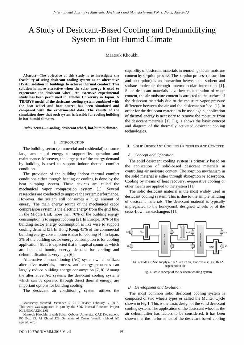
capability of desiccant materials in removing the air moisture
content by sorption process. The sorption process (adsorption
and absorption) is an interaction between the sorbent and
sorbate molecule through intermolecular interaction [1].
Since desiccant materials have low concentration of water
content, the air moisture content is attracted to the surface of
the desiccant materials due to the moisture vapor pressure
difference between the air and the desiccant surface. [1]. In
order for the desiccant material to be used again, application
of thermal energy is necessary to remove the moisture from
the desiccant materials [1]. Fig. 1 shows the basic concept
and diagram of the thermally activated desiccant cooling
technologies.
II. SOLID DESICCANT COOLING PRINCIPLES AND CONCEPT
A. Concept and Operation
The solid desiccant cooling system is primarily based on
the application of solid-based desiccant materials in
controlling air moisture content. The sorption mechanism in
the solid material is either through absorption or adsorption.
Cooling by means of heat recovery, evaporative cooling or
other means are applied to the system [1].
The solid desiccant material is the most widely used in
desiccant cooling system. This is due to the simple handling
of desiccant materials. The desiccant material is typically
impregnated to the honeycomb designed wheels or of the