32
I LL IN S UNIVERSITY OF ILLINOIS AT URBANA-CHAMPAIGN PRODUCTION NOTE University of Illinois at Urbana-Champaign Library Large-scale Digitization Project, 2007.

I LL IN SUNIVERSITY OF ILLINOIS AT URBANA-CHAMPAIGN
PRODUCTION NOTE
University of Illinois atUrbana-Champaign Library
Large-scale Digitization Project, 2007.

UNIVERSITY OF ILLINOIS BULLETINISSUED WEEKLY
Vol. XXIV June 14, 1927 No. 41
[Entered as second-class matter December 11, 1912, at the post office at Urbana, Illinois, underthe Act of August 24, 1912. Acceptance for mailing at the special rate of postage provided
for in section 1103, Act of October 3, 1917, authorized July 31, 1918.]
A STUDY OF FATIGUE CRACKSIN CAR AXLES
A REPORT OF THE INVESTIGATION
CONDUCTED BY
THE ENGINEERING EXPERIMENT STATION
UNIVERSITY OF ILLINOIS
IN CO6PERATION WITH
UTILITIES COOPERATIVE RESEARCH COMMITTEE
BY
HERBERT F. MOORE
BULLETIN NO. 165ENGINEERING EXPERIMENT STATION
PUBISHED BT TH• UNITVES•T OF ILLNOIS, UBANA
PaIcs: FITpEE CENTS

THE Engineering Experiment Station was established byact of the Board of Trustees of the University of Illinoison December 8, 1903. It is the purpose of the Station to
conduct investigations and make studies of importance to theengineering, manufacturing, railway, mining, and other industrialinterests of the State.
The management of the Engineering Experiment Station isvested in an Executive Staff composed of the Director and hisAssistant, the Heads of the several Departments in the Collegeof Engineering, and the Professor of Industrial Chemistry. ThisStaff is responsible for the establishment of general policies gov-erning the work of the Station, including the approval of materialfor publication. All members of the teaching staff of the Collegeare encouraged to engage in scientific research, either directly orin co5peration with the Research Corps composed of full-timeresearch assistants, research graduate assistants, and specialinvestigators.
To render the results of its scientific investigations availableto the public, the Engineering Experiment Station publishes anddistributes a series of bulletins. Occasionally it publishes circu-lars of timely interest, presenting information of importance,compiled from various sources which may not readily be acces-sible to the clientele of the Station.
The volume and number at the top of the front cover pageare merely arbitrary numbers and refer to the general publica-tions of the University. Either above the title or below the sealis given the number of the Engineering Experiment Station bul-letin or circular which should be used in referring to these pub-lications.
For copies of bulletins or circulars or for other informationaddress
THE ENGINEERING EXPERIMENT STATION,UNIVERSITY OF ILLINOIS,
UBBANA, ILLINOIS

UNIVERSITY OF ILLINOISENGINEERING EXPERIMENT STATION
BULLETIN No. 165 JUNE, 1927
A STUDY OF FATIGUE CRACKS INCAR AXLES
A REPORT OF THE INVESTIGATION
CONDUCTED BY
THE ENGINEERING EXPERIMENT STATIONUNIVERSITY OF ILLINOIS
IN COOPERATION WITH
UTILITIES COOPERATIVE RESEARCH COMMITTEE
BY
HERBERT F. MOORERESEARCH PROFESSOR OF ENGINEERING MATERIALS
IN CHARGE, INVESTIGATION OF THE FATIGUE OF METALS
ENGINEERING EXPERIMENT STATIONPUBLISHED BY THE UNIVERSITY OF ILLINOIS, URBANA


CONTENTS
PAGE
I. INTRODUCTION . . . . . . . . . . . . . 5
1. Introductory . . . . . . . . . . . . 52. Acknowledgments . .... . . . . . .. 53. Scope of Bulletin . . . . .. . . . . . . 6
II. BRIEF DISCUSSION OF FATIGUE FAILURE OF METALS . . 7
4. Phenomena of Fatigue Failure . . . . . . . . 75. Endurance Limit or Fatigue Limit . . . . . .. 76. Stress-concentration . . . . . . . . . . . 8
III. TESTS FOR DETECTION OF FATIGUE CRACKS . . . . . . 9
7. Methods of Detecting Fatigue Cracks . . . . . . 98. Material and Test Specimens . . . . . . . 109. Procedure in Tests for Detection of Fatigue Cracks . . 12
10. Results of Tests for Detection of Fatigue Cracks . . . 16
IV. SPREAD OF FATIGUE CRACKS UNDER WORKING STRESSES . . 1811. High Stresses and Low Stresses in Car Axles . . . . 1812. Tests of Spread of Cracks in Axle Steel . . . . . . 1913. Results of Tests for Spread of Cracks . . . . . . 19
V. CONCLUSIONS .. . . . . . . .. 21
14. Summary of Tests and Conclusions . . . . . . . 21

LIST OF FIGURESNO. PAGE
1. Fatigue Crack in 0.93 per cent Carbon Steel, Normalized . . . . . . 8
2. Fatigue Crack in Specimen of Axle Steel . . . . . . . . 9
3. Location of Crack Shown by Oil-Whiting Test . . . . . . . . . 9
4. Specimen for Study of Fatigue Cracks .... . . . . . . . 12
5. Testing Machine used in Study of Fatigue Cracks . . . . . . .. 12
6. Location of Test Specimens in Axle ..... . . . . . . . 13
7. Standard Rotating-beam Fatigue Specimen . . . . . . . ... . 16
8. Length of Endurance of Specimens (Fig. 4) after Detection of Fatigue Crack 18
9. Growth of Fatigue Cracks ...... . . . . . . . . . 20
LIST OF TABLESNO. PAGE
1. Chemical Analyses of Steel in Axles.... . . . . . . . . 11
2. Physical Properties of Steel in Axles ..... . . . . .... .11
3. Results of Fatigue Tests of Specimens Cut from Car Axles . . . . . 14
4. Fatigue Strength of Specimens Cut from Axles . . . . . . . . 16
5. Detection of Fatigue Cracks in Specimens Cut from Axles . . . .. 17
6. Spread under Subsequent Low Stress of Cracks Started under High Stress . 19

A STUDY OF FATIGUE CRACKS IN CAR AXLES
I. INTRODUCTION
1. Introductory.-The occasional failure of car axles and locomo-tive axles under repeated service stresses led to the classical series ofrepeated-stress tests carried out by W6hler between the years 1859 and1870. Failures of car axles in service have been rare, but when one doesoccur it is likely to lead to a serious disaster; and railroad engineershave always been interested in methods of inspection designed to pre-vent such failures by detecting the minute cracks, which mark the be-ginning of failure under repeated stress, before they spread to fractureof the axle.
In 1924 a group of the .Public Utilities Companies of NorthernIllinois entered into co6perative relation with the University of Illinoisfor the study of several research problems. Among these problems wasa study of failure of car axles under repeated stress (fatigue failure, asit is called) with special attention to the effectiveness of shop methodsfor detecting fatigue cracks before they had spread to complete failure.This bulletin is a report of the study of this problem.
2. Acknowledgments.-This study has been supported by fundscontributed by the Utilities CoBperative Research Committee, Wm. L.Abbott, Chairman. This particular study has been made under theauspices of the Chicago Rapid Transit Company. An Advisory Com-mittee was appointed for this study as follows:
H. A. Johnson, General Manager, Chicago Rapid Transit Com-pany, chairman
A. J. Authenreith, Vice-president, Middle West Utilities Company,D. W. Roper, Superintendent Street Department, Commonwealth
Edison Company,G. E. Tebbetts, Structural Engineer, Chicago Rapid Transit Com-
pany.This committee has acted as an advisory committee for all the
work reported in this bulletin, and several meetings of the committeehave been held to consider the progress of the work. The tests de-scribed in this bulletin have been carried on in the Fatigue of Metals
ILLINOIS ENGINEERING EXPERIMENT STATION
Laboratory at the University of Illinois, and the whole study hasbeen closely allied with the Investigation of the Fatigue of Metals.*Acknowledgement is made to PROF. T. M. JASPER and MR. STUART W.LYON, Engineers of Tests with the Investigation of the Fatigue ofMetals, and to MR. JULIUS M1ULLER and MR. N. J. ALLEMAN, Test As-sistants.
The investigation has been carried on as a part of the work of theEngineering Experiment Station at the University of Illinois and hasbeen under the general administrative direction of DEAN M. S.KETCHUM, director of the Engineering Experiment Station, and ofPROFESSORS A. N. TALBOT, and M. L. ENGER, heads of the Department
of Theoretical and Applied Mechanics.
3. Scope of Bulletin.-This study of the failure of car axles hasbeen planned as an attempt to secure an answer to the following ques-tions:
(1) Can a fatigue crack in a car axle be detected in the earlystages of its development, so that the axle may be removed from ser-vice before fatigue failure is imminent?
(2) If a fatigue crack has started in a car axle under occasionalhigh stress, will it spread under subsequent repetitions of ordinaryworking stress?
(3) If a fatigue crack has started in a car axle is it safe practiceto turn the axle down to a diameter smaller than that at the bottomof the crack, and then to continue the axle in service under lighterloads?
In this bulletin there is given a discussion of test results bearingon questions (1) and (2). Experiments bearing on question (3) are inprogress, but no definite conclusions have been reached as yet.
The tests reported in this bulletin are tests of specimens cut fromheat-treated car axles. The test data are fewer and the values de-termined are less precise than is the case for most of the fatigue testsreported in previous bulletins of the Investigation of the Fatigue ofMetals. Two reasons for this are (1) the labor and time required forcutting the relatively large test specimens from full-size axles, and(2) the necessity of maintaining a close watch for the appearance offatigue cracks during the progress of many of the tests. The test re-sults are to be regarded as giving some significant information con-
*For raports of the general investigation of the fatigue of metals see Bulletins 124, 136,142, 152, 156, and 164 of the Engineering Experiment Station, University of Illinois.

A STUDY OF FATIGUE CRACKS IN CAR AXLES
cerning the appearance and the spread of fatigue cracks in car axlesteel and a general idea of the probable effectiveness of systematicinspection for incipient fatigue cracks in car axles, rather than as giv-.ing any very precise quantitative values for critical stresses and rateof spread of such cracks.
II. BRIEF DISCUSSION OF FATIGUE FAILURE OF METALS
4. Phenomena of Fatigue Failure.-Metal parts of machineswhich are subjected to millions of repetitions of stress sometimes failsuddenly. Even though they may be made of ductile metals they snapshort off as if they were brittle, and the surface of the fracture isbright and "crystalline." This failure is popularly spoken of as fatiguefailure and the crystalline appearance of the fracture led early ob-servers to the theory that under repeated stress metal "crystallized,"changing its internal structure from "fibrous" to "crystalline." It wasassumed that the crystalline metal had become brittle.
The introduction of the metallurgical microscope has completelydiscredited the crystallization theory. Under the microscope minutecracks are seen to form in metal and to spread like minute hacksawcuts. A metal fails in "fatigue" when these cracks spread until thereis not sufficient sound metal left to carry the load. Usually in such afailure two zones can be seen: (1) a comparatively smooth surfacewhere the crack has spread and where the faces of the crack havebattered each other smooth as the crack opened and closed; and (2)a rough, jagged, "crystalline" surface, which represents the suddenfinal failure of the metal.
5. Endurance Limit or Fatigue Limit.-Extensive experimentsperformed in various laboratories show that for all grades of steelstudied, there exists a certain limiting stress-that is, a certain limitingintensity of internal pull or push, measured in pounds per squareinch-and that below this limiting stress the metal will withstand anindefinitely large number of repetitions without the spreading ofcracks to failure. This limiting stress is called the fatigue limit or theendurance limit, and below this limit there is produced no permanentdestructive effect on the metals, although for some metals there maybe some slight distortion. Above this limiting stress minute cracks willform under repeated stress and will spread to failure. The higher above

ILLINOIS ENGINEERING EXPERIMENT STATION
the endurance limit the value of stress, the quicker will be the forma-tion of a visible crack and the more rapid its spread.
It is frequently assumed that the "elastic limit" of a metal is thesame thing as this fatigue limit. Experiments do not show this to bethe case. The elastic limit marks the point where the metal is per-manently distorted and this distortion may take place without theformation of actual cracks. For some metals the fatigue limit is be-low the elastic limit, for others it is slightly above it. At present theredoes not seem to be any very definite relation between the fatiguelimit and the elastic limit.
Fatigue failure is the spreading of an actual crack, that is, it is aprogressive fracture. Experiments seem to show, at least for rolledand forged steel, a definite relationship between fatigue limit andultimate tensile strength. As determined by laboratory tests of smallspecimens, the fatigue limit of a rolled or forged steel is usually from45 to 55 per cent of the ultimate tensile strength. The computed fa-tigue limit for car axles is somewhat lower than this for reasonswhich will be discussed presently.
A test for steel which has come into widespread use is the Brinelltest. In this test a hardened steel ball 10 millimeters in diameter ispressed against the surface of the steel to be tested with a force of3000 kilograms. The diameter of the impression left by the steel ballis measured by means of a small microscope. The load (3000 kilo-grams) divided by the spherical area of the impression gives theBrinell Hardness Number for the steel tested. To avoid the necessityof computing the spherical area of impression from its diameter foreach test there are available tables for determining Brinell hardnessnumber directly from diameter of impression.
The Brinell hardness number of a steel seems to be correlatedwith its tensile strength, and is a fair indication of fatigue limit. Veryroughly the fatigue limit of a rolled or forged steel may be estimatedat 250 times the Brinell hardness number (for steels with Brinellnumber below 350).
The fatigue limit for steel bears no direct relation to the ductilityas measured by elongation and reduction of area.
6. Stress-concentration.-As will be seen in the tests recorded inthis bulletin, specimens cut from heat-treated car axles and turneddown into shapes roughly resembling car axle ends showed lower fa-
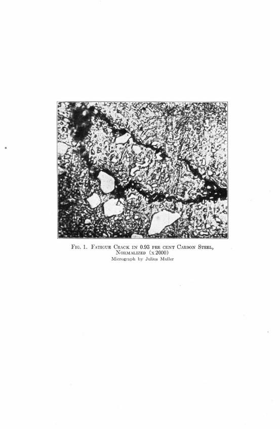
FIG. 1. FATIGUE CRACK IN 0.93 PER CENT CARBON STEEL,NORMALIZED (x2000)
Micrograph by Julius Muller

FIG. 2. FATIGUE CRACK IN SPECIMEN OF AXLE STEEL (X 10)Micrograph by Julius Muller. The specimen had been coated withwhiting for the oil and whiting test described on page 10, andin cleaning off the whiting to permit direct observation of thesurface some whiting was rubbed into the crack; hence it appearswhite.
FIG. 3. LOCATION OF CRACK SHOWN BY OIL-
WHITING TEST
A STUDY OF FATIGUE CRACKS IN CAR AXLES
tigue limits than those indicated in the preceding paragraphs. At theshoulders of car axles and of the specimens tested the stresses presentare higher than those computed by the ordinary formulas of mech-anics of materials. These ordinary formulas take no account of sud-den changes of the cross-section of a piece. Such sudden changes causestresses in excess of the ordinary computed stress, and the smaller theradius of fillet at a change of section the worse is the stress-concentra-tion. This stress-concentration for car axles and for the specimens cutfrom car axles is discussed more fully on p. 13. The excess stressdue to such stress-concentration is probably not less than 45 per centabove the value given by the ordinary formulas. Fatigue test speci-mens are ordinarily so designed as to minimize this localized stress;hence it is to be expected that specimens having stress-concentrationabout the same as that present in car axles will show lower nominalvalues of stress at the fatigue limit than the values given by tests ofspecimens specially designed to minimize stress-concentration.
III. TESTS FOR THE DETECTION OF FATIGUE CRACKS
7. Methods of Detecting Fatigue Cracks.-Fatigue cracks devel-oped under repeated stress could probably be detected long before theyhad spread to failure if it were feasible to search for them with ahigh-power microscope. Figure 1 shows a high-magnification micro-graph of a fatigue crack in normalized spring steel. The use of ahigh-power microscope, however, involves a very careful polishing ofthe surface examined, and the search for cracks over any considerablearea would consume a very long time. The use of a high-power micro-scope would be quite impractical for shop examination of axles.
In the tests recorded in this bulletin a low-power microscope (notmore than 10 times magnification) was found to be a useful instru-ment for finding fatigue cracks. A good shop polish was all that wasrequired on the surface to be examined, and a search for cracks didnot usually require more than a quarter of an hour per specimen.Figure 2 shows the appearance of a fatigue crack detected by thismethod. However, it is somewhat doubtful whether this method wouldbe practical for general shop examination of axles.
Another useful method of locating cracks too fine to be seen bythe unaided eye is that used for stee. plates by Dr. Rawdon of theT. S. Bureau of Standards. He smears a specimen over with a wash

ILLINOIS ENGINEERING EXPERIMENT STATION
of kerosene oil in which is suspended iron "mud" from lapping discs.When the specimen is magnetized the location of cracks is shown bythe gathering of particles of iron "mud" along the cracks.*
A simple method of detecting fatigue cracks is in use by theAmerican Steel Foundries. A casting is subjected to repeated stressin a special testing machine, and where a crack is suspected the sur-face is sprayed with gasoline. The gasoline penetrates any small crack,and as repeated stress is applied a bubbling mixture of gasoline andair is forced out of the crack. The line of bubbles formed locates thecrack. This method is difficult to apply in a shop not equipped withmachinery which can be used to apply repeated stress at a rate of atleast 10 to 20 cycles per second.
A method which is used in some railroad shops, including theshops of the Chicago Rapid Transit Company, and which was usedin this investigation, is as follows: The car wheels are removed froman axle, and the surface of the axle near the fillets, where almost allfatigue cracks occur, is rubbed with oil and then wiped clean. Ifcracks exist the oil works down into them and is not removed whenthe surface is wiped clean. The surface is then painted over with awash of whiting and alcohol. When this coating is dry the axle is ro-tated and struck smartly with a hammer. This hammering squeezesthe oil out of the minute cracks and discolors the whiting, thus locat-ing the cracks. Figure 3 is from a photograph of an oil stain on whit-ing showing the location of a crack.
8. Material and Test Specimens.-A number of axles were usedin this experimental study of fatigue cracks. They were furnished bythe Chicago Rapid Transit Company. The service of each axle is asfollows:
Heat 25 092, axle 1680, placed in service February 4, 1916; hasmade 371 160 miles.
Heat 28 120, a General Electric Co. No. 243 axle, serial number1840, placed in service May 19, 1916; has made 357 329miles.
Heat 49 075, a Westinghouse No. 114 axle, serial number 19;never has been in service.
SAxle 1386, placed in service May 1, 1919; has made 326 925miles.
*Technologic Paper 156, U. S. Bureau of Standards.

A STUDY OF FATIGUE CRACKS IN CAR AXLES
TABLE 1
CHEMICAL ANALYSES OF STEEL IN AXLES
Heat No.
25 092...........
28 120...........
49 075...........
5 723...........
Content, per cent
Carbon Manganese Silicon Phosphorus Sulphur
0.45 0.49 0.150 0.019 0.046
0.47 0.66 0.170 0.015 0.035
0.46 0.40 ..... 0.031 0.032
0.62 0.43 0.150 0.017 0.027
TABLE 2
PHYSICAL PROPERTIES OF STEEL IN AXLES
Heat No.
25 092...........
28 120...........
49 075...........
5 723...........
ProportionalElasticLimit
lb. per sq. in.
57 000*
59 500*
40 800
53 500
Ultimate ElongationTensile in 2 inches
Strengthlb. per sq. in. per cent
92 000 22.0
100 500 22.0
91 700 25.2
105 100 18.2
Reductionof Area Brinell
Numberper cent
50
45
48 148
35 201
*Yield point.
Heat 5723, coach axle Rapid Transit serial number 1012, placedin service August, 1911; has made approximately 800 000miles.
The chemical analyses of these various heats given in Table 1 areanalyses made by Robert W. Hunt and Company with the exceptionof the analysis of heat 5723 which was made at the University ofIllinois. Tensile tests were made on specimens from each heat of steel.The results of these tests are given in Table 2.
The axles from which test specimens were cut were all heattreated. The exact heat treatment is not known, but the specificationsunder which the axles were purchased called for a heat treatment,consisting of an oil quench and a subsequent draw, to be carried outon the axle after forging. The temperature for quenching and draw-
ing and the length of exposure to these temperatures are to be such as
will give the following physical properties as judged by tension testson specimens 1/2 in. in diameter, with a 2-in. gage length:

ILLINOIS ENGINEERING EXPERIMENT STATION
FIG. 4. SPECIMEN FOR STUDY OF FATIGUE CRACKS
FIG. 5. TESTING MACHINE USED IN STUDY OF FATIGUE CRACKS
Yield point, 50 000 lb. per sq. in.Elongation in 2 inches, not less than 22 per cent.Reduction of area, not less than 45 per cent.
The form and size of the specimens used for repeated-stress teststo develop cracks are shown in Fig. 4, and the testing machine used isshown in Fig. 5. The specimen is loaded as a rotating cantilever beamand is subjected to cycles of reversed bending-a loading similar ingeneral character to that on car axles in service. For the specimenshown in Fig. 4 there is a slightly greater degree of stress-concentra-tion at the fillet than exists in ordinary car axles.* Figure 6 showsthe general plan of cutting specimens from an axle. It is to be notedthat the fillets on the specimens are nearly tangent to a fillet on theaxle.
9. Procedure in Tests for Detection of Fatigue Cracks.-The pro-cedure followed in tests to detect fatigue cracks before failure was as
*If D is the larger diameter of a shaft at a shoulder, d the smaller diameter of shaft atthe shoulder, and r the radius of fillet, the generally accepted treatment indicates that the stress-concentration increases as some direct function of D/d and also as some direct function of d/r.For the specimen shown in Fig. 4, D/d = 2 and d/r = 5.3; for car axles average values are:D/d = 1.3 and d/r = 6.8.

A STUDY OF FATIGUE CRACKS IN CAR AXLES
FIG. 6. LOCATION OF TEST SPECIMENS IN AXLE
follows: To start a fatigue crack a load was applied to a specimenso as to set up a stress somewhat above the estimated endurancelimit, and several thousand cycles of stress were applied. The machinewas then stopped and a careful search was made for fatigue cracks,using the whiting and oil method outlined on p. 10, also direct exam-ination through a low-power microscope. If no crack was detectedthe specimen was subjected to another series of cycles of stress withthe same, or a slightly greater, range; if a crack was detected the num-ber of cycles of stress already applied was noted, and the test thencontinued to failure, the total number of cycles required being againnoted. Several different stresses were used for different specimensfrom each axle, and the endurance limit was estimated.*
Table 3 gives the data of the fatigue tests and Table 4 the esti-mated endurance limits. It is to be noted that these endurance limits,determined from tests of specimens of the type shown in Fig. 4, aresomewhat low for steel of the static strength shown by the test resultsgiven in Table 2. In the specimen shown in Fig. 4 there is consider-able stress-concentration at the fillet. In the case of axle 19 from heat49 075, in addition to the tests on specimens similar to that shown inFig. 4, fatigue tests were made on standard rotating-beam specimens0.3 in. in diameter. These standard specimens are shown in Fig. 7,and it is to be observed that the fillets at the reduced section are ofsuch large radius that the stress-concentration is negligible. Thesestandard specimens give an endurance limit 1.46 times that given bythe tests of the larger specimens (Fig. 4). That is, judged by the re-sults of fatigue tests, the effective stress-concentration factor at thefillet of the specimen shown in Fig. 3 may be estimated at 1.46. Using
*The endurance limit can be estimated with a fair degree of accuracy from tabulated datafor a series of specimens tested under different stresses. It can be estimated somewhat more ac-curately by plotting, for these test data, a diagram with values of stress (S) as ordinates andvalues of number of cycles of stress for fracture (N) as abscissas. The value of stress for whichthis S-N diagram becomes horizontal is the endurance limit. See Univ. of Ill. Eng. Exp. Sta.Bul. 124. p. 90.

ILLINOIS ENGINEERING EXPERIMENT ST N
TABLE 3
RESULTS OF FATIGUE TESTS OF SPECIMENS CUT FROM CAR AXLES
Unless specifically stated otherwise specimens are as shown in Fig. 4; L with a specimen numberdenotes a long specimen; S, a short specimen.
Testing machine as shown in Fig. 5, speed 1300 r.p.m.
SpecimenComputedUnit-stress
lb. persq. in.
Number ofCycles ofStress atDetectionof Crack
Number ofCycles ofStress atFracture
EnduranceLimit
lb. persq. in.
Specimens from Axle 1680, Heat 25 092
Remarks
1680AL.. .......
1680BL..........
1680CL.........
1680DL.........
1680AS .........
1680BS .........
28 200
27 00030 200
26 100
28 20023 600
27 20017 500
29 50013 500
427 200
441 300
542 000
327 600. . . . . . . . . .
1 085 000
3 981 000452 800
3 049 500
1 319 800
3 867 000
19 048 300
27 000
Lessthan
17 000
greaterthan
14 000
Specimen unbroken
Specimen unbroken
Crack developedTest of cracked speci-
men
Crack developedTest of cracked speci-
men
Crack developedTest of cracked speci-men; specimen unbro-ken
Specimens from Axle 1840, Heat 28 120
1840AL.........
1840BL .........
1840CL..........
1840DL.........
1840BL ..........
1840CL . . ... .
29 700
28 000
22 00025 000
27 90030 80021 000
29 00018 000
25 00029 00014 000
3 759 000630 000
472 600
3 536 200800 000
. . . . . . . . . .
443 500
13 169 700
28 137 70015 381 000
2 749 100
4 530 700
20 169 900
28 000
less than18 000
greaterthan
14 000
Specimen unbroken
Specimen unbrokenSpecimen unbroken
No crack developedCrack developedTest of cracked speci-
men
Crack developedTest of cracked speci-
men
No crack developedCrack developedSpecimen unbroken
Small "Farmer" Specimens from Axle 19, Heat 49 075
19AF ..........
19BF............
19CF............
19D F ............
19EF............
19FF............
19GF............
43 000
40 000
37 000
35 500
35 000
34 000
45 000
................................ ... . .. .............. ... . .. ...52 100
341 500
766 400
1 974 000
55 608 500
19 325 000
68 909 900
67 000
35 000
Specimen unbroken
Specimen unbroken
~
- ~ -- ~---~~~-;~- ~-'-~^~~
I
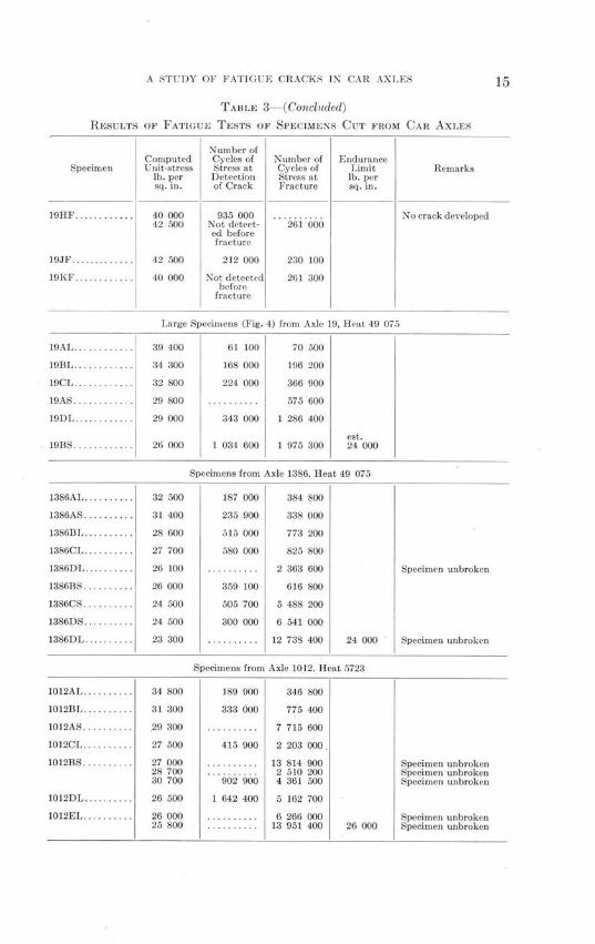
A STUDY OF FATIGUE CRACKS IN CAR AXLES
TABLE 3-(Concluded)
RESULTS OF FATIGUE TESTS OF SPECIMENS CUT FROM CAR AXLES
Specimen
19H F............
19JF .............
19K F ............
19AL ............
19BL ............
19CL ............
19AS............
19D L ............
19BS ...........
ComputedUnit-stress
lb. persq. in.
40 00042 500
42 500
40 000
Number ofCycles ofStress atDetectionof Crack
935 000Not detect-ed beforefracture
212 000
Not detectedbeforefracture
Number ofCycles ofStress atFracture
261 000
230 100
261 300
EnduranceLimitlb. persq. in.
Remarks
No crack developed
Large Specimens (Fig. 4) from Axle 19, Heat 49 075
39 400 61 100 70 500
34 300 168 000 196 200
32 800 224 000 366 900
29 800 .......... 575 600
29 000 343 000 1 286 400
est.26 000 1 034 600 1 975 300 24 000
1386AL .........
1386AS .........
1386BL.........
1386CL....... .
1386DL .........
1386BS .........
1386CS..........
1386DS..........
1386DL .........
1012AL..........
1012BL.........
1012AS..........
1012CL..........
1012BS ..........
1012DL..........
1012EL ..........
32 500
31 400
28 600
27 700
26 100
26 000
24 500
24 500
23 300
34 800
31 300
.29 300
27 500
27 00028 70030 700
26 500
26 00025 800
Specimens from Axle 1386, Heat 49 075
187 000 384 800
235 900 338 000
515 000 773 200
580 000 825 800
.......... 2 363 600
359 100 616 800
505 700 5 488 200
300 000 6 541 000
.......... 12 738 400 24 000
Specimens from Axle 1012. Heat 5723
189 900 346 800
333 000 775 400
.......... 7 715 600
415 900 2 203 000.
... . 13 814 900... . 2 510 200
902 900 4 361 500
1 642 400 5 162 700
...... .. 6 266 000......... 13 951 400 26 000
Specimen unbroken
Specimen unbroken
Specimen unbrokenSpecimen unbrokenSpecimen unbroken
Specimen unbrokenSpecimen unbroken

ILLINOIS ENGINEERING EXPERIMENT STATION
TABLE 4
FATIGUE STRENGTH OF SPECIMENS CUT FROM AXLES
Fatigue specimens taken from steel near the outside of axle (see Fig. 6)
Estimated Endurance Limitlb. per sq. in.
Axle Heat No. Standard Rotating-"Farmer" cantileverSpecimen Specimen
(Fig. 7) (Fig. 4)
1680.......... 25 092 ...... 27 000
1840.......... 28 120 ...... 28 000
19............ 49 075 35 000 24 000*
1386........... 49 075 ...... 24 000
1012.......... 5 723 ...... 26 000
*Based partly on results for axle 1386 from same heat.
0a40"dla. OV9ad/s '
/30"mW1 0//a.7
FIG. 7. STANDARD ROTATING-BEAM FATIGUE SPECIMEN
the results of Timoshenko and Dietz* the theoretical stress-concentra-tion at the fillets is about 1.95.
10. Results of Tests for Detection of Fatigue Cracks.-Table 5gives the results of the tests to determine how early in the "life" of aspecimen a fatigue crack can be detected by the oil and whitingmethod. In connection with the last column of Table 5 it may benoted that a car axle is subjected to about 600 cycles of reversed flex-ure per mile of travel, and that most of the cycles involve unit-stresses(computed from the nominal axle load) of not more than about 6500lb. per sq. in.
Figure 8 shows graphically the results presented in Table 5. Itis seen that under stresses more than 30 per cent above the endurancelimit of an axle, failure may be expected in less than 100 000 cyclesof such stress after a crack can be detected.
*Trans. A. S. M. E. 1925, p. 210.

A STUDY OF FATIGUE CRACKS IN CAR AXLES 17
TABLE 5
DETECTION OF FATIGUE CRACKS IN SPECIMENS CUT FROM AXLES
Rotating-cantilever specimens. Fig. 4.
Axle
1680............................
19 .............................
1386............................
1012............................
Heat No.
25 092
49 075
49 075
5 723
Stress inSpecimenexpressed
as Percent-age of
EnduranceLimit
105
164143136121108
135130119115108102102
134120106102
Percentageof Total
"Life" atDetectionof Crack
39
8776612752
494967705895
55431931
Cycles ofStress
betweenDetectionof Crack
and Fracture
658 000
9 40046 000
143 000943 000940 000
198 000102 100258 000244 000257 700
4 982 5006 241 000
157 000442 000
1 787 0003 521 000
Car axles are much larger than the largest specimen tested in theinvestigation, and it is of interest to consider the effect of size ofspecimen on the ease with which a crack can be detected. A series oftests has been made on small specimens (diameter 0.3 inch) like thatshown in Fig. 7, cut from uninjured parts of axles previously tested.Oil and whiting tests were made to detect cracks, and the results in-dicated that, in the small specimens, the cycles of stress occurringbetween the detection of a crack and failure are much fewer for agiven stress than is the case for the larger specimens (diameter 1.0inch). This result seems reasonable. Roughly speaking, the minimumsize of a crack which can be detected is independent of the size of speci-men; the proportionate amount of damage done by this size of crackwould, however, be greater for a small specimen than for a large one.Car axles are much larger than the largest specimen tested, and itwould seem reasonable to conclude tentatively that fatigue cracks canbe detected earlier in the life of a car axle than in the life of the larg-est specimen tested in the course of this investigation.
An interesting phenomenon noted in connection with fatigue testsof specimens cut from axles was that in all cases but one the fatigue

ILLINOIS ENGINEERING EXPERIMENT STATION
Cyc/es of Stress from? Dz2eec1/o/1 of Cl'ac to Fa//re
FIG. 8. LENGTH OF ENDURANCE OF SPECIMENS (FIG. 4) AFTER
DETECTION OF FATIGUE CRACK
failure started on that side of the specimen nearest the axis of theaxle. That is, as shown in Fig. 6, failure started at b rather than at a.This seems to indicate that in service, the material near the surfaceof an uncracked axle has not been appreciably injured by the cycles ofrepeated stress to which it has been subjected-at least the injury hasnot been sufficient to compensate for the tendency towards the oc-currence of weaker steel at the axis of the axle, where the effect of therolling is less than at the surface.
IV. SPREAD OF FATIGUE CRACKS UNDER WORKING STRESSES
11. High Stresses and Low Stresses in Car Axles.-It is evidentfrom the foregoing discussion that if the service of a car axle involveda continuous succession of cycles of stress well above the endurancelimit, no effective system of inspection for cracks would be feasible;the intervals between successive inspections would have to be soshort as to render inspection prohibitively expensive. However, as.already noted, the ordinary cycle of stress in a car axle does not in-volve a stress much greater than 6500 lb. per sq. in. (computed unit-stress)-about one-quarter of the endurance limit.
A question which, then, becomes of prime importance is: Docracks produced by occasional high stress continue to spread under

A STUDY OF FATIGUE CRACKS IN CAR AXLES
TABLE 6
SPREAD UNDER SUBSEQUENT LOW STRESS OF CRACKS STARTED UNDER HIGH STRESS
In each specimen a crack approximately 0.1 inch long was developed under cycles of stress abovethe endurance limit of the virgin metal.
Axle
1680 .............
1840.............
Heat No.
25 092
28 120
Limiting Unit-stress for Spread of Crack
Greater than
Percentage ofEndurance
lb. per sq. in. Limit of VirginMetal
14 000 52
14 000 50
Less than
Percentage ofEndurance
lb. per sq. in. Limit of VirginMetal
17 000 63
18 000 64
subsequent cycles of lower stress, or, in other words, do such cracksreduce the fatigue strength of the axle, and if so, by how much?
12. Tests of Spread of Cracks in Axle Steel.-The experimentalstudy of this question was carried on as follows: Using cycles of stressa few thousand pounds per square inch above the endurance limitcracks of a fairly definite length (about 0.10 in.) were produced inthree specimens taken from each of two axles-six specimens in all.These specimens were then subjected to cycles of stress of differentmagnitude, the spread of crack was studied, and the endurance limitwas estimated between rather wide limits. Of course, for stresses be-low the endurance limit of the cracked specimen the crack did not in-crease in size under further cycles of stress. The endurance limit ofsuch specimens was then compared with the endurance limit of similarspecimens in which no cracks had been started. The test data of thefatigue tests are given in Table 3 and the results of these tests ofcracked specimens in Table 6. It will be noted that for both casesthe reduction in endurance limit was found to be more than 35 percent and less than 50 per cent.
Figure 9 shows the growth of cracks with increasing number ofcycles of stress. The outstanding characteristic of these curves is theirindication of an increasing rate of spread of cracks as the number ofcycles of stress increases.
13. Results of Tests for Spread of Cracks.-The normal workingstresses on car axles are about one-quarter of the endurance limit, and

ILLINOIS ENGINEERING EXPERIMENT STATION
- '/fi Stress,-t24000 /b2pet-
I I I I I I I IAAx/e /680 - /7/'e 250_s _
-- 7a'^,,-a",7Toe / /i/7 of -- Vi'w/~'l sfee/, 27000/b.
,oer5\s~y //?.izzl'~I /.i _
- - ~ ~ d 51,e~s-s /4a4060 /Lspe-s//i
i0
a4
Oa21
C// 2// s 3 ess/////io7S of Cyc/es of Sfress
FIG. 9. GROWTH OF FATIGUE CRACKS
it would appear probable that there is little danger that cracks startedby occasional abnormal stresses will spread under subsequent workingstresses. It would appear highly probable that, when formed at all,fatigue cracks are formed under occasional high stress-such stress asis caused by flat wheels, bad joints, tight frogs, etc.-and that cracksonce formed spread only under the action of occasional stresses abouttwice as high as ordinary working stresses. It is evident that in thisconnection an experimental study of the frequency and magnitude ofabnormal stresses in car wheels (stresses above ordinary workingstresses) would be of great importance. Such a study has been begunin connection with this investigation.
'X/e /qa - tear z-f \ 'ir Streso 2/000 /d pe,' s. /z--- 1'i7rz'c L/ i/ o lg/ --- -
stee/, 28000 /6 per s. /52
fL// St/ress,/800 /b.per s ~/,7.
S-/1 6// S/ress /400 /4.--- perC si1 . C/ra-c' did a70/ sp'reada
~'""'^"' ' "

A STUDY OF FATIGUE CRACKS IN CAR AXLES
In view of the results of tests of laboratory specimens and inview of the evidence that the smallest detectable crack in an axle doesnot indicate so near an approach to failure as does the smallest de-tectable crack in a laboratory specimen, it would appear to be a reas-onable tentative conclusion that a careful periodic inspection of caraxles for cracks is a fairly reliable safeguard against fatigue failureof axles in service. This conclusion is in accord with the experienceof both English and American engineers, who report that periodic in-spection for cracks of electric car axles and of locomotive axles resultsin the detection of nearly all fatigue cracks before they spread tofailure. In the case of electric railway car axles, judging by the ex-perience of the Chicago Rapid Transit Company, inspections for every100 000 miles of travel seem effective.*
V. CONCLUSIONS
14. Summary of Tests and Conclusions.-The tests reported inthis bulletin, which is a report of progress, are believed to give somesignificant information concerning the appearance and spread of fa-tigue cracks caused by repeated stress in car axles. The tests do notcover sufficient ground to give any precise quantitative values for lim-iting stresses or rates of spread of cracks.
With the use of a rotating-beam type of testing machine, fatiguecracks were produced in specimens cut from car axles. The critical di-ameter of these specimens was about 1 inch, and under various condi-tions of stress a study was made of the progress of fatigue cracksfrom their first appearance to the complete fracture of a specimen.
Fatigue cracks were detected by the use of a low-power micro-scope, and also by the discoloration of a coating of whiting on thespecimen by oil squeezed out of a crack when the specimen was sub-jected to bending stress. The oil and whiting method is one used inshop practice.
The following summary of conclusions is given:(1) By means of simple methods, such as are used in some
railroad shops, fatigue cracks in test specimens cut from car axlesand subjected to repeated stress were detected before final fail-ure of the specimen occurred.
*See The Engineer (London) Jan. 5, 1923, p. 1, staff article on the failure of locomotivecranks and axles.

ILLINOIS ENGINEERING EXPERIMENT STATION
(2) Specimens in which a fatigue crack was produced bycycles of stress 20 per cent above the fatigue limit resisted beforefinal fracture from 250 000 to 1 000 000 cycles of stress after thecrack had been detected.
(3) The higher the stress the fewer were the cycles of stressoccurring between the detection of a fatigue crack and the failureof the specimen, and the larger the percentage of the elapsed"life" of the specimen at the appearance of the crack.
(4) For test specimens having a diameter of 0.3 inch for agiven stress fewer cycles of stress occurred between detection ofa crack and final failure than was the case for specimens havinga diameter of 1 inch. It seems reasonable to conclude that for caraxles having a diameter of 4 to 6 inches the number of cycles ofstress between the appearance of a detectable crack and failurewould be materially larger than was the case for the 1-inch speci-mens.
(5) Test specimens in which a fatigue crack had been startedand had spread to a definite length showed a continuing spread of
such a crack to failure under subsequent cycles of stress having amagnitude of 64 per cent of the endurance limit of the virgin
steel; but such a crack in a test specimen did not spread further
under cycles of stress having a magnitude of 50 per cent of the
endurance limit of the virgin steel.(6) The results of these tests, taken in conjunction with ser-
vice records, seem to indicate that periodical shop inspection by
means of the oil-whiting test described on page 10 may be ex-
pected to have a good degree of effectiveness in detecting incipient
fatigue cracks in car axles in service, before failure of the axle is
imminent.

RECENT PUBLICATIONS OFTHE ENGINEERING EXPERIMENT STATION*
Bulletin No. 130. The Reheating of Compressed Air, by C. R. Richards andJ. N. Vedder. 1922. Fifty cents.
Bulletin No. 131. A Study of Air-Steam Mixtures, by L. A. Wilson withC. R. Richards. 1922. Seventy-five cents.
Bulletin No. 132. A Study of Coal Mine Haulage in Illinois, by H. H. Stoek,J. R. Fleming, and A. J. Hoskin. 1922. Seventy cents.
Bulletin No. 133. A Study of Explosions of Gaseous Mixtures, by A. P.Kratz and C. Z. Rosecrans. 1922. Fifty-five cents.
Bulletin No. 134. An Investigation of the Properties of Chilled Iron CarWheels. Part II. Wheel Fit, Static Load, and Flange Pressure Strains. UltimateStrength of Flange, by J. M. Snodgrass and F. H. Guldner. 1922. Forty cents.
Circular No. 10. The Grading of Earth Roads, by Wilbur M. Wilson. 1923.Fifteen cents.
Bulletin No. 135. An Investigation of the Properties of Chilled Iron CarWheels. Part III. Strains Due to Brake Application. Coefficient of Friction andBrake-Shoe Wear, by J. M. Snodgrass and F. H. Guldner. 1923. Fifty cents.
Bulletin No. 136. An Investigation of the Fatigue of Metals. Series of1922, by H. F. Moore and T. M. Jasper. 1923. Fifty cents.
Bulletin No. 137. The Strength of Concrete; its Relation to the CementAggregates, and Water, by A. N. Talbot and F. E. Richart. 1923. Sixty cents.
Bulletin No. 138. Alkali-Vapor Detector Tubes, by Hugh A. Brown andChas. T. Knipp. 1923. Twenty cents.
Bulletin No. 139. An Investigation of the Maximum Temperature and Pres-sures Attainable in the Combustion of Gaseous and Liquid Fuels, by G. A. Good-enough and G. T. Felbeck. 1923. Eighty cents.
Bulletin No. 140. Viscosities and Surface Tensions of the Soda-Lime-SilicaGlasses at High Temperatures, by E. W. Washburn, G. R. Shelton, and E. E.Libman. 1924. Forty-five cents.
Bulletin No. 141. Investigation of Warm-Air Furnaces and Heating Sys-tems, Part II, by A. C. Willard, A. P. Kratz, and V. S. Day. 1924. Eighty-fivecents.
Bulletin No. 142. Investigation of the Fatigue of Metals; Series of 1923, byH. F. Moore and T. M. Jasper. 1924. Forty-five cents.
Circular No. 11. The Oiling of Earth Roads, by Wilbur M. Wilson. 1924.Fifteen cents.
Bulletin No. 143. Tests on the Hydraulics and Pneumatics of House Plumb-ing, by H. E. Babbitt. 1924. Forty cents.
Bulletin No. 144. Power Studies in Illinois Coal Mining, by A. J. Hoskinand Thomas Fraser. 1924. Forty-five cents.
Circular No. 12. The Analysis of Fuel Gas, by S. W. Parr and F. E. Vanda-veer. 1925. Twenty cents.
*Only a partial list of the publications of the Engineering Experiment Station is publishedin this bulletin. For a complete list of the publications as far as Bulletin No. 134, see that bulletinor the publications previous to it. Copies of the complete list of publications can be obtained withoutcharge by addressing the Engineering Experiment Station, Urbana, Ill.

ILLINOIS ENGINEERING EXPERIMENT STATION
Bulletin No. 145. Non-Carrier Radio Telephone Transmission, by H. A.Brown and C. A. Keener. 1925. Fifteen cents.
Bulletin No. 146. Total and Partial Vapor Pressures of Aqueous AmmoniaSolutions, by T. A. Wilson. 1925. Twenty-five cents.
Bulletin No. 147. Investigation of Antennae by Means of Models, by J. T.Tykociner. 1925. Thirty-five cents.
Bulletin No. 148. Radio Telephone Modulation, by H. A. Brown and C. A.Keener. 1925. Thirty cents.
Bulletin No. 149. An Investigation of the Efficiency and Durability of SpurGears, by C. W. Ham and J. W. Huckert. 1925. Fifty cents.
Bulletin No. 150. A Thermodynamic Analysis of Gas Engine Tests, by C. Z.Rosecrans and G. T. Felbeck. 1925. Fifty cents.
Bulletin No. 151. A Study of Skip Hoisting at Illinois Coal Mines, by ArthurJ. Hoskin. 1925. Thirty-five cents.
Bulletin No. 152. Investigation of the Fatigue of Metals; Series of 1925, byH. F. Moore and T. M. Jasper. 1925. Fifty cents.
*Bulletin No. 153. The Effect of Temperature on the Registration of SinglePhase Induction Watthour Meters, by A. R. Knight and M. A. Faucett. 1926.Fifteen cents.
*Bulletin No. 154. An Investigation of the Translucency of Porcelains, byC. W. Parmelee and P. W. Ketchum. 1926. Fifteen cents.
Bulletin No. 155. The Cause and Prevention of Embrittlement of BoilerPlate, by S. W. Parr and F. G. Straub. 1926. Thirty-five cents.
Bulletin No. 156. Tests of the Fatigue Strength of Cast Steel, by H. F. Moore,1926. Ten cents.
*Bulletin No. 157. An Investigation of the Mechanism of Explosive Reactions,by C. Z. Rosecrans. 1926. Thirty-five cents.
*Circular No. 13. The Density of Carbon Dioxide with a Table of RecalculatedValues by S. W. Parr and W. R. King, Jr. 1926. Fifteen cents.
*Circular No. 14. The Measurement of the Permeability of Ceramic Bodies,by P. W. Ketchum, A. E. R. Westman, and R. K. Hursh. 1926. Fifteen cents.
*Bulletin No. 158. The Measurement of Air Quantities and Energy Losses inMine Entries, by A. C. Callen and C. M. Smith. 1926. Forty-five cents.
*Bulletin No. 159. An Investigation of Twist Drills. Part II., by B. W. Bene-dict and A. E. Hershey. 1926. Forty cents.
*Bulletin No. 160. A Thermodynamic Analysis of Internal Combustion EngineCycles, by G. A. Goodenough and J. B. Baker. 1927.
*Bulletin No. 161. Short Wave Transmitters and Methods of Tuning, byJ. T. Tykociner. 1927. Thirty-five cents.
*Bulletin No. 162. Tests on the Bearing Value of Large Rollers, by W. M.Wilson. 1927. Forty cents.
*Bulletin No. 163. A Study of Hard Finish Gypsum Plasters, by Thomas N.McVay. 1927. Twenty-five cents.
*Bulletin No. 164. Tests of the Fatigue Strength of Cast Iron, by H. F. Moore,S. W. Lyon, and N. P. Inglis. 1927. Thirty cents.
*Bulletin No. 165. A Study of Fatigue Cracks in Car Axles, by H. F. Moore.1927. Fifteen cents.
*A limited number of copies of bulletins starred are available for free distribution.

THE UNIVERSITY OF ILLINOISTHE STATE UNIVERSITY
UrbanaDAVID KINLEY, Ph.D., LL.D., President
THE UNIVERSITY INCLUDES THE FOLLOWING DEPARTMENTS:
The Graduate SchoolThe College of Liberal Arts and Sciences (Curricula: General with majors, in
the Humanities and the Sciences; Chemistry and Chemical Engineering;Pre-legal, Pre-medical and Pre-dental; Journalism, Home Economics, Eco-nomic Entomology and Applied Optics)
The College of Commerce and Business Administration (Curricula: GeneralBusiness, Banking and Finance, Insurance, Accountancy, Railway Adminis-tration, Railway Transportation, Industrial Administration, Foreign Com-merce, Commercial Teachers, Trade and Civic Secretarial Service, PublicUtilities, Commerce and Law)
The College of Engineering (Curricula: Architecture, Ceramics; Architectural,Ceramic, Civil, Electrical, Gas, General, Mechanical, Mining, Municipal andSanitary, and Railway Engineering; Engineering Physics)
The College of Agriculture (Curricula: General Agriculture; Floriculture; HomeEconomics; Landscape Architecture; Smith-Hughes-in conjunction with theCollege of Education)
The College of Education (Curricula: Two year, prescribing junior standing foradmission-General Education, Smith-Hughes Agriculture, Smith-HughesHome Economics, Public School Music; Four year, admitting from the highschool-Industrial Education, Athletic Coaching, Physical Education
The University High School is the practice school of the College ofEducation)
The School of Music (four-year curriculum)The College of Law (Three-year and four-year curricula based on two years of
college work)The Library School (two-year curriculum for college graduates)The College of Medicine (in Chicago)The College of Dentistry (in Chicago)The School of Pharmacy (in Chicago)The Summer Session (eight weeks)Experiment Stations and Scientific Bureaus: U. S. Agricultural Experiment
Station; Engineering Experiment Station; State Natural History Survey;State Water Survey; State Geological Survey; Bureau of EducationalResearch.
The Library collections contain (June 1, 1926) 711,753 volumes and 155,331pamphlets.
For catalogs and information address
THE REGISTRARUrbana, Illinois

c
1
·ii


![LIFE ASSESSMENT OF POWER PLANT BOILER …Figure 2. shows cracks resulted by corrosion-fatigue. Figure 2. A family of longitdinal cracks resulting from fluctuation in internal pressure[2]](https://static.documents.pub/doc/80x56/5e3c9af517fb8a5f226bd0c0/life-assessment-of-power-plant-boiler-figure-2-shows-cracks-resulted-by-corrosion-fatigue.jpg)