Progress In Electromagnetics Research, Vol. 131, 19–44, 2012 A STUDY OF THE EMC PERFORMANCE OF A GRADED-IMPEDANCE, MICROWAVE, RICE-HUSK AB- SORBER M. N. Iqbal 1, * , F. Malek 2 , S. H. Ronald 2 , M. Shafiq 2 , K. M. Juni 3 , and R. Chat 3 1 School of Computer and Communication Engineering, Universiti Malaysia Perlis (UniMAP), Taman Seberang Jaya Fasa 3, Kuala Perlis, Perlis 02000, Malaysia 2 School of Electrical System Engineering, Universiti Malaysia Perlis (UniMAP), Taman Seberang Jaya Fasa 3, Kuala Perlis, Perlis 02000, Malaysia 3 Electrical Engineering Department, Politeknik Tuanku Syed Sirajud- din, Pauh Putra, Perlis 02600, Malaysia Abstract—Biomass used for energy, whether it is extracted from forest residues or agricultural waste, contributes in many areas, such as power production, the construction industry, and also as a major source of different organic and inorganic compounds in the petrochemical industry. In recent years, research has identified a very remarkable use of agricultural waste, especially rice husks, as a microwave absorber in a pyramidal shape. However, absorbers built in this shape are fragile and require a very high degree of care, especially near the access panels, doors, and high traffic areas of the anechoic facility. This paper presents the results of a detailed experimental investigation of a more-robust, new design that is based on the concept of impedance or dielectric grading of rice-husk material. The absorber was fabricated using multiple layers of rice-husk material with increasing dielectric loss along the incident wave propagation axis. This type of fabrication technique provides more robust design of the microwave, rice-husk absorber with less thickness, as compared to the geometrically- tapered, pyramid, or wedge absorbers. Free-space transmission and radar cross section (RCS) methods have been used, to study the electromagnetic compatibility (EMC) performance over the frequency range of 4–8 GHz. After the receiving equipment was calibrated by Received 20 July 2012, Accepted 23 August 2012, Scheduled 3 September 2012 * Corresponding author: Muhammad Nadeem Iqbal ([email protected]).
Transcript
Progress In Electromagnetics Research, Vol. 131, 19–44, 2012
A STUDY OF THE EMC PERFORMANCE OF AGRADED-IMPEDANCE, MICROWAVE, RICE-HUSK AB-SORBER
M. N. Iqbal1, *, F. Malek2, S. H. Ronald2, M. Shafiq2,K. M. Juni3, and R. Chat3
1School of Computer and Communication Engineering, UniversitiMalaysia Perlis (UniMAP), Taman Seberang Jaya Fasa 3, Kuala Perlis,Perlis 02000, Malaysia2School of Electrical System Engineering, Universiti Malaysia Perlis(UniMAP), Taman Seberang Jaya Fasa 3, Kuala Perlis, Perlis 02000,Malaysia3Electrical Engineering Department, Politeknik Tuanku Syed Sirajud-din, Pauh Putra, Perlis 02600, Malaysia
Abstract—Biomass used for energy, whether it is extracted fromforest residues or agricultural waste, contributes in many areas, such aspower production, the construction industry, and also as a major sourceof different organic and inorganic compounds in the petrochemicalindustry. In recent years, research has identified a very remarkable useof agricultural waste, especially rice husks, as a microwave absorber ina pyramidal shape. However, absorbers built in this shape are fragileand require a very high degree of care, especially near the accesspanels, doors, and high traffic areas of the anechoic facility. Thispaper presents the results of a detailed experimental investigation of amore-robust, new design that is based on the concept of impedance ordielectric grading of rice-husk material. The absorber was fabricatedusing multiple layers of rice-husk material with increasing dielectricloss along the incident wave propagation axis. This type of fabricationtechnique provides more robust design of the microwave, rice-huskabsorber with less thickness, as compared to the geometrically-tapered, pyramid, or wedge absorbers. Free-space transmission andradar cross section (RCS) methods have been used, to study theelectromagnetic compatibility (EMC) performance over the frequencyrange of 4–8 GHz. After the receiving equipment was calibrated by
Received 20 July 2012, Accepted 23 August 2012, Scheduled 3 September 2012* Corresponding author: Muhammad Nadeem Iqbal ([email protected]).
20 Iqbal et al.
the thru-reflect-line (TRL) calibration technique, the experiments wereperformed inside the anechoic chamber. The performance of theabsorber was evaluated by incorporating the effects of circular-holeperforation, cross-polarized seams, and different metallic back plates.The proposed absorber demonstrated good performance (< −10 dB)for normal and 60◦ off the normal incident angles over the frequencyrange of 4–8 GHz. Reflectivity performance also was found to becomparable to one of the commercially-available absorbers.
1. INTRODUCTION
Rice is the most popular food item throughout the world, andproducing the crop contributes a major agricultural waste in theform of rice husks. Rice-husk ash (RHA), another by-product ofthe rice crop that is obtained after burning rice husks in ferro-cement furnaces, has been used as a replacement material for thecement in such furnaces [1]. Rice husks are used in many ways,including cattle feed, fuel for furnaces and gasifiers, and feedstockfor chemical, paperboard, and silica industries [2]. However, itseffectiveness in electromagnetic energy absorption has been proven inrecent years [3]. Rice husks contain high contents of Carbon (35–37%) which is considered as a lossy non-metallic conductor. Highsurface area and lossy nature of the Carbon help to attenuate themicrowaves that pass through the rice husks. Microwave absorbers areused to dampen the cavity resonances, but their most extensive use isin the design of reflectionless environments, such as EMC and antennameasurement anechoic chambers.
In recent years, several semi-anechoic chambers (SACs) and fully-anechoic chambers (FACs) have been designed and fabricated bydifferent manufacturers to simulate the free space environment. Withthe growth of modern electronics and telecommunication productsin medical, commercial, and military command and control systems,demand for electromagnetic compatibility (EMC) chambers withdiversity in size and shape has increased significantly. Electronicproducts must meet both emission and immunity requirements ofEMC regulations before they can be advertised in the market [4].Different regulatory authorities and commissions regulate the EMCissues worldwide. In the United States, the Federal CommunicationsCommission (FCC), and, in Europe, the European Union (EU)regulates the EMC requirements [5].
EMC radiated testing involves radiated emission (RE) testingand radiated susceptibility (RS) testing of the equipment undertest (EUT). Each type of testing requires different anechoic chambers,
Progress In Electromagnetics Research, Vol. 131, 2012 21
i.e., RE testing requires an EMC chamber the performance of which iscomparable to the open area test site (OATS), whereas uniformity ofthe electric field is the main issue for RS testing. The power levels of theradiated signals in these tests, especially in case of RS testing, mightbe dangerous. Therefore, reflectivity-controlled environments, such asreverberation chambers, anechoic chambers, or OATS are necessary toensure the safety of the personnel and the precision of the results.
The electromagnetic performance of any EMC anechoic chamberdepends on the effectiveness of the enclosure’s shielding and thereflectivity of the internally-lined absorbers. The highly conductivenature of the shielded enclosure makes it a multi-frequency resonator,and the total field at any position within the anechoic chamber willbe the vector sum of the incident and reflected waves. Resonantfrequencies depend on the dimensions of the enclosure. The existence ofcomplex, standing-wave patterns can introduce higher-order variabilityin the field strength at the EUT location [6]. The unwanted resonantenvironment can be eliminated by the proper selection of absorbingmaterial in the resonant range. At low frequencies, ferrite tiles canbe a good option because they provide maximum useable volume,but they are expensive and heavy. Pyramid dielectric absorbers areused at microwave frequencies, and their performance is achieved byabsorption through gradual impedance tapering. Tapered impedanceensures the minimum reflection of microwave energy and results in thebest performance of absorbers for EMC applications.
Microwave absorption characteristics of the absorber for high-power applications may vary due to the temperature variations thatoccur due to the heat that is generated [7]. The heat absorbed by themicrowave absorbers within the anechoic shielded chambers is usuallyremoved by natural or forced-convection heat transfer. This heatremoval depends on the air-absorber contact area and the temperaturegradients within the microwave absorber during the heat-transferprocess. However, due to the pyramidal geometry of the microwaveabsorber and the energy distribution of the incident wave, hot spotscan occur on its leading tapered edge where less bulk material ispresent [8]. This will result in impedance mismatches and degradationof the performance of the absorber.
The main concern is the installation of the absorbers insideenclosures, which requires special attention and expertise to minimizethe probability of seams. During the installation of the absorbers, it isalways possible for a seam or slot to occur between adjacent absorberblocks. Such seams and their orientation with respect to the incidentfield are very important because they can affect the whole anechoicenvironment. Incident high-frequency waves can pass through that
22 Iqbal et al.
seam depending upon their wavelength and orientation, and they willbounce back after striking the wall of the metallic enclosure. Thesereflected waves will increase the possibility of false signals at thereceiving port during EMC testing.
The rice-husk absorber has been investigated by many researchers,but their main focus has been to prove its potential use as a microwaveabsorber in the pyramidal shape [3]. Currently, it is important toexplore its practical applications in actual situations, such as inanechoic chambers. In this experiment, very-simple, planar absorbergeometry was used due to ease of its fabrication and robustness ofthe design as compared to the pyramidal design. The concept ofgrading dielectric materials was used in this study to investigatethe performance of the rice husk. Broadband and better reflectivity(< −10 dB) performance has been achieved by using the proposedimpedance grading technique. It is not an easy task to install anabsorber in the corners of an enclosure, so most manufacturers designspecial, miter-joint absorbers for corners. So, it is very important toknow the performance of the graded rice-husk material before usingany piece of the absorber within the enclosure. In this research, weinvestigated the absorber by using simple measurement techniques forits future EMC applications inside anechoic chambers. Some relevanttheoretical aspects concerning the interface reflections according to thetransmission line theory are briefly summarized in Section 2. Then,a detailed description of the EMC characterization of the absorbersis given in Section 3. Section 4 describes the geometrical details ofthe designed absorbers and comprehensive results are presented inSection 5. A comparison, of the performance of the designed absorbers,with a commercially available absorber is also given in Section 6. Someconclusions are summarized and discussed at the end of the paper.
2. INTERFACE REFLECTIONS
Reflection loss at the interface of any two media is related tothe impedance mismatch at the interface [9, 10]. Matching ofboth permittivity and permeability of the interface media results inminimum reflection and ensures the maximum absorption of the energyof the incident waves within the lossy medium. The refractive indexof the target medium is an important parameter to slow down theincident microwaves within the medium. The refractive index of a ricehusk-based absorber is greater than that of air, so microwave signalswill be deflected when they enter the absorber [10]. The shape ofthe dielectric absorbers also plays an important role in minimizing theimpedance mismatch by providing smooth impedance tapering of the
Progress In Electromagnetics Research, Vol. 131, 2012 23
target material, which occurs in a microwave-pyramid absorber.Circuit theory can only be applied to systems that are physically
smaller than the wavelength having lumped elements. Since dielectricabsorbers act as distributed networks, transmission-line theory canbe used at microwave frequencies to explain the scattering of theelectromagnetic waves. The technique of “scattering” parameters,commonly called S-parameters, relates the reflection and transmissioncoefficients of the device to the characteristic impedance of thematerial [5].
2.1. Single Section Transformer and Absorber Analogy
Transmission line theory can be used at high frequencies to explainthe analogy of the single-section, quarter-wave-impedance transformerwith the quarter-wave-dielectric absorber. Partial reflection and
transmission coefficients for both cases are shown in Figure 1.An infinite number of bouncing waves will exist at interfaces 1 and
2, leading to the total reflection as a sum of all partial reflection andtransmission coefficients [10]:
Γ = Γ1 + T12T21Γ3e−2jθ + T12T21Γ2
3Γ2 + . . . (1)
= Γ1 + T12T21Γ3e−2jθ
∞∑
n=0
Γn2Γn
3e−2jθ. (2)
where θ = βl, and β = 2π/λ. Using the geometric series:∞∑
n=0
xn =1
1− x, for |x| < 1 (3)
Γ = Γ1 +T12T21Γ3e
−2jθ
1− Γ2Γ3e−2jθ(4)
Inserting partial transmission coefficients from Figure 1, we can expressthe total reflection coefficient as:
Γ =Γ1 + Γ3e
−2jθ
1 + Γ1Γ3e−2jθ(5)
If the impedance discontinuities at interfaces 1 and 2 are very small,then |Γ1Γ3| << 1, and Equation (5) can be approximated as:
Γ = Γ1 + Γ3e−2jθ (6)
The total reflection is dominated by the reflection at interface 1and interface 2, and the term e−2jθ accounts for the phase delay.This is analogous to the interaction of the microwave signal with thesingle-layer, dielectric material that has a characteristic impedance,ηd = η0/
√εr, and a dielectric constant, εr.
2.2. Multi-section Transformer and Graded Multilayers
Step changes in the characteristic impedance between the sectionsbecome smaller as the number of discrete sections of the transformerincreases. Single-section, quarter-wave impedance transformers andabsorbers both provide the minimum reflection response at thedesign frequency, which results in a narrowband impedance matching.Broadband characteristics of the transformer can be approachedby adding an infinite number of discrete sections. Similarly, anarrowband resonant absorber can be converted into a broadbandabsorber by adding multilayers or by tapering the shape [10, 11].Ideally, infinite layers are required to achieve impedance continuity
Progress In Electromagnetics Research, Vol. 131, 2012 25
Figure 2. Concept of impedance grading with multilayers ofincreasing loss along signal propagation (x-axis).
between the successive layers, but, practically, the discontinuity of theimpedance only can be minimized to a limited extent. Multilayers withdifferent grades of dielectric properties provide very efficient broadbandcharacteristics if the impedance of each successive layer is kept smooth.Smooth impedance grading will enhance the transmission of theincident wave through each successive layer with smaller reflectionsat the interface of each layer. However, these small reflections cannotbe removed completely due to the step impedance between each layer.Transmitted waves will be reflected an infinite number of times withinthe multi-layer absorber and lose their energy before reaching thereflecting enclosure wall. The microwave signals lose their energy dueto the lossy nature of the absorber, and conversion of electrical energyinto heat occurs within the absorber. Figure 2 shows the concept ofimpedance grading with multilayers of increasing loss.
When the structures are properly designed, the wave that emergesfrom a geometrically-graded or a material-graded absorber will have avery small amount of energy and cause minimal disturbances to theanechoic environment. If the geometrical or dielectric gradients areso smooth that we can ignore the impedance variations of consecutivelayers of the microwave absorber, the theory of small reflections fora multi-section transformer can be used, and total input reflectioncoefficient can be expressed by Equation (7):
Γin(ω) =N∑
n=0
Γne−j2nβl (7)
2.3. Heat Transfer in the Absorber
Microwave interaction with the absorber results in energy dissipationand temperature gradients within the absorber. Heat generationdepends on the concentration patterns of electromagnetic energy
26 Iqbal et al.
at different points. Impurities and non-homogenous mixing of theconstituents contribute to the non-uniform concentration of heatwithin the absorber. However, heat transfer through the thermalconduction process within the absorber limits the accumulation ofthe dissipated energy [7]. For a steady-state, thermal phenomenon,Fourier’s law for thermal power flow q (w/m2) in terms of temperaturegradients and thermal conductivity k (w/m-c◦) can be expressed as:
q = −k∇T (8)
Transfer of heat from the absorber to the enclosure’s environment takesplace by convective heat flow. Forced-air cooling is commonly used toremove heat from the absorber.
3. CHARACTERIZATION OF THE ABSORBER’S EMC
Characterization of the microwave EMC of the dielectric materialinvolves measuring the relative complex permittivity, and itsvalue must be accurately known to design dielectric microwaveabsorbers. The effective relative permittivity term is used forabsorbers that contain multilayers of non-interacting and distributiveconstituents [12], and it is given by the expression:
εr,eff =
n∑i=1
εriti
n∑i=1
ti
(9)
where εri and ti represent the dielectric constant and the thickness ofthe ith layer, respectively.
There are many experimental techniques that involve either two-port transmission or one-port reflection methods, e.g., waveguides, res-onant cavities, and free-space techniques for microwave characteriza-tion of this parameter [13]. Some techniques require special machin-ing of the samples before they can be characterized, e.g., rectangularor coaxial waveguides or cavities in which machined samples are in-serted [14]. On the other hand, resonant cavities are known to providehigh-accuracy measurements for low-loss materials and are limited toa single frequency [15].
3.1. Free-Space Measurement of Complex Permittivity
In this experiment, the free-space, transmission-coefficient measure-ment technique was used to determine the dielectric properties of therice-husk absorber. This is a broadband, contactless, non-destructivetesting (NDT) technique that does not require specific and accurate
Progress In Electromagnetics Research, Vol. 131, 2012 27
sample machining for microwave characterizations. Measurement of re-flection and transmission coefficients can be done simultaneously, andthe complex permittivity can be computed from the resulting data [16–20]. However, we used the scattering transmission coefficient methodinstead of the scattering reflection coefficient. In this simple method,a sample of thickness d is placed between two horn antennas, and thescattering transmission coefficient, S21, and phase, ϕ, are measured bythe network analyzer. The process is repeated by removing the sample,and the difference between the measured quantities is used to computethe values of the dielectric constant [17–19], given by the followingequations:
ε′ =[1 +
∆φ
360d
c
f
]2
(10)
ε′′ =∆A
8.686πd
c
f
√ε′ (11)
where ∆A = 20 log |S21| is the attenuation of the incident microwavesignal by the dielectric absorber, and ∆φ is the phase shift in degreesand can be computed as ∆φ = ϕ − 2π · n. To find the integer n, wecomputed the values at two frequencies [16–20]. Figure 3, shows a free-space transmission setup to measure the attenuation and phase shiftfor dielectric characterization of the sample (rice-husks).
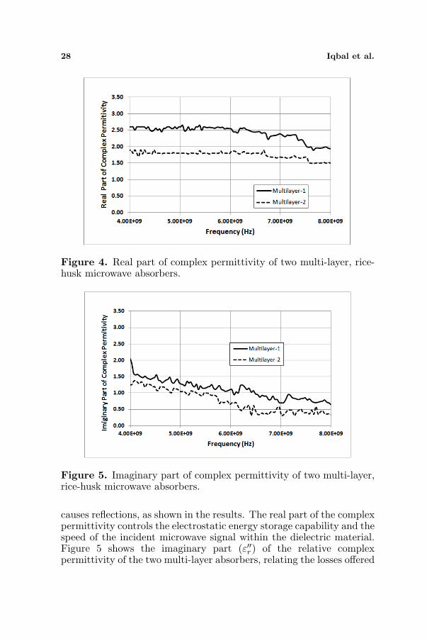
Figure 4 shows the real part (ε′r) of the complex permittivity(εr) of two multi-layer absorbers as measured by using the free-spacetransmission technique. In the free-space method, the whole surfaceof the target is exposed to the incident wave, and the bulk propertiesof the target also affect the results. The non-uniform distribution ofthe constituents in the mixture results in impedance gradients and
Figure 3. Typical free-space transmission coefficient measurementsetup for dielectric characterization of the rice-husk absorber.
28 Iqbal et al.
Figure 4. Real part of complex permittivity of two multi-layer, rice-husk microwave absorbers.
Figure 5. Imaginary part of complex permittivity of two multi-layer,rice-husk microwave absorbers.
causes reflections, as shown in the results. The real part of the complexpermittivity controls the electrostatic energy storage capability and thespeed of the incident microwave signal within the dielectric material.Figure 5 shows the imaginary part (ε′′r) of the relative complexpermittivity of the two multi-layer absorbers, relating the losses offered
Progress In Electromagnetics Research, Vol. 131, 2012 29
by the dielectric material. Usually, complex permittivity is expressedwithout subscript “r” as ε = |ε| e−jδ, where δ is the loss angle that isrelated to another important factor, i.e., tan(δ) = ε′′
ε′ , which describesthe dielectric properties.
3.2. Radar Cross-Section Method
The radar cross-section (RCS) method has been used to evaluate thereflectivity performance of the fabricated absorbers, and the setupis shown in Figure 6. In this method, a reference is calibrated byexposing a metallic surface to a transmitting antenna, and the signalthat is reflected from the metal is measured by another antenna as areceiver. Then, the absorber being tested was placed on the referencesurface, and reflection was measured again. The reflected signalfrom the absorber backed by a reference sample gives the reflectivityof the absorber relative to the reference. An iron-based, metallicplate was used as the backing plate, because, in most cases, largeanechoic chambers are built by high permeability mild steel (MS)or galvanized iron (GI) instead of using non-magnetic sheets. Theferromagnetic nature of the iron-based enclosures with smaller sheetthickness also makes their use possible in low-frequency, magneticshielding. However, other materials, including aluminum and copper,were also investigated in this study. The RCS method requires specialtesting requirements and sample size with respect to the incidentwavelength to avoid edge reflections. In this study, we used a largeabsorber on the back of the metal back plate to focus the entirereflected signal towards the receiving antenna.
(a) (b)
Figure 6. Reflectivity measurements of the graded-impedance, rice-husk microwave absorber inside the anechoic chamber by the RCSmethod. (a) Perforated design. (b) Non-perforated design.
30 Iqbal et al.
3.3. EMI Noise Reduction
The experiment was performed inside the specially-designed, shieldedanechoic chamber to avoid any unintentional noise coupling tothe experimental setup. High-frequency, low-loss, shielded cableswere used to minimize the attenuation of the signal and externalinterference. The distance from the noise source to the receptorplays an important role in noise coupling, so longer shielded cableswere used to isolate the measurement system. Shielded cables areusually immune to incident electric-field noise [5], provided that theyare well grounded. Signal loss introduced by lengthy cables can becompensated by increasing the signal level or by using higher-gainantennas. Noise decoupling was ensured because cables, printed circuitboard (PCB) tracks, and internal wiring could behave as antennasin the electronic hardware, resulting in unintentional coupling ofelectromagnetic fields [19]. The metallic supports used to mount theantennas also were covered by the absorber to avoid reflections, asshown in Figure 6.
3.4. Calibration of the System
In this experiment, an Agilent Network Analyzer E5071C was usedand Figure 7 shows the Network Analyzer before and after two-portTRL calibration. The reference plane of Network Analyzer changeswith the addition of any test fixture or any device under test (DUT).Installation of any piece of coaxial cable, any coax-rectangular adaptor,
(a) (b)
Figure 7. Network analyzer for characterization of the EMC of therice-husk microwave absorber. (a) Before calibration. (b) After two-port calibration.
Progress In Electromagnetics Research, Vol. 131, 2012 31
or any other type of adaptor or antenna at any port causes reflectionsand disturbs the calibration. To eliminate the effect of the test fixtureor DUT, different techniques are used [21], e.g., thru-reflect-line (TRL),short-open-load-thru (SOLT), time gating, and de-embedding. Thecalibration of the Network Analyzer required calibration probes orkits, impedance-matched coaxial cables, and calibration standards.However, in time gating, no calibration kit is used, and the NetworkAnalyzer is operated in the time domain so reflections could beanalyzed and eliminated.
Due to the unavailability of a time gating option in the E5071CNetwork Analyzer, TRL calibration was performed in this study. TRLis a calibration technique in which three standards, i.e., zero-lengththrough (T), open or short reflect (R), and line standards, are used tocalibrate the Network Analyzer [22].
4. ABSORBER DESIGN AND GEOMETRICAL DETAILS
The pyramidal design is the conventional design at high frequenciesfor microwave absorbers. This absorber design, in which the thicknessof the pyramids is at least several wavelengths, offers very goodperformance at high microwave frequencies. At low frequencies thereare wider-angle reflections, but, due to the availability of more-directional antennas at higher frequencies, the levels of the wide-anglereflections can be controlled [23]. To improve the performance of theabsorber, different materials can be used, such as using added tiredust [24], split-ring resonators (SRR) [25–27], electronic band gaps(EBG) [28], and photonic band-gap (PBG) structures [29].
Non-perforated and perforated designs were investigated in thisstudy. These two designs consist of three layers of the rice-huskmaterial with different dielectric properties. Dielectric grading ofthe designed absorbers was achieved during the fabrication phase byvarying the polyester resin content. Multilayer-1 consisted of threelayers of rice husk that were 5 mm thick and consisted of 30%, 40%,and 50% of resin by weight, whereas 25%, 35%, and 45% of resin byweight was used in multilayer-2. Figure 8 shows the multi-layer schemefor two multi-layer, rice-husk absorbers. The resin was mixed manuallyat room temperature before adding an organic peroxide, methyl ethylketone peroxide (MEKP) which is widely used for curing unsaturatedpolyester resins in polymer industry.
The same fabrication process was used for two perforatedabsorbers, i.e., Perforated-1 and Perforated-2. In the perforateddesigns, an array of circular holes was used to investigate the EMC
Table 1. Geometrical details of the impedance-graded, rice-huskmicrowave absorbers.
Designed
Absorbers
Length
(mm)
Width
(mm)
Average
Thickness
(mm)
Number
of Holes
Hole-to-Hole
Distance
(mm)
Average
Hole Size
(mm)
Multilayer -1 300 250 15 - - -
Multilayer -2 300 250 15 - - -
Perforated -1 220 220 15 59 25 3
Perforated -2 220 220 15 59 25 3
(a) (b)
Figure 9. Fabricated rice-husk-based microwave absorbers.(a) Perforated-1 after fabrication. (b) Perforated-2 inside the moldduring the fabrication process.
Progress In Electromagnetics Research, Vol. 131, 2012 33
performance. The average size of each hole was 10 times less than thelowest working wavelength (at 8GHz) to minimize the transmission ofthe incident microwaves through the holes. These holes were similarto an array of dielectric circular waveguides having a length that wasfive times the diameter of the waveguide. Both perforated absorbershad a thickness of 15 mm, which was less than the previously-designedpyramid absorber [3, 25]. Figure 9 shows the two perforated, rice-husk microwave absorbers with circular holes. Table 1 shows thegeometrical details of the four absorbers that were designed. Thicknesswas measured at four points on each side of the absorber, and theaverage of all four sides was used.
5. RESULTS AND DISCUSSION
Experimental results for the reflectivity of the perforated and non-perforated, multiple-layer, planar, rice-husk microwave absorbers wereobtained. It is a common practice to use metallic enclosures forelectromagnetic attenuation, and different standards are available fortheir testing across a broad range of frequencies [30–33]. Microwaveabsorbers also can be characterized in terms of their shieldingeffectiveness [34], but, for the most part, their performance is describedby their reflectivity with respect to a reference metallic plate.
Figure 10. Reflectivity performance of the multi-layer, graded-impedance, rice-husk microwave absorbers at a normal incident angle.
34 Iqbal et al.
5.1. Reflectivity Performance of Rice-husk MicrowaveAbsorber
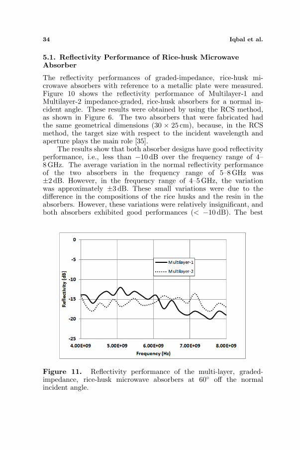
The reflectivity performances of graded-impedance, rice-husk mi-crowave absorbers with reference to a metallic plate were measured.Figure 10 shows the reflectivity performance of Multilayer-1 andMultilayer-2 impedance-graded, rice-husk absorbers for a normal in-cident angle. These results were obtained by using the RCS method,as shown in Figure 6. The two absorbers that were fabricated hadthe same geometrical dimensions (30 × 25 cm), because, in the RCSmethod, the target size with respect to the incident wavelength andaperture plays the main role [35].
The results show that both absorber designs have good reflectivityperformance, i.e., less than −10 dB over the frequency range of 4–8GHz. The average variation in the normal reflectivity performanceof the two absorbers in the frequency range of 5–8 GHz was±2 dB. However, in the frequency range of 4–5 GHz, the variationwas approximately ±3 dB. These small variations were due to thedifference in the compositions of the rice husks and the resin in theabsorbers. However, these variations were relatively insignificant, andboth absorbers exhibited good performances (< −10 dB). The best
Figure 11. Reflectivity performance of the multi-layer, graded-impedance, rice-husk microwave absorbers at 60◦ off the normalincident angle.
Progress In Electromagnetics Research, Vol. 131, 2012 35
Table 2. Average reflectivity performance of two multi-layer,impedance-graded, rice-husk microwave absorbers at normal (0◦) andat 60◦ off the normal incident angle.
performance was obtained at high frequencies for which the ratio ofwavelength to target size had the smallest values.
Figure 11 shows the reflectivity performance of both multi-layer,rice-husk microwave absorbers, when angle of incidence was 60 degreefrom the normal. The results show that both absorbers had goodwide-angle reflectivity performance (< −10 dB) even at 60 from thenormal. Both absorbers had variations of ±3 to ±4 dB at somefrequencies. However, as shown in Table 2, the average of thereflectivity performance was within ±1 dB. In the RCS method ofreflectivity measurement, the sample is placed on the reference metalplate thus, edge diffractions can cause serious errors at angles thatdeviate extensively from the normal angle.
Also, Table 2 shows that the high-frequency performance of thegraded-impedance, rice-husk microwave absorbers was better thanperformance at lower frequencies. At higher frequencies (lowerwavelengths) for which the ratio of thickness to incident wavelengthis greater, the wave dissipates most of its energy during its passagethrough the material.
5.2. Effect of the Back Plate
Three types of reference metal plates, i.e., copper, aluminum, andiron, were investigated, and the results are shown in Figure 12. Allthe reference metallic plates had the same dimensions (30 × 30 cm).The results show that copper and aluminum had the same reflectivityperformance in the frequency range of 4.5–5.5GHz, but, at higherfrequencies, the performance was within ±2 to ±3 dB. Reflectivity of
36 Iqbal et al.
the iron was 2–3 dB greater than that of copper and aluminum inthe frequency range of 4.4–5.8 GHz. At frequencies above 5.8 GHz, thereflectivity of the iron decreased and was comparable to the reflectivityof aluminum, except at the frequencies of 6.2GHz and 7.6 GHz.However, copper had greater reflectivity than either aluminum oriron in the frequency range of 5.9 GHz to 8 GHz. Reflection of themicrowaves by the target depends on the impedance mismatch at theinterface of the two media.
Copper and aluminum are non-magnetic (µr = 1) materials, butiron is a magnetic material with a relative magnetic permeability µr >1. Conductors are considered as perfect reflectors of microwaves, buttheir reflectivity depends on their conductivity [36]. The conductivityof copper is greater than that of aluminum and iron, so it must havelarge reflections. The presence of impurities in the metals affectstheir conductivity and hence their reflectivity. Iron has a strongtendency to corrode readily in moist environment, as compared to thecopper and aluminum. In EMC applications, where iron is used asan electromagnetic shield, corrosion is controlled by measures suchas alloying, painting, or galvanizing with zinc. Corrosion affects thereflection characteristics as well as the shielding effectiveness of theiron by producing an insulating layer on its surface. The non-uniformdistribution of the corrosion reduces the reflection performance of theiron further at higher frequencies.
Figure 12. Reflection loss of different reference metal plates.
Progress In Electromagnetics Research, Vol. 131, 2012 37
5.3. Effect of Perforation
Figure 13 shows the reflectivity performance of the rice-husk,Perforated-1 microwave absorber over the frequency range of 4–8 GHz.The absorber’s reflectivity performance was better than −10 dB atnormal and 60◦ off the normal incident angle. In the frequency range of5.3–8.0GHz, the performance was better than −15 dB, and it increasedwith frequency. The best performance was obtained at normal and at45◦ off the normal incident angle at higher frequencies. There is adecrease in reflectivity performance for 60◦ off the normal at higherfrequencies due to the leakage caused by edge reflections. The rice-husk microwave absorber had 3-mm circular holes, but the size of theholes was very small compared to the working wavelength (10 timessmaller).
There is a periodic mismatch of impedance and a discontinuity inthe dielectric properties of the rice-husk material due to the presenceof holes. These periodic holes behave like multiple scattering centersand cause reflections, as shown in the Figures 13 and 14.
The reflectivity performance of the rice-husk, Perforated-2microwave absorber is shown in Figure 14. There was a decrease inperformance at 60◦ off the normal, but the overall performance wasbetter than −10 dB. The best performance was obtained at the high-frequency end for a normal angle of incident. A maximum variation
Figure 13. Reflectivity performance of the rice-husk, microwave,Perforated-1 absorber.
38 Iqbal et al.
Figure 14. Reflectivity performance of the rice-husk, microwave,Perforated-2 absorber.
of 4 dB was observed in the performance of both absorbers in thefrequency range of 4.0–5.8 GHz at 60◦ off the normal incident angle.Reflectivity performance of both absorbers was comparable for thenormal incidence angle.
5.4. Effect of Seams
Figure 15 shows the alignment of the induced current lines with in theabsorbing material due to the presence of an array of holes and a seam.In this experiment two seams were investigated and the electric-fieldcomponent of the microwave signal was oriented perpendicular to theseams. The seams were generated by placing the two pieces of the samerice-husk absorber at 10 mm and 20mm apart. A seam is actually along narrow slot that may or may not have electrical contact at variouspoints along its length. When electromagnetic signal interacts withthe seam having length l, it behaves like a radiating source whosecomplement is a long wire that looks like a dipole. The length of theslot represents the length of the equivalent complimentary dipole and ifthe length is of the order of λ/2 than it will become an efficient antenna.Therefore in EMC applications, a single lengthy seam is avoided anda linear array of closely spaced apertures or holes is preferred.
Figure 16 presents the degradation of the reflectivity performanceof the absorber due the presence of long seams. The results presentedin Subsection 5.3 also confirm the better reflectivity performance ofarray of closely spaced holes in perforated absorbers.
Progress In Electromagnetics Research, Vol. 131, 2012 39
(b)(a)
(c)
Figure 15. (a) Current distribution due to an array of circularholes. (b) Current distribution due to a single slot. (c) Rice-huskmicrowave absorber with a seam of w = 10 mm, 20 mm, l = 200 mmand t = 15 mm.
Figure 16. Reflectivity performance of the rice-husk, microwaveabsorber with 10-mm and 20-mm seams.
High-frequency, incident waves can pass through the seam easilyand cause reflections from the metal back plate. The results showed
40 Iqbal et al.
large reflections for both seams, especially at high frequencies (5.9–8.0GHz). The presence of the seams created an impedance mismatchand a discontinuity in the dielectric properties of the material at seam’spositions. The results showed a reflectivity difference of ±2 dB to±3 dB between the two seams. Without the seams, the reflectivityperformance of the rice-husk, microwave absorber was better (≤ 9 dB)than the reflectivity performance of both seams in the frequencyrange of 4.0–8.0 GHz. At low frequencies, there was a performancedegradation of 4.0–5.0 dB due to the effects of the seams.However,in the frequency range of 5.8 to 7 GHz, the largest performancedegradation of 5–10 dB was observed due to the large reflections.
6. COMPARISON OF REFLECTIVITY PERFORMANCE
Table 3 shows the reflectivity performance of the graded-impedance,rice-husk, microwave absorbers along with a commercially available flatabsorber (LF-74). In this study, four impedance-graded, microwaveabsorbers were fabricated by using rice husks, polyester, and MEKPhardener. LF-74 is a member of C-RAM LF, a series of lightweightradar absorbers made from graded layers of lossy, open-cell, plasticfoam [37]. Designed absorbers were also investigated for 45◦ obliqueangle reflectivity performance. Average results for oblique anglereflectivity performance of two multilayers and perforated absorbersare also presented for comparison. All the designed impedance-
Table 3. Performance comparison of rice-husk, microwave absorberswith a commercially available (19.1 mm) absorber over the frequencyrange of 4–8GHz.
Progress In Electromagnetics Research, Vol. 131, 2012 41
graded, rice-husk absorbers had good (less than −10 dB) results inthe range of 4–8 GHz even at oblique angle. The performance alsowas comparable to the LF-74 microwave absorber, especially at thehigher-frequency end. However, the fabricated rice-husk, microwaveabsorbers had minimum (but less than −10 dB) performance at lowerfrequencies. Multilayer-1 had its worst performance at 4GHz, but,at higher frequencies, its performance was comparable to that of theothers. The difference in the performance was due to the fact that theLF-74 absorber was thicker (19.1mm) than the rice-husk absorbers.Table 3 also confirms the better performance of graded impedance,microwave, rice-husk absorbers as compared to the non-graded, rice-husks based microwave absorber.
7. CONCLUSIONS
In this paper, we have described the graded-impedance method thatwas used to fabricate rice husk-based, microwave absorbers. Weconducted an experimental investigation of the performance of the rice-husk material to determine its viability for use in future EMC solutions.The experimental results showed that the impedance-graded, rice-husk material in planar geometry also can be used efficiently at lowfrequencies to provide an anechoic environment. Two designs wereinvestigated, i.e., the impedance-graded, multi-layer design and theperforated design, and the results showed that their performanceswere better than-10 dB. This means that the proposed absorbers canabsorb more than 90% of the incident microwave energy. Comparisonswith a commercially-available absorber also confirmed the effectivenessof the impedance-graded, rice-husk material as a good microwave-absorbing candidate for future EMC applications. These absorberscould be a very wise choice for small EMC chambers for which sizeis the main constraint. The prospective future applications of theperforated, rice-husk, microwave absorber may include the lining of themetallic honeycombs that are used for ventilation in shielded anechoicchambers. In future research, these absorbers should be investigatedfor temperature effects, electrical stresses, airflow through perforatedabsorbers, and high-power microwave exposures.
Usually agricultural waste is burned, which increases thepercentage of CO2 in the atmosphere. The use of rice-husk materialas a renewable energy source in the microwave industry certainlycould decrease the harmful ecological contribution (black carbon) ofthis material. Large-scale production of rice husk-based microwaveabsorbers also will provide a cheaper microwave anechoic source.
42 Iqbal et al.
REFERENCES
1. Kartini, K., H. B. Mahmud, and M. S. Hamidah, “Absorption andpermeability performance of Selangor rice husk ash blended grade30 concrete,” Journal of Engineering Science and Technology,Vol. 5, No. 1, 1–16, 2010.
2. Jain, A. K., S. K. Sharma, and D. Singh, “Reaction kinetics ofpaddy husk thermal decomposition,” IECEC-96, Vol. 4, 2274–2279, 1996, 0-7803-3547-3-7/16.
3. Nornikman, H., F. Malek, P. J. Soh, A. A. H. Azremi, F. H. Wee,and A. Hasnain, “Set up and results of pyramidal microwaveabsorbers using rice husks,” Progress In ElectromagneticsResearch, Vol. 111, 141–161, 2011.
4. Chung, B. K. and H. T. Chuah, “Modeling of RF absorberfor application in the design of anechoic chamber,” Progress InElectromagnetics Research, Vol. 43, 273–285, 2003.
5. Schmitt, R., Electromagnetics Explained: A Handbook forWireless/RF, EMC, and High-speed Electronics, Elsevier Science,USA, 2002.
6. Morgan, D., A Handbook for EMC Testing and Measurement,Peter Peregrinus, London, United Kingdom, 1994.
7. Sasagawa, T., O. Hashimoto, S. Watanabe, T. Saito, andH. Kurihara, “Examination on temperature distribution ofa pyramidal EM-wave absorber under high power injection,”Proceedings of Asia-Pacific Microwave Conference, 2007.
8. Ali, I. A. and L. J. Auchterlonie, “Temperature distribution inuniform and layered microwave absorbers in waveguide,” IEEProc., Vol. 130, No. 3, 1983.
9. Ott, H. W., Electromagnetic Compatibility Engineering, JohnWiley & Sons, Inc., Hoboken, New Jersey, 2009.
10. Pozer, D. M., Microwave Engineering, 3rd Edition, John Wiley &Sons, 2005.
11. Tong, X. C., Advanced Materials and Design for ElectromagneticInterference Shielding, CRC Press, Taylor & Francis Group,Broken Sound Parkway NW, Suite 300, Boca Raton, 2009.
12. Kumar, S. B., U. Raveendranath, P. Mohanan, K. T. Mathew,M. Hajian, and L. P. Ligthart, “A simple free-space methodfor measuring the complex permittivity of single and compounddielectric materials,” Microwave and Optical Technology Letters,Vol. 26, No. 2, Jul. 2000.
13. Helme, B. G., “Measurements of the microwave properties of
Progress In Electromagnetics Research, Vol. 131, 2012 43
materials,” IEEE Colloquium on Industrial Uses of Microwaves,1–7, 1990.
14. Williams, N., V. K. Varadan, D. Ghodgaonkar, andV. V. Varadan, “Measurement of transmission and reflectionof conductive lossy polymers at millimeter-waves frequencies,”IEEE Transaction on Electromagnetic Compatibility, Vol. 32,No. 3, 236–240, Aug. 1990.
15. Barker-Jarvis, J., et al., “Dielectric characterization of low-lossmaterials-A comparison of techniques,” IEEE Trans. Dielectric.Electr. Insul., Vol. 5, No. 4, 571–577, Aug. 1998.
16. Trabelsi, S. and S. O. Nelson, “Calibration methods fornondestructive microwave sensing of moisture content and bulkdensity of granular materials,” Transactions of the ASAE, Vol. 47,No. 6, 1999–2008, 2004.
17. Trabelsi, S. and S. O. Nelson, “Nondestructive sensing of bulkdensity and moisture content in shelled peanuts from microwavepermittivity measurements,” Food Control, Vol. 17, 304–311,Elseveir, 2006.
18. Trabelsi, S., A. W. Kraszewski, and S. O. Nelson, “Phase-shift ambiguity in microwave dielectric properties measurements,”IEEE Transactions on Instrumentation and Measurement, Vol. 49,No. 1, Feb. 2000.
20. Jose, K. A., V. V. Varadan, and V. K. Varadan, “Free-space vs. one horn interferometer techniques for radar absorbermeasurements,” Microwave Journal, 1998.
21. Rolfes, I. and B. Schiek, “Calibration methods for microwave freespace measurements,” Advances in Radio Science 2, 19–25, 2004.
23. Chung, B. K. and H. T. Chuah, “Design and construction of amultipurpose wideband anechoic chamber,” IEEE Antennas andPropagation Magazine, Vol. 45, No. 6, Dec. 2003.
24. Malek, F., E. M. Cheng, O. Nadiah, H. Nornikman, M. Ahmed,M. Z. A. A. Aziz, A. R. Othman, P. J. Soh, A. A. H. Azremi,A. Hasnain, and M. N. Taib, “Rubber tire dust-rice huskpyramidal microwave absorber,” Progress In ElectromagneticsResearch, Vol. 117, 449–477, 2011.
25. Nornikman, H., B. H. Ahmad, M. Z. A. A. Aziz, F. Malek,H. Imran, and A. R. Othman, “Study and simulation of an edge
44 Iqbal et al.
couple split ring resonator (EC-SRR) on truncated pyramidalmicrowave absorber,” Progress In Electromagnetics Research,Vol. 127, 319–334, 2012.
26. Ren, L. S., Y. C. Jiao, J.-J. Zhao, and F. Li, “RCS reductionfor a fss-backed reflectar-ray using a ring element,” Progress InElectromagnetics Research Letters, Vol. 26, 115–123, 2011.
27. Lee, H. M. and H. S. Lee, “A dual band metamaterialabsorber based with resonant-magnetic structures,” Progress InElectromagnetics Research Letters, Vol. 33, 1–12, 2012.
28. Elsheakh, D. N., H. A. Elsadek, E. A. Abdallah, M. F. Iskander,and H. Elhenawy, “Ultra wide bandwidth umbrella-shaped microstrip monopole antenna using spiral artificial magnetic conductor(SAMC),” IEEE Antennas and Wireless Propagation Letters,Vol. 8, 1255–1258, 2009.
29. Yiqiang, W. and F. Tao, “The study on a patch antenna withPBG structure,” Third International Symposium on IntelligentInformation Technology Application, Vol. 3, 565–567, 2009.
30. Hemming, L. H., Electromagnetic Anechoic Chambers a Fun-damental Design and Specification Guide, IEEE Press, Wiley-Interscience, 2002.
31. Hemming, L. H., Architectural Electromagnetic Shielding Hand-book, IEEE Press, New York, 1992.
32. IEEE 299–1997, “IEEE standard method of measuring theeffectiveness of electromagnetic shielding enclosures,” 1997.
33. NSA 94-106, National Security Agency Specification for RFShielded Enclosures: General Specifications, Oct. 24, 1994.
34. Koledintseva, M. Y., A. G. Razmadze, A. Y. Gafarov,V. V. Khilkevich, J. L. Drewniak, and T. Tsutaoka, “Attenuationin extended structures coated with thin magneto-dielectricabsorber layer,” Progress In Electromagnetics Research, Vol. 118,441–459, 2011.
35. Hiatt, R. E., et al., “A study of VHF absorbers and anechoicrooms,” Report 5391-I-f, University of Michigan, Feb. 1963.
36. Zhou, L., W. Wen, C. T. Chan, and P. Sheng, “Reflectivity ofplanar metallic fractal patterns,” Applied Physics Letters, Vol. 82,Feb. 17, 2003.
37. “C-Ram LF and LF-W flexible foam sheet broadband microwaveabsorber,” Technical Bulletin 320-1, 2008, www.cumingmw.com,Document Control No. N-07-000-01353-3.