Date post: | 28-Oct-2015 |
Category: |
Documents |
Upload: | chen-wai-peng |
View: | 30 times |
Download: | 1 times |
7/30/13 A Study On Cable Suspension Footbridge
www.nbmcw.com/articles/bridges/933-a-study-on-cable-suspension-footbridge.html 1/3
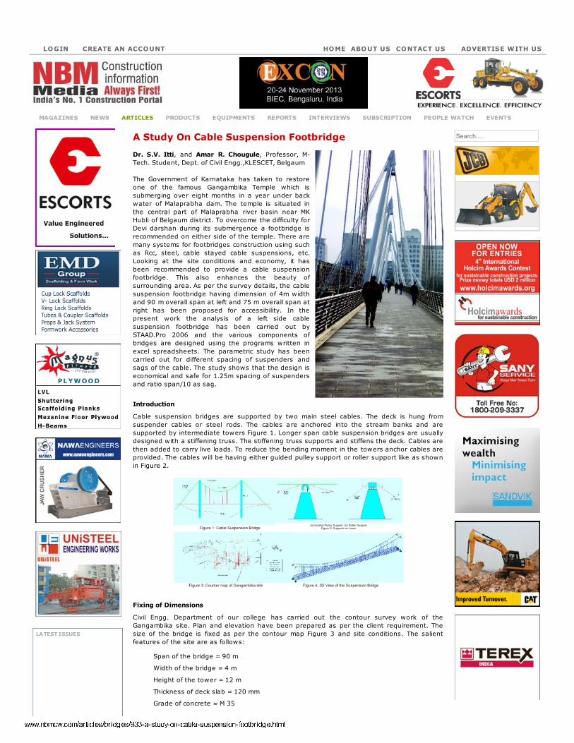
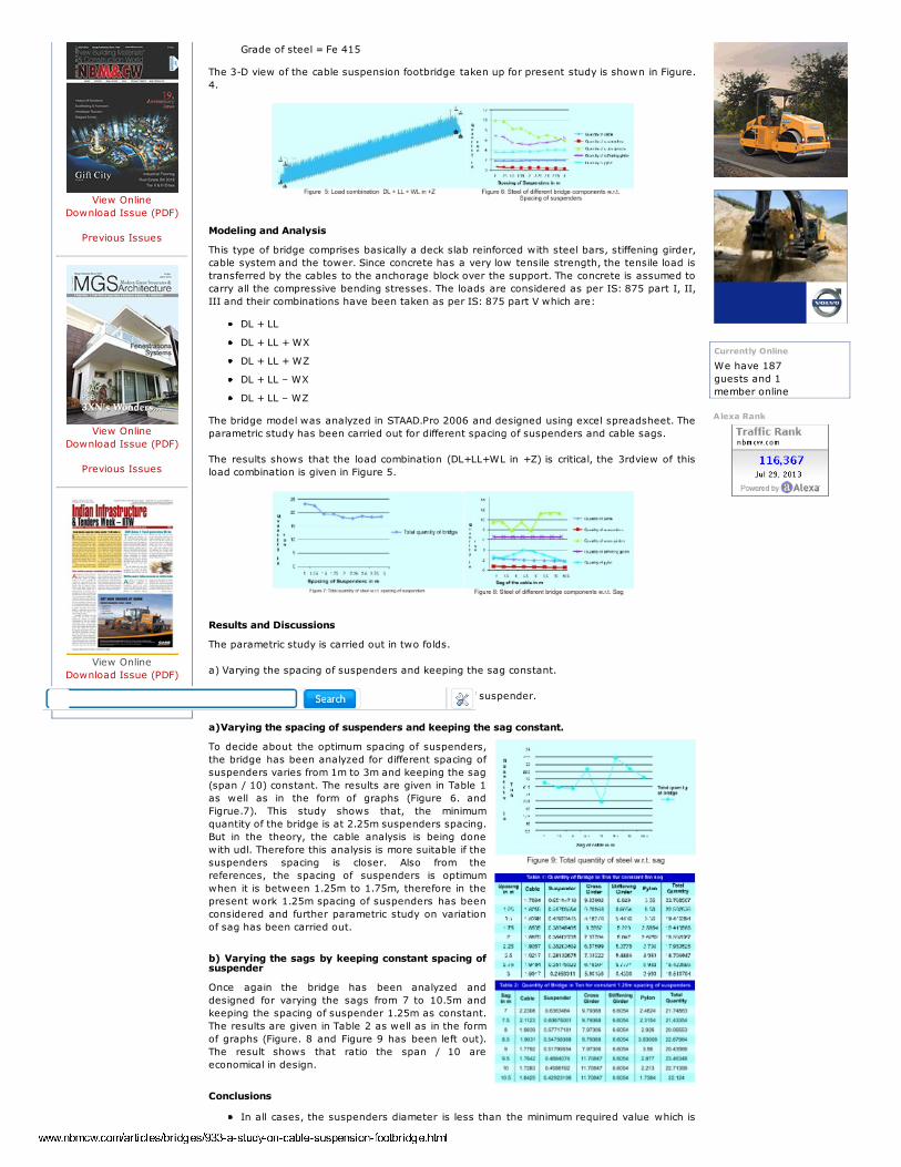
LOGIN CREATE AN ACCOUNT ADVERTISE WITH USCONTACT USABOUT USHOME
A Study On Cable Suspension Footbridge
Dr. S.V. Itti, and Amar R. Chougule, Professor, M-
Tech. Student, Dept. of Civil Engg.,KLESCET, Belgaum
The Government of Karnataka has taken to restore
one of the famous Gangambika Temple which is
submerging over eight months in a year under back
water of Malaprabha dam. The temple is situated in
the central part of Malaprabha river basin near MK
Hubli of Belgaum district. To overcome the difficulty for
Devi darshan during its submergence a footbridge is
recommended on either side of the temple. There are
many systems for footbridges construction using such
as Rcc, steel, cable stayed cable suspensions, etc.
Looking at the site conditions and economy, it has
been recommended to provide a cable suspension
footbridge. This also enhances the beauty of
surrounding area. As per the survey details, the cable
suspension footbridge having dimension of 4m width
and 90 m overall span at left and 75 m overall span at
right has been proposed for accessibility. In the
present work the analysis of a left side cable
suspension footbridge has been carried out by
STAAD.Pro 2006 and the various components of
bridges are designed using the programs written in
excel spreadsheets. The parametric study has been
carried out for different spacing of suspenders and
sags of the cable. The study shows that the design is
economical and safe for 1.25m spacing of suspenders
and ratio span/10 as sag.
Introduction
Cable suspension bridges are supported by two main steel cables. The deck is hung from
suspender cables or steel rods. The cables a re anchored into the stream banks and are
supported by intermediate towers Figure 1. Longer span cable suspension bridges are usually
designed with a stiffening truss. The stiffening truss supports and stiffens the deck. Cables are
then added to carry live loads. To reduce the bending moment in the towers anchor cables are
provided. The cables will be having either guided pulley support or roller support like as shown
in Figure 2.
Fixing of Dimensions
Civil Engg. Department of our college has carried out the contour survey work of the
Gangambika site. Plan and elevation have been prepared as per the client requirement. The
size of the bridge is fixed as per the contour map Figure 3 and site conditions. The salient
features of the site are as follows:
Span of the bridge = 90 m
Width of the bridge = 4 m
Height of the tower = 12 m
Thickness of deck slab = 120 mm
Grade of concrete = M 35
Search.....
LATEST ISSUES
MAGAZINES NEWS ARTICLES PRODUCTS EQUIPMENTS REPORTS INTERVIEWS SUBSCRIPTION PEOPLE WATCH EVENTS
7/30/13 A Study On Cable Suspension Footbridge
www.nbmcw.com/articles/bridges/933-a-study-on-cable-suspension-footbridge.html 2/3
View Online
Download Issue (PDF)
Previous Issues
View Online
Download Issue (PDF)
Previous Issues
View Online
Download Issue (PDF)
Previous Issues
Grade of steel = Fe 415
The 3-D view of the cable suspension footbridge taken up for present study is shown in Figure.
4.
Modeling and Analysis
This type of bridge comprises basically a deck slab reinforced with steel bars, stiffening girder,
cable system and the tower. Since concrete has a very low tensile strength, the tensile load is
transferred by the cables to the anchorage block over the support. The concrete is assumed to
carry all the compressive bending stresses. The loads are considered as per IS: 875 part I, II,
III and their combinations have been taken as per IS: 875 part V which are:
DL + LL
DL + LL + WX
DL + LL + WZ
DL + LL – WX
DL + LL – WZ
The bridge model was analyzed in STAAD.Pro 2006 and designed using excel spreadsheet. The
parametric study has been carried out for different spacing of suspenders and cable sags.
The results shows that the load combination (DL+LL+WL in +Z) is critical, the 3rdview of this
load combination is given in Figure 5.
Results and Discussions
The parametric study is carried out in two folds.
a) Varying the spacing of suspenders and keeping the sag constant.
b) Varying the sags and keeping constant spacing of suspender.
a)Varying the spacing of suspenders and keeping the sag constant.
To decide about the optimum spacing of suspenders,
the bridge has been analyzed for different spacing of
suspenders varies from 1m to 3m and keeping the sag
(span / 10) constant. The results are given in Table 1
as well as in the form of graphs (Figure 6. and
Figrue.7). This study shows that, the minimum
quantity of the bridge is at 2.25m suspenders spacing.
But in the theory, the cable analysis is being done
with udl. Therefore this analysis is more suitable if the
suspenders spacing is closer. Also from the
references, the spacing of suspenders is optimum
when it is between 1.25m to 1.75m, therefore in the
present work 1.25m spacing of suspenders has been
considered and further parametric study on variation
of sag has been carried out.
b) Varying the sags by keeping constant spacing ofsuspender
Once again the bridge has been analyzed and
designed for varying the sags from 7 to 10.5m and
keeping the spacing of suspender 1.25m as constant.
The results are given in Table 2 as well as in the form
of graphs (Figure. 8 and Figure 9 has been left out).
The result shows that ratio the span / 10 are
economical in design.
Conclusions
In all cases, the suspenders diameter is less than the minimum required value which is
We have 187
guests and 1
member online
Currently Online
Alexa Rank
7/30/13 A Study On Cable Suspension Footbridge
www.nbmcw.com/articles/bridges/933-a-study-on-cable-suspension-footbridge.html 3/3
TERMS & CONDITIONS PRIVACY POLICY CANCELLATION/REFUND POLICY DISCLAIMER
Copyright © 2010 NBM Media Pvt. Ltd. All Rights Reserved.
10mm.
The quantity of cable steel has larger variation with respect to the spacing of
suspenders.
1.25m spacing of suspenders and cable sag equals span / 10 gives the economical
design of footbridge.
References
Technical Papers
A dissertation submitted to the SWISS Federal Institute of Technology Zurich for the
degree of Doctor of Sciences ETH” by Pietro Pedrozzi
Steinman, D. B. – “A practical Treatise on Suspension Bridges” by John Wiley and Sons,
Inc., New York.
Willard G. Bouricius, Philip K. Wittman, - “DESIGNING CANOPY WALKWAYS,” Bart Bouricius,
Canopy Construction Associates, - 32 Mountain View Circle, Amherst, MA 01002, FL
32835-5137, MA 01002.
FOOTBRIDGES,” A Manual for Construction at Community and District Level, I.T. Transport
Ltd. Consultants in Transport for Development. June 2004.
Peters, Tom F., - “Transitions in Engineering: Guillaume Henri Dufour and the Early 19th
Century Cable Suspension Bridges,” Birkhauser, 1987, ISBN 3764319291.
IS Codes
IS 456-2000 “Plain and Reinforced Concrete - Code of Practice (Fourth Revision)
SP 16:1980 “Design Aids for Reinforced Concrete to IS 456- 2000”
Books
Steinman, D. B. – “A practical Treatise on Suspension Bridges” by John Wiley and Sons,
Inc., New York.
Niels J. Gimsing, “Cable Supported Bridges – Concept and Design,” A Wily Interscience
Publication, technical university of Denmark.
Dr. B.C. Punmia, Ashok Kumar Jain and Arun Kumar Jain-2003, “Reinforced Concrete
Structures (Vol.1),” Laxmi Publications (P) Ltd.
Dr. Shah and Karve, “Limit State Theory and Design of Reinforced Concrete,” Structures
Publications.
NBMCW February 2009
< Prev Next >