6th CIRP International Conference on High Performance Cutting, HPC2014
A study on PCD tool surface reconditioning technique for SiC micromachining
Shogo Takesuea, Kazutoshi Katahirab*, Jun Komotoric a Graduate School of Science and Technology, Keio University, 3-14-1 Hiyoshi, Kohoku-ku, Yokohama-shi, Kanagawa, Japan
bMaterials Fabrication Laboratory, RIKEN, 2-1, Hirosawa, Wako-shi, Saitama, Japan c Department of Mechanical Engineering, Keio University, 3-14-1 Hiyoshi, Kohoku-ku, Yokohama-shi, Kanagawa, Japan
In this study, ultra-precision machining using a polycrystalline diamond (PCD) micro end mill was carried out on high-purity silicon carbide. The machined surface was observed using scanning electron microscopy, and the three-dimensional surface profile and surface roughness were measured using scanning interferometry. In addition, an elemental analysis of PCD tool surface was performed using energy dispersive X-ray spectrometry (EDX). It was found that a smooth surface with nanometer-scale roughness was obtained when the undeformed chip thickness was small enough to achieve ductile mode machining. However, nanometer-sized chips produced during machining adhered to the PCD tool surface, and were difficult to be removed using conventional methods such as ultrasonic cleaning. An EDX analysis showed that the adhered material was silicon dioxide. In order to remove it, a tool surface reconditioning technique was developed, based on electrolytic treatment using sodium hydroxide and the generation of hydroxide ions. The results indicated that this was effective at removing the adhered material, and led to a recovery of the performance of the PCD tool.
Silicon carbide (SiC) molds are used for manufacturing glass products such as aspherical lenses and micro total analysis systems ( TAS) because of its high wear resistance and thermal stability. On the other hand, SiC is known to be a difficult-to-machine material due to its hardness and brittleness, and there are increasing demands for a machining method that can produce the required surface quality and geometric accuracy [1]. Generally, hard brittle materials such as SiC are machined by grinding and polishing in order to achieve a high-quality surface [2,3]. However, these methods have limitations when attempting to create fine complex structures. Turning is another machining approach that has been applied to SiC [4]. However, although this method is
suitable for creating rotationally symmetric structures such as lens molds, it is difficult to produce asymmetric structures such as microchannels. Micro-milling has been shown to be an effective technique for fabricating three-dimensional structures in hard brittle materials, especially when a polycrystalline diamond (PCD) tool is used [5-7]. However, one problem concerns the adhesion to the PCD tool surface of nanometer-sized chips generated during the machining process[8,9]. It is therefore important to develop an effective method for removal of such adhered material.
In this study, ultra-precision machining using a PCD end mill was carried out on high-purity SiC. Moreover, a tool reconditioning technique was developed to effectively remove material adhered to the PCD tool surface, and the underlying mechanism was investigated.
The machine tool used in this study was a linear-motor-drive ultra-precision machine with an air turbine spindle, three linear axes (X, Y, Z), and two angular axes (A, C), which rotate on X and Z axis, respectively. The positioning resolution of this machine is 1 nm.
The workpiece material was high-purity bulk SiC produced by chemical vapor deposition (CVD). The properties of this material are shown in Table 1. It exhibits higher purity and homogeneity than conventional sintered SiC. The dimensions of the workpiece were 10 mm x 10 mm x 5 mm.
Micro-milling was performed using a PCD end mill, as shown in Fig. 1, with a diameter of 1 mm and six flutes. The experimental setup is shown in Fig. 2, and the milling conditions are listed in Table 2.
The machined surface was observed using scanning electron microscopy (SEM). In addition, 3D surface profiles were obtained using scanning interferometry, and average surface roughness Ra and maximum height roughness Rz were determined within an area of 144 m x 108 m. After machining, PCD tool surfaces were also observed using SEM and an elemental analysis was performed using energy dispersive X-ray spectrometry (EDX).
Table 1 Properties of high-purity SiC
Fig. 1. PCD end mill used in experiment
Fig. 2. Experimental setup
Table 2 Milling conditions
3. Results and discussions
3.1. Effect of milling on SiC surface
Figure 3 shows SEM images of the workpiece surface before and after milling. Before milling (Fig. 3(a)), the surface roughness values Ra and Rz were about 0.3 m and 3.6 m, respectively. After milling at an undeformed chip thickness of 100 nm, no defects were observed in the SEM image (Fig. 3(b)).
Figure 4 shows a 3D profile of the machined surface. A cutter mark, which is attributed to plastic flow, can be seen, indicating that ductile mode machining was achieved [10]. The Ra and Rz values were determined to be 2.0 nm and 14.2 nm, respectively, indicating that nanoscale roughness was achieved at the beginning of the milling process when the undeformed chip thickness was small enough to machine in ductile mode. These surface roughness values are comparable to those obtained following grinding and polishing of CVD-grown SiC [11].
However, as shown in Fig. 5, the surface roughness increased with cutting distance, and for a cumulative cutting distance of about 1000 mm, the Ra value was over 10 nm.
Fig. 3. SEM images of machined surface (a) before milling (b) after milling
Fig. 4. 3D profile of machined surface
Fig. 5. Dependence of surface roughness on cutting distance
3.2. Effect of milling on PCD tool surface To determine the reason for the increase in surface
roughness with cutting distance, the surface of the PCD tool was investigated. Figure 6 shows SEM images of the tool after milling. It is seen to be covered by a layer of adhered material with a thickness of approximately 10 m. Figure 7 shows SEM images of PCD tool edge before and after milling. From these images, it can be concluded that nanometer-sized chips generated during the machining process accumulated on the cutting edge, thereby leading to a decrease in performance. Figure 8 shows the results of an EDX analysis carried out at Points A and B in Fig. 7. Before milling (Point A), only carbon and cobalt were detected, the former from the diamond abrasives and the latter from the binder material. However, after milling (Point B), silicon and oxygen were also detected. The adhered material can therefore be assumed to be silicon dioxide (SiO2), formed by the reaction:
2SiC + 3O2 → 2SiO2 + 2CO. (1)
Fox reported that CVD-SiC became oxidized at 1200°C
[12]. Moreover, based on molecular dynamics simulations of single-point diamond turning of SiC, Goel et. al. determined that the chip temperature could rise to about 1200 C [13]. Thus, in the present study, it is considered that during machining, the temperature became sufficiently high for the SiC to be oxidized to form SiO2.
3.3. Reconditioning of PCD tool surface using electrolytic technique
Generally, removal of material adhered to a tool surface is
carried out by brushing or by ultrasonic cleaning in an acetone solution. However, in the case of a micro-tool, it is difficult to fully remove it using the above physical approaches. Therefore, in the present study, a chemical etching process was applied.
This was carried out using sodium hydroxide (NaOH) solution, which is an anisotropic etchant for silicon. However, the SiO2 etching rate using a NaOH solution is very low [14],
Fig. 6. SEM images of PCD tool after milling Fig. 7. SEM image of PCD tool edge (a) before milling (b) after milling
Fig. 8. EDX analysis of PCD tool edge (a) before milling (Point A) (b) after
milling (Point B) (at. %) and amethod such as heating, vibration or electrolytic assistance is required in order to accelerate the chemical reaction. Due to its simplicity, an electrolytic treatment was used in this study.
The electrolytic vessel is shown in Fig. 9, in which a carbon brush and a copper plate were used as the anode and cathode, respectively. The cover of the vessel was an acrylic plate so that the solution level could be seen. As shown in Fig. 9(c), reconditioning of the tool could be performed without removing it from the milling machine.
The following reconditioning procedure was used. NaOH solution was poured into the vessel until the PCD tool tip was immersed. The anode was connected to the tool shank, the cathode was immersed in NaOH solution, and a direct current
Fig. 9. Developed electrolytic system (a) electrolytic vessel (b) schematic
illustration of electrolytic method (c) machine tool reconditioning
was applied. This caused a positive voltage to be applied to the PCD tool tip because, although the diamond is an insulator, the Co binder conducts electricity. The electrolytic treatment test conditions are shown in Table 3.
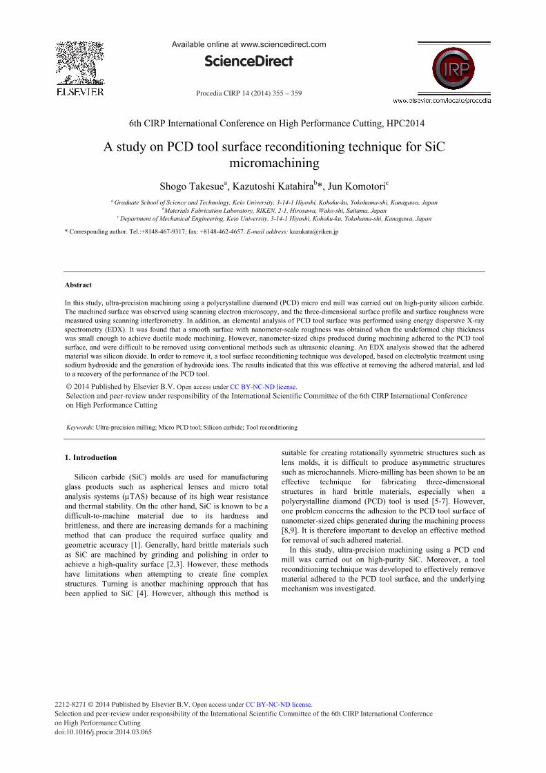
Figure 10 shows SEM images of the same PCD tool edge shown in Fig. 7(b), after 30, 60, 90 and 120 s of electrolytic treatment. It can be seen that the adhered material is gradually removed with increasing treatment time, and has almost fully disappeared after 120 s. Figure 11 shows an EDX spectrum from Point C in Fig. 10(d). Although some Si is still present, the amount is quite small compared to that shown in Fig. 8. Therefore, the majority of the SiO2 was removed. The O peak is due to both residual SiO2 and Co oxide formed during the electrolytic treatment.
Since electrochemical reactions are influenced by a number of different factors, further experiments are required to optimize conditions such as the electrolyzing time, electrical conductivity, pH value, and chemical components of the solution.
Table 3 Electrolytic treatment test conditions
Fig.10. SEM images of PCD tool edge following electrolytic treatment for (a) 30 s (b) 60 s (c) 90 s (d) 120 s
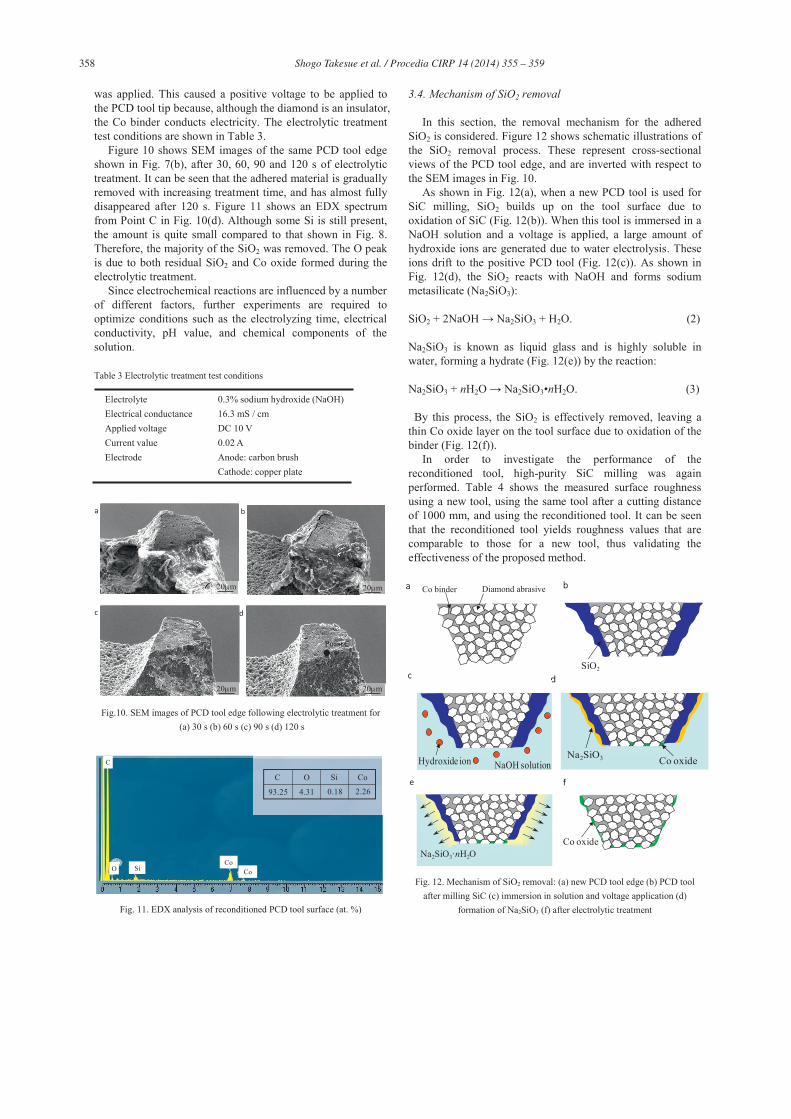
3.4. Mechanism of SiO2 removal In this section, the removal mechanism for the adhered
SiO2 is considered. Figure 12 shows schematic illustrations of the SiO2 removal process. These represent cross-sectional views of the PCD tool edge, and are inverted with respect to the SEM images in Fig. 10.
As shown in Fig. 12(a), when a new PCD tool is used for SiC milling, SiO2 builds up on the tool surface due to oxidation of SiC (Fig. 12(b)). When this tool is immersed in a NaOH solution and a voltage is applied, a large amount of hydroxide ions are generated due to water electrolysis. These ions drift to the positive PCD tool (Fig. 12(c)). As shown in Fig. 12(d), the SiO2 reacts with NaOH and forms sodium metasilicate (Na2SiO3):
SiO2 + 2NaOH → Na2SiO3 + H2O. (2)
Na2SiO3 is known as liquid glass and is highly soluble in water, forming a hydrate (Fig. 12(e)) by the reaction:
Na2SiO3 + nH2O → Na2SiO3•nH2O. (3)
By this process, the SiO2 is effectively removed, leaving a
thin Co oxide layer on the tool surface due to oxidation of the binder (Fig. 12(f)).
In order to investigate the performance of the reconditioned tool, high-purity SiC milling was again performed. Table 4 shows the measured surface roughness using a new tool, using the same tool after a cutting distance of 1000 mm, and using the reconditioned tool. It can be seen that the reconditioned tool yields roughness values that are comparable to those for a new tool, thus validating the effectiveness of the proposed method.
Fig. 12. Mechanism of SiO2 removal: (a) new PCD tool edge (b) PCD tool
after milling SiC (c) immersion in solution and voltage application (d) formation of Na2SiO3 (f) after electrolytic treatment
Table 4 Surface roughness for different tool conditions
4. Conclusion
In this study, micro-milling using a PCD end mill was conducted on high-purity CVD-SiC. It was found that the tool performance decreased with increasing cutting distance due to a buildup of foreign material on the tool surface. An electrolytic technique was developed for reconditioning the tool, and the mechanism involved in the removal of the adhered material was determined. The following results were obtained. • Although machining high-purity SiC using a PCD end mill
could produce smooth surfaces with nanometer-scale roughness, the roughness gradually increased with cutting distance.
• During the machining process, nanometer-sized chips became adhered to the PCD tool surface. From the results of an EDX analysis, this material was assumed to be SiO2.
• The adhered SiO2 was effectively removed using a newly developed electrolytic reconditioning technique, involving a chemical reaction between SiO2 and NaOH.
• The performance of the reconditioned PCD tool was comparable to that of a new tool.
Acknowledgements
The authors would like to thank NS Tool Co., Ltd. for providing PCD tools and advice concerning experiments.
References
[1] D. Dornfeld, S. Min, Y. Takeuchi : Recent Advances in Mechanical Micromachining, Annals of the CIRP, 55 (2006), pp. 745-768
[2] L. Yin, E. Y. Vancoille, L. C. Lee, H. Huang, K. Ramesh, X. D. Liu : High-quality grinding of polycrystalline silicon carbide spherical surfaces, Wear, 256 (2004), pp. 197-207.
[3] F. Klocke, R. Zunke : Removal mechanisms in polishing of silicon based advanced ceramics, Annals of the CIRP, 58 (2009), pp. 491-494.
[4] J. Yan, Z. Zhang, T. Kuriyagawa : Tool wear control in diamond turning of high-strength mold materials by means of tool swinging, Annals of the CIRP, 59 (2010), pp. 109-112.
[5] H. Suzuki, T. Moriwaki, Y. Yamamoto, Y. Goto : Precision Cutting of Aspherical Ceramic Molds with Micro PCD Milling Tool, Annals of the CIRP, 56 (2007), pp. 131-134.
[6] X. Cheng, K. Nakamoto, M. Sugai, S. Matsumoto, Z. G. Wang, K. Yamazaki: Development of ultra-precision machining system with unique wire EDM tool fabrication system for micro/nano-machining, Annals of the CIRP, 57 (2008), pp. 415-420.
[7] Z. Zhang, H. Peng, J. Yan : Micro-cutting characteristics of EDM fabricated high-precision polycrystalline diamond tools, International Journal of Machine Tools & Manufacturing, 65 (2013), pp. 99-106.
[8] K. Katahira, K. Nakamoto, P. Fonda, H. Ohmori, K. Yamazaki : A novel technique for reconditioning polycrystalline diamond tool surfaces applied for silicon micromachining, Annals of the CIRP, 60 (2011), pp. 591-594.
[9] K. Nakamoto, K. Katahira, H. Ohmori, K. Yamazaki, T. Aoyama : A study on the quality of micro-machined surfaces on tungsten carbide generated by PCD micro end-milling, Annals of the CIRP, 61 (2012), pp. 567-570.
[10] T. G. Bifano, T. A. Dow, R. O. Scattergood : Ductile-Regime Grinding : A New Technology For Machining Brittle Materials, Transactions of the ASME, 113 (1991), pp. 184-189.
[11] S. Yin, W. Lin, H. Ohmori, Y. Uehara, M. Asami : Study on ultraprecision synergistic finishing process of ELID-grinding and MRF 2nd Report : Finishing characteristics of CVD-SiC, Journal of the Japan Society for Abrasive Technology, 50 (2006), pp. 324-327.(in Japanese)
[12] D. S. Fox : Oxidation Behavior of Chemically-Vapor Deposited Silicon Carbide and Silicon Nitride from 1200° to 1600°, Journal of the American Ceramic Society, 81 (1998), pp. 945-950.
[13] S. Goel, X. Luo, R. L. Reuben : Molecular dynamics simulation model for the quantitative assessment of tool wear during single point diamond turning cubic silicon carbide, Computation Material Science, 51 (2012), pp. 402-408.
[14] H. Seidel, L. Csepregi, A. Heuberger, H. Baumgartel : Anisotropic Etching of Crystalline Silicon in Alkaline Solutions, Journal of The Electrochemical Society, 137 (1990), pp. 3612-3626.
Average surface roughness Ra, nmMaximum height roughness Rz, nm