A study on the Design Strength of Linear supports * Oh-Hyun Kwon 1) , Hyun-Seob Youn 2) and Dong-Hyun Seo 3) 1) Geotechnical Department, Pyunghwa Engineering Consultants, Korea [email protected]2) Vice-President, SeoHyun Engineering, Korea 3) President, Hyun Engineering and Construction, Korea ABSTRACT Generally, in order to secure the stability of tunnels, main supports such as shotcrete, linear supports, steel reinforcing materials, wire mesh, etc. and tunnel auxiliary method such as umbrella arch method and fore-poling method, etc. are used. Among them, rock bolts or nails are used as linear supports. Linear supports are used in various ground conditions because it is an important supporting material for positively utilizing the support function of the natural ground, it should be designed and constructed considering the interaction effect on the ground so that it can be fully integrated with the ground and its effect can be fully developed. The linear support material is advantageous when elongation rate is as high as possible at break and the elongation of the linear support material is larger than the strain at failure of the rocks and the soil of the ground. By using a material having a higher elongation than that of the ground, sufficient deformation occurs even after the yield strength is developed, so that when the tunnel collapses, the ground is breakdown preferentially. In this case, the linear support does not break. Therefore, it is necessary to review the appropriateness of applying the allowable strength of the linear support to the design strength. In this study, we analyzed the behavior of support materials at the time of tunnel failure using numerical method and investigated the possibility of application of yield strength to design strength of linear support. As a result of the numerical analysis, it is evaluated more reasonable and economical to apply the yield strength instead of the allowable strength as the design strength of the linear support. 1. Introduction Among the main support materials commonly used in tunnels, linear support materials such as rock bolts or nails are used. The linear support material is advantageous when elongation rate is higher than the strain rate at the time of failure of the ground as much as possible. Since the support material is sufficiently deformed while exhibiting the yield strength so that the linear support material can endure after the failure of the ground during the tunnel collapse. Among the linear support materials
Transcript
A study on the Design Strength of Linear supports
* Oh-Hyun Kwon1), Hyun-Seob Youn2) and Dong-Hyun Seo3)
1)Geotechnical Department, Pyunghwa Engineering Consultants, Korea
3)President, Hyun Engineering and Construction, Korea
ABSTRACT
Generally, in order to secure the stability of tunnels, main supports such as shotcrete, linear supports, steel reinforcing materials, wire mesh, etc. and tunnel auxiliary method such as umbrella arch method and fore-poling method, etc. are used. Among them, rock bolts or nails are used as linear supports. Linear supports are used in various ground conditions because it is an important supporting material for positively utilizing the support function of the natural ground, it should be designed and constructed considering the interaction effect on the ground so that it can be fully integrated with the ground and its effect can be fully developed.
The linear support material is advantageous when elongation rate is as high as possible at break and the elongation of the linear support material is larger than the strain at failure of the rocks and the soil of the ground. By using a material having a higher elongation than that of the ground, sufficient deformation occurs even after the yield strength is developed, so that when the tunnel collapses, the ground is breakdown preferentially. In this case, the linear support does not break. Therefore, it is necessary to review the appropriateness of applying the allowable strength of the linear support to the design strength. In this study, we analyzed the behavior of support materials at the time of tunnel failure using numerical method and investigated the possibility of application of yield strength to design strength of linear support. As a result of the numerical analysis, it is evaluated more reasonable and economical to apply the yield strength instead of the allowable strength as the design strength of the linear support. 1. Introduction
Among the main support materials commonly used in tunnels, linear support materials such as rock bolts or nails are used. The linear support material is advantageous when elongation rate is higher than the strain rate at the time of failure of the ground as much as possible. Since the support material is sufficiently deformed while exhibiting the yield strength so that the linear support material can endure after the failure of the ground during the tunnel collapse. Among the linear support materials
of the tunnels, the rock bolts have diameter D22 ~ 29mm and strength SD350 ~ SD400 according to the ground conditions, SD350 has a minimum elongation of 18% and SD400 has a minimum elongation of 16%. And pre-supported nail has a diameter of D29mm or more, the strength SD400 ~ SD600 is used and the minimum elongation of SD600 is 10%.
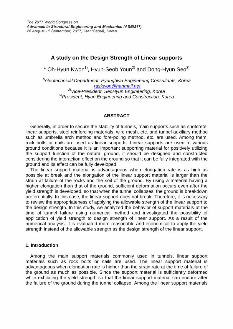
The linear support can be expressed by the behavior of elasto-plasticity equations and the soil is expressed by the Mohr-Coulomb's strength equation, in the stress-strain relationship diagram, the strain at failure of the ground is higher than the yield strength of the linear support at 0.2% (SD400) and less than the minimum elongation at reinforcement of 16% (SD400)(Exclude soft clay, Fig. 1). In other words, since the elongation rate is much larger than the strain of the ground, the reinforcement is not broken at any time when the tunnel collapses (Dong-hyun Seo, 2012). Therefore, if the allowable strength of the linear support is considered as the design strength despite the absence of the damage of the material, it becomes uneconomical over design. In this study, the applicability of the allowable strength of linear support to the design strength was examined using MIDAS NX, finite element numerical analysis software.
Figure 1. Stress-strain curve of reinforcing bars and ground
2. Characteristics of Linear Support 2.1 Role and Support Effect of Linear Support When the stress redistribution due to tunnel excavation exceeds the rock strength, the
rock near the excavation free surface is plasticized, by providing a linear support, it is integrated with other support members such as shotcrete to maintain the rock in the tri-axial stress state, the tunnel can be stabilized by preventing the reduction of the load-bearing capacity of the plastic zone.
Since the linear support is an important supporting material to utilize the support function of the surrounding ground, it should be designed considering the action effect on the ground behavior so that it can be integrated with the ground and sufficiently exhibit its effect. The main effect of the linear support material are sealing and hanging effect, beam effect, pressure-bearing effect, arching effect, ground reinforcement effect.
In the case of rocks with bedding and joints, since the strength of the rock itself is
Reinforcing bars
Ground
large, there is no problem of stress, but the rocks with discontinuities such as cracks may cause instability problems such as collapse. In this case, the effect of the linear support can be expected to be arching, pressure-bearing, and ground reinforcement (Korea Railroad Authority, 2012). 2.2 Material of Linear Support
The material of the linear support shall have eligible strength and tensile properties depending on the conditions of the ground and the purpose of use. Since the linear support is generally used as a tensile material, it is preferable to use a material having a high tensile strength. In addition to prevent sudden collapse of the ground, materials with high tensile ductility should be used. Among the linear support materials, most of the rock bolts are of the D25 standard, pre-supported nail D29 standard are used in Korea. Table 1 summarizes the main mechanical properties of deformed bars used as linear supports. Table 1. Mechanical properties of deformed bars used as linear supports
Type Material symbol
Mechanical property
Yield strength(MPa)
Tensile strength(MPa)
Elongation(%)
Deformed bar
SD 350 350 or more 490 or more 18 or more
SD 400 400 or more 560 or more 16 or more
SD 600 600 or more 710 or more 10 or more
Table 2. Structural properties of deformed bar of linear supports
Material standard Sectional
area(mm2) Allowable
stress(MPa)
Allowable axial
force(kN)
Yield strength(MPa)
Yield axial
force(kN)
SD350
D22 380.1 175 67 350 134
D25 490.9 175 86 350 172
D29 660.5 175 116 350 232
SD400
D22 380.1 200 76 400 152
D25 490.9 200 98 400 196
D29 660.5 200 132 400 264
SD600
D22 380.1 300 114 600 288
D25 490.9 300 147 600 294
D29 660.5 300 198 600 396
Additionally, in consideration of field conditions and workability, other materials such as fiber reinforced plastic (FRP) and glass fiber could be used as the material of the linear support.
Table 2 shows the permissible stress, allowable load capacity, yield strength and yield load capacity for each material and standard, based on the allowable tensile stress of the deformed bars used mainly in tunnels (Ministry of Land, Transport and Maritime Affairs, 2012).
3. Numerical analysis for behavior of linear supports 3.1 Application Model
In this study, two-dimensional numerical analysis was conducted to review whether it is appropriate to use allowable strength as the design strength of linear support in tunnels. Numerical analysis was done using MIDAS NX program. The Mohr-Coulomb model, which represents the elasto-plastic behavior, is applied to the ground. The shotcrete is modeled as Beam element and the linear support material is Truss element. In case of 2D numerical analysis, soil pressure coefficient (K0) was set to 0.5 in order to consider the initial stress condition of the ground. 3.2 Sectional Analysis
In this analysis, to ensure smooth stress flow and not to be influenced by boundary constraints, the tunnel side and bottom area are set to 5 times the maximum width of the tunnel and cover depth of tunnel is set from 10 m to 65 m. In the excavation method, upper and lower half space excavation is applied. Representative analysis section is shown in Fig. 2
Figure 2. Representative analysis section
3.3 Applied properties of ground and support
The ground conditions applied to the numerical analysis are assumed to be class IV and class V of the RMR system which has a large influence on the stability of the tunnel due to the poor quality of the rock mass. The ground and support properties applied to the numerical analysis are shown in Tables 3 to 4. (OO-OO National Highway Construction Project, 2009).
Table 3. Properties of Ground Applied to Analysis
Ground class
Elastic Modulus (MPa)
Unit weight
(kN/m3)
Poisson's ratio
Cohesion Internal friction angle
Class IV 2,000 23 0.28 200 33
Class V 400 20 0.30 50 30
Table 4. Physical Properties of Support Material
Classification Elastic Modulus
(MPa) Unit weight
(kN/m3)
Design strength (MPa)
Poisson's ratio
Soft shotcrete 5,000 23.5 10 -
Hard shotcrete 15,000 23.5 21 -
Rock Bolt(SD350, D25)
210,000 78.5 - 0.3
3.4 Applied Support Pattern Table 5 shows the excavation method, excavation length, shotcrete thickness and rock bolt length, etc., which were applied to the numerical analysis. (OO-OO National Highway Construction Project, 2009). Table 5. Applied Support Patterns
Classification P-4 P-5
Standard section
Excavation method Upper and lower half space
excavation Upper and lower half space
excavation
Advance(upper/lower)(m) 1.5/3.0 1.2/1.2
Shotcrete thickness(mm) 120 160
Rock Bolt
Length(m) 4.0 4.0
Interval(m) Horizontal 1.5 x Vertical 1.5 Horizontal 1.5 x Vertical 1.2
3.5 Analysis Result 3.5.1 Results of Class IV rock mass analysis
For class IV rocks, the axial force of the rock bolt, the flexural compression stress of
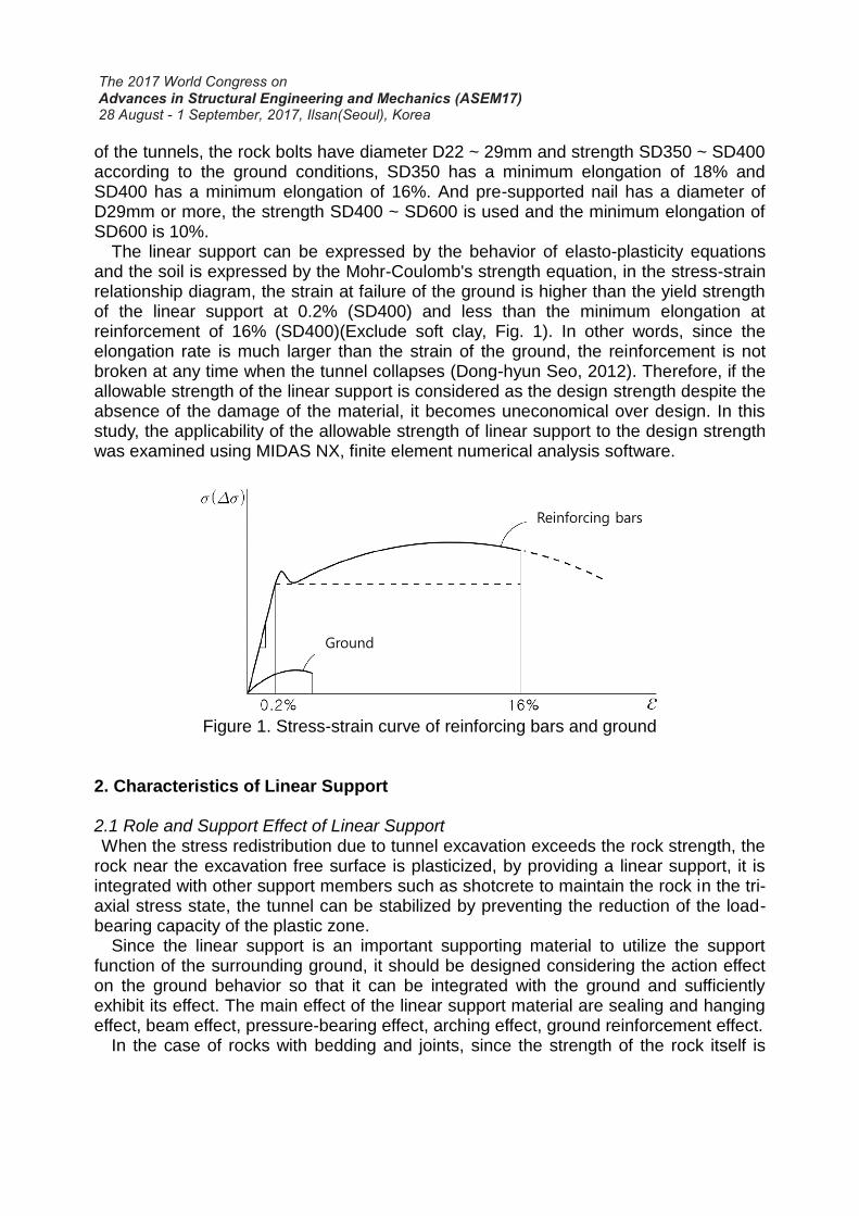
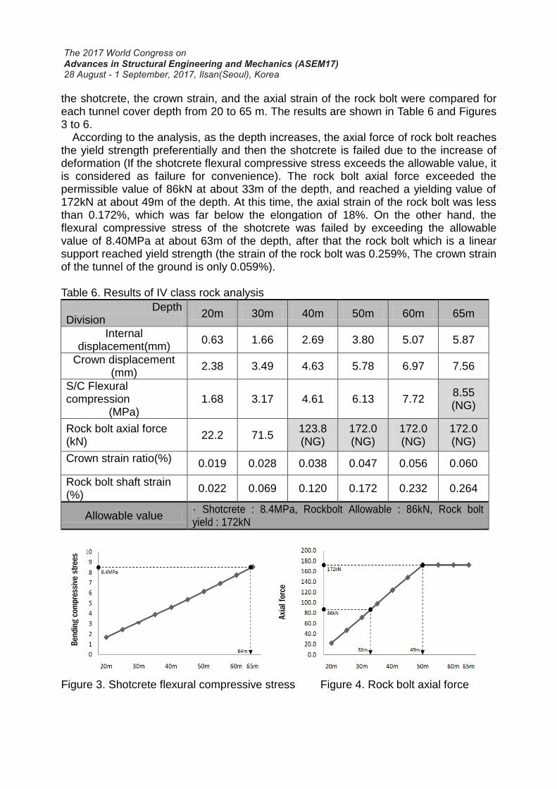
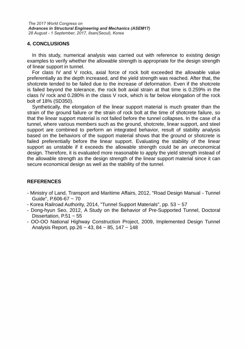
the shotcrete, the crown strain, and the axial strain of the rock bolt were compared for each tunnel cover depth from 20 to 65 m. The results are shown in Table 6 and Figures 3 to 6.
According to the analysis, as the depth increases, the axial force of rock bolt reaches the yield strength preferentially and then the shotcrete is failed due to the increase of deformation (If the shotcrete flexural compressive stress exceeds the allowable value, it is considered as failure for convenience). The rock bolt axial force exceeded the permissible value of 86kN at about 33m of the depth, and reached a yielding value of 172kN at about 49m of the depth. At this time, the axial strain of the rock bolt was less than 0.172%, which was far below the elongation of 18%. On the other hand, the flexural compressive stress of the shotcrete was failed by exceeding the allowable value of 8.40MPa at about 63m of the depth, after that the rock bolt which is a linear support reached yield strength (the strain of the rock bolt was 0.259%, The crown strain of the tunnel of the ground is only 0.059%). Table 6. Results of IV class rock analysis
Figure 5. Crown displacement Figure 6. Rock bolt shaft strain
If the stability of the tunnel is evaluated based on the allowable strength of the rock
bolts according to the present design standards, it is impossible to secure the tunnel stability under the condition of the depth of about 33m or more. However, considering the elongation of the rock bolts, if there is sufficient margin for the strain until failure, it is possible to secure the stability of the tunnel in a section of cover depth is less than about 63m where the stress of shotcrete is less than the allowable value. As the rock bolt has a large elongation, shotcrete will breakdown preferentially compare to rock bolt.
3.5.1 Results of Class V rock mass analysis
For class V rocks, the axial force of the rock bolt, the flexural compression stress of the shotcrete, crown displacement and the axial strain of the rock bolt were compared and compared for each tunnel cover depth from 10 to 45m. The results are shown in Table. 7 and Figures 7 to 10. Table 7. Results of V class rock mass
Allowable value · Shotcrete : 8.4MPa, Rockbolt Allowable : 86kN, Rock bolt yield : 172kN
According to the analysis results, as the depth increases, axial force of rock bolt first
reaches the yield strength and then the shotcrete is failed due to the increase of deformation. The rock bolt axial force exceeded the permissible value of 86kN at about
11m of the depth, and reached a yielding value of 172kN at about 21m of the depth. At this time, the axial strain of the rock bolt was less than 0.238%, which was far below the elongation of 18%. On the other hand, the flexural compressive stress of the shotcrete was failed by exceeding the allowable value of 8.40MPa at about 27m of the depth, after that the rock bolt which is a linear support reached the yield strength (the strain of the rock bolt was 0.28%, The crown strain of the tunnel is only 0.092%).
Figure 7. Shotcrete flexural compressive stress Figure 8. Rock bolt axial force
Figure 9. Crown displacement Figure 10. Rock bolt shaft strain
If the stability of the tunnel is evaluated based on the allowable strength of the rock
bolts according to the present design standards, it is impossible to secure the tunnel stability under the condition of the depth of about 11m or more. However, considering the elongation of the rock bolts, if there is sufficient margin for the strain until failure, it is possible to secure the stability of the tunnel in a section of cover depth is less than about 27m where the stress of shotcrete is less than the allowable value. As the rock bolt has a large elongation, shotcrete will breakdown preferentially compare to rock bolt.
In this study, numerical analysis was carried out with reference to existing design examples to verify whether the allowable strength is appropriate for the design strength of linear support in tunnel.
For class IV and V rocks, axial force of rock bolt exceeded the allowable value preferentially as the depth increased, and the yield strength was reached. After that, the shotcrete tended to be failed due to the increase of deformation. Even if the shotcrete is failed beyond the tolerance, the rock bolt axial strain at that time is 0.259% in the class IV rock and 0.280% in the class V rock, which is far below elongation of the rock bolt of 18% (SD350).
Synthetically, the elongation of the linear support material is much greater than the strain of the ground failure or the strain of rock bolt at the time of shotcrete failure, so that the linear support material is not failed before the tunnel collapses. In the case of a tunnel, where various members such as the ground, shotcrete, linear support, and steel support are combined to perform an integrated behavior, result of stability analysis based on the behaviors of the support material shows that the ground or shotcrete is failed preferentially before the linear support. Evaluating the stability of the linear support as unstable if it exceeds the allowable strength could be an uneconomical design. Therefore, it is evaluated more reasonable to apply the yield strength instead of the allowable strength as the design strength of the linear support material since it can secure economical design as well as the stability of the tunnel. REFERENCES - Ministry of Land, Transport and Maritime Affairs, 2012, "Road Design Manual - Tunnel
Guide", P.606-67 ~ 70 - Korea Railroad Authority, 2014, "Tunnel Support Materials", pp. 53 ~ 57 - Dong-hyun Seo, 2012, A Study on the Behavior of Pre-Supported Tunnel, Doctoral
Dissertation, P.51 ~ 55 - OO-OO National Highway Construction Project, 2009, Implemented Design Tunnel