1. Introduction Automation with cam mechanisms, although they offer a low degree of flexibility, are frequently used due to their low cost and to the fact that they provide the simplest way of achieving almost any desired follower motion. It has been widely or generally used the three-axis CNC machining center for the manufacturing of disk cams. For the case of manufacturing of combined disk cams (three or more disk cams) with single cam shaft, however it is not possible or difficult to manufacture such cams using the traditional three-axis CNC machining center. A five-axis CNC machining center is presently one of the most versatile machine tools available for such disk cams and they are becoming increasingly common. To increase the accuracy capabilities of such a machine, it is crucial to be able to study the geometric errors of the components and its effect on the quality of machined products. It should be noted that the paper does not focus on the geometric error of the structural elements of the milling machine, such as positioning errors of the machine axes, spindle errors, thermally induced geometric errors, etc. We will confine ourselves to the influence of the specific geometric-kinematic factor, namely the particular tool path that guides the cutting tool. In other words, we investigate the extent to which the machining tool path evaluated by the CAD/CAM computer contributes to the inaccuracy of a machined disk cam. To improve part quality with minimal machining time (i.e. to create the well-compensated NC code) for the disk cams in a five-axis CNC machining center, the control of tool path calculation with minimal error and its communication to the NC unit are imperative. Generally, the tool motion functions can be described utilizing linear, circular, polynomial or spline interpolation algorithms. The application of linear interpolation algorithms (first-degree functions), leads to follower velocity and acceleration discontinuities, which cause vibrations, mainly in high-speed mechanisms. The use of second-degree functions, as a basis for circular interpolation algorithms, eliminates the follower velocity discontinuities and may lead to satisfactory results regarding the dynamic behavior of the cam mechanism. Using a circular interpolation algorithm a certain number of cam profile points, regarding minimum distances between them, is required. Small increments between successive points may lead to undercutting and the NC code size increases considerably. Furthermore, a successive change of the curvature of the circular arcs from convex to concave is caused and significant deviations of the real transfer functions (velocity, acceleration, etc.) from the corresponding calculated ones occur. Using higher-degree functions, such as interpolation equations, like polynomials or splines, continuous second and higher order cam transfer functions can be achieved. The applicable A Study on Tool Path Error Control for Disk Cams in a Five-Axis CNC Machining Center Soon-Man Kwon, Joong-Ho Shin and Geun-Jong Yoo Department of Mechanical Design and Manufacturing, Changwon National University, Changwon 641-773, South Korea Abstract: In this paper, we propose a simple but optimized NC code generating technique for disk cams by means of tool path error control in a five-axis CNC machining center. Using the geometric theorem of the triangle made between manufacturing points and error checkpoint, the tool path error has been studied for disk cams profile generation and an improvement in the profile has been obtained. Then, based on the present manufacturing approach a computer program is developed on C ++ language to perform and to verify the shape design, the manufacturing simulation, and the optimized generation of the NC code. Key Words: Tool Path Error, Disk Cam, five-Axis CNC Machining Center, NC Code ICCAS2004 August 25-27, The Shangri-La Hotel, Bangkok , THAILAND 1012
Transcript
1. Introduction
Automation with cam mechanisms, although theyoffer a low degree of flexibility, are frequentlyused due to their low cost and to the fact thatthey provide the simplest way of achievingalmost any desired follower motion. It has beenwidely or generally used the three-axis CNCmachining center for the manufacturing of diskcams. For the case of manufacturing of combineddisk cams (three or more disk cams) with singlecam shaft, however it is not possible or difficultto manufacture such cams using the traditionalthree-axis CNC machining center. A five-axisCNC machining center is presently one of themost versatile machine tools available for suchdisk cams and they are becoming increasinglycommon. To increase the accuracy capabilities ofsuch a machine, it is crucial to be able to studythe geometric errors of the components and itseffect on the quality of machined products.It should be noted that the paper does not focuson the geometric error of the structural elementsof the milling machine, such as positioning errorsof the machine axes, spindle errors, thermallyinduced geometric errors, etc. We will confineourselves to the influence of the specificgeometric-kinematic factor, namely the particulartool path that guides the cutting tool. In otherwords, we investigate the extent to which themachining tool path evaluated by the CAD/CAMcomputer contributes to the inaccuracy of a
machined disk cam.To improve part quality with minimal machiningtime (i.e. to create the well-compensated NCcode) for the disk cams in a five-axis CNCmachining center, the control of tool pathcalculation with minimal error and itscommunication to the NC unit are imperative.Generally, the tool motion functions can bedescribed utilizing linear, circular, polynomial orspline interpolation algorithms. The application oflinear interpolation algorithms (first-degreefunctions), leads to follower velocity andacceleration discontinuities, which causevibrations, mainly in high-speed mechanisms. Theuse of second-degree functions, as a basis forcircular interpolation algorithms, eliminates thefollower velocity discontinuities and may lead tosatisfactory results regarding the dynamicbehavior of the cam mechanism. Using a circularinterpolation algorithm a certain number of camprofile points, regarding minimum distancesbetween them, is required. Small incrementsbetween successive points may lead toundercutting and the NC code size increasesconsiderably. Furthermore, a successive change ofthe curvature of the circular arcs from convex toconcave is caused and significant deviations ofthe real transfer functions (velocity, acceleration,etc.) from the corresponding calculated onesoccur. Using higher-degree functions, such asinterpolation equations, like polynomials orsplines, continuous second and higher order camtransfer functions can be achieved. The applicable
A Study on Tool Path Error Control for Disk Cams in a Five-Axis
CNC Machining Center
Soon-Man Kwon, Joong-Ho Shin and Geun-Jong Yoo
Department of Mechanical Design and Manufacturing, Changwon National University,
Changwon 641-773, South Korea
Abstract: In this paper, we propose a simple but optimized NC code generating technique for disk
cams by means of tool path error control in a five-axis CNC machining center. Using the geometric
theorem of the triangle made between manufacturing points and error checkpoint, the tool path error has
been studied for disk cams profile generation and an improvement in the profile has been obtained.
Then, based on the present manufacturing approach a computer program is developed on C++
language
to perform and to verify the shape design, the manufacturing simulation, and the optimized generation of
the NC code.
Key Words: Tool Path Error, Disk Cam, five-Axis CNC Machining Center, NC Code
ICCAS2004 August 25-27, The Shangri-La Hotel, Bangkok , THAILAND
1012
spline degree depends on the interpolationfacilities of the NC machine. To determine thenumber of the cam interpolation regions, the camaccuracy and the permitted transfer functionsdeviations have to be considered.In the present paper, we propose a simple butoptimized NC code generating technique for diskcams by means of tool path error control in afive-axis CNC machining center. Using thegeometric theorem of the triangle made betweenmanufacturing points and error checkpoint, thetool path error has been studied for disk camsprofile generation and an improvement in theprofile has been obtained. Then, based on thepresent manufacturing approach a computerprogram is developed on C
++language to
perform and to verify the shape design, themanufacturing simulation, and the optimizedgeneration of the NC code.
2. The Manufacturing of Disk Cam
Mechanism
There are many kinds of cams with variousfollowers. The general methods for the shapedesign of the cam include graphic layout methodand analytic ones. In a way of the shape designof the cam, recently, Shin et al. [1-3] presentedan approach to the shape design of disk cambased on the relative velocity of a followerversus a cam and the shape of the followerusing the velocity graphics, and to determinationof the curvature radius of disk cams usingacceleration graphics. Following the above-mentioned researches [1-3], the entire shape ofdisk cams can be determined via coordinatetransformation as follows (see Ref. [4] for moredetails)
(1)
where is an angle of cam rotation. Also
and represent contact points on the shape
design-coordinate, given by:
(Case 1) Translating roller follower:
(2)
(Case 2) Translating flat-faced follower:
(3)
(Case 3) Oscillating roller follower:
(4)
(Case 4) Oscillating flat-faced follower:
(5)
where the notations in Eqs. (2)-(5) can be found
in Fig. 1.
(Case 1) (Case 2)
(Case 3) (Case 4)
Fig. 1 Various types of disk cam
A 5-axes machine tool has the ability ofsimultaneously positioning and orienting thecutting tool in some coordinate system defined inthe work space. This makes such a machine toolvery versatile. The configuration of the 5-axesCNC machining center can be assembled inseveral ways. In this study, horizontal 5-axesmachining center is used, which consist of theusual three translation motion axes (Z2, Z3, Z4)and two rotation axes (Z0, Z1), as shown in Fig.2.
fX
fZ
fY
frame
2
1
3
45
0
2Z
2X
1X
1Z
3Z
3X
4Z
54,X X
0Z0X
5Z
Fig. 2 A 5-axes CNC machine centerconfiguration set-up
From the shape design data, the tool location ofrough and finishing manufacturing with generaltools is defined in Fig. 3.The cutter location is calculated from the shapedata of the disk cam, given by:
(6)
1013
(7)
(8)
where { } represent contact points of Eqs.(2)-(5) in the shape-design-coordinate, =i×TD(i=1,2,3 n) and TD is a tool diameter.
Fig. 3 Cutter location with respect to contactpoint of the disk cam
To extract NC-code data in a 5-axes machiningcenter, the tool path position and orientation willbe defined via coordinate mapping technique. Inperforming a manufacturing, it is necessary tocoincide the machining point with design-coordinate Xd. It is possible to perform arotational transformation between tool-coordinatet(Xt, Yt) and design-coordinate d(Xd, Yd). Also,to obtain the translation motion data, we mapwork-coordinate f into shape-design-coordinate d(see Figs. 4 and 5).
fX
fZ
fY
frame
2
1
3
45
0
2Z
2X
1X
1Z
3Z
54,X X
0Z0X
5Z
Fig. 4 Coordinate systems of workpieceon a 5-axes CNC machining center
After such a consideration, we lead to thefollowing NC-code generation equation
(9)where
(10a)
(10b)
Therefore, the NC-code for the above four types
of the disk cam can be expressed as
(11)
where is the rotation angle of the tool whichis dependent of the cam type, and here is theinterference corrected angle to avoid toolinterference under the consideration of thenegative curvature.
frame
2
1
3
4
50
2Z
1X
1Z
3Z
3X
4Z
54,X X
0Z
5Z
fX
fZ
fY
Fig. 5 Coordinate systems of spindleon a 5-axes CNC machining center
3. Tool Path Error Controlby Biarc Algorithm
In programming the tool path of CNC machinery,fewer arc segments can help to improve theproduction efficiency by reducing the number ofinstructions and tool motions. In particular, thequality of cam depends upon the machine toolerrors. A biarc [5] can be described as twoconnected circular arcs with an identical tangentat the connecting point. At the connecting point,C
1tangent continuity is maintained. Furthermore
C2
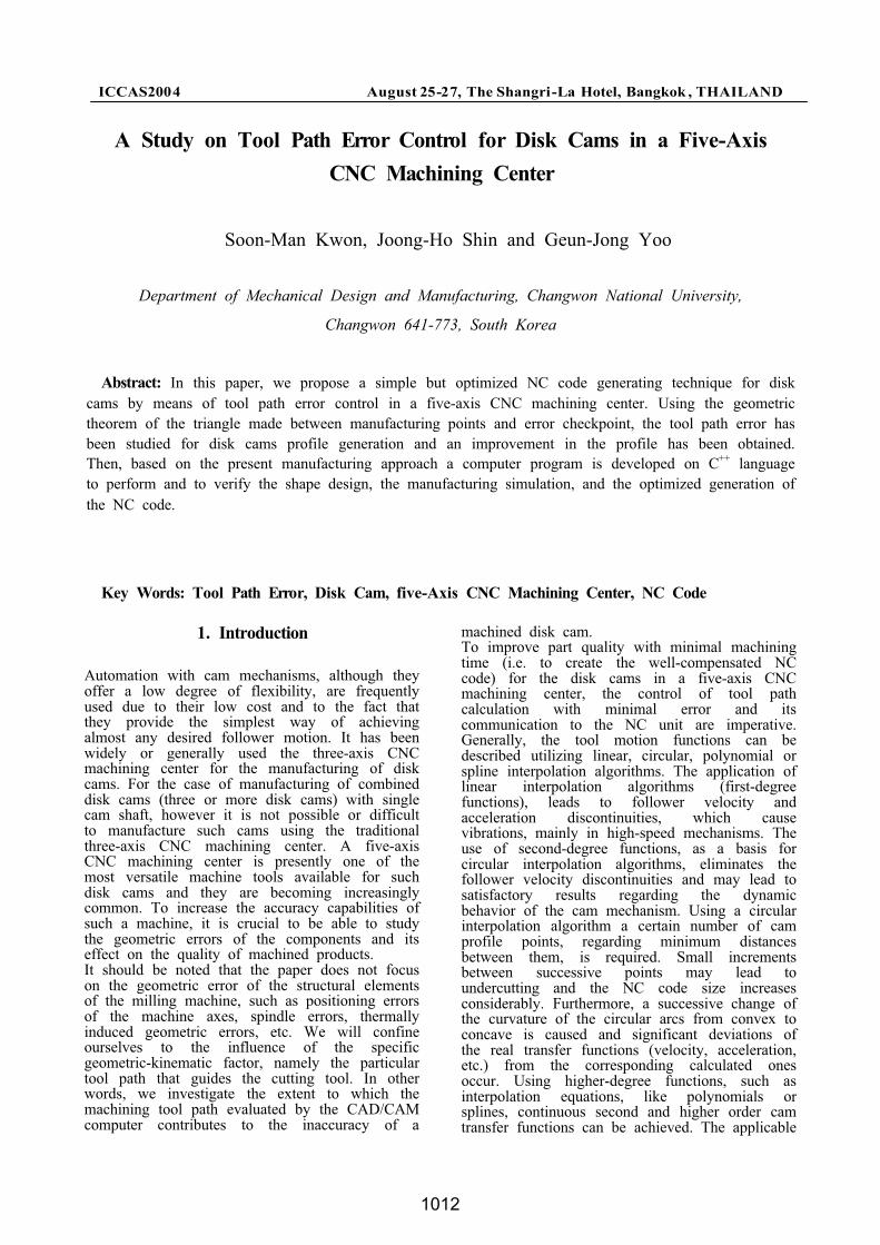
curvature continuity can be improved if thedifference between two curvatures at theconnecting point is minimized. The toleranceconstraint can be specified as the largestdeviation distance between the curve and theapproximating biarcs. From the machining pointof view, circular interpolation is the basicfunction in most NC machines. Therefore, biarcsare suitable for tool-path generation and NC codegeneration.A circular arc can be defined by a center, a startpoint, and an end point. Two circular arcs canbe linked if the end-point of the first arc andthe start point of the second arc are connected.If the tangents of the two circular arcs are thesame at the connecting point, then two circulararcs composes a biarc.In the present study, we adopted the biarcalgorithm by proposed by Bolton [5]. In Fig. 6,a biarc composed of two circular arcs isillustrated.
1014
Fig. 6 A biarc matching G1
Hermite data
As shown in the figure, using the geometrictheorem of the triangle the following equationcan be made
(12)
where is the chord length, and
(i=1,2) denote and ,
respectively. Also the sign ± in the last term ofleft hand side of equation means the unimodal(C-shape) and inflection (S-shape) biarcs,respectively.If we set R1, the radius R2 can be evaluated asfollows
(13)
Using Eq. (13), tool path error can be controlledby standard permitted tool path error. Figure 7shows tool path error defined by vertical distancebetween real tool path and linear tool path.
Pi
Pj Pi+1
Pj+1
Pi+2
Tool Path
Tool PathLinear Tool Path
Tool Path Error Tool Path Error
Fig. 7 Definition of tool path error
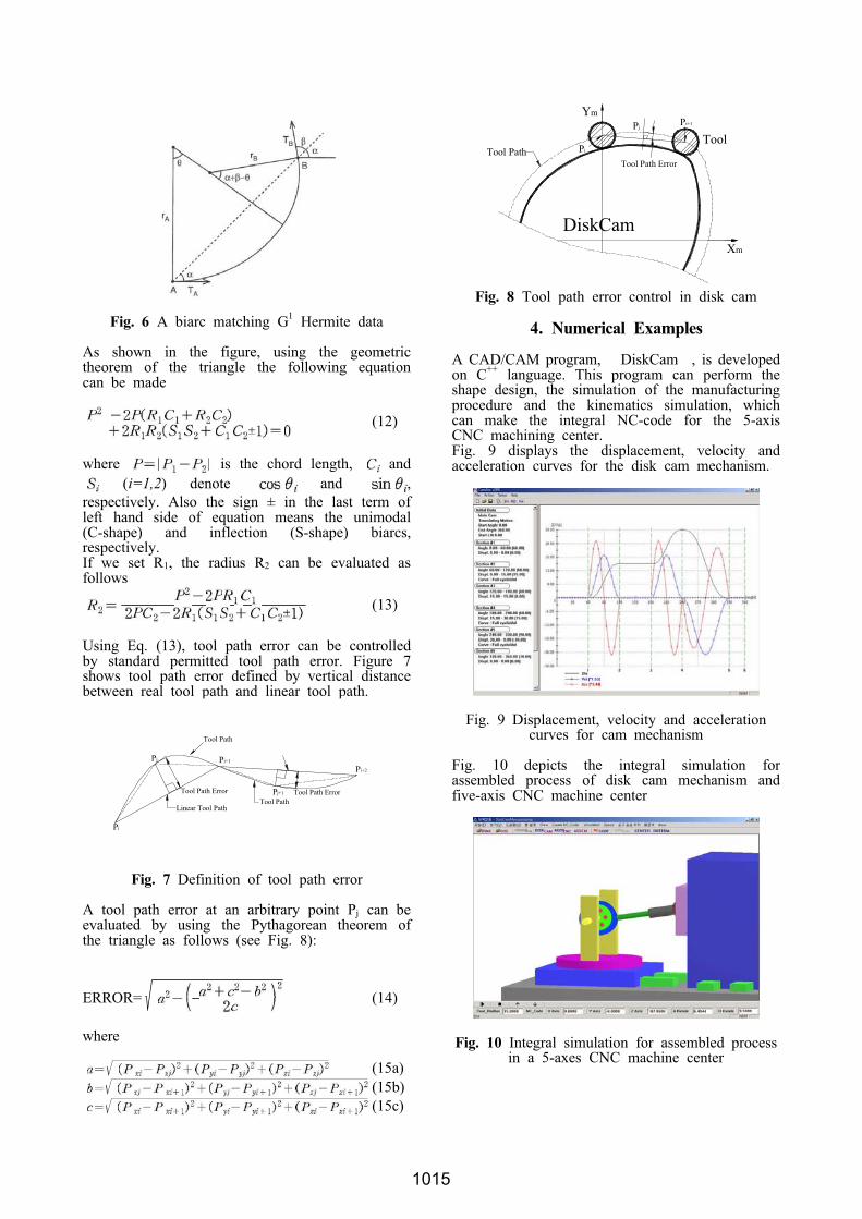
A tool path error at an arbitrary point Pj can beevaluated by using the Pythagorean theorem ofthe triangle as follows (see Fig. 8):
ERROR= (14)
where
(15a)
(15b)
(15c)
DiskCamXm
Ym
ToolPi
Pi+1Pj
Tool PathTool Path Error
Fig. 8 Tool path error control in disk cam
4. Numerical Examples
A CAD/CAM program, DiskCam , is developedon C
++language. This program can perform the
shape design, the simulation of the manufacturingprocedure and the kinematics simulation, whichcan make the integral NC-code for the 5-axisCNC machining center.Fig. 9 displays the displacement, velocity andacceleration curves for the disk cam mechanism.
Fig. 9 Displacement, velocity and accelerationcurves for cam mechanism
Fig. 10 depicts the integral simulation forassembled process of disk cam mechanism andfive-axis CNC machine center
Fig. 10 Integral simulation for assembled processin a 5-axes CNC machine center
1015
5. Conclusions
This paper proposes an approach for the shapedesign and manufacturing of the disk cam viatool path error control in a 5-axes CNC millingmachine. The following conclusions can bedrawn.
(1) The cutter location and cutter orientation aredefined for the manufacturing of the 5-axesmachining center from the shape data basedon the relative velocity method.
(2) The integral NC code for multi-axis CNCmachining center is proposed using thecoordinate transform method from the dataof location and orientation of cutter path ona horizontal 5-axes machining center whichis consist of three linear motion axes andtwo rotation axes.
(3) To improve the quality of the cam, the toolpath error is controlled by biarc algorithmand geometric theorem of the triangle.
(4) A CAD/CAM program, DiskCam , isdeveloped on C
++language. This program
can perform shape design, manufacturing andkinematics simulation, which can makeintegral NC code for multi-axis CNCmachining center.
References
[1] Shin, J.H., Kang, D.W., Kim, J.S. and Kim,D.W., 2000. A study on shape designapproach of disk cams using relative velocityof followers. J. of the Korean Society ofPrecision Engineering, 17 (2), 185-192.
[2] Shin, J.H., Kang, D.W., Kim, J.S. and Kim,D.W., 2000. A study on curvaturedetermination approach of disk cams usingrelative velocity of followers. J. of theKorean Society of Precision Engineering, 17(8), 113-119.
[3] Shin, J.H., Kang, D.W., Yoon, Y.H. andZhang, Y.H., 2001. An approach to shapedesign of disk cams using relative velocityof followers. Proceedigns of the InternationalSymposium on Mechanical Transmissions, 1,347-351.
[4] Kang, D.W., 2000. A study on designautomation technology of complexmechanisms with disk cams and cylindricalcams for multi-axis motion control. Ph.D.Thesis, Changwon National University,Korea.