A Survey of Analytical Tools for Explosion Investigation K. R.Mniszewski FX Engineenng,Inc., Hinsdale, Illinois, USA R. Pape Engineering Systems Inc., Aurora, Illinois, USA il,li r,l:. ,i:1" j ABSTRACT Practical analytical techniques that have been found to be useful in explosion investiga- tion include: timeline analysis, experimental dato comparisons, thermochemical code analy- sis, TNT and other air blast equivalency tech- niques, ground shock analysis, dynamic gas concentration estimates, simple fuellair explo- sion codes,damagepattern analysis and sys- tem saJbty analysismethods.An example appti- cation of existinganalytical tools to an explo- sion investigation is presented. Exotic analyti- cal techniques are available but are not justi- fied unlessthe lossis very large. Method"ology is reviewedfor completing a reasonable explo- sion investigation, including essential items from NFPA 921. Needs are addressed for de- sired t ec hnolo gy advanc eme nts. Keywords: explosion investigation, thermo- chemical equilibrium, blast equivalency, system safety analysis, ground shock Introduction The investigation of explosions can be an extremely complex task depending on the na- ture of the incident. Evidence is often de- stroyed by the forces involved or subsequent fires. The evidence may be spreadout ou", tut extremely large area. Fuels and oxidizers in- volved may or may nor be easily identified. Pyrotechnic and explosive materials involved will generally be consumed in the event, and the materials that remain after and incident may be misleading. Fuel gases involved in a fuel-air explosion are often dissipatedbefore any investigators are on the scene. The explo- sion origin can be difficult to pinpointdue to a lack of explosion seating (e.g., the absence of a crater).Propagation patternsmay be lacking or conflictingin some cases. Ignitionsources may be extremely difficult to identify, due ro prob- lems in establishing the origin, or perhaps in sorting out the source from a plethoraof viable sources. A basic knowledge of the chemistry and physics of explosions is necessary for an intel- ligent evaluation of an accident scene. Several specialized experts might necessarily be in- volved depending on the kind of answers that are desired. Typical questions that need an- swersare: . Wherewas the origin of the explosion? . What material exploded? . How much material exploded? . How was it initiated? . What was the extent of damage/injury? . How can it be prevented from recurring? The bestpathwayto answering these ques- tions is the scientific method. This paper is an overview of analytical tools that have proven to be useful in facilitating rhe scienrific method in explosion investigations. Page 16 Journal of Pyrotechnics, Issue 12, Winter 2fi)0
Transcript
A Survey of Analytical Tools forExplosion Investigation
K. R. MniszewskiFX Engineenng,Inc., Hinsdale, Illinois, USA
R. PapeEngineering Systems Inc., Aurora, Illinois, USA
il,li
r,l:.
,i:1"
j
ABSTRACT
Practical analytical techniques that havebeen found to be useful in explosion investiga-tion include: timeline analysis, experimentaldato comparisons, thermochemical code analy-sis, TNT and other air blast equivalency tech-niques, ground shock analysis, dynamic gasconcentration estimates, simple fuellair explo-sion codes, damage pattern analysis and sys-tem saJbty analysis methods. An example appti-cation of existing analytical tools to an explo-sion investigation is presented. Exotic analyti-cal techniques are available but are not justi-fied unless the loss is very large. Method"ologyis reviewedfor completing a reasonable explo-sion investigation, including essential itemsfrom NFPA 921. Needs are addressed for de-sired t ec hnolo gy advanc eme nt s.
The investigation of explosions can be anextremely complex task depending on the na-ture of the incident. Evidence is often de-stroyed by the forces involved or subsequentfires. The evidence may be spread out ou", tutextremely large area. Fuels and oxidizers in-volved may or may nor be easily identified.Pyrotechnic and explosive materials involvedwill generally be consumed in the event, andthe materials that remain after and incidentmay be misleading. Fuel gases involved in a
fuel-air explosion are often dissipated beforeany investigators are on the scene. The explo-sion origin can be difficult to pinpoint due to alack of explosion seating (e.g., the absence of acrater). Propagation patterns may be lacking orconflicting in some cases. Ignition sources maybe extremely difficult to identify, due ro prob-lems in establishing the origin, or perhaps insorting out the source from a plethora of viablesources.
A basic knowledge of the chemistry andphysics of explosions is necessary for an intel-ligent evaluation of an accident scene. Severalspecialized experts might necessarily be in-volved depending on the kind of answers thatare desired. Typical questions that need an-swers are:
. Where was the origin of the explosion?
. What material exploded?
. How much material exploded?
. How was it initiated?
. What was the extent of damage/injury?
. How can it be prevented from recurring?
The best pathway to answering these ques-tions is the scientific method. This paper is anoverview of analytical tools that have provento be useful in facilitating rhe scienrific methodin explosion invest igat ions.
Page 16 Journal of Pyrotechnics, Issue 12, Winter 2fi)0
Conducting the ExplosionInvestigation
An explosion investigation and analysis is acomplex endeavor that needs to be approachedin a systematic manner using the scientificmethod. The initial steps will include securingthe scene to prevent spoliation of evidence,assessment and documentation of the scene,and collection and preservation of evidence.This will be combined with other relevant datacollection and interviews of witnesses. Thedata is then inductively analyzed and a hypoth-esis developed. The hypothesis is then deduc-tively tested by comparing it to all knownfacts. If the hypothesis is inconsistent with theknown facts, it should be discarded and an-other hypothesis examined. This may identifythe need to collect additional data or performother analyses.
Of course, the extent of an investigator'sinvolvement may vary with his assignment andmay only cover part of the overall investiga-tion. In some cases an investigator's involve-ment may evcn occur several years after theincident.
Additional details of the investigation meth-odof ogy are given in Chapters 2 and 13 ofNFPA 921. Guide lbr Fire and Explosion In-vestigation.t'l The analytical tools described inthis paper can be used to assist in both the de-velopment and testing of hypotheses, which isthe essential element of the scientific methodin explosion invest igat ion.
Journal of Pyrotechnlcs. Issue 12. Winter 20O0 Page 17
Useful Analytical Tools
There are a wide variety of analytical toolsfor possible use in explosion investigation.These may range from simple fluid dynamicexpressions for estimating leak rates, to com-plex threedimensional computational fluid dy-namic models for estimating explosive reactionpropagation through a structure. Quite oftendesign-basis tools are too conservative for usein evaluating explosions. That is because engi-neering design-basis tools are usually standard-ized to assume idealized phenomena and in-corporate large safety factors to insure publicsafety. Although the typical accidental explo-sion is far from ideal, some design-basis explo-sion mitigation guides can be utilized in a re-verse-engineering fashion to be useful to theinvestigator. Other tools borrowed from fireinvestigation techniques and systems safetyscience are extremely valuable.
Analytical tools that have proven especiallyuseful in practice are listed below. Many ofthese tools may be incorporated in future edi-tions of NFPA 921.
Timeline Analysis
A timeline is a graphical or narrative repre-sentation of the events related to the incidentthat are arranged in some chronological order.The events included in the timeline may occurbefore, during or after the incident. This valu-able investigative tool can show relationshipsbetween events, identify gaps or inconsisten-cies in information and sources, assist in wit-ness interviews, and otherwise assist in theanalysis and investigation of the incident.
The value of the timeline is dependent onthe accuracy of the information used to de-velop it and the interpretations of the personassembling it. One example of a complex time-line diagram is shown in Figure I from refer-ence 2.
Early Fire Spread in Batch Dryer and Process Building
Early lgnition Sequence
1 1 : 3 3 A M1 1 : 1 5 a m - 1 1 : 3 0 A M
Figure Ia. Pepconfire spread diagram.
1 1 : 4 0 A M
Drum or dryerto critical temDeralure
Jet t laming of drum 1:Flaming particlesproJect upwards andthrough wall pan€lopening
Flaming particless€ttle and ignrte opendrum 2 (NE corner):Smoke sighted aboveprocess building
Page l8 Journal of Pvrotechnic's, Issue 12, Winter 2000
Fire Spread throughout Remainder of Plant
Figure Ib. Pepconfire spread diagram (continued).
alongvafles
Area 7 SSD rowsof poly drums
Poly drum rowsin areas 8, 9, 10
Burning partrclesraining down inprocess building
Fire spread tosections of plantby burning drumprojectiles
Explosion occursin poly drum orbatch dryer
N to empty polydrums in frontof adm. bldg.
To middle ol lot Ain poly drum and
Fire spreadthrough bulkstorage is about3.5 fVsec
Anode bui ldingFlame heightduring main NElire spread alonpoly drums varifrom about 100to 270 ft tall
11:53 :32
o-lSW corner of lot A L]Fireballs in lot Aand poty drumrolrvs coalesce toform a single 270 flhioh fir€ball
Chlorate bui lding
Malor Exploslons
1 1 : 5 3 A M 1 1 : 5 3 : 0 1 . 1 1 1 1 : 5 3 : 0 1 . 4 0Large fare plumessuppressed due loupheaval (radiationattenuated)
First majorexplosion(lot A)
Explosion incrystallizer/dryerbui lding
Explosion inchloratebui lding
1 1 : 5 5 - 1 1 : 5 7
Several small explosions
Exolosion near coordinate
1 1 : 5 7 A M1 1 : 5 7 : ' 1 5 A M
Second majorexplosion (lot B)
Ground f lash nearcoordinales 354/65-840.03 seconds earlier
354/85 at .1 1:55:23.81
Bin explosion on loadingdock a t 11 :55 :31 .71
Gas pipe rupturefire appareni
Bin explosion on loadingdock at 11:55:36.87
Journal of Pvrotechnics, Issue 12, Winter 2000 Page 19
t{itii'.riffii*lrmi'4$fiF.l.ffiJs!
.fllidi'ttil
filfl
:(:1.
hperimental Data Comparisons
Useful experimental data for explosioninvestigation covers a broad range of topics.These can include data on minimum ignitionenergy of dust clouds, maximum explosionpressure of a mixture of gases, maximum ex-plosion pressure under specified vented condi-tions, explosion limits of fuel gases, critical di-ameters of solid explosives, explosion air blastor TNT equivalency, etc. Each investigation isunique and requires data sources unique to therelevant issues. Sources of such data are muchtoo numerous to list here. but some useful tabu-lations are found in references l, and 3-7.
An important point regarding the use of suchdata sources is that much of the tabulated datais derived from standard tests, and cautionshould be exercised in their use. These datasources are usually developed to result in con-servative values so that their use will always erron the side of safety. Often times these data donot adequately fit the accident scenario of inter-est.
For example, the high and low strength en-closure venting data models in NFPA 68{31 aretoo conservative for many cases where less thanthe worst-case scenario is evident. Thus, it isusually quite difficult to use NFPA 68 ventingguides to help in the analysis of an accidentalbuilding explosion. This is because the strengthof the structure arrd explosion vent parametersis often unknown. In addition, information onthe fuel-gas mixture content and concentrationgenerally are lacking.
The use of ASTM E 12261'!t test data involv-ing maximum pressure development for dusts isanother example where the source data do notadequately fit the scenario. The standard testrequires sieving the dust sample to 200 mesh.This gives conservative results in most cases,even though the fines are more easily loftedthan coarse particles, they generally dominatethe explosion effects. Due to the sieving, thetest does not consider the agglomeration of par-ticles with, for example, wood dusts in high hu-midity or plastic dusts in low humidity (due toelectrostatic forces).
Fuel/Air Explosion Models
There are simplified methodologies for pre-dicting maximum pressure development in avented enclosure as well as flame speed andshape. However, these quasi-empirical methodsrequire input such as burning velocity, turbu-lence factors, enclosure geometry, and physicalvent parameters. Some of these methods aresummarized in reference 9 or listed in NFPA6 g . l 3 l
It should be noted that the present state-of-the-art in explosion science does not allow oneto reliably predict diffuse fuel explosion pres-sure development within an enclosure, usingany methodology. Computational Fluid Dynam-ics (CFD) is beginning to provide major im-provements in the analytical prediction of theeffects of volumetric explosions (i.e., gas, dustand hybrid explosive systems). A range of CFDcomputer codes exist, and many of these codesare commercially available, some examples arethe commercial FLUENT code, the KIVAcodel "'l and the IIT code.llr' '21 These codesclearly demonstrate that CFD technology isvery close to providing a valuable tool for ex-plosion investigation, but ar least three prob-lems remain before this analysis tool can bepractical. First, to represent realistic configura-tions the geometry is generally complex. Insome cases two-dimensional analysis may besufficient, but many times three-dimensionalcomputations are appropriate. In addition, theanalysis probably requires a fine numerical gridin at least some locations, and as a consequencea full evaluation generally requires substantialcomputer running time. Often a simplified con-figuration is adequate and can go a long waytowiud making the analysis more practical.Second, for explosion analysis the numericalmethod must have the ability to resolve shockwaves. This requires special numerical schemessuch as Godunov, Van Leer, Flux CorrectedTransport (FCT), Total Variation Decreasing(TVD), and others.lt '-ttl Third, the reaction ki-netics must be represented realistically. Oneapproach, given in references ll and l2,usesthe reaction kinetics in Arrhenius form. Gener-ally major simplifications in the kineticsscheme are made in analyses of this type.
{i
n:i{
Page 20 Journal of Pyrotechnics, Issue 12, Winter 2000
The work presented in references I I and 12was in support of experimental detonation tubestudies of a wide variety of pyrotechnic formu-lations being evaluated for landmine neutraliza-tion and other applications for the Army. For-mulations evaluated included pafticulate explo-sives (e.g., TNT and RDX), particulate ammo-nium perchlorate (AP), atomized and flakedaluminum, and other constituents dispersed inair and nitrogen (e.g., reference 26). Althoughthe work was not directly in support of processaccident investigation, the results of both theanalytical and experimental investigations arepotentially useful in understanding explosroneffects from a dispersed pyrotechnic in a proc-ess accident.
Usually an analysis involving major effort,such as a detailed CFD model is only justifiedin cases of very large losses. Although the accu-racy might not be improved by such an zmalysis(e.g., overpressure prediction), the insight intothephysics involved might be greatly enhanced.For these reasons, there is stil l a strong relianceon measurements from large-scale experiments.Although large-scale experiments are costly,these experimental results are more easily ac-cepted than are predictions based upon analysis.
TNT Equivalency and Other EquivalencyMethods
TNT equivalency or other equivalency meth-ods are particularly useful for the analysis oflarge-scale accidents with high overpressures atthe origin (e.g., vapor cloud, condensed explo-sive, and some pyrotechnic material accidents).In TNT equivalency methods, the available ex-plosion energy in the accident is converted tothe equivalent mass of TNT. Thus, explosioneffects, particularly overpressure as a functionof distance, are then basically a function of theTNT equivalent mass. Explosion effects forTNT are well known and available in variousreferences (e.g., see references 5 and27-30).
The TNT equivalency approach is discussedin the context of chemical process explosions inPerry's Chemicctl Engineer' s Handbook.t:tl Py-rotechnics manufacturing operations are in factchemical process plants, with specialized as-pects due to the reactive nature of the finalproducts and many of the in-process material
forms. Of particular concem in the generalchemical process industry are chemical reactorrunaway reactions, inert pressure vessel explo-sions, and pressure vessel explosions involvingflash vaporizing liquids. For pressure vesselexplosions involving compressed gas, theequivalent mass of TNT is computed by assum-ing isentropic expansion of the gas from theinitial vessel pressure to ambient pressure anddividing by the detonation energy of TNT. Theresultant energy is partitioned into 30Vo forblast, 40Vo for fragments, and 30Vo for otherdissipative mechanisms. For diffuse fuels suchas flammable vapor clouds, a yield factor istypically applied to the calculation to accountfor inefficiencies in explosive combustion,mainly due to inhomogeneities in fuel-air mix-ing. This factor usually ranges from I to 40Vodepending on the circumstances. TNT equiva-lency methods are generally thought to be satis-factory as long as the far-field potential is themajor concem. In the near field, where therecan be significant distortion of the blast, theneither numerical modeling or simulation ex-periments must be conducted.
Other equivalency methods have evolved inrecent years for systems such as flammable va-por clouds. The multi-energy method has re-ceived wide acceptance for use with unconfinedvapor cloud explosions. In this method, poten-tial sources of strong blast are identified, ener-gies are computed, and the relative blaststrength is estimated. Strong blast sources gen-erally correspond to locations where there ispartial confinement or where the cloud is con-gested with obstacles that produce turbulence.Sachs-scaled blast parameters are utilized todetermine blast variables of interest as a func-tion of distance. Blast variables generally in-clude peak over-pressure, positive phase im-pulse, time of amval, positive phase duration,and shock velocity. A good compilation anddiscussion of these methods is listed in refer-ence 32.
Ground Shock Analysis
After an accidental explosion occurs, thereare generally numerous reports of damage tosurrounding property. This damage is manytimes attributed to air blast or ground shock. Fcr
Journal of Pyrotechnics, Issue 12, Winter 2000 Page 21
iif
,lij
air blast damage, the TNT equivalency methodsdescribed above can be used to evaluate whichof these claims are credible. An extension of theair blast methods can be employed to evaluateground shock damage, as well. Ground shockanalysis methods have been used for the designof structures to resist accidental explosions inpyrotechnics manufacturing and storage facili-ties, and to design structures to resist weaponseffects in military applications. Ground shockcan be evaluated as having two contributingparts: the air blast induced ground shock andthe direct induced ground shock. The ar blastinduced ground shock is (as the nzrne implies)the ground shock disturbance that follows theair shock as it propagates outward from theexplosion center. The direct induced groundshock is the disturbance that passes from theexplosion directly into the ground medium.This component depends on the coupling of theexplosion to the ground at the source. Manytimes the explosion is not in direct contact withthe ground surface, and the resulting direct in-duced ground shock is substantially diminishedbecause of this poor coupling. To conduct aground shock analysis, the characteristics of thesoil medium (e.g., seismic velocity and density)and characteristics of an underlayer such as thewater table or a rock layer must be known.
Sources of information on this subject canbe found in references 28-30. These are each ina workbook form, which aid in their appltcationby a knowledgeable practitioner. Each of thereferences were developed for different specificpurposes, and their domains of applicabilitymust be considered by the user. The PantexManualt28l concentrates on buried explosions,either in direct ground contact or within an un-derground cavity. Since the explosions are bur-ied, no air blast induced ground shock is con-sidered. TM 5-l300ttn1 is concerned with de-signing structures against accidental explosions.It considers both air blast induced ground shockand direct induced ground shock. These meth-ods do not directly include an underlayer. TM 5-855-1t301 is concemed with designing structuresagainst conventional weapons. To use this ap-proach for an above ground accidental explo-sion, an equivalent TNT hemisphere is assumedto sit on the ground surface. The height of theburst is not automatically taken into account for
ground shock. An underlayer can be consid-ered. These references provide the proceduresto conduct a good assessment of the effects ofground shock on structures, based on predictedmaximum displacement, velocity and accelera-tion. A criterion used frequently for the thresh-old of damage is a maximum velocity of 2inches (51mm) per second. A more compre-hensive approach is to conduct a structuralanalysis for a specific structure, given the pre-dicted ground shock characteristics.
Dynamic Fuel Concentration Modeling
The analysis of flammable gas concentra-tions has been used to evaluate whether a gasleak could have been responsible for afire/explosion incident and to assist indeterminrng the source of the gas. Thesemodels can be used to calculate the gasconcentration as related to time and elevation inthe space, and they can be correlated withexplosion damage. Models may range fromsimple exponential mixing calculations in acontrol volume, to detailed computational fluiddynamic (CFD) models incorporating diffusion,turbulence and gravity effects.
Flammable gas concentration modeling,combined with an evaluation of explosion/firedamage and the location of possible ignitionsources, can be used to establish whether or nota suspected or alleged lelk could have been thecause of an explosion/fire and to determinewhat source(s) of gas or fuel vapor was consis-tent with the explosion/fire scenario, damage,and possible ignition sources. Useful sources ofinformation on this topic include references 9,33, and 34.
Thermodynamic Chemical EquilibriumAnalysis
Fires and explosions that are suspected ofbeing caused by reactions of known or sus-pected chemical mixtures can be investigatedby a thermodynamic analysis of the probablechemical mixtures and potential contaminants.This type of analysis can be used ro help an-swer causal investigative questions such as:What reaction(s) could have caused thefire/explosion? Was the reaction spontaneous ordid it require an outside source of energy? Was
Page22 Journal of Ptrotechnics, Issue 12, Winter 2000
there an improper mixture of chemicals or acontamination? Did a chemical or chemicalmixture overheat? Was there a vapor releasefollowed by an outside ignition?
Thermodynamic reaction equilibrium analy-sis requires tedious hand calculations or the useof a complex computer code. Several of thesethermodynamic codes that are available are re-viewed in reference 35. These computer pro-grams usually require the input of material andthe material's properties that include the chemi-cal formula, density, mass, entropy and heat offormation. Sources for this information includethe JANAF tables,lr6l Chemical and ChemicalEngineering Handbooks, published papers, ma-terial safety data sheets, and the NIST Chemrs-try WebBook.trTl
The state of the art of equilibrium thermo-chemical codes for explosion analysis is repre-sented by the CHEETAH Code.lttl This codewas developed by Lawrence Livermore Labora-tory. It is an improved version of the TIGERCode.lrol The Code is quite easy ro use-i t isuser friendly. However, this code is currentlyavailable only to the govemment and govem-ment contractors working on government pro-jects. To use the code properly, the user shouldhave a reasonable understanding of how equi-librium thermochemical codes work. For exam-ple, there are several options for equation ofstate and species libraries, each of which hascertain domains of applicability. There are anumber of state characterizations to choosefrom. The primary application of this code isfor the characterization of condensed explosiveand pyrotechnic propellant formulations, butdiffuse fuel-air applications are easily handled.Because of the limited availability of this code,other codes such as NASA-Lewis and others(see reference 35) should be employed wherenecessary.
Damage Pattern Analysis
Damage pattem analysis usually includesanalysis of debris and structural damage. Often,it is very useful to prepare diagrams showingrelative damage pattems. Debris pattems oftencan show the direction and relative force of theexplosion. However, different drag or lift forcesof various fragment shapes will tend to favor
some shapes continuing on further trajectories.These factors must be considered in relativeforce comparisons. Quite often, investigatorserroneously assume that the fragments that havegone the furthest are representative of thestrongest force and direction of the explosion.References 27 and 32 aid in this type of analy-sis.
Structural damage analysis usually involvesthe estimation of overpressures and sometimesthe impulse necessary to produce the damage.Several generalized overpressure damage list-ings are compiled in the literature (see refer-ences 1 ,9 ,27 ,31 , and 32) . These are qu i te use-ful for making quick estimates. These lists areusually derived from data where explosive im-pulse is very high at a given overpressure,where the overpressure approximates a staticapplication. Thus, such data can be quite usefulfor applications involving fuel, gas or dust ex-plosions, where such an approximation is usu-al ly val id.
If needed, various structural computer pro-grams can be used, however, sometimes a struc-tural damage expert will be necessary. Someexamples of practical computer programs arelisted in reference 40.
Systems Safety Analysis
Systems Safety Analysis (SSA) techniquesare particularly useful for explosion investiga-tions. They can help identify potential causes ofan explosion, and they can indicate where fur-ther analysis should be directed. A formalizedSSA is generally most useful in a large and/orcomplex incident. It can be very effective inidentifying all factors, both physical and hu-man, which did or could have contributed to thecause of the explosion. Similarly, it can behelpful in eliminating potential causes of anexplosion.
These techniques include Failure Modes andEffects Analysis (FMEA), Fault Tree Analysis,HAZOP Analysis, What-If Analysis, etc. [ngeneral, these tools provide a systematicmethod for analyzing large complicated sys-tems to determine hazards or faults. The toolscan utilize either qualitative or quantitativeformats. Hazwd probabilities or failure ratescan be factored in when using quantitative for-
f ournul of P-rtrotechnics, Issue 12, Winter 2000 Page 23
$ffiffi
ffiffiffim
ffiffi;,"1
Fire or Explosion at Kernell ingMachine Due to Mechanical
Action
... Due to Bent orMisaligned
lmpeller
... Due to PartEntering from
Autoclave
... Due to Insufi icientlmpeller
Clearance
lmpellerBecomes
Misalignedor Bent
During theMaintenance
(scrapesvessel)
In Kernell ingMachine PartGets Caught
betweenWall andlmpeller
(Scrapes)
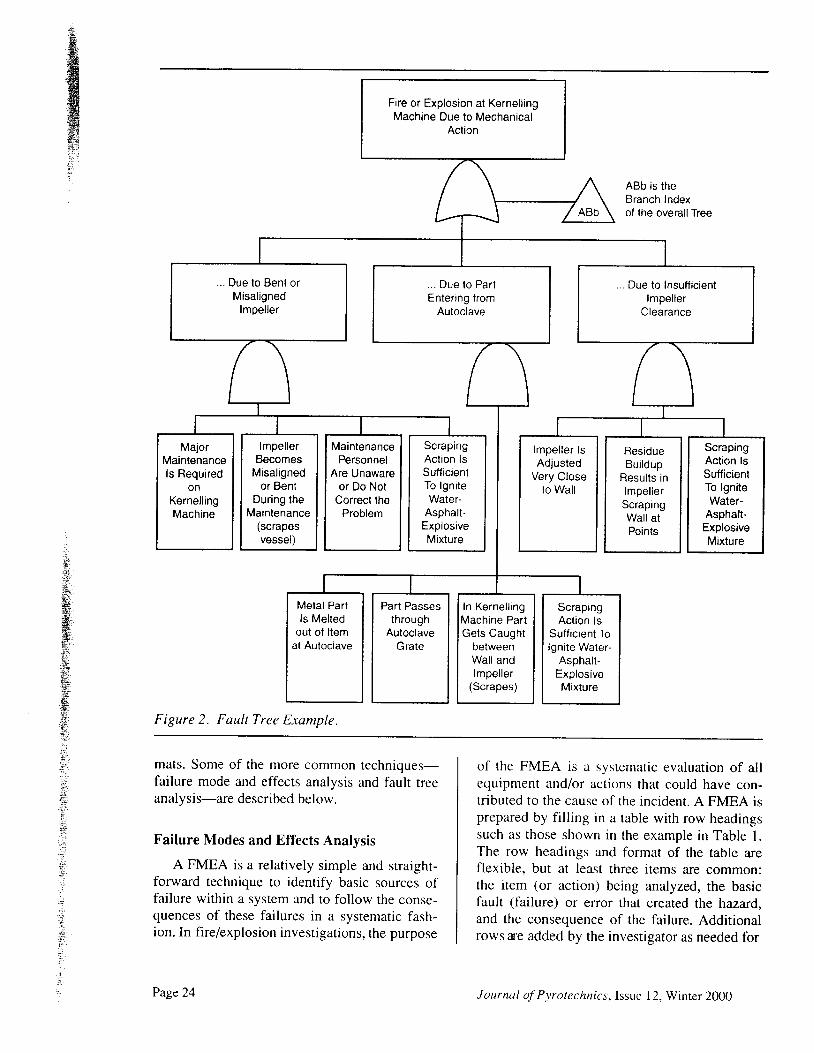
Figure 2. Fault Tree Example.
mats. Some of the more common techniques-failure mode and effects analysis and fault treeanalysis-are described below.
Failure Modes and Effects Analysis
A FMEA is a relatively simple and straight-forward technique to identify basic sources offailure within a system and to follow the conse-quences of these failures in a systematic fash-ion. In fire/explosion investigations, the purpose
of the FMEA is a systematic evaluation of allequipment and/or actions that could have con-tributed to the cause of the incident. A FMEA isprepared by filling in a table with row headingssuch as those shown in the example in Table l.The row headings and format of the table areflexible, but at least three items are common:the item (or action) being analyzed, the basicfault (failure) or error that created the hazard,and the consequence of the failure. Additionalrows tre added by the investigator as needed for
Page 24 Journal of Pvrotechnics, Issue 12, Winter 2000
aj
E(D
IY
9 o. = o 9
8 e h5 : . ;
" .a \ g - a
( 5 : ; 5
E c L^ , . ) € €x = 9 l :E € ; i E5 g E i €
at)
c
cq)EEoo(r
L -^L > : =( l ) o . Y l uo - > x -8 F g bc u c o fE 5 E S : X P5 3 g . F E H 8( / ) D @ J Dx : 7 ! - o h ( d 0x 7 i u > :" X - = L p E 6
i E 4."3= 5 BEsa a a a a
,o i> l
R E g RE ; b € , Ec ! = ; r c. F
H Y X i . F-
- * - : - ) tI E ' 9 E ; I E'F : . i tu ^;
'= := = , h E i = - 0 ,c H . o o r c F Io) j/ : ci o) v :l' i
D y f : ' ; ! ( / )
A g E S A 3 ;I
tl)
E
6 - t r E6 y *3 9 . o E: ( , o c )V L d L
c o = t r L: ! , ? o o l j* x i - : i $' - x ; Y =c ? i " ' ( D L
3 ; - 3 5
N -( ! ( g
I O
co
' -o(t(Do
dN(!
:E
q ) ( D
3 . q €- # , ^ -
: L d t
o o ) , : ; io Q s ;o ; Y ( o oo o ? hF r t s aF ' - L A
F g : €
OD COL 0 )
_ L
! q )
a ao a= 9 i ^o P q )O A U J
oc
( l ) ( Ux o* _.cc _' - ( d( t ) cq o
= ( J c )
c 5 : 3
o ( D C
3 - € - - b b5 . = o = q r ? i: - d f L L( D x : : ; i ' . = . =
v = L > n \ L
o 6 - 6 b { cS ( , q x l ' ;g E t s : 9 ;F E b E F €> H 5 c o - =i i E S e E B
(i>
uJ(D
:(g
LL
= u )' ;
: J /
E - oX ( )- l
A Y= w '
u O
i - -
=c
' 6
X OO ' O
o 9 -
E oo ' -
LL IIJ
; *3 oc ) Eo - ( o. - o -( D g( / ' OO - c
E F o= - u )o o o
; n a E-E HS E ; .,
; ; E g E g6 c E 9 i a c
s E 5 ; E st r . s b ; ; 3
o Yttl o-
] i-
=3
J
= o' f r od >
> \ _ _ L ( ,
9 o o o => L L 6 -L - J - d \
. Y o ; O >L ' ) O . : : . c O
.s9 s b -o _ e o - o> + A r6 r O ^ X
o)
( E c ) ( g
o x i ia 6 . 9 .
C 6 .
* a E g € €X : c = ( D i :w ( u ^
> 9 6 S 6 ' -
c
o !o - oo >
-6d C= Lt o
2 R
(d
( d Fb oo -
Z -<a
E(!zE
3 . R€ e EE : ' E H
- a_ >, (/)
s - o ou r > 7 i
; E 5tr; i o; z o
c.)NO(rJ
CAU)
(t)
I.q)
2,q)
9q)
X
ti
Page 25Journal of Pyrotechnic.r, Issue 12, Winter 2000
the particular investigation at hand. An assess-ment of the likelihood of each individual failuremode is frequently included. Also, it is some-times helpful to assess the severity of a givenfailure. Also, it is sometimes helpful to assess theseverity of a given failure relative to the fire/ex-plosion. FMEA tables can also be catalogued byitem and serve as reference material for furtherinvestigations.
When fil l ing out the table, the investigatorshould consider for each item/action the rangeof environmental conditions and the processstatus (i.e., normal operation, shutdown, startup,etc.). Qualitative or quantitative values can beassigned as probabilities of occurrence. Then,when a sequence of failures is required for anincident to occur, the probabilities can be com-bined to assess the likelihood that any giverrsequence ofevents led to the incident.
The usefulness of FMEA is limited by theability of the investigator to identify all systemcomponents (or human actions) that may havecontributed to the incident. Furthennore, theevaluation of the likelihood that a given se-quence of events caused the incident is only asgood as the ability of the investigator to assignaccurate probabilities to each of the individualfailure modes that contributed to the sequence.
Fault Tree AnalysisA fault tree is a diagram used to analyze an
undesired event. The undesired event is placedat the top of the diagram, and all the causes thatcan lead to the event are grouped below. Thisapproach is repeated for each cause and contin-ues until the desired level of detail is reached orthe root causes of the event are determined. Thediagram takes the form of an inverted tree. Therelationships between the events leading to theundesired event are described by the use of"AND" and "OR" gates at the junction(s) lead-ing to the next level of the event. An examplediagram is shown in Figure 2.
Once a complete fault-tree is developed foran undesired event, an investigator can look ateach of the root causes of the undesired eventand all of the steps necessary for the event tohappen. If any of the necessary steps did notoccur, the root cause associated with that par-ticular path can be eliminated.
It is possible to assign values associatedwith the probability of occurrence to the roorcauses and other independent aspects of thefault-tree. The probability of each path leadingto the undesired event can then be evaluated.The investigator will find that information onthe probability of the occurrence of causes isdifficult to find or not available. In most casesthe assignment of a probability of occurrencewill be based on experience, engineering judg-ment, tests, incident reports, models or pub-lished data. Any time probabilities are assumed,the sensitivity of the outcome to the assumedvalue should be determined by reevaluating theoutcome with slightly modified values.
Reference 4l provides additional guidelinesfor conducting these and other types of systemssaf-ety analyses.
Example Application
The use of some of these tools is il lustratedfor the Pepcon explosion investigation.t'i Thisincident originated as a fire in a large ammo-nium perchlorate (AP) plant located in Hender-son, Nevada. The fire quickly spread throughmost of the facility by means of thermal radia-tion, firebrands, a continuous (linear) source offuel, and some natural self-propelled missiles.Two large explosions occurred during the fire,each equivalent in energy to a few hundred tonsof TNT. The explosions claimed two lives, in-jured 372 people and damaged plant buildingsand nearby residential buildings. Some of thetools used in the analysis are illustrated below,in limited detail.
A videotape of the event from a nearbymountaintop permitted advanced reconstructivetechniques, such as superimposing CAD out-lines of the plant on video records. This, to-gether with witness accounrs, greatly aided inconstructing a detailed timeline of events fromignition, through various modes of flame spreadthrough the plant, to the two large explosions(see Figure l). The size and shape of the ex-tremely large fire plumes advancing through theplant were determined. Graphical plot plan dia-grams of the fire/explosion progress were pre-pared for different time slices (one example isshown in Figure 3).
Page 26 Journal of Pyrotechnics, Issue 12, Winter 2000
i i i { ^r l onTH I i \ /S' H I i \ l :
r I \ i 6l ! \ I covEREoPAHKr lG \ i ,Fr I covEREoPAHK[ lG \ / ,P ,
, , f . - t ; r I . . , \ , r !- . ' 1 I i , ai , ' . \ / :\ ,-t : ___..,/, \,__ _, V *.n
1/ eoer L_..- -f--- --r"_J \ _
ASS€MiJLY \ _
Figure 3. Pepcon Fire Progress at I l:52 AM
. . , . t - r r l rI t i I , I I | -
| - ; 1 i u r f [ l ^ . I I M E = - 1 1 . 5 2| , ' _ I - $ N S S N \ tWARE NOUSE _r OFFICE
Thermal radiation heat transfer calculatronsaided in the determination and confirmation ofthe flame-spread theories. A radiant heatingmodel was constructed that showed that signrfi-cant preheating of drums&ins of AP in storagelots near the huge fire plumes had occurred be-fore initiation of the detonation. The modelconsisted of a marching/growing radiant plumemodel coupled with a one-dimensional conduc-tion heat transfer model of a bin. Due to thelarge size of the bins and their onentation withrespect to the immense fire plumes, an assump-tion of modeling the bin as a semi-infinite solidwas appropriate. This analysis was very usefulin predicting that pyrolysis of AP rn stronglypreheated bins would cause them to burst anddisperse some of their contents onto nearby fu-els, providing a more-easily initiated explosionlayer, which could serve as an explostvebooster to the drums and bins.
Explosion dynamics estimates aided in de-termining the locations of the initial small ex-plosions and in estimating the amount of prod-
uct involved in the large explosions as sympa-thetic detonations. Experimental data on APand AP/fuel explosion chiuacteristics providedguidance for possible modes of explosion initia-tion and propagation. A thermodynamic equi-librium analysis was done to determine the en-ergy release from AP and different fuels at theplant. Structural damage data helped assess theoverpressures experienced in the area.
Possible causes of the initial fire were ascer-tained, and the most probable was related towelding sparks coming into contact with con-tamination-sensitized AP. The official causeremains undetermined. Conclusions were for-mulated regarding major factors involved in theignition, the extreme rate of fire spread, and theexplosion initiation and propagation.
Journal of Pyrotechnics, Issuc 12. Winter 2000 Page 21
Summary
Cunently the engineer investigator has arange of practical analytical tools for effectiveinvestigation of explosions. These "tools" canbe applied to the investigatron of incidents inpyrotechnics manufacturing facilities. Most ofthe tools require that accurate data from the in-cident be available. Thus, data gathering activi-ties are crucial to a successful investigation.
Although many analytical methods areavailable, desirable advancements in the area ofexplosion science to aid in such investigationsinclude: verified field modeling of vented ex-plosions in enclosures, a wider range of dataand models for estimating vented explosionexternal pressures, more refined models for gasmixing, additional experimental investigationand modeling for estimating cascade fuel/airexplosion overpressures in successive com-partments, and verified field modeling of explo-sions in highly elongated geometries.
References
NFPA 921, Guide for Fire und ExplosionI nvestigations, National Fire ProtectionAssociation ( 1998 ed.).
K. R. Mniszewski, "The Pepcon PlantFireiExplosion: A Rare Opportunity inFire/Explosion Investigation", J. FireProtection Engineering, Vol. 6, No. 2099q.
NFPA 68, Guide J'or Venting oJ'Deflagra-lions, National Fire Protection Association(1998 ed . ) .
R. K. Eckhoff , Dust Explosions in theP r oc e s s I ndus tr i e s, B utterworth-Heinmann( 1 9 9 1 ) .
CPIA, Hazards of Rocket Propellants,Vol. l-3, Chemical Propulsion Informa-tion Agency, CPIA Publication 394( l 985).
J. M. Kuchta,lnvestigation oJ'Fire andExplosion Accidents in the Chemical,Mining, and F ue l-Related I ndustrie s-AManual, Bureau of Mines, Bulletin 680( l 985).
l )
2)
3)
4)
s)
6)
Page 28 Journal of Pvrotechnics, Issue Winter 20O0
'7)
8 )
9 )
10)
l l )
t2)
1 3 )
t4)
l s )
l 6 )
Zalosh, R. G., "Explosion Protection"Chapter, Fire Protection Engineering,Society of Fire Protection Engineers, 2noed. (1995) .
ASTM E 1226-88, Stantlard Test Method
for Pressure and Rate of Pressure RiseforCombusrible Dusts ( I 988).
R. J. Harris, The Investigation and Controlof Gas Erplosions in Buildings and Heat-ing Planr, E&FN Spoon Ltd. (1983).
A. A. Amsden, J. D. Ramshaw, P. J.O'Rourke and J. K. Dukowicz, "KIVA:A Computer Program for Two- and Three-Dimensional Fluid Flows with ChemicalReactions and Fuel Sprays", Los AlamosNational Lab, NM, LA-10245-MS (1985).
R. Pape, D. Gidaspow and S. Wu, "Multi-phase Flow in Slurry Bubble Column Re-actors and Solid Propellant Rockets", Sec-ond International Svmposium on Numeri-cal Methods for Multiphase FLows, ASMEFluids Engineering Division, San Diego,CA (July t996).
R. Pape and D. Gidaspow, "NumericalSimulation of Intense Reaction Propaga-tion in Multiphase Systems", AIChE Jour-nal,Yol.44, No. 2 (February 1998).
G. C. Zha and F. Bilgen, "NumericalSolutions of Euler Equations by Using aNew Flux Vector Spl i t t ing Scheme", ln-ternational Journal for Numerical Meth-ods in Fluids, Vol. 17 (1993) pp 115-144.
B. Van Leer, "Towards the Ultimate Con-servation Difference Scheme V. A. Sec-ond-Order Sequel to Godunov's Method",Journal oJ'Computational Physics, Vol. 32(1979) pp 101-136.
S. K. Godunov, A. V. Zabrodin and G. P.Prokopov, "A Computational Scheme forTwo-Dimensional Non Stationary Prob-lems of Gas Dynamics and Calculation ofthe Flow From a Shock Wave Approach-ing a Stationery State", Zh. vych. mnt.,Vol. l , No. 6 (1961) pp 1020--1050.
B. A. Finlayson, Numerical Methods forProblems with Moving Fronts, RavennaPark Publishing, Inc., Seattle, WA (1992).
17)
1 8 )
l e )
20)
2t)
22)
z J )
) 4 \
2s)
M. R. Baer and R. J. Gross, "A Two-Dimensional Flux-Conected TransportSolver for Convectively DominatedFlows", Sandia Report SAND81-061 3,Reprinted (February I 989).
M. R. Book and M. A.Fry, "Airblast
Simulations Using Flux-Corrected Trans-port Codes", Naval Research LaboratoryMemorandum Report 5334, AD-A142 820(May 1984) .
D. L. Book. Ed.. "Flux Corrected Trans-porI", F inite - D iffere nc e T e c hniq ue s forVectorized F luid Dynamics Calculations,Chapter 3, Springer-Verlag, New York( l 9 8 l ) .
J. P. Boris and D. L. Book, "Flux-Corrected Transport III Minimal-EnorFCT Algorithms", Journal of Computa-tional Physics, Vol. 20 (1916) pp 397431.
R. J. Gross and M. R. Baer, "ETBFCT-ASolver fbr One-Dimensional TransportEquations", Sandia Report SAN D85 - I 27 3(October 198-5).
S. R. Chakravarthy, K. Y. Szema, U. C.Goldbert and J. J. Gorski, "Applications ofa New Class of High Accuracy TVDSchemes to the Navier-Stokes Equations",AIAA Paper 85-0165, American Instituteof Aeronautics and Astronautics , TwentyT hird Ae rospac e S c ie nc' e s M e e ti ng, Reno,NV (January l9U5).
S. R. Chakravarthy and S. Osher, "A NewClass of High Accuracy TVD Schemes forHyperbolic Conservation Laws", AIAAPaper [i5-0363, American Institute ofAeronautics and Astronautics, Twent vnT hird Aerospace Scie nc e s M eeting, Reno,NV (January 1985).
H. C. Yee, "Linearized Form of ImplicitTVD Schemes for the MultidrmensionalEuler and Navier-Stokes Equations",Computers & Mathematics u'ith Applica-r ions ,Yo l . l24 , No. 4 /5 (1985) pp 413-A a ^+ J Z .
H. C. Yee, "Construction of Explicit andImplicit Symmetric TVD Schemes andTheir Applications", Journal of Computa-t ional Physics, Vol. 68, No. 1 (1997).
26) A. J. Tulis et al., "PhenomenologicalAspects in Explosive Powder/Gas Two-Phase Detonations," Int. Symposium onC omhustion, Combustion Institute, Uni-versity of California, Irvine, CA ( l99a) p7 9 .
27) E. W Baker, et al., Explosion Hazards andEvaluation, Elsvier Publishing (l 983).
28) U.S. Department of Energy DOE/TIC-| 1268, A Manual for the Prediction ofBlast and Fragment Loading on Struc-tures, (Pantex Manual) (1980).
29) U.S. Army TM 5-1300, Structures to Re-sist the Effects oJ'Accidental Explosions( 1990) .
30) U.S. Army TM 5-855-l , Fundamentals ofP rote ct iv e D e si gn for C o nve ntionalW eapons (November I 986).
3l ) R. H. Perry and D.W. Green, Pernt'sChemical Engineer' s Handbook, McGrawH i l l ( l 9 9 9 ) .
32) AICHE, Guidelines for Evaluating theCharacteristics of Vapor Cloud Explo-sions, Flash Fires and BLEVEs, AICHE,Center for Chemical Process Safety, l " ed.(19e4).
33) R. H. Valentine, et al, "The TransientMixing of Propane in a Column of StableAir to Produce a Flammable butUndetected Mixture", W inter AnnualMeeting, American Society of MechanicalEngineers (November 1974).
34) V. A. Rabinkov, "The Distribution ofFlammable Gas Concentrations inRooms", Fire Safetl- Journal, Vol. 13,N o s . 2 & 3 ( M a y l 9 8 8 ) .
35) K R. Mniszewski, "The Use ofComputenzed Thermodynamic Tools inFire/Explosion Investigation", J. oJ FireProtection Engineering, Vol. 3, No. 3( l 9 9 l ) .
36) D. R. Stull and H. ProPhet, JANAFT he rm oc hemi c al Tab I e s, 2"" ed., Office of
Standard Reference Data, National Bureauof Standards, Washington, DC (1971).
37) NIST Chemistry WebBook, on the intemetat http://webbook.n ist.gov