NASA Technical Paper 3675 1997 National Aeronautics and Space Administration Ames Research Center A Survey of Theoretical and Experimental Coaxial Rotor Aerodynamic Research Colin P. Coleman, Ames Research Center, Moffett Field, California Moffett Field, California 94035-1000 https://ntrs.nasa.gov/search.jsp?R=19970015550 2018-06-21T13:17:02+00:00Z
Transcript
NASATechnical
Paper3675
1997
National Aeronautics and
Space Administration
Ames Research Center
A Survey of Theoretical and
Experimental Coaxial Rotor
Aerodynamic Research
Colin P. Coleman, Ames Research Center, Moffett Field, California
List of Figures ...........................................................................................................................................................
Research in the United States of America ................................................................................................................
NACA Langley Research Center ......................................................................................................................
De Lackner Helicopters, Inc ..............................................................................................................................
Research in Russia ....................................................................................................................................................
Research in Japan ......................................................................................................................................................
Research in the United Kingdom ..............................................................................................................................
Research in Germany ................................................................................................................................................
6 Schematic of the advancing blade concept (ref. 7) ..........................................................................................
7 Comparison of theoretical and experimental static-thrust performance of model ABC rotor,
H/D not reported (ref. 7) ..................................................................................................................................
8 Effect of rotor separation on ABC performance prediction (ref. 8) ................................................................
9 Underestimation of ABC rotor inflow at low speed (ref. 11) ..........................................................................
10 Flight test rotor of merit for XH-59A in OGE hover (ref. 13) ........................................................................
11 Induced power correction coefficient vs. blade linear twist for various taper ratio values (ref. 26) ...............
12 Coefficients kT and kpr vs. blade taper ratio (ref. 26) .....................................................................................
13 Comparison of single rotor theory (ref. 26) with experimental results (ref. 3) as reported inreference 31 ......................................................................................................................................................
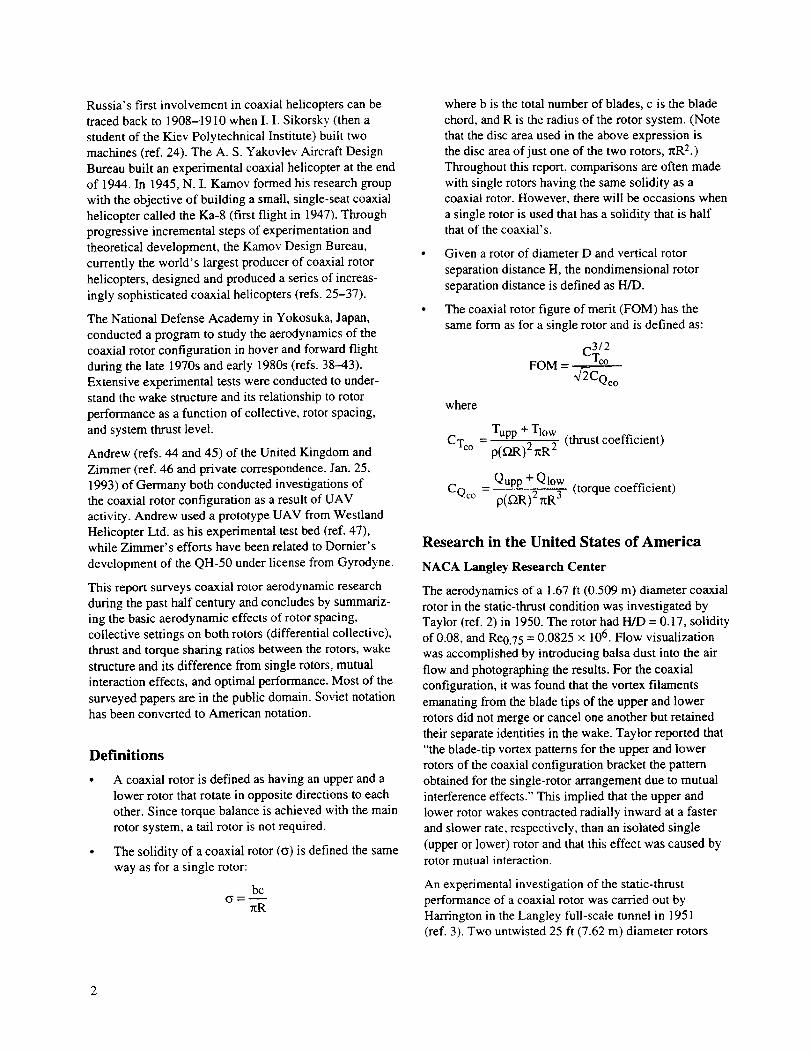
14 Comparison of the coaxial with other helicopter types (ref. 31) ......................................................................
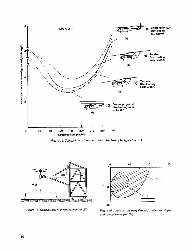
15 Coaxial rotor in a wind tunnel (ref. 27) ............................................................................................................
16 Areas of "unsteady flapping" motion for single and coaxial rotors (ref. 34) ..................................................
17 Ka-32 blade separation distance as a function of advance ratio (ref. 34) ........................................................
18 Calculated velocity field for the vortex ring condition, H/D = 0.10, v = 0.2 (ref. 28) ....................................
19 Calculated velocity field for edgewise flow in longitudinal/vertical plane, H/D = 0.10, _ = 0.10
22 3/rev vertical vibration of the Ka-50 at an unspecified location (ref. 33) ........................................................
23 Effective increase of coaxial rotor disc area (ref. 32) ......................................................................................
24 Experimental results for coaxial and equivalent solidity, single rotors in hover, D = 8.2 ft (2.5 m),H/D not reported (ref. 32) ................................................................................................................................
25 Comparison of overall helicopter efficiencies (ref. 32) ...................................................................................
26 National Defense Academy experimental apparatus (ref. 39) .........................................................................
27 Tip vortices from both the upper and lower rotor were seen to have a faster axial speed when
compared to Landgrebe's predictions, H/D = 0.105 (ref. 39) ..........................................................................
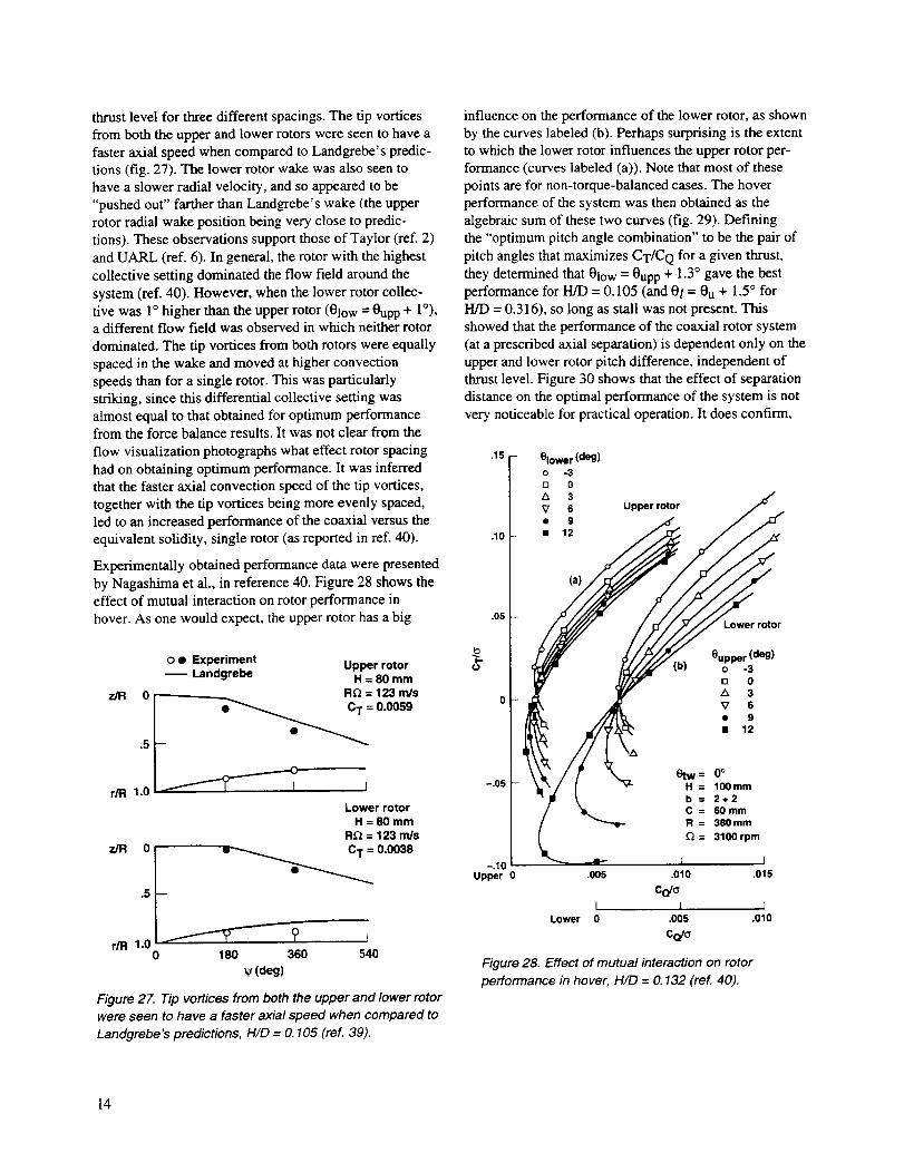
28 Effect of mutual interaction on rotor performance in hover, H/D = 0.132 (ref. 40) ........................................
29 System hover performance, H/D = 0.132 (ref. 40) ..........................................................................................
Page
1
3
3
8
10
10
10
11
11
11
12
12
12
12
12
13
13
14
14
15
30 Effectofseparationdistanceontheoptimal performance of the hovering system (ref. 40) ...........................
31 Wake model for a coaxial rotor in hover (refs. 41 and 43) ..............................................................................
32 Rotor mutual interaction factors, developed from references 41 and 43 .........................................................
33 Effect of axial spacing on optimum thrust and power ratios (refs. 41 and 43) ................................................
34 Simplified sketches of typical flow visualization results (refs. 41 and 43) .....................................................
35 An example of computed wake geometry at H/D = 0.10 (refs. 41 and 43) .....................................................
36 Comparison of theoretical (ref. 42) and experimental (ref. 39) static-thrust performance,H/D =0.13 ........................................................................................................................................................
37 Performance characteristics as a function of advance ratio, showing large influences of
upper rotor on lower, H/D = 0.316 (ref. 38) ....................................................................................................
38 Comparison of optimum pitch angle differences (ref. 38) ...............................................................................
39 Optimum coaxial vs. single rotor performances in hover and forward flight (ref. 38) ....................................
40 Hover theory (ref. 45) ......................................................................................................................................
41 Comparison of Landgrebe and coaxial rotor wake limits (ref. 44) ..................................................................
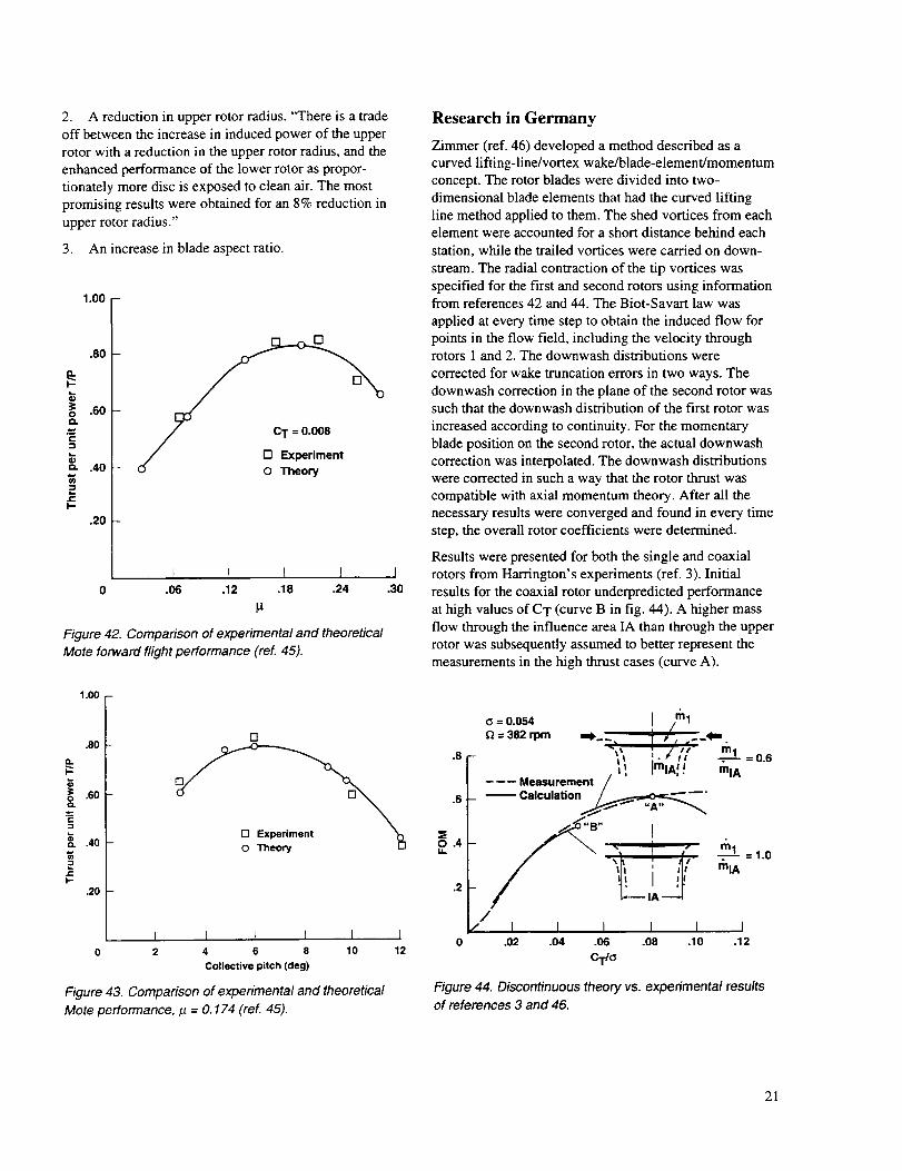
42 Comparison of experimental and theoretical Mote forward flight performance (ref. 45) ...............................
43 Comparison of experimental and theoretical Mote performance, p. = 0.174 (ref. 45) .....................................
44 Discontinuous theory vs. experimental results of references 3 and 46 ............................................................
45 Static-thrust prediction incorporating automatic contraction of tip vortices ...................................................
15
15
16
17
17
17
18
18
18
19
19
20
21
21
21
22
vi
Nomenclature
b
CQ
(CQpr)CO
CT
c
Cd
Clo
D
FOM
H
H/D
Io
Kr i
k, k', k"
kpr
kT
F
O
R
Re0.75
r
T
T
V
W
W
number of blades
torque coefficient
coaxial rotor profile-drag torque
coefficient
thrust coefficient
blade chord
profile-drag coefficient
average blade-lift coefficient
rotor diameter
rotor figure of merit
vertical rotor separation distance
nondimensional rotor separation
distance
induced power correction coefficient
circulation of fluid at each station in
wake
axial velocity influence factors,
functions of axial spacing
influence of taper on torque coefficient
influence of taper on thrust coefficient
total induced power
rotor torque
rotor system radius
Reynolds number at 75% rotor radius
radial distance
rotor thrust
thrust/weight ratio
forward velocity of helicopter
vertical descent velocity of helicopter
axial velocity of fluid
Z
£1
_2
rl
rl.
0
0tw
g
V
V
{PY
{Tp
P
_g
f_
03
Subscripts
co
1, low
0
u, upp
vertical distance
contraction ratio of upper rotor wake
at lower rotor
thrust loss due to rotation of fluid in
rotor wakes
power loss due to rotation of fluid in
rotor wakes
overall helicopter efficiency
blade taper ratio = Croot/Cti p
rotor collective angle
blade twist angle
nondimensional wake velocity
advance ratio = V/_R
descent ratio = W/DR
power sharing ratio (figs. 33 and 35)
tail rotor loss coefficient
transmission efficiency coefficient
air density
rotor solidity = bc/nR
thrust sharing ratio between
rotors = Tlow/Tup p
inflow angle
azimuthal position of rotor blade
rotational speed of rotors
swirl velocity of fluid
coaxial
lower rotor
outer region of rotor or wake
upper rotor
vii
A Survey of Theoretical and Experimental Coaxial Rotor
Aerodynamic Research
COLIN P. COLEMAN
Ames Research Center
Summary
The recent appearance of the Kamov Ka-50 helicopter
and the application of coaxial rotors to unmanned aerialvehicles have renewed international interest in the coaxial
rotor configuration. This report addresses the aero-
dynamic issues peculiar to coaxial rotors by surveying
American, Russian, Japanese, British, and Germanresearch. (Herein, "coaxial rotors" refers to helicopter,
not propeller, rotors. The intermeshing rotor system
was not investigated.) Issues addressed are separationdistance, load sharing between rotors, wake structure,
solidity effects, swirl recovery, and the effects of having
no tail rotor. A general summary of the coaxial rotor
configuration explores the configuration's advantages
and applications.
Introduction
In 1859, the British Patent Office awarded the first
helicopter patent to Henry Bright for his coaxial design,as shown in figure 1 (ref. 1). From this point, coaxial
helicopters developed into fully operational machines aswe know them today. The Kamov Design Bureau has
Figure 1. Henry Bright's 1859 coaxial design patent
(ref. 1).
historically led the design and production of these designsfor civilian applications and the Soviet Navy; moreover,
the appearance of the Kamov Ka-50 helicopter proved
that the coaxial rotor configuration could be applied to
military attack helicopters. Western trends, however,have concentrated on single main rotor/tail rotor, tandem
rotor, and synchropter devices. An exception to this is
shipboard launched short-range unmanned aerial vehicles(UAV), such as the Israeli Hellstar, where the need for
vertical takeoff and landing capability combined with
stable handling characteristics has renewed interest in the
coaxial configuration.
According to Lambermont (ref. 1), the Hiller AircraftCompany produced the first successful American coaxial
helicopter in 1944. Hiller went on to produce the XH-44,
which was followed by Bendix (Models K and J),
Hoppicopter, Brantly, Roteron, and Jenson. When Bendix
dissolved in 1949, they sold their Model K to the National
Advisory Committee for Aeronautics (NACA) LangleyResearch Center for rotor research work and their Model J
to the Gyrodyne Company of America. During the 1950s,
NACA Langley used their rotor as part of a program to
investigate the general characteristics of multiple-rotor
configurations in the Langley full-scale tunnel, which was
also supplemented by small-scale model tests (refs. 2--4).Gyrodyne continuously worked to improve the coaxial
rotor helicopter concept over a number of years (ref. 5).
After converting the Bendix Model J to the Model 2C,
problems arose such as vertical rudders and differential
collective failing to provide adequate yaw control inautorotation. March 1953 saw the idea of using "tip
brakes," which solved this problem. Gyrodyne went on
to develop the XRON and YRON series, followed by the
QH-50 series, which served as a remotely controlled,
weapon-carrying drone used for antisubmarine warfare.
Over 700 QH-50s were subsequently built and delivered
to the U.S. Navy. The Gyrodyne concept is currently
being pursued under license by Dornier GmbH(Germany) and Israeli Aircraft Industries, Ltd. (Israel).
The coaxial rotor concept was also pursued by Sikorsky
Aircraft via the advancing blade concept (ABC)
helicopter, which culminated in two flight vehicles
(refs. 6-23).
Russia'sfirstinvolvementincoaxialhelicopterscanbetracedbackto1908--1910whenI. I. Sikorsky(thenastudentoftheKievPolytechnicalInstitute)builttwomachines(ref.24).TheA.S.YakovlevAircraftDesignBureaubuiltanexperimentalcoaxialhelicopterattheendof 1944.In 1945,N.I.Kamovformedhisresearchgroupwiththeobjectiveofbuildingasmall,single-seatcoaxialhelicoptercalledtheKa-8(firstflightin 1947).Throughprogressiveincrementalstepsofexperimentationandtheoreticaldevelopment,theKamovDesignBureau,currentlytheworld'slargestproducerofcoaxialrotorhelicopters,designedandproducedaseriesofincreas-inglysophisticatedcoaxialhelicopters(refs.25-37).TheNationalDefenseAcademyinYokosuka,Japan,conductedaprogramtostudytheaerodynamicsofthecoaxialrotorconfigurationinhoverandforwardflightduringthelate1970sandearly1980s(refs.38--43).Extensiveexperimentaltestswereconductedtounder-standthewakestructureanditsrelationshiptorotorperformanceasafunctionofcollective,rotorspacing,andsystemthrustlevel.Andrew(refs.44and45)oftheUnitedKingdomandZimmer(ref.46andprivatecorrespondence,Jan.25,1993)ofGermanybothconductedinvestigationsofthecoaxialrotorconfigurationasaresultofUAVactivity.AndrewusedaprototypeUAVfromWestlandHelicopterLtd.ashisexperimentaltestbed(ref.47),whileZimmer'seffortshavebeenrelatedtoDornier'sdevelopmentof theQH-50underlicensefromGyrodyne.
in power for a given thrust (fig. 2). This scale effectwas lessened for tip speeds of 450 and 500 ft/sec,
(Re0.75 = 1.1 x 10⁶ and 1.3 × 10⁶, respectively). Differ-
ential collective pitch was also applied to both rotors to
deliberately create a non-torque-balanced coaxial system.This resulted in a 2% increase in power compared with
the torque-balanced data. Figure 3 summarizes
Harrington's figure of merit results for rotor 1. Thecalculated difference is due to a difference in solidity
(0.027 vs. 0.054) and not due to a difference in rotor
configuration.
Both rotors 1 and 2 were compared with the equivalent
solidity, single-rotor theory, and both show the sametrend. Figure 4 shows the results of rotor 2 testing,
together with theory comparison. The hovering theory
did remarkably well in the prediction of the single rotor'shovering performance, and was only slightly in error for
.006
.005
.004
CT.003
.002
.001
_ 1.0 f.8
Coaxial
.6-
_O .4 (half solidity of coaxial)
I I I " I I I I I I I.0002 .0004 .0006 .0008 0 .02 .04 .06 .08 .10 .12 .14
C o Crl°
Figure 2. Scale effect on rotor I performance at 327 ft/sec,H/D = 0.093. Lines drawn through data (ref. 3).
Figure 3. Effect of sofidity on rotor figure of merit (ref. 3).
Or
.009 -
.008 -
.007 -
.006 -
.005 -
.004 -
.003 -
.002 -
.001 -
Configuration o QR(ft/sec)
O Coaxial 0.152 392[] Coaxial 0.152 327O Single lower 0.076 262
A__Singlelower 0.076 39_2f
.0002 .0004 .0006 .0008 .0010
CQ
Figure 4. Comparison of theoretical (solid line) andexperimental static-thrust performance of rotor 2,
H/D = O.080 (ref. 3).
the coaxial rotor for most of the thrust coefficients tested.
On average, the theory predicted about 5% more power
required for a given thrust than was shown in the experi-mental results, and this difference decreased to zero at the
highest thrust coefficients tested. Because of the accuracy
with which the theory predicted the two different singlerotors, it was inferred that any difference between the
coaxial experiment and single-rotor theory was the result
of an aerodynamic anomaly that is not present in single
rotors. However, Harrington did not state this, and it was
generally accepted that the single-rotor theory was good
enough for coaxial performance prediction.
The validity of the single-rotor theory was questionedby Dingledein (ref. 4); he proposed that the tips of the
lower rotor would stall at high thrust coefficients and
would therefore not be modeled. A recomparison of
the equivalent single-rotor theory with experimental
coaxial measurements (using rotor 1 from Harrington's
experiments) showed the same results as above
(Re0.75 = 1.3 × 10⁶). He concluded that the equivalent
solidity, single-rotor theory was sufficient (within thebounds of experiment accuracy) to use as a performance
prediction method for a coaxial rotor in hover.
The forward flight performances of single and coaxial
rotors were also obtained by Dingeldein (ref. 4) using
rotor 1. The tests were performed at constant thrust
coefficient and rotor speed for various advance ratios
(fig. 5). The theoretical predictions for a single rotor
a_eed well with the experimental single rotor. It was
found that up to 14% more power was required for the
coaxial rotor than for a theoretical single rotor of
equivalent solidity under the same conditions. It wasconcluded that this difference was caused by increases
in both profile and induced losses associated with
interference effects. Analysis methods employed at that
time (ref. 48) could not model this effect. Dingeldeinconcluded, "the indications remain, however, that the
coaxial arrangement tested required more power inforward flight than an equivalent single rotor, although
there are certain advantages to the configuration which
may offset the larger power requirement in certain
applications."
De Lackner Helicopters, Inc.
Development problems with the De Lackner DH-4
Aerocycle in the late 1950s led to a flight demonstration
accident at about 16 knots. Speculative reasons for the
accident included the coaxial rotors striking each other
(because of blade bending) and uncontrollable longi-
tudinal oscillations. In 1959, the Aerocycle was tested
in the Langley full-scale wind tunnel (ref. 49). The
objectives of this test were to measure forces, moments,
and static stability derivatives to find a probable causefor the crash, and to compare theory with experimental
results. It was found that the forward speed was limited
by an uncontrollable pitching moment, and that the tipclearance between the rotors was always sufficient. The
blade-element/momentum-based theory of the isolated
100
80 [
e-
60
O
i.o 40
rr (
2O
CT = 0.0048; _R = 469 fps
- -- Calc
rl
- D _//Meas.-coaxml rotor
_single rotor
Figure 5. Experimental results and equivalent sohditysingle rotor theory for/eve/flight, G(coaxial) = 0.054,
G(sing/e) = 0.027, H/D = 0.093 (ref. 4).
I I !.300 .10 .20
P
rotor system showed that "rigid-rotor pitching moments
and static-stability derivatives may be predicted with
reasonable accuracy, provided that a longitudinal inflow
variation is assumed. Omission of the longitudinal inflow
variation in some cases leads to large errors."
Sikorsky Aircraft
The ABC rotor system, consisting of two coaxial
counterrotating hingeless rotors with a small rotor
spacing, took advantage of the aerodynamic lift potential
of the advancing blades. At high speeds, the retreating
blades were unloaded, with most of the load being carried
on the advancing sides of both rotors, thereby eliminating
the penalties of retreating blade stall (fig. 6).
Developmental work began in 1965 at the United Aircraft
Research Laboratories (UARL) which included small-
scale rotor tests and theoretical studies. Reference 7
summarizes this preliminary research, including several
experiments using a 4 ft (1.22 m) diameter rotor. Hover
testing (ref. 6) was carried out during which collective,
rotor spacing, and inter-rotor phase angle were altered.
Performance data and flow visualization pictures were
taken in order to compare coaxial with single rotors.
Vortices from the upper rotor were seen to move radially
inward and downward faster than vortices from the lower
ABC Lift distribution
ingle rotor
Figure 6. Schematic of the advancing blade concept
(ref.7).
rotor. Figure 7 shows performance data at an unspecified
rotor spacing. Total power for the coaxial rotor experi-
ment was 3-9% less than the equivalent single-rotor
theory; these results are comparable to those obtained
by Harrington (ref. 3). It was inferred that there was a
beneficial effect on total performance which was
attributed to reduced swirl velocity in the rotor wake,
although this conclusion can not be justified based on the
experimental results. It was also concluded that rotor
spacing had little effect on performance (although only
two different rotor spacings were tested). Forward flight
performance and blade stress characteristics were
examined with a 1/10-scale rotor with dynamically scaled
blades. Forward speeds from 60 to 180 knots were tested,
with spacings between H/D = 0.07 and H/D = 0.10;
no significant effects on performance or stress were
observed.
The prototype XH-59A was designed for 14,500 lb
(64,500 N) gross weight, maximum forward speed of
230 knots using a 40 fl (12.19 m) diameter rotor with
-10 ° nonlinear twist. Development of the rotor was
reported in reference 9.
The XH-59A rotor was tested in the NASA Ames 40-
by 80-Foot Wind Tunnel and reported in 1971 (refs. 8
and 9). Advance ratios tested were from 0.21 to 0.91.
Reference 8 includes the theoretical modeling of the
rotor, in which the top rotor has a uniform induced
velocity based on one-half of the system's lift, while the
Configuration (_
[] Upper rotor 0.082.14 -- O Lower rotor 0.082
• Coaxial rotor 0.164
.12 -- Theory
.10 --
_p..08
o .06
.04
.02
I I
0 .004 .008 .012 .016
cda
Figure 7. Comparison of theoretical and experimental
static-thrust performance of model ABC rotor, H/D not
reported (ref. 7).
lower rotor experiences the sum of the upper rotor's
induced velocity (undeveloped wake) plus its owninduced velocity. No differential pitch was used to
compensate for the difference in yawing momentsbetween the two rotors. Figure 8 (from ref. 8) compares
the "dual rotor theory with wake interference" with rotor
measurements. Dual rotor theory was shown to be an
improvement over the single-rotor theory, especially atlow advance ratios, where one would expect the influence
of the upper rotor to be the greatest. No significant
differences were seen in the prediction of drag for the
rotor system. Reference 8 concluded that "the comparison
of single and dual rotor torque, as predicted by themethods herein, indicates a performance benefit (torque
reduction) for the dual rotor over that of a single rotor of
equivalent disc loading. Thus, it appears that the perfor-mance benefits obtained by operating the upper rotor in a
more favorable velocity field are more significant than the
performance decrement caused by operating the lowerrotor in the downwash of the upper rotor." Comparing
figure 8 with figure 5, we see that this result is in
disagreement with Dingledein's result (ref. 4). Wakeinterference effects were also examined using twodifferent wake models. The first model included a wake
in which the lower rotor was subjected to a noncontract-
ing upper rotor wake. The second model included awake in which the lower rotor was subjected to a fully
developed upper rotor wake over the inboard 50% of the
rotor, thus simulating a high degree of wake contractionand acceleration. Predicted torque associated with this
second method of calculation was reduced, indicating that
greater performance efficiency could be obtained whenoutboard sections of the lower rotor escape upper rotor
downwash. Reference 8 also concluded that "single rotor
theory may be used as a simple method of calculating
coaxial rotor performance so long as inflow variations,
differential control inputs, and blade geometry differencesare considered second order effects."
In 1973, a 1/5 Froude scale model ABC was tested at the
Princeton University Dynamic Model Track (ref. 10). The
test examined the low-speed dynamics and aerodynamics
of the ABC coaxial rotor helicopter (from hover to
I.t= 0.1). This range was of particular interest becauserotor-induced velocity was large relative to forward speedso that mutual interference effects on the airframe were
substantial. Static and dynamic tests were carried out, aswell as a vibration evaluation. The tests confirmed the
high level of cyclic control power predicted by theoryand showed that selection of the proper control system
phasing permitted trimming of the ABC from hoverthrough transition. No significant vibration problemswere encountered at low advance ratio.
.008
.O06
.o04
o
.002
-.002
----O---- Test data
................ Single rotor theory
.... Dual rotor theory withwake interference
'- ,.:_
,... ........ .°.
_-'"_...; \'...
\_""
I E
.024
.O2O
A
"_ .016ov
._QO
_..012Q00
¢=
.oo8
.OO4
__ _R (Test)ft/sec= 650.__ _ V (Test)179knots= 165-
L 1 I I _0 .2 .4 .6 .8 1.0
Figure 8. Effect of rotor separation on ABC performance
prediction (ref. 8).
The first flight of the ABC aircraft (XH-59A) in pure
helicopter mode occurred July 26, 1973. The aircrafthad a 36 ft (10.97 m) diameter rotor, H/D = 0.069, total
rotor solidity of 0.127, blade taper ratio of 2:1 with-10 ° nonlinear twist, and disc loading of 10.3 lb/fl 2
(493 N/m2). On August 24, 1973, this first aircraft,
while flying at 25-30 knots at an altitude of about 50 ft
(15.24 m), pitched nose-up, lost altitude, and was
extensively damaged in a hard, tail-first landing.
A detailed accident investigation was subsequently
conducted, involving wind tunnel tests of a 1/5 Froude
scale model XH-59A aircraft. Results, projected to the
full-scale XH-59A aircraft, disclosed a significant
3 --
Flight test
o
I I I ]0 20 40 60 80
Airspeed (knots)
Figure 9. Underestimation of ABC rotor inflow at low
speed (ref. 11).
Preliminary design estimate
O Flight 6
,82 - [] Flight 10
[]
O_ .78" .76
,74 --
.72 [ t I I.07 .08 .09 .10 .11
CT/_
Figure 10. Flight test rotor figure of merit for XH-59A in
OGE hover (ref. 13).
I.12
difference between the analytically assumed fore-and-aft
variation of inflow through the rotors and the actual
inflow. The empirical "Glauert term" used to define this
effect (cos _ variation) significantly underestimated the
actual conditions (fig. 9, ref. 11). Consequently, more
forward longitudinal cyclic pitch was required for a given
(low-speed) trim condition than had been predicted.
Unfortunately, the forward longitudinal cyclic stick travelwas deliberately rigged to prevent pilot overcontrol of the
aircraft. The flight control system was then modified inthe second test aircraft to essentially double the longi-
tudinal and lateral cyclic control ranges. The first flight
with this modified flight control system occurred in
July 1975.
Continued expansion of the flight envelope was reportedin references 12-16. Reference 13 reported on an
XH-59A flight test during which the aircraft was tethered
to the ground. Hover performance both in and out of
ground effect (OGE) was obtained in terms of power and
gross weight coefficients. In calculating the rotor perfor-mance, it was assumed that the download on the fuselage
was 6% of the rotor thrust, and that transmission and
accessory losses resulted in a 95% transmission effi-ciency. From these assumptions, a plot of OGE rotor
figure of merit versus CT/O was obtained (fig. 10).However, because of these loss estimates, the accuracy
of these rotor performance results is questionable.Sudden lateral accelerations in gound effect were also
experienced during these flight tests (ref. 20) which wereattributed to a Karman vortex street shedding from the
cylindrical fuselage. This was counteracted by adding
small strip spoilers along the fuselage.
Following completion of flight tests in the pure helicopter
mode, two turbojet engines were added for auxiliary
forward thrust in a high-speed configuration, and results
from these flights are reported in references 19-21
and 23. In support of this, the 1/5 Froude scale model
was tested at NASA Langley to evaluate the complete
auxiliary propulsion speed envelope up to the 325 knot
dive speed (ref. 17).
In 1980, the ABC was tested in the Ames 40- by 80-Foot
Wind Tunnel to evaluate a rotor head drag reduction
fairing and rotor/tail/propulsion system interference
alleviation (ref. 22). Tests were conducted for advanceratios from 0.25 to 0.45 with the rotor on, and for free-
stream velocities from 60 to 180 knots.
The ABC was never placed into production.
Research in Russia
Russia is the world's largest user of coaxial rotor
helicopters. Their knowledge of the design can beattributed to both the work done by the Kamov Design
Bureau and the research conducted by the Central
Aerohydrodynamics Institute (TsAGI). Despite theextensive Soviet research, very few Soviet works have
been translated and published in the West; only recentlyhas some of this material been released. This section,
therefore, summarizes only the reports that are currently
available in this area (refs. 24-37).
Coaxial rotor aerodynamic theory is mentioned in two
translated Soviet texts published in the West, "Theory of
the Lifting Airscrew" (ref. 25) and "Helicopters" (ref. 26).
The first of these covers a wide spectrum of analyticalmethods which include modeling blades by both lifting
line and vorticity surfaces, using various wake types (free
wakes and cylindrical wakes with skew angles from 0°
to 90°), and applying vortex (Joukowsky) theory. These
methods are simplified in "Helicopters" with an emphasis
on obtaining practical application tools. Rotor blades are
modeled solely by single lifting lines, and rotor wakes are
assumed to be cylindrical in both hover and climb and flat
in forward flight.
"Helicopters" proposes that the overall aerodynamic
characteristics for the coaxial rotor can be found by
treating it as an equivalent solidity, single rotor. This
results in:
CQco =(CQpr)co +0"79CTco 3/210
where (CQpr)CO is the coaxial rotor profile-drag torque
coefficient, and lo is an induced power correction
coefficient, which reflects nonuniformity of the down-
wash (fig. 11). Assuming that the blades are tapered, the
coaxial rotor profile torque coefficient is given as:
(CQpr)co = 1 kpr_Cdo
I o
1.12
1.10
1.08
1.06
1.04
1.02
1.01
Croot
Ctip
Ctip
I I I i I0 2 4 6 8 10
Otw(deg)
Figure 11. Induced power correction coefficient vs. blade
linear twist for various taper ratio values (ref. 26).
where kpr is a taper ratio influence coefficient (fig. 12),
cr is the solidity of one of the two rotors making up the
coaxial system, and Cdo is the profile-drag coefficient at
zero lift. For tapered blades, the thrust coefficient is
given as:
CTc o = 0.313kT_Clo
where the k T coefficient reflects taper influence (fig. 12),
and C/o is the average blade-lift coefficient.
These performance predictions were compared against
Harrington's experiments (ref. 3) by Stepniewski et al. in
figure 13 (ref. 31). Very similar results were achieved,
and Stepniewski concluded that "'Helicopters' appears to
be sufficiently accurate for preliminary performance
estimates of coaxial rotors, assuming that the rotor tip
speeds are not so high as to generate considerable
compressibility effects outboard of the 0.7 blade station."
1.0
.9
.8
.7
.6
.5
..... kT
kpr
i= I I I2 3 4
rl*
Figure 12. Coefficients k T and kpr vs. blade taper ratio
(ref. 26).
1.0
.8
.6=EoI,,I.
.4
.2
I0 .14
Coaxial
I --'_" Single upper or lower
///
/o/Calculated according to Ref. 3
"¢/vI I I ! t ]
.02 .04 .06 .08 .10 .12
CT/C
Figure 13. Comparison of single rotor theory (ref. 26) with
experimental results (reL 3) as reported in reference 31.
"Helicopters" (ref. 26) also develops a rotor performance
estimate based on a separation distance of H/D = 0.1,
which is a typical value. The individual rotors weretreated as being in a climb, where the climb speed was
equal to the velocity induced by the other rotor (and
therefore different for each rotor). Solving for the
induced velocities, it was found that CTlow/CTupp = 0.86.Experiments by A. D. Levin (reported inref. 26)-on acoaxial rotor model of diameter 6.67 ft (2.034 m),
cy = 0.0445, HiD = 0.0985 with blades of-12 ° twist and
CT_ _ = 0.0036 gave CTI^,/CT, _ = 0.87. The mainconc_lusion derived herewas tl_[ "the average aero-
dynamic characteristics of a coaxial configuration are
practically independent of the distance between therotors." According to reference 26, this conclusion is said
to be confirmed by tests performed by Lessley reported
in TsAGI Report No. 31, 1941, by V. I. Shaydakov who
applied momentum theory (unreferenced) and also by
V. S. Vozhdayev who applied blade vortex theory(unreferenced). It was also concluded that the "distance
between rotors in the coaxial configuration affects only
the distribution of thrust between the upper and lower
rotors." Consequently, a coaxial rotor in axial flight is
treated as an equivalent solidity, single rotor, whileaccounting for the rotor mutual influence.
Forward flight phenomena in "Helicopters" were
interpreted with the help of the flat-wake concept.
Stepniewski (ref. 31) points out that this approach
is strictly limited to advance ratios in the range
1.63 C_ < l.t < 0.25. If a flat wake is used (with the
rotors generating the same torque), then it is assumedthat the thrusts must also be equal, since each rotor will
have an equal influence on the other. Experiments by
A. D. Levin (reported in ref. 26) using the same apparatus
as above found that for _ > 0.15 and equal torques
CTupp = 1.05 CTlow. By measuring induced velocities,Levin also found that increasing the separation distance
significantly reduced the influence of the mutuallyinduced velocities. For H/D = 0.0985, he stated that "the
induced power losses of the coaxial lifting system will be
21% lower than for a single rotor of the same diameter
and doubled solidity." He did not comment on the coaxial
rotor's parasite drag, nor on his method for finding theinduced power. Based on "Helicopters" approximations,
Stepniewski (ref. 31 ) compared the coaxial rotor withother helicopter configurations in forward flight (fig. 14).
He concluded that "from the power required per unit of
gross weight point of view, the classical coaxial heli-
copter with articulated rotors represents a configuration
which, in spite of higher parasite drag than that of
corresponding single-rotor or tandem machines, shows
an advantage in the engine power required in hover as
well as at low and medium flying speed ranges."
Another design method for coaxial rotors in axial flowwas reported by Kvokov (ref. 36). The rotors were
represented by lifting discs in which the circulationdistribution was constant in azimuth but varied with
radial position. A prescribed trajectory prepositioned the
wake vortices. Assuming an ideal, incompressible fluid,
expressions were obtained for the total induced velocity at
an arbitrary point in the flow. Two-dimensional blade-
element theory was used to calculate the lift and drag of
the rotors, with profile-drag losses and a tip loss factor
being added. The single-rotor wake geometry was alsocorrected to allow for the mutual interaction of the rotors
(this was done by trial and error in matching experimentalresults obtained at TsAGI, and are unreferenced).
Consequently, theoretical results were "tuned" to fit
the experimental data.
A coaxial rotor experiment was described by Antropov(ref. 27). Figure 15 shows a rotor of 6.56 ft (2 m)
diameter rotor with variable spacing (0.06 < H/D < 0.12)
used for axial flight testing. The rotor system can also be
tilted 90 ° into a vertical position, with the free-streamflow approaching edgewise, to simulate forward flight.
Results of tests conducted by A. D. Levin (reported in
ref. 27) using the above apparatus at H/D = 0.088 showed
that the effect of the upper rotor on the lower is muchgreater than the reverse, and that this difference decreases
with increasing advance ratio. The upper rotor was said tohave the largest effect on the lower rotor at an advance
ratio of 0.05, while the lower effects the upper the
greatest at an advance ratio of 0.1 (no explanation given).
The aerodynamic coupling between the two rotors is
strongly influenced by descending flight (ref. 34).
Extensive experimental and theoretical research was
carried out in the area of unsteady blade flapping motion
(this phenomenon was not exactly defined). Figure 16shows that this "unsteady flapping" motion is small
when compared to a single rotor for various forward and
vertical flight speeds. If such a reduction is possible, thenthe coaxial rotor configuration may possess blade vortexinteraction characteristics different from those of the
single-rotor helicopters in this condition. The minimum
separation distance between any two passing blades as a
function of advance ratio was also discussed by Anikin.
Figure 17 shows the blade separation for the Ka-32
(presumably from flight test). At low advance ratios, the
minimum distance occurs around _ = 270 ° (_5), and
Figure 20. 3/rev vertical vibration of the Ka-25 at the
center of gravity (ref. 37).
(a) 1 (b)
Upperrotor
Lowerrotor
Figure 21. Coaxial rotor phasing; (a) UL YSS-6 solution,
(b) flight test solution (ref. 37).
I
o1 J --
I I I0 50 100 150 200 250 300
V (kin/h)
Figure 22. 3/rev vertical vibration of the Ka-50 at an
unspecified location (ref. 37).
Soviet coaxial helicopter development as viewed fromRussia was summarized by Kasjanikov in 1990 (ref. 32).
He stated that coaxial features include a higher hovering
efficiency compared to a single rotor, absence of a tail
rotor, aerodynamic symmetry, and large deflections of
longitudinal and lateral control forces. High hover effi-
ciency is attributed to the mutual interference effectsof the rotors, an effective increase of the disc area caused
by extra clean air being drawn in by the lower rotor
(fig. 23), and a reduction of the swirl in the wake.
Experimental results obtained at TsAGI (unreferenced)
showed that the rotor figure of merit for the coaxial rotor
is much higher than for the single rotor of equal solidity
(fig. 24),
Hovering
I
L
Figure 23. Effective increase of coaxial rotor disc area
(ref. 32).
.9-
• 8 --
,7
:S
0.6 -
.5
• 4 --
.30
°single = _coaxial
_ Coaxial rotor
Single rotor
I L I.05 .10 .15
c_o
Figure 24. Experimental results for coaxial and equivalentsolidity, single rotors in hover, D = 8.2 ft (2.5 m), H/D not
reported (ref. 32).
12
70
e-QI
P=J 60
t,-
.__u
111
_- 5o
-'r
40.050
Ka-15 Ka-18_K__ KaXH'59A
.K:-32
CH-54 J
OH-SJ_UH-1E
I I.075 .100
CT/_
I.125
Figure 25. Comparison of overall heficopter efficiencies
(ref. 32).
although these results appear to be significantly higher
than those obtained by NACA and UARL. Helicopter
efficiency (as a whole) was defined as:
FOM _Tp_py
1-1= T3/2
where _T is the transmission efficiency coefficient, _pyP . -- ,
is the tail rotor loss coefficient, and T is the thrust/weight
ratio. Using this definition, several helicopter efficiencies
were compared in figure 25. Based on the above defini-
tion, Kamov estimated that the coaxial rotor helicopter
has an overall efficiency 17-30% higher than for single-
rotor helicopters.
Research in Japan
Experimental and theoretical research of the coaxial rotor
configuration was carried out by Nagashima and others
during the late 1970s and early 1980s (refs. 38-43). The
basis for this work lay in treating the coaxial rotor as a
type of variable geometry rotor (ref. 50). It was proposed
that the coaxial rotor wake could be optimized with an
appropriate selection of rotor parameters, which would
lead to an improvement in performance compared to an
equivalent single rotor. Experimental research utilized the
apparatus shown in figure 26. The rotor had a diameter of
2.49 ft (0.76 m), (y = 0.20 with rotor spacing in the range
H/D = 0.105 to 0.987. The rotor blades were untwisted, of
rectangular planform, with a NACA 0012 section and a
Figure 26. National Defense Academy experimental
apparatus (ref. 39).
blade chord of 0.197 ft (0.60 m). The rotor speed was
3100 rpm, giving Re0.75 = 0.38 x 10⁶. (This Reynolds
number is well below the value of 0.8 x 10⁶, which was
shown by Harrington (ref. 3) to have a performance offset
caused by scale effect.) Maximum disc loading for the
system was approximately 5.5 lb/fi 2 (263 N/m2). A
mixture of heated liquid paraffin and pressurized carbon
dioxide was injected into the flow near the tips of the
rotors to visualize the tip vortices.
Hover
A flow visualization study of the tip vortex geometry of
the above model coaxial rotor in hover was reported by
Nagashima et al. (ref. 39). A single four-bladed rotor was
first run in isolation at three different pitch settings, and
its tip vortex trajectories were found to be in good
agreement with the prescribed values of Landgrebe
(ref. 51). The coaxial rotor was then tested at the same
13
thrust level for three different spacings. The tip vortices
from both the upper and lower rotors were seen to have a
faster axial speed when compared to Landgrebe's predic-
tions (fig. 27). The lower rotor wake was also seen tohave a slower radial velocity, and so appeared to be
"pushed out" farther than Landgrebe' s wake (the upperrotor radial wake position being very close to predic-
tions). These observations support those of Taylor (ref. 2)
and UARL (ref. 6). In general, the rotor with the highest
collective setting dominated the flow field around the
system (ref. 40). However, when the lower rotor collec-
tive was 1° higher than the upper rotor (0low = 0upp + 1°),a different flow field was observed in which neither rotor
dominated. The tip vortices from both rotors were equally
spaced in the wake and moved at higher convection
speeds than for a single rotor. This was particularlystriking, since this differential collective setting was
almost equal to that obtained for optimum performancefrom the force balance results. It was not clear from the
flow visualization photographs what effect rotor spacing
had on obtaining optimum performance. It was inferredthat the faster axial convection speed of the tip vortices,
together with the tip vortices being more evenly spaced,led to an increased performance of the coaxial versus the
equivalent solidity, single rotor (as reported in ref. 40).
Experimentally obtained performance data were presented
by Nagashima et al., in reference 40. Figure 28 shows the
effect of mutual interaction on rotor performance in
hover. As one would expect, the upper rotor has a big
O • Experiment Upper rotorLandgrebe H = 80 mm
zJR 0 -- R_ = 123 rn/s
.5 _ _ 0 0059
Lower rotor
H =80mm
R_ = 123 m/s
.01 ?" I0 180 360 540
(deg)
Figure 27. Tip vortices from both the upper and lower rotorwere seen to have a faster axial speed when compared to
Landgrebe's predictions, H/D= O.105 (ref. 39).
influence on the performance of the lower rotor, as shown
by the curves labeled (b). Perhaps surprising is the extentto which the lower rotor influences the upper rotor per-
formance (curves labeled (a)). Note that most of these
points are for non-torque-balanced cases. The hover
performance of the system was then obtained as thealgebraic sum of these two curves (fig. 29). Defining
the "optimum pitch angle combination" to be the pair of
pitch angles that maximizes CT/C Q for a given thrust,
they determined that 0low -- 0upp + 1.3 ° gave the bestperformance for H/D = 0.105 (and 01 = 0u + 1.5 ° forH/D = 0.316), so long as stall was not present. This
showed that the performance of the coaxial rotor system
(at a prescribed axial separation) is dependent only on the
upper and lower rotor pitch difference, independent ofthrust level. Figure 30 shows that the effect of separation
distance on the optimal performance of the system is not
very noticeable for practical operation. It does confirm,
.15
.10
01owe r (deg)
o -3[] 0L_ 3
V 6• 9• 12
Upper rotor
t_
(J
.O5
(a)
Lower rotor
euppe r (dog)o -3[] 0Z_ 3V 6• 9• 12
(_IN= 0°-.05 H = 100mm
b = 2+2C = 60 mmR = 380mm
Q = 3100 rpm
-.10 I IUpper 0 .005 .010 .015
ColeI I J
Lower 0 .005 .010
Co/a
Figure 28. Effect of mutual interaction on rotor
performance in hover, H/D = O.132 (ref. 40).
14
.10 I Coaxial
H = 100 mm • (eupper, 0lower)
b = 4 0lower = constant
c -- 60 mm eupper = constant
R = 380 mm
0tw = 0 o
= 3100 rpm /
j (12,12)
j_" (9,12)(12,9) _,_ ....
.05 (9'9)_/_ 1_'_3'12)
I-- -- ._ (6,12)O "I
(0,1=)
(9,6),/_rj(0,9) /.-_. r_,,=J(6,6),_ _;'--;"
,_J_-(12,3)(6,3) _ (-3,6)
#7..((,,3),(=,o)_\/ \ I
0 _0) (9'0) .005 .010
(-3,0) (-3,3) CaJO"
Figure 29. System hover performance, H/D = O.132(ref. 40).
Coaxial _ H/D = 0.105
.10 - Otw = 0 .... H/D=0.210
b = 2+2
C = 60 mm
R = 380mm Z_
= 3100 rpm /_
2 blades
single rotor ,_//_
&.05 - /E \4bladeso r
single roto
I
0 .0050 .0100
Co/_
Figure 30. Effect of separation distance on the optima/
performance of the hovering system (ref. 40).
however, that the optimal hover performance of the
coaxial rotor is better than the hover performance of a
single four-bladed rotor for all separation distances
(approximately 6% less power for a given thrust at
H/D = 0.210). This is attributed to an appropriate choice
of pitch angle to improve the rotor flow field.
By examining all of the experimental data, it was found
that the thrust and torque sharing ratios were constant for
Upper rotor
Lower rotor
Boundary of
I /1 upper rotor1 wake
lJlII
Boundary of II
lower rotor _(
wake IIII I I
I_1 I dS3
,.R3
dS30
Figure 31, Wake mode/for a coaxial rotor in hover
(refs. 41 and 43).
differential pitch angles equal to those obtained above for
optimal performance. These pitch settings (and hence
optimal performance) always gave a torque balancebetween the two rotors that was independent of thrust
level and separation. The thrust sharing ratio at these
conditions was also independent of the thrust level, but
was dependent on separation distance.
Theoretical models for the performance prediction of a
coaxial rotor in hover were developed by Nagashima andNakanshi (refs. 41, 43) using both actuator disc and free-
wake analyses. Figure 31 shows the rotors modeled asactuator discs with their respective wakes that take
account of contraction and swirl. The inner part of the
lower rotor (region 2) experiences a downwash from the
upper rotor (region 1), while the outer part of the lowerrotor (region 20) experiences an upwash. The far wake
was designated regions 3 and 30. The rotors are divided
into a number of annular elements, across which pressureand swirl are discontinuous. The incremental thrusts at
each annular element are obtained in terms of the pressure
jumps across the rotors and the swirls in the wakes. This
leads to equations (A) and (B), which describe the rela-tions between the axial and rotational velocities in the
wakes of a hovering coaxial rotor:
15
] , -½co21w 3 _ ._-_col Kr !2 w 1 w 3
•I 21]Kr2w30 = _-_ 0_20 _-co30 Kr20
2 L w20 w30
where w is the axial velocity of fluid,co is the swirl
velocity of fluid, X"2is the rotational speed of rotors, and
Kri is the circulation of fluid at each station in the wake.Primed quantities denote values at the lower surface of
their respective rotor.
Thrust and power coefficients are expressed as:
CT = 8_.2(1 + x)+_:l
Cp = 1-_x {2_,1 + (7: - o0-_Q-} + _2
where
CT =
(A)
03)
T
prcR2(D.R) 2 , Cp =/tpR2(D.R) 3
( P = total induced power)
)_1 - wl _,2 - w2 w3-'_" , -_-, _3:aR '
w3_...__O= 2)_20)_30 = O.R
where cz is the contraction ratio of the upper rotor
wake at the lower rotor and "_is the thrust sharing
ratio = Tlow/Tup p. The thrust and power losses causedby rotation of the fluid in the wakes (el and e2,
respectively) are ignored as they are considered tobe of small order.
One interesting aspect of this work is the modeling of themutual interactions between wakes and rotors, which are
included by defining nondimensional axial velocities ateach rotor as:
?_2 = _l + k_u , _-20 = _-I + k"_u
3.u and _l are nondimensional induced velocities of the
The influence factors k, k" and k" are functions of the
axial spacing and are denoted by:
2H/D 1k=l+ k'=2-k k"=--
_l+4H 2/D 2 ' , _-
and are shown in figure 32. Factors k and k" were
derived from the potential theory for a uniformly loaded
actuator disc (ref. 48), whereas k" was derived from
experimental results (ref. 39) to adequately model theupwash effects of the contracted upper rotor wake on the
outer part of the lower one. As can be seen, 3.1 decreases
with increasing spacing as there is less induction from the
lower rotor; _,2 increases with increasing spacing, since
the contraction of the upper rotor wake causes the axial
velocity to increase, which then impacts the lower rotor;
and _,20 decreases with increasing spacing, since the
amount of upwash decreases with increasing spacing.
The optimal performance was then "formulated as a
calculus of variation problem with movable boundaries todetermine the far wake axial and swirl velocities distribu-
tions which minimize the total induced power, subject to
a given total thrust and constraints given by equations
(A and B)." The optimal performance was determined by
applying:
These "optimal conditions" led to the axial velocities in
the outer wake, w20 and w30, being exactly zero at any
separation distance. This implies that the wake of thelower rotor will be coincident with that of the contracted
upper rotor wake, and the outer part of the lower rotor
will operate as if it were in autorotation. Figure 33 shows
16
O
e-.m
oo,.
c
2e-
1.0
.5
e ormance'°°__" ul'efs"4"
Experimental results, ref 40
0 e u = 6° e I = 7 °
• eu = 8o e I = 9 °
-+- Levin, ref. 26
0 Figure 35, refs.41, 43
I I I I.25 .50 .75 1.00
HID
Figure 33. Effect of axial spacing on optimum thrust and
power ratios (refs. 41 and 43).
the computed effects of axial spacing on the optimal
thrust and power sharing ratios, and these effects are
compared with experimental results (ref. 40). The experi-mentally obtained result of A. D. Levin (ref. 26) is also
shown in figure 33, and it compares favorably with both
the actuator disc and experimental results. Simplifiedsketches of flow visualization results are shown in
figure 34. By observing the traces of smoke particles, it
was found that the axial velocity in the tip region of the
lower rotor could vary from upwash to downwash
depending on the thrust sharing ratio. It was therefore
argued that the condition of zero axial velocity at thisouter region could be obtained, and that this would equate
to optimal operating conditions, as shown in figure 34.
This condition would also give a uniform induced
velocity distribution in the far wake, which, by the
generalized momentum theory, would equate to minimal
induced power of the system. However, in practice, sucha uniform velocity distribution would not be obtainable.
Nagashima et al. (refs. 41 and 43) noted that the optimal
thrust sharing ratio was roughly equal to the contraction
ratio of the upper rotor wake at the lower rotor.
In order to treat the rotor mutual interactions in more
detail, nonlinear vortex theory with a simplified free-
wake analysis was applied. The rotor blades were
modeled by a lifting line with a uniform circulation
distribution, while the wakes consisted of a finite number
of discrete circular vortices. Wake geometries for a
_V 1-" ]_ W20< 0
NN/V2 _2
//W20 = W30 = 0
W30 < 0
W3Optimal condition
W 3 W 3
W20 > 0
W30 > 0
Ou = 6, OI = 5 Ou = 6, 01=7.5 Ou= 6, 01=9.5
Figure 34. Simplified sketches of typical flow visualizationresults (ref. 43).
coaxial rotor with a diameter of 6.56 ft (2 m) and chord
of 0.26 ft (0.08 m) at 500 rpm were calculated for
several separation distances, all for the same total thrust.
Figure 35 is the "near optimum" condition, with the wake
trajectories almost coincident, power sharing ratio near
unity, and thrust sharing ratio of 0.88 (which is close to
the contraction ratio of the upper rotor at the lower rotor).
This calculated value is also plotted in figure 33 andfound to be in good agreement. Also notice how the
movement of the tip vortices of the lower rotor are
predominantly radial in nature.
r(L)/R0 .5 1.0
I I I
Z/R
r(U)/R0 .5 1.0
.5
1.0
x = 0.880
H/D = 0.100
v = 0.988
I I
Figure 35. An example of computed wake geometry at
H/D = O.10 (refs. 41 and 43).
17
,10 --Upper rotor
A O ExperimentTheory ./
r rotor
/5_ /C_ _ = 324.5 rad/sec
0tw = 0 o
.005 .010
cda
Figure 36. Comparison of theoretical (ref. 42) and
experimental (ref. 39) static-thrust performance,
H/D = O.13.
Local momentum theory with a modified Landgrebe
wake (ref. 51) was applied to a coaxial rotor in hover by
Saito and Azuma (ref. 42). The influence of the lower
rotor on the upper rotor was modeled using the charts of
reference 48; for a given separation distance, these charts
yielded the extra induced velocity through the upper rotor
from the lower rotor. Annular vortices were used to
model the effect of upwash on both rotors. Figure 36
shows that the results of Saito and Azuma correlated
well with the experimental results of Nagashima et al.
(ref. 39).
Forward Flight
A study of the aerodynamics of a coaxial rotor system inforward flight was made in 1977 by Shinohara (ref. 38)using the same experimental apparatus as in reference 39
with both coaxial and single rotors. Figure 37 graphically
shows the large influence that the upper rotor has on the
lower. Increasing advance ratio causes the upper rotor
wake to be "swept back." This results in more of the
lower rotor being exposed to clean air, which leads to
better performance. Figure 38 shows that the optimal
differential pitch setting decreased from hover by about
0.5 ° with both increasing advance ratio and spacing.
Figure 39 compares a coaxial rotor system at various
spacings with a two- and four-bladed (equivalent solidity)
single rotor in hover and at _ = 0.16. The improvement in
coaxial rotor performance over the equivalent solidity,
single rotor is more evident with increasing advance ratio
(due to the convection of the tip vortices). Again, this is
.01o
.008
-_ .oo6(J
.004
.lO
.o8
.O6
.o4
.02
0
.02
.04
Co-axialH = 240 mm
= 0.1 + 0.1RQ = 123.4 m/sec
0u = 9 o CT/O
(9",1oo) 0_s
(90's°) "-. 0"_
_'(,', ;°).....a
o'".-"" "'" _"°'"°_/:g_, El"
! / s ds ,,,0' ,¢ /
:::H/" /(90, 90)
. / /. (9 o, 9 o) (9 °, 10°}+
....0 ._ _._--- (9o,9°): ..... 0.- A .-_
-- Upper rotor.... Lower rotor
...... .._......._''" (9°, s o)
I0 .04
.oo2 I I I I.08 .12 .16 .20
Figure 37. Performance characteristics as a function of
advance ratio, showing large influences of upper rotor on
Figure 38. Comparison of optimum pitch angle differences
(ref. 38).
18
.10
_v...05c3
R_ = 123.4m/see J 1
0.1
f-7
/f _ 2-bladed single rotor
f" Co-axial WD = 0.105
m _ Co-axial WD = 0.210.............. Co-axial H/D = 0.316n--m 4-bladed single rotor
I I0 .005 .010
cd_
Figure 39. Optimum coaxial vs. single rotor performances
in hover and forward flight (ref. 38).
in disagreement with the results of Dingledein (ref. 4),
but does follow the same trend as the ABC (ref. 8).
Saito and Azuma (ref. 42) also applied their local
momentum theory approach to forward flight. The
hovering theory was modified by considering the wakes
to be skewed vortex cylinders with no wake contraction.
Their calculated performances agreed well with the
experimental results of Shinohara (ref. 38) at an advance
ratio of 0.16 for H/D = 0.210 and 0.316. However, there
was a significant overprediction of performance for
H/D = 0.105 (approximately 7% less power for a given
thrust), which was attributed to disregarding the wake
contraction.
Research in the United Kingdom
In the mid-1970s, Westland Helicopters Ltd. began
experimenting with small axisymmetric remotely
controlled coaxial helicopters. The first of these was
named Mote, and its handling qualities were outlined in
reference 47. Mote had a teetering rotor of 5 ft (1.52 m)
diameter, tip speed of 236 ft/sec (72 m/sec), and total
mass of 33 lb (15 kgm).
Andrew (refs. 44 and 45) conducted an experimental and
theoretical investigation of coaxial rotor aerodynamics at
the University of Southampton in the early 1980s using a
stripped-down version of Mote. The model was tested
in both hover and forward flight modes with smoke
visualization to observe the tip vortices of each rotor.
The theoretical hover analysis used was called a
vortex/momentum/blade-element approach, which was
a blade-element/momentum approach with a vortex
representation of the tip vortex. The tip vortex wake was
discretized into a series of straight line filaments that
were either made to follow the prescribed paths of
reference 51, or were "relaxed" using a free-wake option.
Semiempirical equations were developed for the initial
viscous vortex core size and maximum swirl velocities.
Hover theory was based on figure 40, in which the tip
wake from the upper rotor impinges on the lower rotor at
a radial distance R c. The total induced velocity at any
position r on the upper rotor (Wiu(r)) was composed of
several components:
Wiu(r) = Wmu(r) + Wvu(r) + Wvl(r) ; 0 < r < R u
where
Wmu(r)
Wvu(r)
Wvl(r)
= induced velocity from strip theory
= induced velocity from upper tip vortex wake
= induced velocity from lower tip vortex wake
The outer part of the lower rotor which takes in clean air
had an inflow given by:
Wil(r" ) = Wml(r" ) + Wvl(r" ) + Wvu(r" ) ; R c < r" < R 1
where
Wml( r" )
Wvl(r")
Wvu(r")
= induced velocity from strip theory
= induced velocity from lower tip vortex wake
= induced velocity from upper tip vortex wake
Upper disc | Wiu = Wmu + Wvu + Wvl
.---¢-- R,,/wit= Wiu _ '
Lower°,scWm,+
"--------_ RI _
Figure 40. Hover theory (ref. 45).
19
The inflow for the lower rotor, which was immersed in
the wake from the upper rotor, was:
Wil(r') = Wiu(r) (Rc/Ru) 2 ; 0 < r' < Rc (C)
where r' = r (Rc/Ru) from continuity. This, however,failed to take into account the effect of the pressure
jump across the lower rotor, which results from the lift
generated on the lower rotor. An elemental stream tube
that passed through both rotors was considered, with
radius r on the upper rotor and radius r' on the lowerrotor. This stream tube generated a thrust dT(r), where:
dT(r) = 4_pr[wv(r) + Wim(r)] Wim(r) dr (D)
where wv(r) was the induced velocity from both upper
and lower tip vortex wakes combined, and wire(r) was the
strip theory value for the induced velocity.
But:
dT(r) = dTu(r) + dTl( r" ) (E)
Therefore, equating (D) with (E), and using (C), yielded
a quadratic in Wim(r), which was solved for. Hence, the
inflow angle (@) at any blade element was evaluated from:
_b(r) = (wv(r) + wire(r)) / f2r
A comparison of the experimentally obtained wake
trajectories with that of the Landgrebe prescribed wake
for a single rotor showed stronger and weaker contraction
of the upper and lower wakes, respectively (fig. 41).(Although not shown, it is presumed that this is also
accompanied by an increase in axial velocities; this would
be in agreement with Russian and Japanese observations.)
The prescribed wake was subsequently modified to allow
only for an increased axial translation of the upper rotorwake as it traversed the lower rotor (ref. 45). In compari-
son with experiment, the theory underpredicted the torquefor a given thrust, which was attributed to neglecting thecirculation distribution outside the vortex core in the
vortex induced velocity calculations. The theory was used
to predict the performance of a four-bladed single rotorwith a solidity equivalent to Mote's. In this case, for a
given thrust, the coaxial absorbed approximately 5% less
power than the equivalent single rotor. These increaseswere attributed to:
1. The contraction of the upper wake of a coaxial,
which allowed clean air with a slight upwash to be
taken by the outboard sections of the lower rotor.Consequently, the effective coaxial disc area increases
with a corresponding reduction in induced power.
2. The vertical spacing of the rotors in the coaxial
layout, which lessened the severity of the total vortexinduced downwash, especially on the upper rotor.
0
100
A01
2oo
3OO
4OO
i
Landgrebe
• Upper rotor
O Lower rotor
Experiment
• Upper rotor
[] Lower rotor
A Single rotor
CT = 0.005
.70 .80 .90 1.00
Normalized blade radius
Figure 41. Comparison of Landgrebe and coaxial rotorwake limits (ref. 44).
3. "Swirl recovery," which was considered a secondary
effect for low disc loadings.
Forward flight theory employed the classical, skewed
cylindrical wake at high advance ratios, or a free-wake
analysis at low advance ratios (ref. 45). The effect of the
tip vortex was approximated by incorporating the vortexinduced velocity through the center of the disc. For the
classical, skewed-wake option, a further allowance was
made for the influence of the tip vortex wake on a
specified blade element by evaluating the downwash at
that element. Figures 42 and 43 show comparisons
between theory and experimental forward flight Motedata at a constant thrust coefficient of 0.008 and advance
ratio of 0.174, respectively. In both cases, the classical
wake option was found adequate for estimating the
overall performance of Mote.
An optimization study of the coaxial rotor in hover wasalso undertaken using the developed theory (ref. 45).
Three parameters were identified that would increase theefficiency (thrust generated per unit power) of the coaxial
over an equivalent solidity, single rotor:
1. Vertical spacing. The greatest gains were made up to
H/D = 0.05; thereafter, no "practical" gains resulted with
increasing separation distance.
2O
2. A reduction in upper rotor radius. "There is a trade
off between the increase in induced power of the upper
rotor with a reduction in the upper rotor radius, and the
enhanced performance of the lower rotor as propor-
tionately more disc is exposed to clean air. The most
promising results were obtained for an 8% reduction in
upper rotor radius."
3. An increase in blade aspect ratio.
1.00 -
a. .80 _ _l-lf _,__
o .60 -¢,,
e-
= j/ [] Experiment.40 - O Theory_J
2r-I-
.20 -
I I I ]
0 .06 .12 .18 .24
Figure 42. Comparison of experimental and theoretical
Mote forward flight performance (ref. 45).
I.30
1.00
.80
O.
p-
_= .60o
=:.40
,,q
I"-
[]
.2O
1 I I I t
4 6 8 10 12
Collective pitch (deg)
Figure 43. Comparison of experimental and theoretical
Mote performance, I_ = 0.174 (ref. 45).
Research in Germany
Zimmer (ref. 46) developed a method described as a
46. Zimmer, H.: The aerodynamic calculation of counter
rotating coaxial rotors. Proceedings of the 1 lth
European Rotorcraft and Powered Lift Forum,
Paper No. 27, Sept. 1985.
47. Faulkner, A. J.; and Simons, I. A.: The remotely
piloted helicopter. Vertica, vol. 1, 1977,
pp. 231-238.
48. Castles, W.; and de Leeuw, J. H.: The normal
component of the induced velocity in the vicinity
of a lifting rotor and some examples of its
application. NACA TN-2912, Mar. 1953.
49. Sweet, G. E.: Static-stability measurements of a
stand-on type helicopter with rigid blades,including a comparison with theory. NASA
TN D-189, Feb. 1960.
50. Landgrebe, A. J.; and Bellinger, E. D.: Experimental
investigation of model variable-geometry and
ogee tip rotors. Proceedings of the 29th
American Helicopter Society Forum,
Washington, D.C., May 1973.
51. Landgrebe, A. J.: An analytical and experimentalinvestigation of helicopter rotor hover perfor-
mance and wake geometry characteristics.
USAAMRDL Tech. Rept. 71-24, EustisDirectorate, USAAMRDL, Fort Eustis, Va.,
June 1971.
25
REPORT DOCUMENTATION PAGEForm Approved
OMB No. 0704-0188
Public reporting burden for this collection of information is estimated to average 1 hour per response, including the time for reviewing instructions, searching existing data sources,gathering and maintaining the data needed, and completing and reviewing the collection of information. Send comments regarding this burden estimate or any other aspect of thiscollection of information, including suggestions for reducing this burden, to Washington Headquarters Services, Directorate for information Operations and Reports, 1215 JeffersonDavis Highway, Suite 1204. Arlington. VA 22202-4302, and 1o the Office of Management and Budget. Paperwork Reduction Pr¢ect (0704-0188), Washingfon, DC 20503.
1. AGENCY USE ONLY (Leave blank) 2. REPORT DATE
March 1997
4. TITLE AND SUBTITLE
A Survey of Theoretical and Experimental Coaxial Rotor
Aerodynamic Research
6. AUTHOR(S)
Colin P. Coleman
7. PERFORMING ORGANIZATION NAME(S) AND ADDRESS(ES)