Page 1
A Survey on Microstrip Patch Antenna Parameters Enhancement
Techniques: A Progress in Last Decade
1Geeta Kalkhambkar, 2Rajashri Khanai, 3Pradeep Chindhi 1,2Electronics and Communication Engineering, 3Engineering, Electrical Engineering
1,2,3Shivaji University Kolhapur, Visvesvaraya Technological University, Belagavi, Shivaji University Kolhapur
[email protected] , [email protected] , [email protected]
Abstract—previous studies show that there are various techniques for improving the parameters of patch
antennas with a relevant theory behind every structural reform and its effects. This paper presents a survey on
recent patch antenna improvement techniques used by the researchers in last decade. The key parameters of the
patch antenna such as gain, directivity, and bandwidth are considered in this paper. Study of various patch
antenna advancement techniques evolved in this survey and their impact on other parameters of antenna is also
discussed wherever required. A separate section is dedicated to explain the individual parameter enhancement,
which facilitates the antenna designers to select a suitable method for a particular application. The possible
questions coming out of some of the references are mentioned to identify the gaps in the research and to find
the scope of improvement. Alternative probable methods of improvement are also mentioned at some places
wherever possible which makes this paper a ready reference for new researchers.
Keywords— Bandwidth (B.W), Gain, Directivity, Fractal, Artificial Magnetic Conductor (AMC),
Metamaterial
I.INTRODUCTION
Now days the product demands applications specific behavior where one parameter important in one
application need not necessarily required in other applications. The extensive efforts have been made in the past
literatures to find out the best suitable patch antenna performance boosting methods. Highlights in the recent
research papers are structural modifications to achieve the desired requirements. Gain, directivity and bandwidth
being the important parameters of any antenna the different approaches are provided for enhancing each
parameter individually. Recent technologies demanding the high bandwidth for some applications target their
antenna design methods for the bandwidth enhancement. In recent papers corner cuts or truncation and slotted
geometries are implemented to enhance bandwidth. The antenna in [1] achieved the bandwidth of 80.41% with
truncated corners. The insertion of U slot and truncated corners increased the bandwidth from 17.89% to 80.4%
[2]. The patch antenna radiator and the inclusion of similar shaped slot as that of the shape of radiator at the
ground plane improve the coupling and hence increase the bandwidth [3-4]. The different feeding methods
influences the bandwidth, the vertex feed method improves the bandwidth in [5].The literatures [6 and 8]
signifies the need for creating the band notches to avoid inter band interference by insertion of H and T shaped
slots at the ground plane. In literature [6] and [15] we observed one issue that the gain reduces with increase in
the bandwidth which is a liability. The solution to this problem can be found in [7] where an antenna is
equipped with the reflector consisting of crossed dipoles and defected ground is proposed. The Dual Radiative
Reverse Arrow Fractal (DRAF) is one where the size reduction as well as improved bandwidth is achieved [8].
An Ultra Wide Band (UWB) antenna with band notch behavior caused by the pair of L strips and a parasitic
element is presented in [9]. Split Ring Resonators (SRR) due to their negative permeability characteristics
provide the band notch behavior [10]. Ω shaped slot can also be used to create the band notches [11].
JASC: Journal of Applied Science and Computations
Volume 5, Issue 7, July /2018
ISSN NO: 0076-5131
Page No:242
ss
Textbox
1,3Shivaji University Kolhapur, 2Visvesvaraya Technological University, Belagavi
Page 2
The antenna bandwidth can be increased by using metal strips and a brief impedance matching network
[12] in a cognitive radio applications. A pair of L strips and asymmetric structures on both the sides of a feed [13]
provides band notch characteristics. In some wideband communication applications, while improving
bandwidth it becomes essential to remove the band notch in the gain plot, the shorting strips and stubs are
utilized [14] to remove the band notches. The camphered ground plane with the defect causes improvement in
the impedance matching [15]. In [7] it is difficult to improve gain and bandwidth just by observing the current
distribution; in [16] the Frequency Selective Surface (FSS) is made reconfigurable using diodes. A reconfigurable
antenna consisting of Electromagnetic Band Gap (EBG) cells and PIN diodes is constructed in [17] Four SRR
elements are used in [18] to increase the bandwidth. The SRR elements can be embedded in the ground plane to
achieve a multiband performance, two cross shaped slots are made reconfigurable with the help of a diode
switching to give a wideband performance [19]. Reconfigurable antenna with cross shaped slots and PIN diodes
giving ultra wide band behavior is proposed in [20]. In [21] a Koch fractal slot at the ground plane of a
monopole patch antenna is proposed which improved the bandwidth drastically. Triple band performance is
achieved with Koch slot at the ground plane [22]. The squire slot at the centre surrounded by the 4 small square
fractals merges the bands in the s-parameters [23] to give a super wideband behavior. The successive iterations
of the octagonal concentric fractal antenna improve the bandwidth [24], a notch on either sides of the feed line
ensures good impedance match. The Sierpinski fractal bowtie antenna with a balloon for impedance matching
and tri band performance is achieved in [25] a genetic algorithm is used for optimization. A log periodic antenna
iterated with different fractals is given in [26]; Giuseppe fractals provided good results compare to others with
good fidelity factor. The use of shorting pins and sleets can be used to improve the bandwidth. In [27] shorting
pins and sleets are used to eliminate the unwanted modes and to bring the peaks closer resulting in the increased
bandwidth. The radii of the shorting pin influence the bandwidth in [28]. The combination of shorting pins of
different radii and V shaped slot on a triangular patch achieved wideband performance [29]. Shorting pins
enhances the impedance bandwidth [30]. The triangular patch creates TM 10 and TM 20 modes [31]. A V
shaped slot creates additional modes [32-33]. A folded patch equipped with shorting pins and V shaped slot
gives wide bandwidth [34]. Shorting and folding of a patch with interdigitated slots is presented in [35].
Interdigitated slots increase the perimeter for the flow of current and thus improved bandwidth. The cognitive
radio communication demanding the wideband and narrowband antennas on one platform, the narrowband
Cylindrical Dielectric Resonator Antenna (CDRA) on a wideband antenna in [36] serves the cognitive radio
communication applications.
Parametric variations of four U shaped patches placed at some height from a base patch antenna
optimize the resonance [37] and gives the improved gain. An array of 4X4 patches of different sized square
shapes fed by two apertures with via in between the two aperture feeds provides the improved gain [38]. Metal
wall cavity surrounding the feed in an array of truncated corner provides high gain [39]. Inclusion of
metallization below the substrate in a spacer suspended patch antenna gives better results compare to the spacer
suspended antenna in which the metallization is placed above the substrate [40]. Two slotted patches placed at
some distance above the ground plane acts as a superstrate giving a dual band performance with enhanced gain
[41] and both the bands can be controlled independently by varying slot dimensions. S shaped metamaterial cells
arranged as a superstrate on a fabry parrot antenna [42] gives better gain compare to other metamaterial
structures. SingleNegative Metamaterials (SNMs) is used as a surface wave suppressor which increases the gain
[43]. In [44] triangular SRR with negative permeability is used for gain enhancement. A 4X4 array of Artificial
Magnetic Conductor (AMC) surface acting as a reflector [45] which improves the gain. Metasurface lens above
the patch antenna [46] enhances the gain. Coupling efficiency is improved with the help of indefinite
permeability metamaterial cells [47].
JASC: Journal of Applied Science and Computations
Volume 5, Issue 7, July /2018
ISSN NO: 0076-5131
Page No:243
Page 3
The stacked configuration of patches loaded with U slot and shorting pins [48] gives better gain. A
hybrid configuration with a horn shaped patch placed on a planar patch [49] increases the gain. A slot coupled
patch with Meta surface cavity and a reflector below the patch equipped with phase controlled cells of a diode
[50] enables the gain improvement. The reconfigurable EBG structure [51] is used as a reflector which gives the
frequency diversity and greater options for optimization. In the today’s world of miniaturization the fractal
antennas are gaining importance. The fact that fractal antennas improve the bandwidth with the reduced size
makes them a special candidate in wideband communication. The self similarity and space filling property are
the structural properties of a fractal antenna. Different types of fractal structures are available like Koch fractal,
Sierpinski, Hilbert fractal etc. Metamaterial structure at the ground plane with Koch slot gives multifrequency
operation. The partial ground plane neutralizes the inductive effect.
Few literatures have been reported in recent years on directivity enhancement. Some gain improvement
techniques also improves the directivity. Few methods of directivity increment are: including the reflector
behind patch antenna, implementing array of patches and insertion of fractals at the periphery of the patch
radiator. Metamaterial loop patch with the capacitive cuts [52] creates a directive beam. Differential Evolution
with Wavelet Mutation (DEWM) algorithm gives better analysis of the directivity [53]. Coupled feed of parasitic
patch and choke enhances the directivity; the reflector behind patch is used in [54]. Koch fractal iterations at the
periphery of the patch create localized modes [55] and improve directivity. [56] Uses a wideband planar AMC
surface for directionality. Mutual coupling reduction in an array based directional antenna is important. [57]
Uses the parasitic patch to reduce mutual coupling. Use of strips in between the adjacent patches and two square
shaped slots at the ground plane also reduces the mutual coupling and hence enhances the directivity. Simple
slots and the conducting strips at the ground plane reduces mutual coupling [58]. Fractal antennas [59] give
better performance in wideband with miniature size. Soft and gradual discontinuities in the fractal may provide
better performance in case of wideband fractal antennas [60].
This review is organized in a following order.
Section 1: Bandwidth enhancement techniques and comparison.
Section 2: Gain enhancement techniques and comparison.
Section 3: Directivity enhancement techniques and comparison.
Section 4: Conclusion
II. BANDWIDTH ENHANCEMENT TECHNIQUES
The studies have been reported to draw some direct or indirect conclusions to determine which factors
of patch antenna design and implementation are responsible for bandwidth enhancement, among which some
are listed below:
Bandwidth of the patch antenna increases with increase in a substrate thickness with some practical limit of 0.1
λο and decrease with increase in the dielectric constant .
Stacked configuration of patch antenna and use of foam substrate improves the bandwidth.
Different feeding configurations such as capacitive disc feed and feed with folded plates may also improve
bandwidth with proper selection of feed location.
Defected ground structures with parametric iterations may also yield the increase in the bandwidth.
Insertion of different shaped slots like V shaped slot results in bandwidth improvement.
Use of shorting pins.
JASC: Journal of Applied Science and Computations
Volume 5, Issue 7, July /2018
ISSN NO: 0076-5131
Page No:244
Page 4
Fractal antennas to improve bandwidth characteristics.
Truncated corners of patch antenna to improve bandwidth.
One common practice is observed in many references that, many of the researchers are doing the
parametric study by tuning the dimensions of antenna geometry to yield at the best possible outcome at their
level. We can call it as a “Tuning by Observations”. Since equations for antenna design are all empirical in nature,
such trial and error methods along with above mentioned techniques refine the result in a better way. In the
sections below some case studies are explained.
A. Bandwidth Enhancement by Slots and Corner Cuts
a) Slot Loaded Patch with Corner Cuts
Corner cuts or truncation and slots disturbs the current distribution in an antenna, every shape of slot
has its own contribution. The results may vary depending on the shape of antenna and shape of the slots. The
slots and corner cuts are used by some authors to enhance the impedance bandwidth. Slots follow the babinets
principle of optics for its operation. Corner cuts divert the current distribution and usually are used in the
antennas where bandwidth enhancement and polarization need to be improved. In [1] corner cuts along with
slots are used in ±45 dual Slant Polarized (SP) elements to enhance the impedance bandwidth. Dual polarized
SP element is formed with the help of two orthogonally placed dipoles with one corner cut and two slots on
each dipole head as shown in a figure 1(a). A bandwidth of 27% and an impedance bandwidth of 55.5% are
achieved. In [2] U-slot truncated corner rectangular patch antenna is designed and analyzed in IE3D software.
Truncated corners offer the capacitive effect and in a circuit model it remains in parallel with the radiating patch.
Truncated corners are made variable and tuned. The enhancement in the bandwidth, gain as well as efficiency is
observed. The antenna is operable in the S and C band with wide bandwidth of 80.41%, gain ranging from 9.32
dBi to 9.78 dBi and efficiency greater than 80% in the entire band. The truncated corners and U-slot directly
influence the bandwidth, gain, and efficiency. The notable point is that the bandwidth before the insertion of U-
slot and truncated corner was 17.39% and after insertion of U-slot and truncated corner it increased to 80.41%
the geometry is as shown in fig 1 (b).
Fig. 1 (a) Corner cuts and slots in a dual SP element (b) Truncated corners and U shaped slot
b) Slots and Defected Ground Structures to Improve Bandwidth
A U shaped patch antenna and circular ground loaded with an inverted U shaped slot is as shown in fig
2. In a conventional U shaped antenna usually a dual band performance is expected. The antenna in [3] shows a
wideband performance due to the strong coupling between the patch and the ground plane. The parametric
study is performed to fine tune the structure. A bandwidth of 100.35% is realized with the maximum gain of 3.1
dBi.
JASC: Journal of Applied Science and Computations
Volume 5, Issue 7, July /2018
ISSN NO: 0076-5131
Page No:245
Page 5
Itching of U shaped slot on the upper patch and the ground plane also provides a triple band behavior
[4]. The first band being created by the patch and other two by the U shaped slots.
An antenna with pentagonal parasitic patch and pentagonal slot at the ground plane with vertex feed is
proposed in [5]. The pentagonal antenna with side feed and vertex feed configuration is as shown in fig. 3(a).
The tuning is performed in order to have a better impedance matching at the entire band. The rotation of
pentagonal slot in the steps of 22.5o is performed. The better impedance matching is found at 0o and 180o. The
bandwidth is enhanced in vertex feed more than that of the side feed and can be observed in a fig. 3(c).
In the wideband multifrequency applications where a single antenna is used for multiple applications,
only obtaining wideband characteristics is not useful. In some applications the band notch need to be
purposefully created whereas in some cases the attempts are done to reduce the band notches.
The isolation between the bands can be obtained with the help of a band notch characteristics derived
with the help of parametric variation of H slot in a ground plane [6]. A bandwidth of 2.55GHz ranging from
1574.4GHz to 1576.4GHz with the band notches between 1574.4 GHz– 1576.4 GHz and 2402 GHz–2484
GHz is given [5]. The diagram and associated return loss plot is shown in fig. 4.
Fig. 2 U shaped patch surface and ground with U slot, view of antenna in [3] Circular
Fig. 3 Pentagonal slot antenna (a) Vertex feed and (b) Side feed (c) S11 plot showing bandwidth
The drawback in [5] is the maximum gain is below 2 dB and at some point it is negative. This work can
be extended by including a reflector behind the antenna to improve gain [7] where a reflector composed of FSS
structure is utilized. A T shaped slot is inserted to create a band notch to reduce the inter band interference [8]
for IEEE 802.11a applications. In [9] a pair of inverted L-shaped slot and two asymmetric structures along side
of feed line provides the triple band notch behavior. The complementary Split Ring Resonators (SRR) provides
the band notch behavior due to its negative permittivity [10] and is used in image frequency rejection. The band
notch created with the insertion of Ω shaped slot is illustrated in [11].
JASC: Journal of Applied Science and Computations
Volume 5, Issue 7, July /2018
ISSN NO: 0076-5131
Page No:246
Page 6
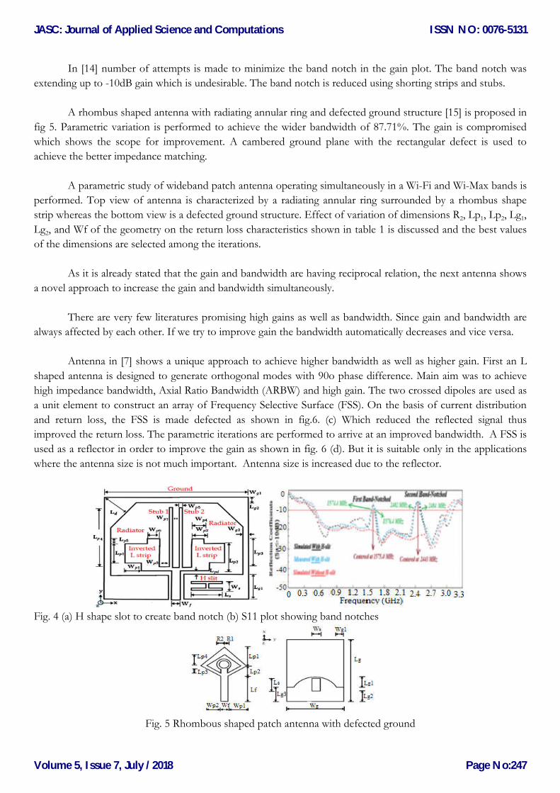
In [14] number of attempts is made to minimize the band notch in the gain plot. The band notch was
extending up to -10dB gain which is undesirable. The band notch is reduced using shorting strips and stubs.
A rhombus shaped antenna with radiating annular ring and defected ground structure [15] is proposed in
fig 5. Parametric variation is performed to achieve the wider bandwidth of 87.71%. The gain is compromised
which shows the scope for improvement. A cambered ground plane with the rectangular defect is used to
achieve the better impedance matching.
A parametric study of wideband patch antenna operating simultaneously in a Wi-Fi and Wi-Max bands is
performed. Top view of antenna is characterized by a radiating annular ring surrounded by a rhombus shape
strip whereas the bottom view is a defected ground structure. Effect of variation of dimensions R2, Lp1, Lp2, Lg1,
Lg2, and Wf of the geometry on the return loss characteristics shown in table 1 is discussed and the best values
of the dimensions are selected among the iterations.
As it is already stated that the gain and bandwidth are having reciprocal relation, the next antenna shows
a novel approach to increase the gain and bandwidth simultaneously.
There are very few literatures promising high gains as well as bandwidth. Since gain and bandwidth are
always affected by each other. If we try to improve gain the bandwidth automatically decreases and vice versa.
Antenna in [7] shows a unique approach to achieve higher bandwidth as well as higher gain. First an L
shaped antenna is designed to generate orthogonal modes with 90o phase difference. Main aim was to achieve
high impedance bandwidth, Axial Ratio Bandwidth (ARBW) and high gain. The two crossed dipoles are used as
a unit element to construct an array of Frequency Selective Surface (FSS). On the basis of current distribution
and return loss, the FSS is made defected as shown in fig.6. (c) Which reduced the reflected signal thus
improved the return loss. The parametric iterations are performed to arrive at an improved bandwidth. A FSS is
used as a reflector in order to improve the gain as shown in fig. 6 (d). But it is suitable only in the applications
where the antenna size is not much important. Antenna size is increased due to the reflector.
Fig. 4 (a) H shape slot to create band notch (b) S11 plot showing band notches
Fig. 5 Rhombous shaped patch antenna with defected ground
JASC: Journal of Applied Science and Computations
Volume 5, Issue 7, July /2018
ISSN NO: 0076-5131
Page No:247
Page 7
TABLE1. ENFLUENCE OF PARAMETRIC VARIATION IN FIG. 5
Dimensions
(mm) R2 Lp1 Lp2 Lg1 Wf
Designed 4.5 13 7 4.5 3
Modified 4.5 15 6.4 4.5 3
Effect
10 dB B.W
improvement
in both the
bands, first
band shifts
towards right
B.W remains
constant but
first band
shifts towards
left
10 dB B.W
improvement
in the second
band
Improves 10
dBB.W and
impedancematching
Impedance
matching
improves
In [16] a single layer FSS is made reconfigurable with the aid of diodes. An antenna with reconfigurable
Electromagnetic Band Gap (EBG) cells is used to provide frequency diversity [17]. Such type of
reconfigurability is used in [6] which will provide more options to experiment with the design for different
possibilities of outcome.
In [18] four parasitic elements are used to modify the antenna bandwidth by using the SRR. A quad band
performance is achieved in [19] where a SRR is embedded at the ground plane which exhibits negative
permeability property and a pair of C shaped slots on the semicircular patch surface.
In [20] the cross shaped slot at the ground plane produced an ultra wideband performance. The slots are
made reconfigurable with pin diodes. The antenna is aperture fed and gives high gain and circular polarization
too.
Fig 6 (a) Parasitic patch (b) Single element: crossed dipoles (c) Reflector (d) Antenna
Fig. 7 (a) Return loss (b) Axial ratio (c) Gain with and without FSS
c) Use of fractal geometries to enhance the bandwidth
A Koch iterated fractal is itched at the ground plane and front view of antenna is a monopole as shown
in fig 8(a). A great improvement in the bandwidth is seen from basic geometry to second iteration when the
antenna is iterated with Koch fractal iterations [21].
JASC: Journal of Applied Science and Computations
Volume 5, Issue 7, July /2018
ISSN NO: 0076-5131
Page No:248
Page 8
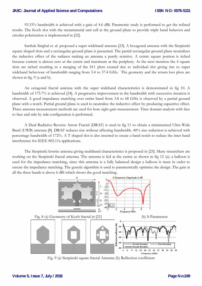
93.33% bandwidth is achieved with a gain of 4.6 dBi. Parametric study is performed to get the refined
results. The Koch slot with the metamaterial unit cell at the ground plane to provide triple band behavior and
circular polarization is implemented in [22].
Sarthak Singhal et. al. proposed a super wideband antenna [23]. A hexagonal antenna with the Sierpinski
square shaped slots and a rectangular ground plane is presented. The partial rectangular ground plane neutralizes
the inductive effect of the radiator making an antenna a purely resistive. A centre square portion is itched
because current is almost zero at the centre and maximum at the periphery. At the next iteration the 4 square
slots are itched resulting in a merging of the S11 plots created due to individual slot giving rise to super
wideband behaviour of bandwidth ranging from 3.4 to 37.4 GHz. The geometry and the return loss plots are
shown in fig. 9 (a and b).
An octagonal fractal antenna with the super wideband characteristics is demonstrated in fig 10. A
bandwidth of 175.7% is achieved [24]. A progressive improvement in the bandwidth with successive iteration is
observed. A good impedance matching over entire band from 3.8 to 68 GHz is observed by a partial ground
plane with a notch. Partial ground plane is used to neutralize the inductive effect by producing capacitive effect.
Three antenna measurement methods are used for bore sight gain measurement. Time domain analysis with face
to face and side by side configuration is performed.
A Dual Radiative Reverse Arrow Fractal (DRAF) is used in fig 11 to obtain a miniaturized Ultra Wide
Band (UWB) antenna [8]. DRAF reduces size without affecting bandwidth. 40% size reduction is achieved with
percentage bandwidth of 172%. A T shaped slot is also inserted to create a band notch to reduce the inter band
interference for IEEE 802.11a applications.
The Sierpinski bowtie antenna giving multiband characteristics is proposed in [25]. Many researchers are
working on the Sierpinski fractal antenna. The antenna is fed at the centre as shown in fig 12 (a); a balloon is
used for the impedance matching, since this antenna is a fully balanced design a balloon is must in order to
ensure the impedance matching. The genetic algorithm is used to parametrically optimize the design. The gain at
all the three bands is above 6 dBi which shows the good matching.
Fig. 8 (a) Geometry of Koch fractal in [21] (b) S-Parameters
Fig. 9 (a) Sierpinski square fractal Antenna (b) Reflection coefficient
JASC: Journal of Applied Science and Computations
Volume 5, Issue 7, July /2018
ISSN NO: 0076-5131
Page No:249
Page 9
Fig 10 (a) Octagonal Fractal antenna (b) Reflection coefficient
Fig 11 (a) Fractal antenna with DRAF (b) S11 plot
The log periodic fractal antenna is implemented in [26] the antenna is experimented with 4 types of the
fractal such as triangular Koch, square Koch , tree and Giuseppe fractal for UWB end fire radiation pattern. The
fidelity factor is observed at each stage. The choice is made between miniaturization and gain, the Giuseppe
fractal shows the good performance as shown in fig 13, the additional directors can be introduced to improve
gain. Spiral slots reduce interference between adjacent bands.
Fig. 12 (a) Sierpinski bowtie antenna (b) S11 plot showing triple band performance
Fig. 13 (a) Log periodic fractal antenna (b) S11 plot showing wideband performance
d) Effect of Slots and Shorting Pins to Enhance the Bandwidth
Slots and shorting pins provide the means to increase the bandwidth of patch antenna. Unwanted modes
between TM10 and TM30 of differentially fed patch antenna are removed with the help of sleets and shorting
pins is proposed in [27].
JASC: Journal of Applied Science and Computations
Volume 5, Issue 7, July /2018
ISSN NO: 0076-5131
Page No:250
Page 10
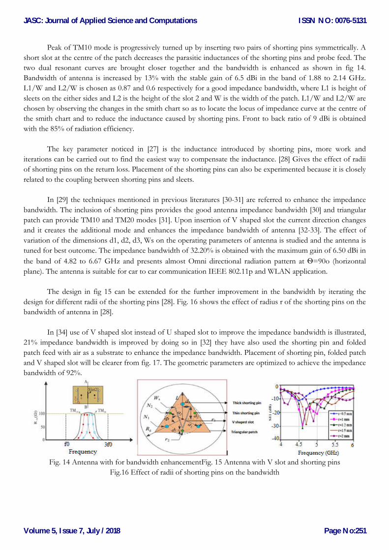
Peak of TM10 mode is progressively turned up by inserting two pairs of shorting pins symmetrically. A
short slot at the centre of the patch decreases the parasitic inductances of the shorting pins and probe feed. The
two dual resonant curves are brought closer together and the bandwidth is enhanced as shown in fig 14.
Bandwidth of antenna is increased by 13% with the stable gain of 6.5 dBi in the band of 1.88 to 2.14 GHz.
L1/W and L2/W is chosen as 0.87 and 0.6 respectively for a good impedance bandwidth, where L1 is height of
sleets on the either sides and L2 is the height of the slot 2 and W is the width of the patch. L1/W and L2/W are
chosen by observing the changes in the smith chart so as to locate the locus of impedance curve at the centre of
the smith chart and to reduce the inductance caused by shorting pins. Front to back ratio of 9 dBi is obtained
with the 85% of radiation efficiency.
The key parameter noticed in [27] is the inductance introduced by shorting pins, more work and
iterations can be carried out to find the easiest way to compensate the inductance. [28] Gives the effect of radii
of shorting pins on the return loss. Placement of the shorting pins can also be experimented because it is closely
related to the coupling between shorting pins and sleets.
In [29] the techniques mentioned in previous literatures [30-31] are referred to enhance the impedance
bandwidth. The inclusion of shorting pins provides the good antenna impedance bandwidth [30] and triangular
patch can provide TM10 and TM20 modes [31]. Upon insertion of V shaped slot the current direction changes
and it creates the additional mode and enhances the impedance bandwidth of antenna [32-33]. The effect of
variation of the dimensions d1, d2, d3, Ws on the operating parameters of antenna is studied and the antenna is
tuned for best outcome. The impedance bandwidth of 32.20% is obtained with the maximum gain of 6.50 dBi in
the band of 4.82 to 6.67 GHz and presents almost Omni directional radiation pattern at Ѳ=90o (horizontal
plane). The antenna is suitable for car to car communication IEEE 802.11p and WLAN application.
The design in fig 15 can be extended for the further improvement in the bandwidth by iterating the
design for different radii of the shorting pins [28]. Fig. 16 shows the effect of radius r of the shorting pins on the
bandwidth of antenna in [28].
In [34] use of V shaped slot instead of U shaped slot to improve the impedance bandwidth is illustrated,
21% impedance bandwidth is improved by doing so in [32] they have also used the shorting pin and folded
patch feed with air as a substrate to enhance the impedance bandwidth. Placement of shorting pin, folded patch
and V shaped slot will be clearer from fig. 17. The geometric parameters are optimized to achieve the impedance
bandwidth of 92%.
Fig. 14 Antenna with for bandwidth enhancementFig. 15 Antenna with V slot and shorting pins
Fig.16 Effect of radii of shorting pins on the bandwidth
JASC: Journal of Applied Science and Computations
Volume 5, Issue 7, July /2018
ISSN NO: 0076-5131
Page No:251
Page 11
Folded patch and miniaturization with the adjustable performance is the key feature given in [35], where
three techniques are used in order to improve the antenna performance shorting, folding and the inter
slots. shorting reduces both the resonant frequencies, folding in Shorted Slotted Patch (SSP) ensures the
miniaturization, interdigitated slots are implemented to increase the peri
the width of patch the lower resonant frequency was reduced and the higher frequency is fixed, it also provides
the options for optimization. A foam layer is inserted to give the structural support to the patch as sho
18.
There are certain challenges in the applications like cognitive radio communication where the antenna
assembly should contain a wideband antenna for spectrum sensing and a narrowband antenna for cognitive
radio communication such antenna is
Dielectric Resonator Antenna (CDRA) is implemented. UWB antenna is used for spectrum sensing and
narrowband CDRA antenna for cognitive radio communication. In [12] the monopole antenna is
TV white space cognitive radio communication with improved bandwidth by inserting two parasitic strips and
the impedance matching network itched on the patch itself.
Fig. 17 Antenna with V- shaped slot
B. Gain Enhancement Techniques.
The gain is an important parameter in any antenna. The patch antennas due to their structural limitation
suffer with low gain problems. Improving the gain is important with some restriction in the geometry like
miniaturization. Previous studies have shown
match increases the gain. In the next section some case studies are considered to elaborate the different gain
enhancement techniques employed by the researchers.
Some common practices to increase gain are listed below:
Array of metal elements on patch.
Creating metal wall cavity surrounding the feed.
Stacked configuration of patches with metallization at the bottom part of the substrate.
Including metamaterial and Ring Resonating (RR) structures
Backing cavity, reflector and MS lenses.
In [37] shorted planar U shaped patches are constructed to resonate at 2.4GHz WLAN and 3.5GHz
WiMAX bands. U shaped patch are parametrically varied in order to adjust the two bands, two larger U shaped
patches resonates at the higher frequency whereas two smaller patches create the resonance at lower frequency.
The two bands can be shifted to any application the gain of 8 dBi and 11 dBi at the two bands is reported. The
drawback in [25] is the increased size which
Folded patch and miniaturization with the adjustable performance is the key feature given in [35], where
improve the antenna performance shorting, folding and the inter
slots. shorting reduces both the resonant frequencies, folding in Shorted Slotted Patch (SSP) ensures the
miniaturization, interdigitated slots are implemented to increase the perimeter of current flow and to decrease
the width of patch the lower resonant frequency was reduced and the higher frequency is fixed, it also provides
the options for optimization. A foam layer is inserted to give the structural support to the patch as sho
There are certain challenges in the applications like cognitive radio communication where the antenna
assembly should contain a wideband antenna for spectrum sensing and a narrowband antenna for cognitive
radio communication such antenna is presented in [36]. UWB antenna combined with narrowband Cylindrical
Dielectric Resonator Antenna (CDRA) is implemented. UWB antenna is used for spectrum sensing and
narrowband CDRA antenna for cognitive radio communication. In [12] the monopole antenna is
TV white space cognitive radio communication with improved bandwidth by inserting two parasitic strips and
the impedance matching network itched on the patch itself.
shaped slot and shorting pinsFig. 18 Folded patch with inter digitized slots (a) Fro
view (b) Side view
The gain is an important parameter in any antenna. The patch antennas due to their structural limitation
suffer with low gain problems. Improving the gain is important with some restriction in the geometry like
miniaturization. Previous studies have shown that, reducing the surface waves and improving the impedance
match increases the gain. In the next section some case studies are considered to elaborate the different gain
enhancement techniques employed by the researchers.
se gain are listed below:
Creating metal wall cavity surrounding the feed.
Stacked configuration of patches with metallization at the bottom part of the substrate.
Including metamaterial and Ring Resonating (RR) structures.
Backing cavity, reflector and MS lenses.
In [37] shorted planar U shaped patches are constructed to resonate at 2.4GHz WLAN and 3.5GHz
WiMAX bands. U shaped patch are parametrically varied in order to adjust the two bands, two larger U shaped
onates at the higher frequency whereas two smaller patches create the resonance at lower frequency.
The two bands can be shifted to any application the gain of 8 dBi and 11 dBi at the two bands is reported. The
drawback in [25] is the increased size which cannot be avoided as shown in fig 19.
Folded patch and miniaturization with the adjustable performance is the key feature given in [35], where
improve the antenna performance shorting, folding and the inter-digitized
slots. shorting reduces both the resonant frequencies, folding in Shorted Slotted Patch (SSP) ensures the
meter of current flow and to decrease
the width of patch the lower resonant frequency was reduced and the higher frequency is fixed, it also provides
the options for optimization. A foam layer is inserted to give the structural support to the patch as shown in fig.
There are certain challenges in the applications like cognitive radio communication where the antenna
assembly should contain a wideband antenna for spectrum sensing and a narrowband antenna for cognitive
presented in [36]. UWB antenna combined with narrowband Cylindrical
Dielectric Resonator Antenna (CDRA) is implemented. UWB antenna is used for spectrum sensing and
narrowband CDRA antenna for cognitive radio communication. In [12] the monopole antenna is designed for
TV white space cognitive radio communication with improved bandwidth by inserting two parasitic strips and
patch with inter digitized slots (a) Front
The gain is an important parameter in any antenna. The patch antennas due to their structural limitation
suffer with low gain problems. Improving the gain is important with some restriction in the geometry like
that, reducing the surface waves and improving the impedance
match increases the gain. In the next section some case studies are considered to elaborate the different gain
Stacked configuration of patches with metallization at the bottom part of the substrate.
In [37] shorted planar U shaped patches are constructed to resonate at 2.4GHz WLAN and 3.5GHz
WiMAX bands. U shaped patch are parametrically varied in order to adjust the two bands, two larger U shaped
onates at the higher frequency whereas two smaller patches create the resonance at lower frequency.
The two bands can be shifted to any application the gain of 8 dBi and 11 dBi at the two bands is reported. The
JASC: Journal of Applied Science and Computations
Volume 5, Issue 7, July /2018
ISSN NO: 0076-5131
Page No:252
Page 12
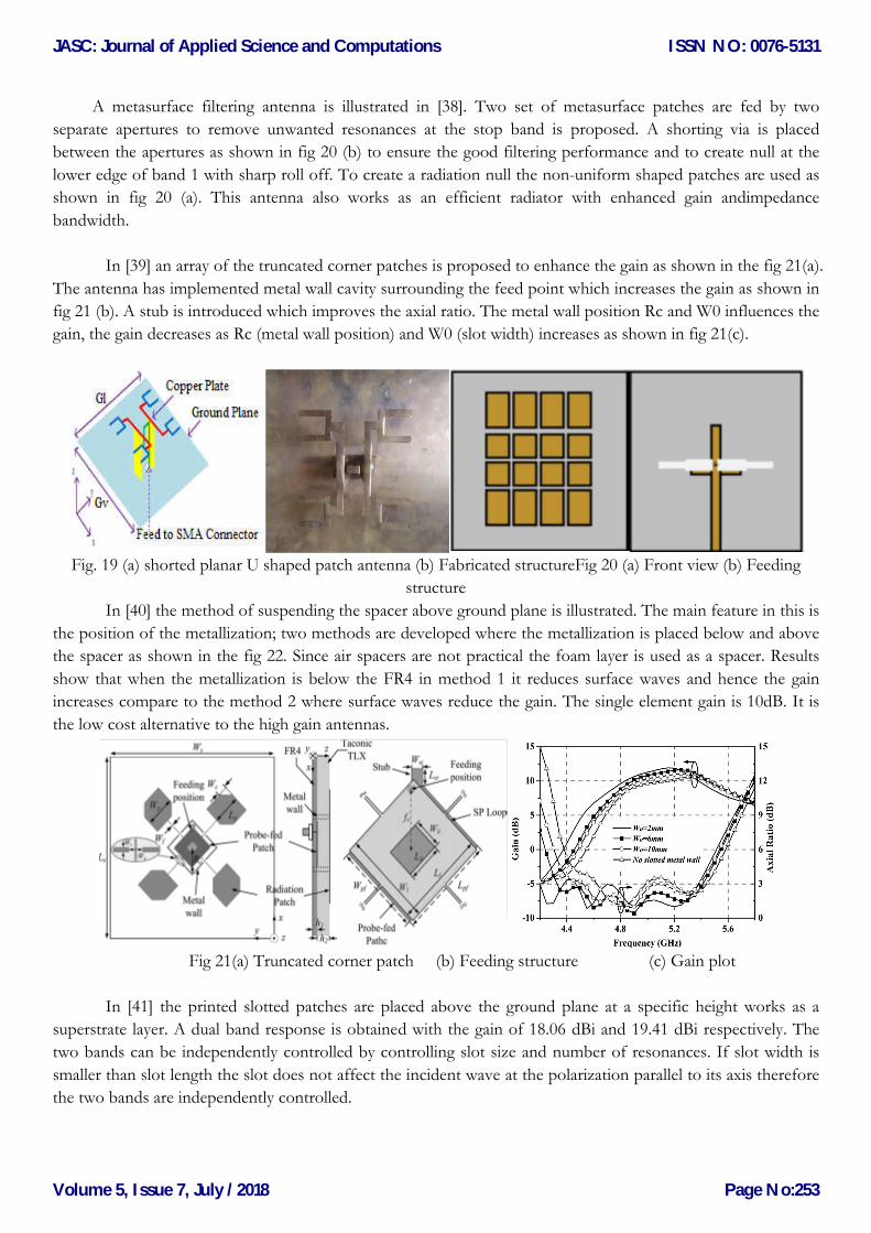
A metasurface filtering antenna is illustrated in [38]. Two set of metasurface patches are fed by two
separate apertures to remove unwanted resonances at the stop band is proposed. A shorting via is placed
between the apertures as shown in fig 20 (b) to ensure the good filtering performance and to create null at the
lower edge of band 1 with sharp roll off. To create a radiation null the
shown in fig 20 (a). This antenna also works as an efficient radiator with enhanced gain andimpedance
bandwidth.
In [39] an array of the truncated corner patches is proposed to enhance the gain as shown in the fig 21(a).
The antenna has implemented metal wall cavity surrounding the feed point which increases the gain as shown in
fig 21 (b). A stub is introduced which improves the axial ratio. The metal wall position Rc and W0 influences the
gain, the gain decreases as Rc (metal wall position) and W0 (slot width) increases as shown in fig 21(c).
Fig. 19 (a) shorted planar U shaped patch antenna (b) Fabricated structureFig 20 (a) Front view (b) Feeding
In [40] the method of suspending the spacer above ground plane
the position of the metallization; two methods are developed where the metallization is placed below and above
the spacer as shown in the fig 22. Since air spacers are not practical the foam layer is used as a sp
show that when the metallization is below the FR4 in method 1 it reduces surface waves and hence the gain
increases compare to the method 2 where surface waves reduce the gain. The single element gain is 10dB. It is
the low cost alternative to the high gain antennas.
Fig 21(a) Truncated corner patch (b) Feeding stru
In [41] the printed slotted patches are placed above the ground plane at a specific height works as a
superstrate layer. A dual band response is obtained with the gain of 18.06 dBi and 19.41 dBi respectively. The
two bands can be independently controlled by controlling slot size and number of resonances. If slot width is
smaller than slot length the slot does not affect the incident wave at t
the two bands are independently controlled.
A metasurface filtering antenna is illustrated in [38]. Two set of metasurface patches are fed by two
separate apertures to remove unwanted resonances at the stop band is proposed. A shorting via is placed
apertures as shown in fig 20 (b) to ensure the good filtering performance and to create null at the
lower edge of band 1 with sharp roll off. To create a radiation null the non-uniform
shown in fig 20 (a). This antenna also works as an efficient radiator with enhanced gain andimpedance
In [39] an array of the truncated corner patches is proposed to enhance the gain as shown in the fig 21(a).
enna has implemented metal wall cavity surrounding the feed point which increases the gain as shown in
fig 21 (b). A stub is introduced which improves the axial ratio. The metal wall position Rc and W0 influences the
all position) and W0 (slot width) increases as shown in fig 21(c).
Fig. 19 (a) shorted planar U shaped patch antenna (b) Fabricated structureFig 20 (a) Front view (b) Feeding
structure
In [40] the method of suspending the spacer above ground plane is illustrated. The main feature in this is
the position of the metallization; two methods are developed where the metallization is placed below and above
the spacer as shown in the fig 22. Since air spacers are not practical the foam layer is used as a sp
show that when the metallization is below the FR4 in method 1 it reduces surface waves and hence the gain
increases compare to the method 2 where surface waves reduce the gain. The single element gain is 10dB. It is
o the high gain antennas.
Fig 21(a) Truncated corner patch (b) Feeding structure
In [41] the printed slotted patches are placed above the ground plane at a specific height works as a
se is obtained with the gain of 18.06 dBi and 19.41 dBi respectively. The
two bands can be independently controlled by controlling slot size and number of resonances. If slot width is
smaller than slot length the slot does not affect the incident wave at the polarization parallel to its axis therefore
the two bands are independently controlled.
A metasurface filtering antenna is illustrated in [38]. Two set of metasurface patches are fed by two
separate apertures to remove unwanted resonances at the stop band is proposed. A shorting via is placed
apertures as shown in fig 20 (b) to ensure the good filtering performance and to create null at the
uniform shaped patches are used as
shown in fig 20 (a). This antenna also works as an efficient radiator with enhanced gain andimpedance
In [39] an array of the truncated corner patches is proposed to enhance the gain as shown in the fig 21(a).
enna has implemented metal wall cavity surrounding the feed point which increases the gain as shown in
fig 21 (b). A stub is introduced which improves the axial ratio. The metal wall position Rc and W0 influences the
all position) and W0 (slot width) increases as shown in fig 21(c).
Fig. 19 (a) shorted planar U shaped patch antenna (b) Fabricated structureFig 20 (a) Front view (b) Feeding
is illustrated. The main feature in this is
the position of the metallization; two methods are developed where the metallization is placed below and above
the spacer as shown in the fig 22. Since air spacers are not practical the foam layer is used as a spacer. Results
show that when the metallization is below the FR4 in method 1 it reduces surface waves and hence the gain
increases compare to the method 2 where surface waves reduce the gain. The single element gain is 10dB. It is
cture (c) Gain plot
In [41] the printed slotted patches are placed above the ground plane at a specific height works as a
se is obtained with the gain of 18.06 dBi and 19.41 dBi respectively. The
two bands can be independently controlled by controlling slot size and number of resonances. If slot width is
he polarization parallel to its axis therefore
JASC: Journal of Applied Science and Computations
Volume 5, Issue 7, July /2018
ISSN NO: 0076-5131
Page No:253
Page 13
Fig. 22 Metallization (a) below the FR4 epoxy (b) above the FR4 epoxy
In [42] a fabry parrot antenna loaded with metamaterial superstrate is presented for gain enhancement.
Metamaterial layer above the ground plane acts as a superstrate, it reflects the incident waves falling on it and
improves S11 characteristics and hence it also improves the gain. Various metamaterial cells are experimented
such as cross shaped, Ω-shaped, SRR and other, among which the S-shaped metamaterial cell offered good
performance in gain as well as bandwidth enhancement. The structure is arranged as shown in the figure 23(a).
The 8 dBi gain improvement is obtained; the overall gain is 10.7dB as shown in fig.23 (b).
In [43] the Dual layer Symmetry Single Ring Resonator Pair (DSSRP) fabricated on both the layers of an
antenna loaded with a Metamaterial (MTM) cells is proposed as shown in fig 24(b). MTM cells acts as a reflector.
Electromagnetic waves cannot propagate in Single Negative MTM (SNM) because of negative andμ. Thus
SNM’s are used as a surface wave suppresser. Gain is increased from 6.1 dB to 8.2 dB and narrower gain after
using the DSSRP. Triangular split ring resonators can also be used for negative permeability [44].
Fig. 23 (a) Fabry parrot antenna with metamaterial superstrate (b) Gain plot
In [45] polarization insensitive Artificial Magnetic Conductor (AMC) is designed, the AMC structure is a
planar array of annular ring slotted patches. A 4X4 array of AMC patches works as a reflector. The higher band
is tuned by varying the capacitance through the variation of width of a slot. Gain of the antenna is improved by
10 dB. The dual band performance is achieved, the first band is due to the circular slot and the second band is
due to the circular patch at the centre of circular slot as shown in fig 25. Annular ring provides the polarization
insensitivity in the design.
In [46] the small metasurface lens is utilized to increase the bore sight gain of the antenna. Metasurface
(MS) lens is placed at λ
distance above the source antenna as shown in fig 26. MS lens is constructed above the
circular substrate; the rectangular metallic rings are printed on the surface. MS lens can reduce the main beam
width and hence increases the bore sight gain. In [47] indefinite permeability metamaterial cells are used which
perform better than isotropic negative metamaterial cells in terms of coupling efficiency.
JASC: Journal of Applied Science and Computations
Volume 5, Issue 7, July /2018
ISSN NO: 0076-5131
Page No:254
Page 14
In [48] a stacked geometry of patches is implemented. The driven patch is loaded with the shorting pins
and U shaped slot as shown in fig 27. Due to the stacked configuration the antenna gai
between the driven patch and parasitic patch has significant effect on impedance matching because it directly
affects the coupling between two patches. As mentioned in [18] the effect of shorting pin dimensions on the
reflection coefficient can be experimented in [48]. The gain of 9.7dBi is reported in [48] but as we have already
mentioned the increased antenna size is also one disadvantage.
Fig 24 (a) Patch antenna with DSSRP MTM cellsFig 25 (a) antenna with AMC surface
AMC Fig. 26 Patch antenna with metasurface lens
In [49] a hybrid patch antenna with conical horn is proposed as shown in fig 28. A slot feeding
mechanism excites TM010 dominant mode, the horn has a great impact on gain enhancement wit
more on other antenna parameters. Patch radious and slot length has direct effect on the resonant frequency and
waveguide height controls the impedance matching and the gain. The gain of 12 dB is obtained with this
structure. But special fabrication technology is needed due to complexity.
In [50] a slot coupled microstrip patch is placed in an assembly of two metasurface, one acting as
absorber and another as a partially reflecting surface as shown in fig. 29. A tunable reflection phase cell
below the patch. The region surrounding the antenna exhibits a fabry parrot cavity and thus increases the
directivity. Dynamic frequency tuning with the help of controlled activity of a varactor diode is reported. A 7dB
of the gain is enhanced. Absorbing layer resistance and varactor diode resistance has direct effect on the gain.
The backing cavity with concentric ring SRR also provides the high gain characteristics [51].
Fig. 27 Stacked patch with U slot driven element. Fig. 28 Hybrid patc
In [48] a stacked geometry of patches is implemented. The driven patch is loaded with the shorting pins
and U shaped slot as shown in fig 27. Due to the stacked configuration the antenna gai
between the driven patch and parasitic patch has significant effect on impedance matching because it directly
affects the coupling between two patches. As mentioned in [18] the effect of shorting pin dimensions on the
coefficient can be experimented in [48]. The gain of 9.7dBi is reported in [48] but as we have already
mentioned the increased antenna size is also one disadvantage.
Fig 24 (a) Patch antenna with DSSRP MTM cellsFig 25 (a) antenna with AMC surface
Fig. 26 Patch antenna with metasurface lens
In [49] a hybrid patch antenna with conical horn is proposed as shown in fig 28. A slot feeding
mechanism excites TM010 dominant mode, the horn has a great impact on gain enhancement wit
more on other antenna parameters. Patch radious and slot length has direct effect on the resonant frequency and
waveguide height controls the impedance matching and the gain. The gain of 12 dB is obtained with this
rication technology is needed due to complexity.
In [50] a slot coupled microstrip patch is placed in an assembly of two metasurface, one acting as
absorber and another as a partially reflecting surface as shown in fig. 29. A tunable reflection phase cell
below the patch. The region surrounding the antenna exhibits a fabry parrot cavity and thus increases the
directivity. Dynamic frequency tuning with the help of controlled activity of a varactor diode is reported. A 7dB
bsorbing layer resistance and varactor diode resistance has direct effect on the gain.
The backing cavity with concentric ring SRR also provides the high gain characteristics [51].
Stacked patch with U slot driven element. Fig. 28 Hybrid patc
In [48] a stacked geometry of patches is implemented. The driven patch is loaded with the shorting pins
and U shaped slot as shown in fig 27. Due to the stacked configuration the antenna gain is increased. The height
between the driven patch and parasitic patch has significant effect on impedance matching because it directly
affects the coupling between two patches. As mentioned in [18] the effect of shorting pin dimensions on the
coefficient can be experimented in [48]. The gain of 9.7dBi is reported in [48] but as we have already
Fig 24 (a) Patch antenna with DSSRP MTM cellsFig 25 (a) antenna with AMC surface (b) single element of
In [49] a hybrid patch antenna with conical horn is proposed as shown in fig 28. A slot feeding
mechanism excites TM010 dominant mode, the horn has a great impact on gain enhancement without affecting
more on other antenna parameters. Patch radious and slot length has direct effect on the resonant frequency and
waveguide height controls the impedance matching and the gain. The gain of 12 dB is obtained with this
In [50] a slot coupled microstrip patch is placed in an assembly of two metasurface, one acting as
absorber and another as a partially reflecting surface as shown in fig. 29. A tunable reflection phase cell is placed
below the patch. The region surrounding the antenna exhibits a fabry parrot cavity and thus increases the
directivity. Dynamic frequency tuning with the help of controlled activity of a varactor diode is reported. A 7dB
bsorbing layer resistance and varactor diode resistance has direct effect on the gain.
The backing cavity with concentric ring SRR also provides the high gain characteristics [51].
Stacked patch with U slot driven element. Fig. 28 Hybrid patch with conical horn
JASC: Journal of Applied Science and Computations
Volume 5, Issue 7, July /2018
ISSN NO: 0076-5131
Page No:255
Page 15
Directivity Enhancement Techniques
The common practice in the previous researches to enhance the directivity is as given below:
To include a reflector behind the antenna [8].
Implementing array of patches
Insertion of fractals at the perimeter
Some case studies are given below.
In [52] the loop antenna with μ negative metamaterial cell for creating a directional beam is produced.
The horizontal arms of the loop are loaded with capacitive cuts as shown in fig 30. The superposition of the
parallel arm fields causes the increased current amplitudes and the antenna radiates in that direction. At the
central frequency the directionality of the antenna resembles the array of two dipoles. At higher frequencies the
antenna acts as a printed yagi antenna. Feeding arm acts as a driver and the patch strip acts as a director and the
directivity increases without adding any external reflector.
Fig. 29 Patch antenna embedded in a Fabry parrot cavityFig. 30 (a) Loop antenna with μ negative metamaterial
cells (b) Fabricated structure
In [53] an in depth analysis of the four Real Coded Genetic Algorithm RGA, Particle Swarm
Optimization PSO, Differential Evolution DE, Differential Evolution of Wavelet Mutation (DEWM) is
performed by taking a 16 element linear array. the comparative study shows the superiority of DEWM
algorithm by comparing the computed directivity of DEWM method to other analysis methods in this method
the directivity is computed by Simpson’s 1/3rd rule.
In [54] a 3 layered structure is proposed. Slotted bowtie antenna at 2GHz acts as a first radiator, patch
antenna with parasitic element at 5 GHz acts as a second radiator and a reflector at the bottom is included as
shown in fig 30. Parasitic patch coupled feed and choke increases the directivity and isolation.
Fig.30 (a) stacked bowtie antenna with choke (b) stacked arrangement
JASC: Journal of Applied Science and Computations
Volume 5, Issue 7, July /2018
ISSN NO: 0076-5131
Page No:256
Page 16
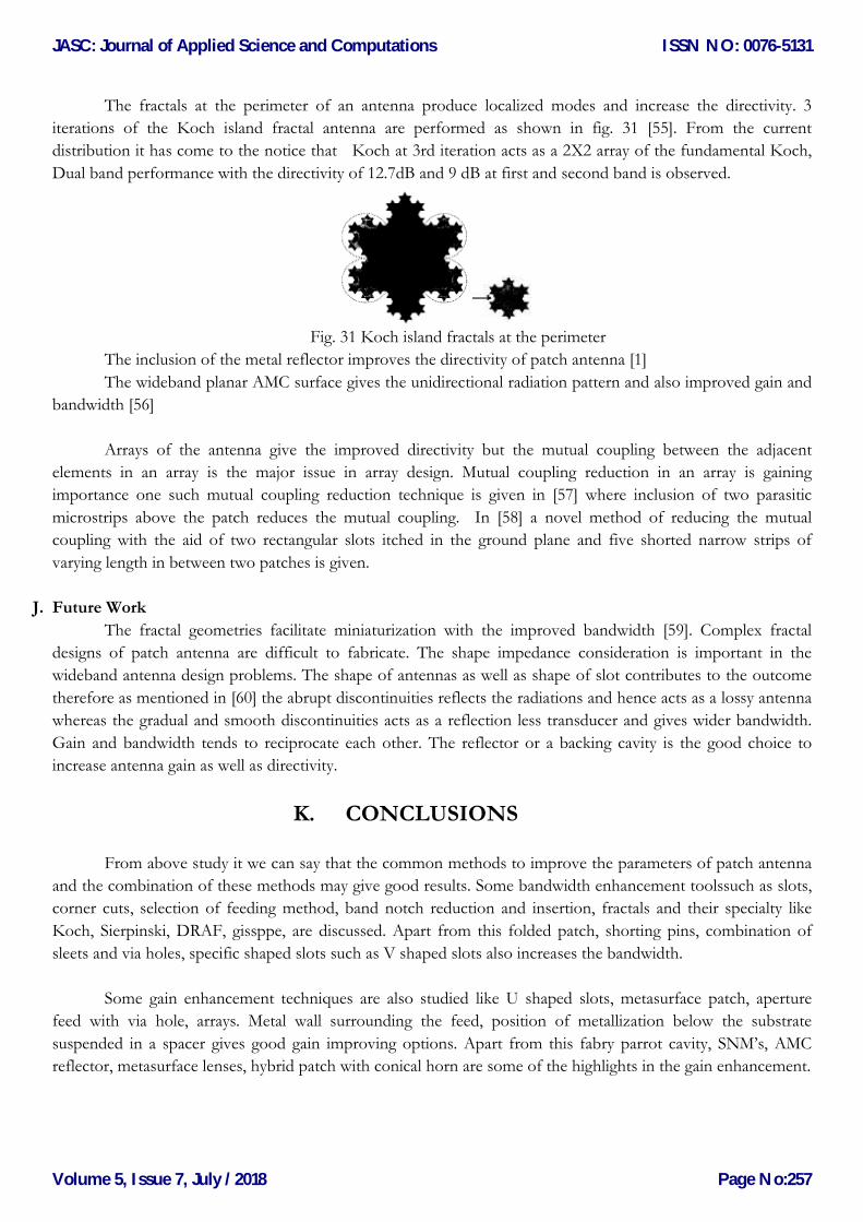
The fractals at the perimeter of an antenna produce localized modes and increase the directivity. 3
iterations of the Koch island fractal antenna are performed as shown in fig. 31 [55]. From the current
distribution it has come to the notice that Koch at 3rd iteration acts as a 2X2 array of the fundamental Koch,
Dual band performance with the directivity of 12.7dB and 9 dB at first and second band is observed.
Fig. 31 Koch island fractals at the perimeter
The inclusion of the metal reflector improves the directivity of patch antenna [1]
The wideband planar AMC surface gives the unidirectional radiation pattern and also improved gain and
bandwidth [56]
Arrays of the antenna give the improved directivity but the mutual coupling between the adjacent
elements in an array is the major issue in array design. Mutual coupling reduction in an array is gaining
importance one such mutual coupling reduction technique is given in [57] where inclusion of two parasitic
microstrips above the patch reduces the mutual coupling. In [58] a novel method of reducing the mutual
coupling with the aid of two rectangular slots itched in the ground plane and five shorted narrow strips of
varying length in between two patches is given.
J. Future Work
The fractal geometries facilitate miniaturization with the improved bandwidth [59]. Complex fractal
designs of patch antenna are difficult to fabricate. The shape impedance consideration is important in the
wideband antenna design problems. The shape of antennas as well as shape of slot contributes to the outcome
therefore as mentioned in [60] the abrupt discontinuities reflects the radiations and hence acts as a lossy antenna
whereas the gradual and smooth discontinuities acts as a reflection less transducer and gives wider bandwidth.
Gain and bandwidth tends to reciprocate each other. The reflector or a backing cavity is the good choice to
increase antenna gain as well as directivity.
K. CONCLUSIONS
From above study it we can say that the common methods to improve the parameters of patch antenna
and the combination of these methods may give good results. Some bandwidth enhancement toolssuch as slots,
corner cuts, selection of feeding method, band notch reduction and insertion, fractals and their specialty like
Koch, Sierpinski, DRAF, gissppe, are discussed. Apart from this folded patch, shorting pins, combination of
sleets and via holes, specific shaped slots such as V shaped slots also increases the bandwidth.
Some gain enhancement techniques are also studied like U shaped slots, metasurface patch, aperture
feed with via hole, arrays. Metal wall surrounding the feed, position of metallization below the substrate
suspended in a spacer gives good gain improving options. Apart from this fabry parrot cavity, SNM’s, AMC
reflector, metasurface lenses, hybrid patch with conical horn are some of the highlights in the gain enhancement.
JASC: Journal of Applied Science and Computations
Volume 5, Issue 7, July /2018
ISSN NO: 0076-5131
Page No:257
Page 17
Directivity can be improved with μ-negative matamaterials, stacking and the combinations if choke,
parasitic patch and coupled feed with via hole also give better directivity. Metal reflector, AMC surface, arrays
and reduction of mutual coupling also offers improved directivity.
From the above study we can conclude that the recent studies are focusing on the particular parameter
enhancement like gain, bandwidth and directivity etc. while improving one parameter other parameters get
affected. Attention should be given on the minute structural parameters to find the scope for improvement.
Some gaps in the research such as when shorting pin is used we must observe for which radius we can get good
results. When fractals are used we can iterate the fractals for smooth discontinuities instead of sharp ones. If
fractals are to be implemented we must watch up to what iteration the geometry performance is improving or
the maximum number of iterations must be noticed. Insertion of via holes in the patch antenna enfluence
coupling between layers in the stacked geometry. Proper feeding methods and its location plays an important
role. Therefore proper combinations of above mentioned methods may give better performance than existing
ones and can fill the gaps in the existing research.
REFERENCES
[1] Xi-Wang Dai, Xiao-Yu Zhou, Guo-Qing Luo, “Wideband directional antenna system with different polarizations for wireless communication
system”, Int. J. Electron. Commun. (AEÜ) 75 (2017) 119–123.
[2] Sapna Verma, J.A. Ansari, “Analysis of U-slot loaded truncated corner rectangular microstrip patch antenna for broadband operation” Int. J.
Electron. Commun. (AEÜ) 69 (2015) 1483–1488.
[3] Kaushik Mandala, Partha Pratim Sarkar, “A compact low profile wideband U-shape antenna with slotted circular ground plane” Int. J.
Electron. Commun. (AEÜ) 70 (2016) 336–340.
[4] Alaknanda Kunwar a, Anil Kumar Gautam b, Karumudi Rambabu, “Design of a compact U-shaped slot triple band antenna for WLAN/
WiMAX applications”, Int. J. Electron. Commun. (AEÜ) 71 (2017) 82–88.
[5] Pratap N. Shinde, Jayashree P. Shinde, “Design of compact pentagonal slot antenna with bandwidth enhancement for multiband wireless
applications” Int. J. Electron. Commun. (AEÜ) 69 (2015) 1489–1494.
[6] Mohammad Alibakhshikenari , Ernesto Limiti , Mohammad Naser-Moghadasi , Bal S. Virdee , R.A. Sadeghzadeh , “A new wideband
planar antenna with band-notch functionality at GPS, Bluetooth and WiFi bands for integration in portable wireless systems”, Int. J. Electron.
Commun. (AEÜ) 72 (2017) 79–85 .
[7] Nagendra Kushwaha a, Raj Kumar “Design of a wideband high gain antenna using FSS for circularly polarized applications”. Int. J. Electron.
Commun. (AEÜ) 70 (2016) 1156–1163.
[8] Homayoon Orazi , Hadi Soleiman, “Miniaturisation of UWB triangular slot antenna by the use of DRAF”, IET Microw. Antennas
Propag., 2017, Vol. 11 Iss. 4, pp. 450-456.
[9] Ziyang Wang, Jinhai Liu, Yingzeng Yin, “Triple band-notched UWB antenna using novel asymmetrical resonators”, Int. J. Electron.
Commun. (AEÜ) 70 (2016) 1630–1636.
[10] Sivaranjan Goswami a, Kumaresh Sarmah a,b, Angana Sarma a,b, Kandarpa Kumar Sarma a, Sunandan Baruah, “Design of a CSRR
based compact microstrip antenna for image rejection in RF down-converter based WLAN receivers”, Int. J. Electron. Commun. (AEÜ) 74
(2017) 128–134.
[11] Shobhit Saxena a, Binod K. Kanaujia b,⇑, Santanu Dwari a, Sachin Kumar c, Rahul Tiwari, “A compact microstrip fed dual polarised
multiband antenna for IEEE 802.11 a/b/g/n/ac/ax applications”, Int. J. Electron. Commun. (AEÜ) 72 (2017) 95–103
[12] Naizhi Wanga, Yue Gao b, Qingsheng Zeng c, “Compact wideband omnidirectional UHF antenna for TV white space cognitive radio
application”, Int. J. Electron. Commun. (AEÜ) 74 (2017) 158–162
[13]Furat Abayaje, Pascal Febvre, “A customized reduced size Antipodal Vivaldi Antenna used in WirelessBaseband Transmission for short-
range communication”, Int. J. Electron. Commun. (AEÜ) 70 (2016) 1684–1691.
[14] Chao Sun, Huili Zheng, and Ying Liu. “Analysis and Design of a Low-Cost Dual-Band Compact Circularly Polarized Antenna for GPS
Application”. IEEE Transactions on Antennas and Propagation, Vol. 64, No. 1, January 2016, 365.
JASC: Journal of Applied Science and Computations
Volume 5, Issue 7, July /2018
ISSN NO: 0076-5131
Page No:258
Page 18
[15] Anil K. Gautama, Aditi Bishta, Binod Kr Kanaujia “A wideband antenna with defected ground plane for WLAN/WiMAX Applications”
Int. J. Electron. Commun. (AEÜ) 70 (2016) 354–358.
[16] Maryam Majidzadeh, Changiz Ghobadi, Javad Nourinia “Novel single layer reconfigurable frequency selective surface with UWB and multi-
band modes of operation”, Int. J. Electron. Commun. (AEÜ) 70 (2016) 151–161.
[17] Rahul Yadav , Piyush N. Patel, “EBG-inspired reconfigurable patch antenna for frequency diversity application”, Int. J. Electron. Commun.
(AEÜ) 76 (2017) 52–59.
[18] Maryam Rahimi a, Mahshid Maleki a, Marjan Soltani a, Afsaneh Saee Arezomand b, Ferdows B. Zarrabi “Wide band SRR-inspired slot
antenna with circular polarization for wireless application”, Int. J. Electron. Commun. (AEÜ) 70 (2016) 1199–1204.
[19] Samson Daniel R., Pandeeswari R., Raghavan S., “Multiband monopole antenna loaded with Complementary Split Ring Resonator and C-
shaped slots”, Int. J. Electron. Commun. (AEÜ) 75 (2017) 8–14.
[20] Nand Kishore , Arun Prakash , Vijay Shanker Tripathi, “A reconfigurable ultra wide band antenna with defected ground structure for ITS
application”, Int. J. Electron. Commun. (AEÜ) 72 (2017) 210–215.
[21] Bappadittya Roy a, A. Bhattacharya a, S.K. Chowdhury b, A.K. Bhattacharjee, “Wideband Snowflake slot antenna using Koch iteration
technique for wireless and C-band applications” Int. J. Electron. Commun. (AEÜ) 70 (2016) 1467–1472.
[22]Hossein Rajabloo , Vahid Amiri Kooshki, Homayoon Oraizi, “Compact microstrip fractal Koch slot antenna with ELC coupling load for
triple band application”, Int. J. Electron. Commun. (AEÜ) 73 (2017) 144–149.
[23] Sarthak Singhal , Amit Kumar Singh “CPW-fed hexagonal Sierpinski super wideband fractal antenna” IET Microw. Antennas Propag.,
2016, Vol. 10, Iss. 15, pp. 1701–1707 ISSN 1751-8725.
[24] Sarthak Singhal , Amit Kumar Singh “CPW-fed octagonal super-wideband fractal Antenna with defected ground structure” IET Microw.
Antennas Propag., 2017, Vol. 11 Iss. 3, pp. 370-377.
[25] Bikash Ranjan Behera, “Sierpinski Bow-Tie antenna with genetic algorithm”, Engineering Science and Technology, an International Journal
20 (2017) 775–782.
[26] Homayoon Oraizi, Amrollah Amini, Mehdi Karimi Mehr, “Design of miniaturized UWB log-periodic end-fire antenna using several fractals
with WLAN band-rejection”, IET Microw. Antennas Propag., 2017, Vol. 11, Iss. 2, pp. 193–202 & the Institution of Engineering and
Technology 2016
[27] Neng-Wu Liu et. al. “A Differential-Fed Microstrip Patch Antenna With Bandwidth Enhancement Under Operation of TM10 and TM30
Modes” IEEE Transactions on Antennas and Propagation, Vol. 65, NO. 4, April 2017. [17]. Khushboo Tiwari and Dhaval Pujara.
“Multilayer Slotted Microstrip Antenna for Wi-Fi Application”. 978-1-4799-7815-1/15/$31.00 ©2015 IEEE, 1932, AP-S 2015.
[28] Khushboo Tiwari and Dhaval Pujara. “Multilayer Slotted Microstrip Antenna for Wi-Fi Application”. 978-1-4799-7815-1/15/$31.00
©2015 IEEE, 1932, AP-S 2015.
[29] HangWong et al. “Bandwidth Enhancement of a Monopolar Patch Antenna With V-Shaped Slot for Car-to-Car and WLAN
Communications” IEEE Transactions on Vehicular Technology, Vol. 65, No. 3, March 2016.
[30] J. H. Liu, Q. Xue, H. Wong, and H. W. Lai, “Design and analysis of a low-profile and broadband microstrip monopolar patch antenna,”
IEEE Trans. Antennas Propag., vol. 61, no. 1, pp. 11–18, Jan. 2013.
[31] W. Chen, K. F. Lee, and J. S. Dahele, “Theoretical and experimental studies of the resonant frequencies of the equilateral triangular microstrip
antenna,” IEEE Trans. Antennas Propag., vol. 40, no. 10, pp. 1253–1256, Oct. 1992.
[32] J. S. Row and Y. Y. Liou, “Broadband short-circuited triangular patch antenna,” IEEE Trans. Antennas Propag., vol. 54, no. 7, pp.
2137–2141, Jul. 2006.
[33] M. Rostamzadeh, S. Mohamadi, J. Nourinia, C. Ghobadi, and M. Ojaroudi, “Square monopole antenna for UWB applications with novel
rod-shaped parasitic structures and novel V-shaped slots in the ground plane,” IEEE Antennas Wireless Propag. Lett., vol. 11, pp. 446–449,
2012.
[34] Hossein Malekpoor,Shahrokh Jam, “Analysis on bandwidth enhancement of compact probe fed patch antenna with equivalent transmission line
model”, IET Microw. Antenna Propag., 2015, Vol. 9, Iss 11, pp. 1136-1143.
[35] Donovan E. Brocker, Zhi Hao Jiang, Micah D. Gregory, and Douglas H. Werner “Miniaturized Dual-Band Folded Patch Antenna With
Independent Band Control Utilizing an Interdigitated Slot Loadin”, IEEE Transactions on Antennas and Propagation, Vol. 65, No. 1,
January 2017.
[36] Sasmita Pahadsingh, Sudhakar Sahu, “Planar UWB integrated with multi narrowband cylindrical dielectric resonator antenna for cognitive
radio application”, Int. J. Electron. Commun. (AEÜ) 74 (2017) 150–157
[37] Huiqing Zhai, Qiqiang Gao, Changhong Liang, Rongdao Yu, and Sheng Liu “A Dual-Band High-Gain Base-Station Antenna for
WLAN and WiMAX Applications” A Dual-Band High-Gain Base-Station Antenna for WLAN and WiMAX Applications
[38] Y. M. Pan, P. F. Hu, X. Y. Zhang, and S. Y. Zheng “A Low-Profile High-Gain andWideband Filtering Antenna with Metasurface”
IEEE Transactions on Antennas and Propagation, Vol. 64, No. 5, May 2016.
JASC: Journal of Applied Science and Computations
Volume 5, Issue 7, July /2018
ISSN NO: 0076-5131
Page No:259
Page 19
[39] Wenwen Yang, Jianyi Zhou, Zhiqiang Yu, and Linsheng Li, “Bandwidth- and Gain-Enhanced Circularly Polarized Antenna Array Using
Sequential Phase Feed” IEEE Antennas and Wireless Propagation Letters, Vol. 13, 2014.
[40] Babak Honarbakhsh “High-gain low-cost microstrip antennas and arrays based on FR4 epoxy” Int. J. Electron. Commun. (AEÜ) 75
(2017) 1–7.
[41] H. Moghadas, M. Daneshmand and P. Mousavi “Dual-band high-gain resonant cavity antenna with orthogonal polarisation using slotted patch
partially reflective superstrate” Electronics Letters 19th July 2012 Vol. 48 No. 15
[42] Zahra Mousavi Razi, Pejman Rezaei, Arash Valizade “A novel design of Fabry-Perot antenna using metamaterial superstrate for gain and
bandwidth enhancement” Int. J. Electron. Commun. (AEÜ) 69 (2015) 1525–1532.
[43] Xiang-Jun Gao, Tong Cai , Li Zhu “Enhancement of gain and directivity for microstrip antenna using negative permeability metamaterial” Int.
J. Electron. Commun. (AEÜ) 70 (2016) 880–885.
[44] Rengasamy Rajkumar, Kommuri Usha Kiran, “A compact metamaterial multiband antenna for WLAN/WiMAX/ITU band
applications”, Int. J. Electron. Commun. (AEÜ) 70 (2016) 599–604
[45] Pooja Prakash, Mahesh P. Abegaonkar, A. Basu, and Shiban K. Koul, “Gain Enhancement of a CPW-Fed Monopole Antenna Using
Polarization-Insensitive AMC Structure” IEEE Antennas and Wireless Propagation Letters, Vol. 12, 2013
[46] Hailiang Zhu, Sing Wai Cheung, and Tung Ip Yuk “Enhancing Antenna Boresight Gain Using a Small Metasurface Lens” IEEE
Antennas & Propagation Magazine February 2016.
[47] Yong Zhi Cheng a,b, Ji Jin a, Wen Long Li b, Jun Feng Chen c, Bin Wanga, Rong Zhou Gong, “Indefinite-permeability metamaterial lens
with finite size for miniaturized wireless power transfer system”, Int. J. Electron. Commun. (AEÜ) 70 (2016) 1282–1287.
[48] Xiu Yin Zhang, Wen Duan, and Yong-Mei Pan “High-Gain Filtering Patch Antenna without Extra Circuit” IEEE Transactions on
Antennas and Propagation, Vol. 63, No. 12, December 2015.
[49] Ayman Elboushi and Abdelrazik Sebak, “High-Gain Hybrid Microstrip/Conical Horn Antenna for MMW Applications”, IEEE
Antennas and Wireless Propagation Letters, Vol. 11, 2012.
[50] Cheng Huang, Wenbo Pan, Xiaoliang Ma, and Xiangang Luo “A Frequency Reconfigurable Directive Antenna with Wideband Low-RCS
Property” IEEE Transactions on Antennas and Propagation, Vol. 64, No. 3, March 2016.
[51] Hamidreza Memarzadeh-Tehran a, Ramesh Abhari b, Mohsen Niayesh, “A cavity-backed antenna loaded with complimentary split ring
resonators”, Int. J. Electron. Commun. (AEÜ) 70 (2016) 928–935.
[52] Sasan Ahdi Rezaeieh, Marco A. Antoniades and Amin M. Abbosh, “Compact Wideband Loop Antenna Partially Loaded With Mu-
Negative Metamaterial Unit Cells for Directivity Enhancement” IEEE Antennas and Wireless Propagation Letters, Vol. 15, 2016.
[53] Gopi Ram, Durbadal Mandal, Rajib Kar, Sakti Prasad Ghoshal, “Directivity maximization and optimal far-field pattern of time modulated
linear antenna arrays using evolutionary algorithms”, Int. J. Electron. Commun. (AEÜ) 69 (2015) 1800–1809.
[54] Insu Yeom, Jin Myung Kim and Chang Won Jung, “Dual-band slot-coupled patch antenna with broad bandwidth and high directivity for
WLAN access point” Electronics Letters 8th May 2014 Vol. 50 No. 10 pp. 726–728.
[55] C. Borja, G. Font, S. Blanch and J. Romeu, “High directivity fractal boundary microstrip patch antenna”, Electronics Letters 27th April 2000
Vol. 36 No. 9.
[56] Hossein Malekpoor and Shahrokh Jam, “Improved Radiation Performance of Low Profile Printed Slot Antenna Using Wideband Planar
AMC Surface” IEEE Transactions on Antennas and Propagation, Vol. 64, No. 11, November 2016
[57] Xu-bao Sun a, Mao-yong Cao, “Mutual coupling reduction in an antenna array by using two parasitic microstrips”, Int. J. Electron. Commun.
(AEÜ) 74 (2017) 1–4.
[58] Ahmad Emadeddin, Saeideh Shad, Zahra Rahimian, H.R. Hassani, “High mutual coupling reduction between microstrip patch antennas
using novel structure”, Int. J. Electron. Commun. (AEÜ) 71 (2017) 152–156.
[59] “Antenna Theory Analysis and Design”, Constantine A. Balanis, Third Edition, ISBN: 0-471-66782-X, A John Wiley & Sons, Inc.,
Publication.
[60] John D. Kraus, “Antennas”, Second Edition, Tata McGrow-Hill 1997.
JASC: Journal of Applied Science and Computations
Volume 5, Issue 7, July /2018
ISSN NO: 0076-5131
Page No:260