Page 1
University of South FloridaScholar Commons
Graduate Theses and Dissertations Graduate School
5-1-2014
A Synthesis Approach Of TRP-Like PrimaryAmine Peptoid Side Chains Used In Cyclic Beta-Hairpin - Like ScaffoldsJosanne-Dee WoodroffeUniversity of South Florida, [email protected]
Follow this and additional works at: https://scholarcommons.usf.edu/etd
Part of the Chemistry Commons
This Thesis is brought to you for free and open access by the Graduate School at Scholar Commons. It has been accepted for inclusion in GraduateTheses and Dissertations by an authorized administrator of Scholar Commons. For more information, please contact [email protected] .
Scholar Commons CitationWoodroffe, Josanne-Dee, "A Synthesis Approach Of TRP-Like Primary Amine Peptoid Side Chains Used In Cyclic Beta-Hairpin - LikeScaffolds" (2014). Graduate Theses and Dissertations.https://scholarcommons.usf.edu/etd/5156
Page 2
A Synthesis Approach Of TRP-Like Primary Amine Peptoid Side Chains Used In
Cyclic β-Hairpin – Like Scaffolds
By
Josanne-Dee Woodroffe
A Thesis submitted in partial fulfillment
of the requirements for the degree of
Master of Science in Chemistry
Department of Chemistry
College of Arts and Sciences
University of South Florida
Major Professor: Mark McLaughlin, Ph.D.
Roman Manetsch, Ph.D.
Wayne C. Guida, Ph. D.
Lori Hazlehurst, Ph. D.
Date of Approval:
March 17, 2014
Keywords: Peptides, Fischer Indoles, Sub-monomer Synthesis Method, MTI-101
Copyright © 2013, Josanne-Dee Woodroffe
Page 3
DEDICATION
“This thesis is dedicated to my loving daughter who has always been encouraging towards me
accomplishing my goal. You will forever be my rock!”
Page 4
ACKNOWLEDGMENTS
First and foremost, I would like to thank my mother, who has given me a strong driving force to always
achieve for excellence; you have always taught me that my best can be better, and even though in my
childhood I never understood it, as an adult pursing all my life goals I thank you for that. I love you, and
thank you for instilling in me to always be a strong independent woman.
To my lab mates, Hyun Kil, Yi Liang and Michael Doligalski, you all have been helpful and supportive in
me accomplishing my projects. I know these past months have been challenging to work in the dark,
thank you for always being respectful. To Tarah Word, Tamalia Juilen and Kia Williams, you have been
my sisters in this program. Thank you for always being there for “Joey” and me as a support system. To
my major professor, Professor Mark McLaughlin, for taking a chance on me and always being very
flexible and understanding to my personal situations where my daughter is concern. It is because of you I
am receiving this degree and will obtain my Ph.D. Because of your mentoring, encouragement, and your
advice I am a better chemist. To my remaining committee members, Dr. Roman Manetsch, Professor
Wayne Guida and Dr. Lori Hazlehurst, thank you for being accommodating when needed and making it
possible to achieve my goal.
To Dexter Mason, my best friend and loving boyfriend, you have been extremely supportive and helpful
during the writing process of this thesis. Thank you for your patience and for the sacrifices you made to
ensure I completed this task. And lastly, to my daughter, Jolene-Marie Woodroffe, even at such a young
age you have always shown great maturity and understanding in me going back to school. There aren’t
enough words to describe how proud I am of you. You are truly God sent and my pillar of strength. I
love you!
Page 5
i
TABLE OF CONTENTS
List of Figures……………………………………………………………………………………………….i
List of Tables……………………………………………………………………………………………….ii
Abstract…………………………………………………………………………………………………….iii
Chapter One: Introduction and Background…………………………………………….……………….....1
1.1 Peptoids…………………………………………………………………………………….….1
1.2 The Submonomer Approach………………………………………………………………….2
1.3 Advantages of Peptoids……………………………………………………………….………3
1.4 Purpose/Goal……………………………………………………………………………….….3
Chapter Two: Methodology…………………………………………………………………….….……….7
2.1 Preparation and Analysis of Samples……………….………………………………..………..7
2.1.1 Plate Development……………………………………………………….…….…8
2.2 Thin-Layer Chromatography…………………………………………………………..……...9
2.3 Mass Spectroscopy…………………………………………………………………….…..….9
2.3.1 Liquid Chromatography – Mass Spectroscopy…………………………….…...10
2.4 Nuclear Magnetic Resonance………………………………………………………………..13
2.4.1. Magnetic Properties of Nuclei…………………………………………………….14
2.4.2 Excitation of Spin 1/2 Nuclei………………………………………………………14
2.5 Proton NMR (1H)…………………………………………………………………………..…15
2.5.1 Spin Coupling……………………………………………………………………...15
2.5.1.1 Splitting Pattern for a Doublet…………………………………………………...16
2.5.1.2 Splitting Pattern for a Triplet ……………………………………………………17
2.5.1.3 Splitting Pattern for a Quartet …………………………………………………...18
2.6 Interpretation of a Predicted 1H NMR ……………………………………………………….19
2.7 Carbon-13 NMR (13
C)…………………………………………………………………..……20
2.8 Interpretation of a Predicted 13C NMR………………………………………………….…..20
Chapter Three: Experimental Section…………………………………………………………………….26
Chapter Four: Discussion…………………………………………………………………………….……39
Chapter Five: Conclusion…………………………………………………………………………………47
References………………………………………………………………………………………………...50
Appendices………………………………………………………………………………………………...51
Supporting Data…………………………………………………………………………………………...54
Page 6
ii
LIST OF TABLES
Table 1: List of Chemicals used in the synthesis of the trp-like primary amines……….……..…..….28
Table 2: Fischer Indole Synthesis from 3,4-dihydro-2Hpyran and Phenyl Hydrazine.HCl
in 6% H2SO4 in NMP………..………………….……………………………………...…...52
Page 7
iii
LIST OF FIGURES
Figure 1.1.Structure of a fragment of a Peptide and Peptoid. The amide proton in the
Peptide has been replace by the R group side chains in the peptoid………………………....1
Figure 1.2. An Overall Two-Step Scheme representing the Peptoid Sub-monomer Synthesis
Method………………………………………………………….……………………….……2
Figure 1.3. A cyclic β-hairpin-like scaffold with six variable peptoid side chains, R1-R6, 6
glycines, and 1 β-turn promoter with anchorage to the resin……………………….…..…….4
Figure 1.4. The structure of MTI-101, a cyclic β-hairpin peptide that is being developed for
its significant in vivo activity against multiple myeloma……………………………………4
Figure 1.5. Primary amines with R group peptoid side chains that roughly simulate natural
amino acid side chains………………………………………………………………………..5
Figure 1.6. Primary amines with R group peptoid side chains that roughly simulate natural
amino acid side chains………………………………………………………………………..6
Figure 1.7. An outline of a cycloaddition of an azide and acetylene group (Click Reaction)……...….….6
Figure 1.8. Proposed Cyclic β-hairpin-like scaffold…………………………………………………........6
Figure 2.1. Development of a TLC plate showing the different Rf values of the starting
Material and the product formed in a reaction……………………………………….……….8
Figure 2.2. Internal view of the setup of Liquid Chromatography- Mass Spectrometer. The
LC/MS is composed of three basic components – Spray chamber, Quadrupole
mass separator and Detector………………………………………………………………..10
Figure 2.3. Electronspray Ionization – the “Columbic explosion” of the sample’s molecules……....….11
Figure 2.4. Internal structure of the four cylindrical rods in the quadrupole mass separator
showing the excited ions……………………………………………………………..….….12
Figure 2.5. Diagram of Gas chromatography column outlet and quadrupole mass separator…..….....…12
Figure 2.6. Magnetic dipole generated from the charge of a proton spinning……………………...……13
Figure 2.7. Excitation of Spin ½ Nuclei in an external magnetic field of magnitude B0……….….….…14
Page 8
iv
Figure 2.8. Splitting pattern for a doublet showing 1:1 intensity of the peaks…………………………..16
Figure 2.9. Splitting pattern for a triplet showing 1:2:1 intensity of the peaks…………………...….….17
Figure 2.10. Splitting pattern for a quartet showing 1:3:3:1 intensity of the peaks……………....………18
Figure 2.11. Predicted 1H NMR of 3-(1H-indol-3-yl)propan-1-ol, a precursor to one of the
primary amines……………………………………………………….……………….…....19
Figure 2.12. Predicted 13
C NMR of 3-(1H-indol-3-yl)propan-1-ol, a precursor to one of the
primary amines synthesized…………………………………………………………...…..21
Scheme 1: A general strategy to synthesize a library of R-substituted, CBZ-protected
primary amines…………………………………………………………………….….....…25
Figure 4.1. Proposed two step detailed mechanism of Fischer Indole Synthesis with
highlighted side product formed as an precursor to the desired Indole………….......…….40
Figure 4.2. Oxidation of Indole ring showing resonance of the nitrogen lone pairs of
electrons in the amide bond…………………………………………………………………42
Figure 4.3. Dehydration of the OH group…………………………………………………………….….43
Figure 4.4. Proposed three step detailed mechanism for the Mitsunobu reaction……………………….44
Figure 4.5. Proposed mechanism for Cbz Protection of the secondary amine…………………………..45
Figure 4.6. Proposed mechanism for the Deprotection of the phthalimide group……………………….46
Figure 5.1. Fischer Indoles synthesized from hydrazines with electron donating groups……………….47
Figure 5.2. Fischer Indole synthesized from 2,3-dihydrofuran………………………………………….48
Figure 5.3. Proposed cyclic β-hairpin-like scaffold with trp-like side chain in the R2 position…………48
Figure 5.4. Proposed Cyclic β-hairpin-like scaffold with trp-like side chain in the R4 position…….…..49
Scheme 2: Proposed two step detailed mechanism of Fischer Indole Synthesis with
highlighted side product formed as an precursor to the desired Indole…………….……….53
Page 9
v
ABSTRACT
In recent studies it was reported that the D-amino acid containing peptide HYD1 was used in the
treatment of necrotic cell death in multiple myeloma cell lines and showed promising biological activity
and in vivo activity. It was meaningful to explore strategies for increasing the therapeutic efficacy of
HYD1, a linear peptide. These efforts led to the development of MT1-101 (cyclized peptidomimetics), a
lead compound that showed increased in vitro activity and in vivo activity. MTI-101 was found to bind
the cell adhesion molecule CD44 and induce programmed necrosis in myeloma cell lines. It was
important to improve on the binding efficiency of the MTI-101 to this target and explore more cost
effective ways to synthesize this peptide. This lead to developing Cyclic β-hairpin-like peptoid scaffolds,
which introduced diverse families of random peptoid-body libraries that will be screened to find small
stable scaffolds that compete with and can replace antibodies as cell-surface targeting reagents. The
synthesis of peptoids on solid-support can be more cost effective and a large library can be developed
using a diverse library of primary amines. This initiated this thesis project to develop a generalized
scheme for the synthesis of TRP-like primary amine peptoid side chains used in the cyclic β-hairpin –
Like scaffolds.
Page 10
1
CHAPTER ONE:
Introduction and Background
1.1. Peptoids
Peptoids represent a new class of polymers that are not found in nature, but are synthetically accessible
and have shown to possess significant biological activity and proteolytic stability.1 Peptoids, first
invented by Reyna J. Simon, Paul Bartlett and Daniel V. Santi to mimic protein/peptide products, was
used as drug discovery scaffolds in finding protease-stable small molecule drugs. Peptoids, also known
as oligo-N- substituted glycines, are a class of small protein-like chains whose side chains replaced the
amide proton of the peptide backbone, rather than attached to the α-carbons as they are in amino acids.
Figure 1.1. Structure of a fragment of a Peptide and Peptoid. The amide proton in the peptide has been replaced by the
R group side chains in the peptoid.
This structure modification limits peptoids from having a secondary structure found in peptides/protein
and has resulted in attempts to develop peptoids with well-defined secondary structures conducted by
Ronald Zuckermann. Subsequently, Zuckermann originally created a submonomer protocol that inserts
each residue in two steps: Acylation and Displacement. In the acylation step a haloacetic acid, typically
Page 11
2
bromoacetic acid, is activated by diisopropylcarbodiimide (DIC) and subsequently reacts with the amine
of the previous residue. In the nucleophilic displacement step, a classical SN2 reaction, an amine
displaces the halide to form the N-substituted glycine residue. 2
Figure 1.2. An Overall Two-Step Scheme representing the Peptoid Sub-monomer Synthesis Method. Step 1: Acylation of
bromoacetic acid. Step two: Nucleophilic displacement of Br by the desired primary amine. The sphere represents the Resin
(solid support).
1.2. The Submonomer Approach
The submonomer approach allows the use of any commercially available or synthetically accessible
amines which give the peptoid-body scaffold great potential to discover high affinity targeting ligands.
Originally, the synthesis of oligomeric N-substituted glycines (NSG) is analogous to the standard solid-
phase methods for peptide synthesis. The carboxylate of the N-Fmoc-protected NSGs, which is side
chain protected, is activated and then coupled to the secondary amino group of the resin-bound peptoid
chain. The Fmoc group is then removed under basic conditions and followed by addition of the next
Fmoc-protected monomer. The disadvantage of this approach is the preparation of suitable quantities of a
diverse set of protected N-substituted glycines.1 In the submonomer method, outlined in Scheme 1 above,
the need for N-protected monomers has been eliminated and only the reactive side chains functionalities
are protected. The solid-phase assembly of each monomer, in an alternating haloacetic acid-primary
amine pattern, follows the same direction as in the original method, in the carboxy to amino direction.
Page 12
3
1.3. Advantages of Peptoids
Peptoids are completely resistant to proteolysis, and are therefore advantageous for therapeutic
applications where proteolysis is a major issue. The secondary structure in peptoids does not involve
hydrogen bonding, and thus it is not typically denatured by chemical denaturants such as urea,
temperature or solvent. Peptoids have been developed as candidates for a range of different biomedical
applications, including antimicrobial agents and synthetic lung surfactants.
1.4. Purpose/Goal
It is anticipated that families of large random peptoid-body libraries will be screened to find small stable
scaffolds that compete with and can replace antibodies as cell-surface targeting reagents.4 In conjunction
with having too small of a molecular weight to elicit much, if any, of an immune response, these scaffolds
can be modified to specifically fit the needs of the targeted agent and thus improve on clearance times
compared to antibodies and hence decrease toxicities. The proposed cyclic β-hairpin-like scaffold (figure
1.3) that will be synthesized will be much more rigid than standard peptoids and much less polar that
cyclic peptides due to the nature of all the exo amide hydrogens being changed to R-groups in the
peptoids; polarity is dependent on the functional groups of the peptoid side chains. This may improve
cell-permeability and oral bioavailability. The focus of this research thesis is to develop a generalized
synthetic scheme to build a library of primary amines that will be used in synthesizing standard peptoid
One-Bead One-Compound (OBOC) libraries with hit rates for libraries of 1-2/105 per target. These
primary amines give diversity to the peptoid side chains and are intentionally selected to be flexible to
compensate for the rigidity of the core structure of the cyclic β-hairpin-like peptoid.
Page 13
4
Figure 1.3. A cyclic β-hairpin-like scaffold with six variable peptoid side chains, R1-R6, 6 glycines, and 1 β-turn
promoter with anchorage to the resin.4
The six variable peptoid side chains, R1-R6, roughly simulate natural amino side chains to intentionally
add greater side chain flexibility among the polar side chains since they would often have specific
hydrogen bonding constraints. The peptoid side chains are primary amines which are specifically
position in the R1-R6 position based on previous hits from the most potent cyclic analog MTI-101 shown
in figure 1.4. MTI-101 is a lead candidate, developed by Modulation Therapeutics Inc., which binds the
cell adhesion molecule CD44 and induces programmed necrosis in myeloma cell lines and demonstrates
vigorous anti-tumor activity as a single agent. MTI-101 targets alternative cell death pathways critical
for the treatment of refractory disease, unlike standard therapy that typically induces apoptotic cell death.3
Figure 1.4. The structure of MTI-101, a cyclic β-hairpin peptide that is being developed for its significance in vivo
activity against multiple myeloma. The highlighted amino acids positioned from the left to right represent R2, R3, and R4 peptoid
side chains, respectively, on the proposed cyclic β-hairpin-like peptoid, as well as a reverse order of R4, R3, and R2, respectively.4
Page 14
5
The hydrophobic side chains of the cyclic β-hairpin-like peptoid contribute to binding energy when
buried into a hydrophobic cleft, where as the polar side chains strongly contribute to binding specificity
and thus it is reasoned that greater flexibility of the Trp-like side chain is important in the design of a
random screening library.4 Despite it was reported that in MTI-101, the unsubstituted indole in Trp-like
side chain showed more bioactivity than the substituted, it is worthwhile to explore different mono and di-
substituted indoles (figure 1.5) in position R2 and R4 in the cyclic β-hairpin-like peptoid to explore
chemical diversity. The following synthesized primary amines have been characterized.
Figure 1.5. Trp-like primary amines with R group peptoid side chains.
The proposed scheme (scheme 1) used to develop the library of primary amines with a carbon chain
length of three CH2 is expanded to explore a carbon chain length of two CH2 (figure 1.6) as seen in
scheme 2.
Figure 1.6. Primary amines with R group peptoid side chains that roughly simulate natural amino acid side chains.
Based on previous studies it was anticipated that replacing the exo amide protons with R5 and R6 peptoid
side chains may improve on the rigidity of the cyclic β-hairpin-like peptoid. It was proposed to
Page 15
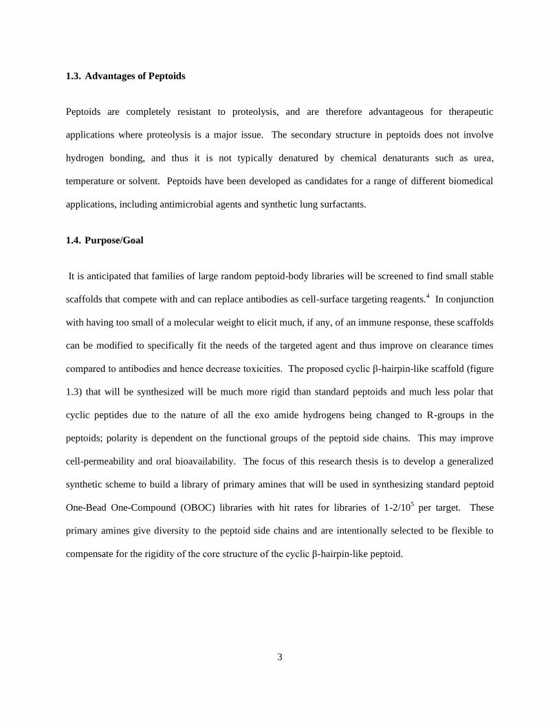
6
synthesize (3-(azidomethyl)phenyl)methanamine 9, and (3-(prop-2-yn-1-yl)phenyl)methanamine 10,
primary amines with an azide and terminal acetylene group, respectively, in the meta position to the
primary amino group on the phenyl ring. The azide and alkyne undergo a cycloaddition reaction
selectively to give a 1,2,3-triazole (figure 1.7).
Figure 1.7. An outline of a cycloaddition of an azide and acetylene group (Click Reaction).
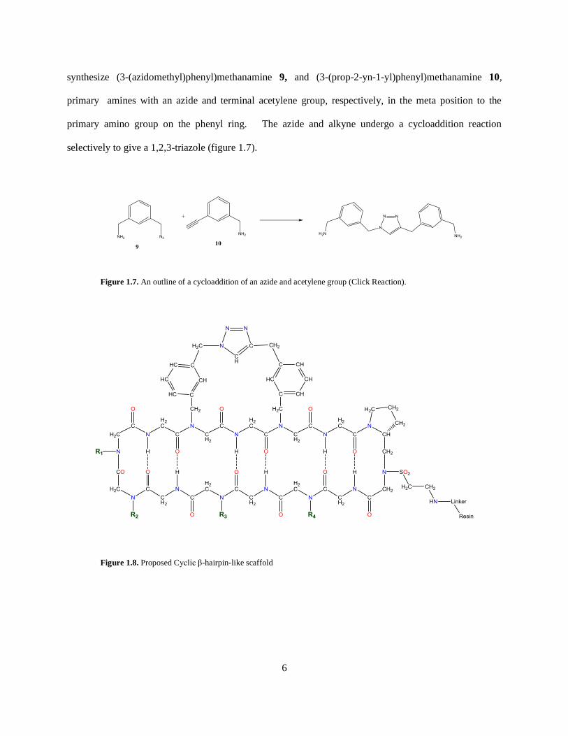
Figure 1.8. Proposed Cyclic β-hairpin-like scaffold
Page 16
7
CHAPTER TWO
Methodology
2.1. Preparation & Analysis of Samples
All samples were analyzed using Liquid Chromatography – Mass spectroscopy (LC/MS) and Nuclear
Magnetic Resonance (NMR). The course of the reactions was monitored by Thin-Layer Chromatography
(TLC) in observing the disappearance of the starting material.
2.2. Thin-Layer Chromatography
Thin-layer chromatography is a cost effective chromatography technique used to separate non-volatile
mixtures. This simple and quick procedure can be used to determine how many components are in a
mixture and to monitor the course of a reaction. This analytical technique comprises of two phases: a
stationary phase, a thin layer of adsorbent material, usually silica gel, aluminium oxide, or cellulose
coating a thin sheet of glass, aluminium foil or plastic; and a mobile phase, a solvent or solvent mixture
(eluent). Once separation is completed individual compounds appear as vertical spots. Each spot has a
Retention Factor (Rf) that represents the distance traveled over to total distance covered by the mobile
phase.
Rf = distance traveled by the compound
distance traveled by the solvent
TLC can be used to identify a compound in a mixture by comparing the Rf of the compound with the Rf of
a known compound. The Rf value can be used to identify compounds due to their uniqueness to each
compound. Rf values and reproducibility can be affected by a number of different factors such as layer
Page 17
8
thickness, moisture on the TLC plate, vessel saturation, temperature, depth of mobile phase, nature of the
TLC plate, sample size, and solvent parameters. These effects normally cause an increase in Rf values.5
2.2.1 Plate development
A horizontal line is drawn 1 cm from the bottom of the plate and three equally spaced dots are
placed along the line that represents the starting material (SM), reaction mixture (RXN) and Co, for both
SM and RXN. After each component has been applied and their solvent evaporates, the plate is placed in
a closed chamber that is saturated with vapors of the developing solvent from the mobile phase. This
eluent slowly rises up the TLC plate by capillary action passing the spots applied to the plate. An
equilibrium is established for each component between the molecules of that component which are
adsorbed on the stationary phase and that which are in solution (mobile phase). Once the mobile phase
has transverse to 0.5 cm from the top, the plate is removed from the chamber and dried.
Figure 2.1. Development of a TLC plate showing the different Rf values of the starting material and the product
formed in a reaction.
In principle, the components differ in solubility and strength of adsorption to the adsorbent based on their
polarity. More non-polar components will be carried further up the plate than polar ones. This in theory
can be used to determine if any starting material is present in the event of monitoring the course of a
reaction as demonstrated in figure 2.1. The Rf of the starting material would be different from that of the
Page 18
9
product and any side products formed. TLC was also used to determine the purity of the compounds
made. The compounds were visible under short-wave UV light using fluorescent plates. An Iodine
chamber containing Iodine and silica gel was used to determine the presence of any “none” UV active
impurities that were stained brown. Ninhydrin staining was also used to detect the presence of the
primary amines
2.3. Mass Spectroscopy
Mass spectroscopy is an analytical technique that measures the mass-to-charge ratio of charged particles
and provides information of the elemental composition and complex mixtures producing a spectrum. The
spectrum can be used to determine masses of particles and, of molecules, isotopic ratios of atoms and
distinguish between them, (for example 35
Cl and 37
Cl and 79
Br and 81
Br). Mass spectroscopy is a simple,
sensitive, and routine measurement that has hundreds of applications. Its application is oriented towards
the separation, general detection and potential identification of chemicals of particular masses in the
presence of other chemicals (i.e., in complex mixtures), for example natural products from natural-
products extracts, and pure substances from mixtures of chemical intermediates.7 The instrumentation
compromises of two major and independent components: Ionization Methods and Ion separation
Methods.6 In the ionization method, chemical compounds are ionized by a bombardment of electrons to
generate charged molecules or fragments of the molecule. The ions are separated according to their mass-
to-charge ratio in an analyzer by electromagnetic fields in the ion separation methods. After detection of
the ions the ion signal is processed based on the number of ions representing each mass/charge “unit”, and
is recorded as a mass spectrum.7
Page 19
10
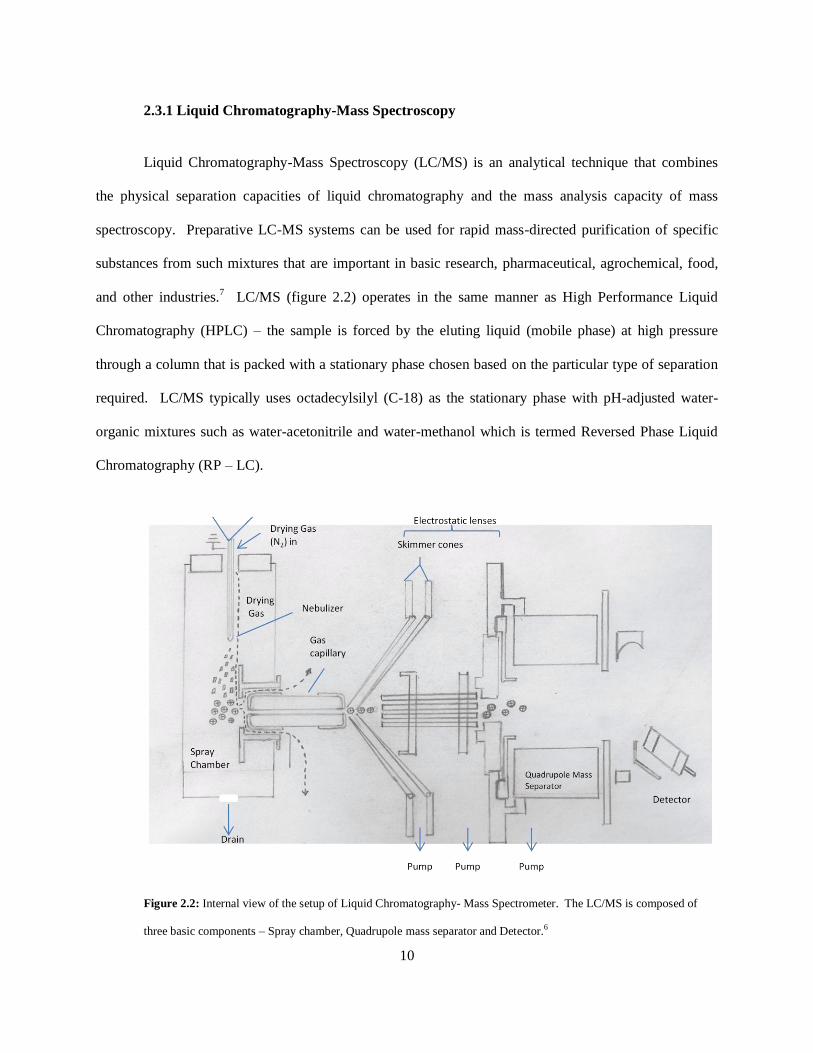
2.3.1 Liquid Chromatography-Mass Spectroscopy
Liquid Chromatography-Mass Spectroscopy (LC/MS) is an analytical technique that combines
the physical separation capacities of liquid chromatography and the mass analysis capacity of mass
spectroscopy. Preparative LC-MS systems can be used for rapid mass-directed purification of specific
substances from such mixtures that are important in basic research, pharmaceutical, agrochemical, food,
and other industries.7 LC/MS (figure 2.2) operates in the same manner as High Performance Liquid
Chromatography (HPLC) – the sample is forced by the eluting liquid (mobile phase) at high pressure
through a column that is packed with a stationary phase chosen based on the particular type of separation
required. LC/MS typically uses octadecylsilyl (C-18) as the stationary phase with pH-adjusted water-
organic mixtures such as water-acetonitrile and water-methanol which is termed Reversed Phase Liquid
Chromatography (RP – LC).
Figure 2.2: Internal view of the setup of Liquid Chromatography- Mass Spectrometer. The LC/MS is composed of
three basic components – Spray chamber, Quadrupole mass separator and Detector.6
Page 20
11
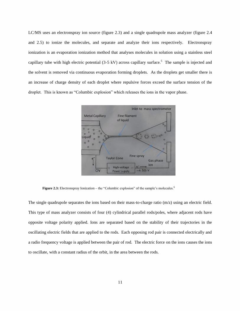
LC/MS uses an electronspray ion source (figure 2.3) and a single quadrupole mass analyzer (figure 2.4
and 2.5) to ionize the molecules, and separate and analyze their ions respectively. Electronspray
ionization is an evaporation ionization method that analyses molecules in solution using a stainless steel
capillary tube with high electric potential (3-5 kV) across capillary surface.5 The sample is injected and
the solvent is removed via continuous evaporation forming droplets. As the droplets get smaller there is
an increase of charge density of each droplet where repulsive forces exceed the surface tension of the
droplet. This is known as “Columbic explosion” which releases the ions in the vapor phase.
Figure 2.3: Electronspray Ionization – the “Columbic explosion” of the sample’s molecules.6
The single quadrupole separates the ions based on their mass-to-charge ratio (m/z) using an electric field.
This type of mass analyzer consists of four (4) cylindrical parallel rods/poles, where adjacent rods have
opposite voltage polarity applied. Ions are separated based on the stability of their trajectories in the
oscillating electric fields that are applied to the rods. Each opposing rod pair is connected electrically and
a radio frequency voltage is applied between the pair of rod. The electric force on the ions causes the ions
to oscillate, with a constant radius of the orbit, in the area between the rods.
Page 21
12
Figure 2.4: Internal structure of the four cylindrical rods in the quadrupole mass separator showing the excited ions.
The ion moves in a very complex motion that is directly proportional to the mass of the ion, voltage on
the quadrupole, and the radio frequency. The ions will remain orbiting in the area between the poles with
no translation along the length of the poles unless the ions have a constant velocity that is created as the
ions enter the quadrupole. Before entering the analyzer, the ions travel through a potential of a certain
voltage, usually created by ring electrode, in order to give the ions a constant velocity so they can
transverse along the center of the quadrupole.8 The trajectories of the ions may change slightly while in
the quadrupole based on their masses. Ions of specific mass have a certain frequency by which they
oscillate, hence greater the mass of the ion, the greater the frequency. A certain limit is associated with
each quadrupole and it selects ions which are within the desirable frequency range.8
Figure 2.5: Diagram of Gas chromatography column outlet and quadrupole mass separator.
Page 22
13
2.4. Nuclear Magnetic Resonance (NMR)
Nuclear magnetic resonance spectroscopy is another type of absorption spectroscopy in which the sample
absorbs electromagnetic radiation in the radio frequency (rf) region at frequencies specific to the
characteristics of the sample. More specifically, the nuclei in a magnetic field absorb and re-emit
electromagnetic radiation at a specific resonance frequency which depends on the strength of the
magnetic field and the magnetic properties of the isotope of the atoms. Absorption is a function of certain
nuclei in the molecule. A plot of the frequencies of the absorption peaks versus peak intensities
constitutes an NMR spectrum.11
Many scientific techniques exploit NMR phenomena to study molecular
physics, crystals, and non-crystalline materials through NMR spectroscopy. NMR is also routinely used
in advanced medical imaging techniques, such as in magnetic resonance imaging (MRI).9
2.4.1. Magnetic Properties of Nuclei
All nuclei compose protons and neutrons carry a charge. In some nuclei of elements, this charge
“spins” on the nuclear axis and generates a magnetic dipole along the axis (Figure 2.6)
Figure 2.6: Magnetic dipole generated from the charge of a proton spinning.11
The spinning charge has an angular momentum described in terms of its quantum spin number I, having
values of 0, 1/2, 1, 3/2, etc. Spectra for several nuclei whose spin number I, is 1/2, specifically 1H and
13C
can be obtained since they have a uniform spherical charge distribution.
Page 23
14
2.4.2 Excitation of Spin 1/2 Nuclei
When an external magnetic field is applied to nuclei of spin number 1/2 two energy levels are generated-
the proton population of spins in the lower (Nα) energy states is slightly more in excess that the proton
population of spins in the upper (Nβ) energy states in accordance with Boltzmann distribution (ΔE =
(hγ/2π)B0), where h, γ and π are constants and B0 represents the magnetic field strength (Figure 2.7).
Spin = - ½, β Nβ
E
ΔE
Spin = + ½, α Nα
Field Strength B0
Figure 2.7: Excitation of Spin ½ Nuclei in an external magnetic field of magnitude B0 11
When the two energy levels Spin = - ½ (β) and Spin = + ½ (α) are established it is possible to introduce
energy in the form of radiofrequency radiation (ν1), resulting a transition between the two energy levels.
Based on Boltzmann distribution, ΔE is proportional to B0 hence if the strength of the magnetic field is
stronger the difference in energy of the two spin states increases, i.e. the more energy required for the
proton to flip its spin from + ½ to – ½. A radiofrequency of 100 MHz is needed at a magnetic field
strength B0 of 2.35 tesla (T) for a proton. At this specific ratio the system is in resonance and the proton
absorbs energy transitioning from α to β and a spectrum is recorded. The radiofrequency energy can be
introduced either by continuous-wave (CW) or the pulsed spectrometer. In the CW spectrometer, a
magnetic field is applied to the sample, and it irradiates, by slowly sweeping the required frequency
Page 24
15
range. The absorption of energy is recorded in the spectrum as a function of frequency. Whereas in the
pulsed spectrometer, high power radiofrequency energy is used with a frequency range large enough to
cover the entire range which excites all of the nuclei in the sample. Directly following the pulse, the
excited nuclei return to the ground state and radiate the absorbed energy. A detector collects this energy
of all the nuclei radiating over time producing a free induction energy (FID) as a function of time. The
information from the FID is converted (Fourier Transform, FT) to a readable spectrum, which is a
function of frequency.11
The NMR spectrum of a sample provides valuable information about its
molecular structure and the purity of the sample.
2.5 Proton NMR (1H)
There are four main features of a molecule’s proton NMR spectrum (figure 2.10) can help elucidate its
structure: each signal in the spectrum represents the number of different types of protons in the molecule;
the positions of the signal in the spectrum along the x-axis (the chemical shifts) corresponds to the
magnetic environment of each type of proton arising mainly from the electron density; the area under the
peaks (signals) indicates the number of protons at each chemical shift; and the splitting pattern
(multiplicity) of each signal results from the number of nonequivalent neighboring protons on adjacent
atoms.
2.5.1 Spin Coupling
Spin coupling can be described as the coupling of proton spins through the intervening bonding
electrons. In a magnetic field, there is some tendency for each nucleus to pair its spin with one of the
bonding electrons so that most are antiparallel, this being the stable state.11
Coupling usually occurs with
three bonds and not beyond unless where there is a ring strain – in small rings or bridged systems,
unsaturated systems as in aromatic rings or in four connecting conjugating bonds where electrons are
delocalized in a “W” configuration. Coupling between neighboring protons are germinal or vicinal, i.e.,
Page 25
16
involving two or three bonds of the hydrogens producing the signal. Vicinal protons are hydrogens on
adjacent carbons separated by three bonds from the hydrogens producing the signal; whereas geminal
protons are hydrogens on the same carbon as the hydrogen producing the signal. Geminal coupling
occurs in chiral molecules or conformationally restricted molecules, (rings or double bonds).
2.5.1.1 Splitting Pattern for a Doublet
The signal of a type of hydrogen(s) with one neighboring proton is split into two peaks of 1:1
intensity by the adding and subtracting effects of the magnetic field of that single proton on the applied
magnetic field, B0. That neighboring proton has two possible magnetic orientations that either align with
or against the applied magnetic field (figure 2.8), where the spacing between the two peaks (Jab) is called
the coupling constant and is measured in hertz.
Figure 2.8: Splitting pattern for a doublet showing 1:1 intensity of the peaks 10
Page 26
17
2.5.1.2 Splitting Pattern for a Triplet
The signal of a type of hydrogen(s) with two equivalent neighboring hydrogens is split
into three peaks of 1:2:1 intensity. One of the adjacent hydrogens splits the signal into two peaks and the
other hydrogen splits the two peaks into two peaks resulting into four peaks. The two inner peaks overlap
because the Jab is the same for coupling of both of the hydrogens. This overlap is observed as three peaks
with a 1:2:1 intensity. The arrows in the splitting diagram (figure 2.9) show that both of the adjacent
hydrogens may be aligned with the applied field, or one may be aligned and the other against the applied
field, or both maybe aligned against the field.
Figure 2.9: Splitting pattern for a triplet showing 1:2:1 intensity of the peaks10
Page 27
18
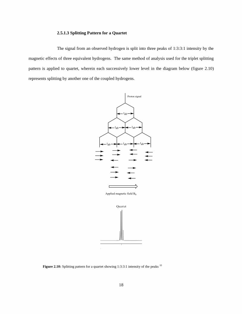
2.5.1.3 Splitting Pattern for a Quartet
The signal from an observed hydrogen is split into three peaks of 1:3:3:1 intensity by the
magnetic effects of three equivalent hydrogens. The same method of analysis used for the triplet splitting
pattern is applied to quartet, wherein each successively lower level in the diagram below (figure 2.10)
represents splitting by another one of the coupled hydrogens.
Figure 2.10: Splitting pattern for a quartet showing 1:3:3:1 intensity of the peaks 10
Page 28
19
2.6 Interpretation of a Predicted 1H NMR
Figure 2.11: Predicted 1H NMR of 3-(1H-indol-3-yl)propan-1-ol, a precursor to one of the primary amines.
The chemical shift for the 1H NMR (figure 2.11) ranges from 0 to 11 ppm, showing ten (10) different
types of protons. The three methylene protons (CH2) on the aliphatic chain are in different chemical
environments. The CH2 protons at chemical shift 1.76 ppm is the most shielded and hence is positioned
at a lower frequency (“upfield”) and are surrounded by four (4) neighboring protons on the adjacent
carbons, hence the peak is spilt into n+1 producing 5 peaks (quintet) where n is the number of
neighboring protons. The CH2 protons at 2.51 ppm occur at a higher ppm value (“downfield”) because
one of its neighboring carbons is an sp2 carbon which pulls electron density deshielding the protons and
has a splitting pattern of a triplet since there are two neighboring protons. The CH2 protons at 3.49 ppm
are furthest “downfield” compared to the other two methylene protons due to the oxygen atom directly
attached to its carbon atom. Oxygen is an electronegative atom that pulls electron density to a greater
degree than sp2 carbons. The peak signal is also a triplet due to the two neighboring protons. The proton
Page 29
20
directly attached to the oxygen (hydroxylic proton) is an exchangeable proton and is subjected to
hydrogen bonding. The chemical shift of the proton is usually found between ~0.5 ppm and ~4.0 ppm
depending on concentration of the sample. Changes in temperature and solvent will also shift the peak
position; this is due to the intermolecular hydrogen bonding. Hydrogen bonding decreases electron
density around the hydroxylic proton moving the proton peak to a higher frequency. If a more nonpolar
solvent is used, a decrease in the sample concentration disrupts hydrogen bonding, and the peak appears
at a lower frequency. An increase in the temperature of the sample has a similar effect. The protons on
the nitrogen atom (14
N) are subjected to partial or complete decoupling by the electrical quadrupole
moment of the 14
N nucleus, whose spin number I is 1. It is possible for these protons to undergo rapid,
intermediate, or slow exchange which affects the sharpness of the peak. Methine (also methyne) protons
usually show up in the aromatic region 6.5 ppm to 8.5 ppm. The CH proton at 7.16 ppm has a splitting
pattern of a singlet since there are no neighboring protons. The aromatic CH protons at 7.33 ppm and
7.57 ppm shows a doublet since they each have one neighboring proton each and are close in chemical
shift since they are in typically almost in the same chemical environment. The same holds true to the
other two CH protons at 6.98 ppm and 7.06 ppm.
2.7 Carbon-13 NMR (13
C)
Carbon-13 NMR spectroscopy is analogous to the 1H NMR spectroscopy identifying the carbon atoms in
an organic molecule as the proton NMR identifies hydrogen atoms. It is an application of nuclear
magnetic resonance to the 13
C isotope of carbon, whose natural abundance is only 1.1%, due to the fact
that the 12
C nucleus is not magnetically active having a spin number, I, of zero. Similar to 1H NMR the
spin number is ½ for 13
C isotope, however since the natural abundance is only 1.1% that of 12
C the overall
sensitivity of 13
C compared to 1H is about 1/5700
12 and as a result larger samples and longer times are
needed. In a broadband proton decoupled 13
C spectrum, the peaks are singlets unless the molecule
contains other magnetically active nuclei such as 2H, 31P, or 19F, and the peaks are distributed over a
Page 30
21
larger chemical shift range complied with the 1H spectrum. Also in comparison to the
1H spectrum,
13C
peak intensities do not correlate with the number of carbon atoms in a given peak. As with 1H NMR, the
13C NMR frequency axis is converted to a unit less scale δ units (ppm). As a result of the large range, 220
ppm from the TMS peak, and the sharpness of the decoupled peaks, impurities are readily detected.
Heteronuclear Multiple Bond Coherence (HMBC) is a 2D NMR method which gives data plotted in a
space defined by two frequency axes rather than one. It correlates the 1H with the
13C atoms and
capitalizes on the two and three bond couplings which provides more information compared to a 1D 13
C
NMR. HMBC was used to elucidate the structures of the intermediates and the products in this research
project and is discussed below.
2.8 Interpretation of a Predicted 13C NMR
Figure 2.12: Predicted 13C NMR of 3-(1H-indol-3-yl)propan-1-ol, a precursor to one of the primary amines
synthesized.
The chemical shift for the 13
C NMR (figure 2.12) ranges from 0 to 150 ppm, showing eleven (11)
different types of carbons. The three sp3 carbons along the aliphatic chain show up in the lower
Page 31
22
frequency region between 20 ppm to 70 ppm. The carbon at 62.4 ppm directly attached to the oxygen is
at a higher frequency compared to the other two sp3 because oxygen is more electronegative than carbon.
Compared to the respective protons on the 1H NMR the carbon at 25.4 ppm is more “upfield” than the
carbon at 34.6 ppm because it is directly attached to the Indole ring and the delocalization of the π
electrons increases electron density. The sp2 aromatic carbons show up in the 110-150 ppm range.
Substituents attached to the ring shift the chemical shift of the aromatic carbon ±35 ppm.
Page 32
23
Table 1: List of Chemicals used in the synthesis of the trp-like primary amines.
Name of Chemical Structure
phenylhydrazine
(4-chlorophenyl)hydrazine hydrochloride
(4-bromophenyl)hydrazine hydrochloride
(2,4-difluorophenyl)hydrazine hydrochloride
3,4-dihydro-2H-pyran
Phthalimide (Ph)
N-Methyl-2-pyrrolidone (NMP)
Sulfuric acid (H2SO4)
Dimethylacetamide (DMAC)
Diisopropyl azodicarboxylate (DIAD)
Page 33
24
Triphenylphosphine
Tetrahydrofuran (THF)
Benzyl Chloroformate (Cbz-Cl)
N,N-Diisopropylethylamine
4-Dimethylaminopyridine (DMAP)
Dichloromethane (DCM)
Hydrazine
Methanol (MeOH)
Hexane (Hex)
Ethyl Acetate (EA)
Page 34
25
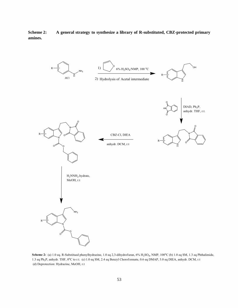
Scheme 1: A general strategy to synthesize a library of R-substituted, CBZ-protected primary
amines.
Page 35
26
CHAPTER THREE
Experimental Section
3-(1H-indol-3-yl)propan-1-ol, 1b
Phenyl hydrazine, 1a (2.86 mL, 27.74 mmol) was dissolved in sulfuric acid (6%, 45 mL) and N-methyl-2-
pyrrolidone (15 mL) at room temperature and heated to 100oC. 3,4-dihydro-2Hpyran (2.54 mL, 27.74
mmol,) was added drop wise over 20 minutes at 100oC. The reaction was monitored by TLC until all the
starting material was consumed. The reaction mixture was cooled to r.t. and a saturated solution of
sodium bicarbonate (65 mL) was added slowly. To the mixture, ethyl acetate (2 x 100 mL) was added
and the organic layers were extracted, combined and washed with brine (65 mL). The organic layer was
extracted and dried over Na2SO3 and concentrated leaving an oil to give compound 1b. No further
purification was carried out and compound was used in the next step. LCMS m/z (ESI) for C11H13NO
mw. 175.10 [M+H] 176.01
Page 36
27
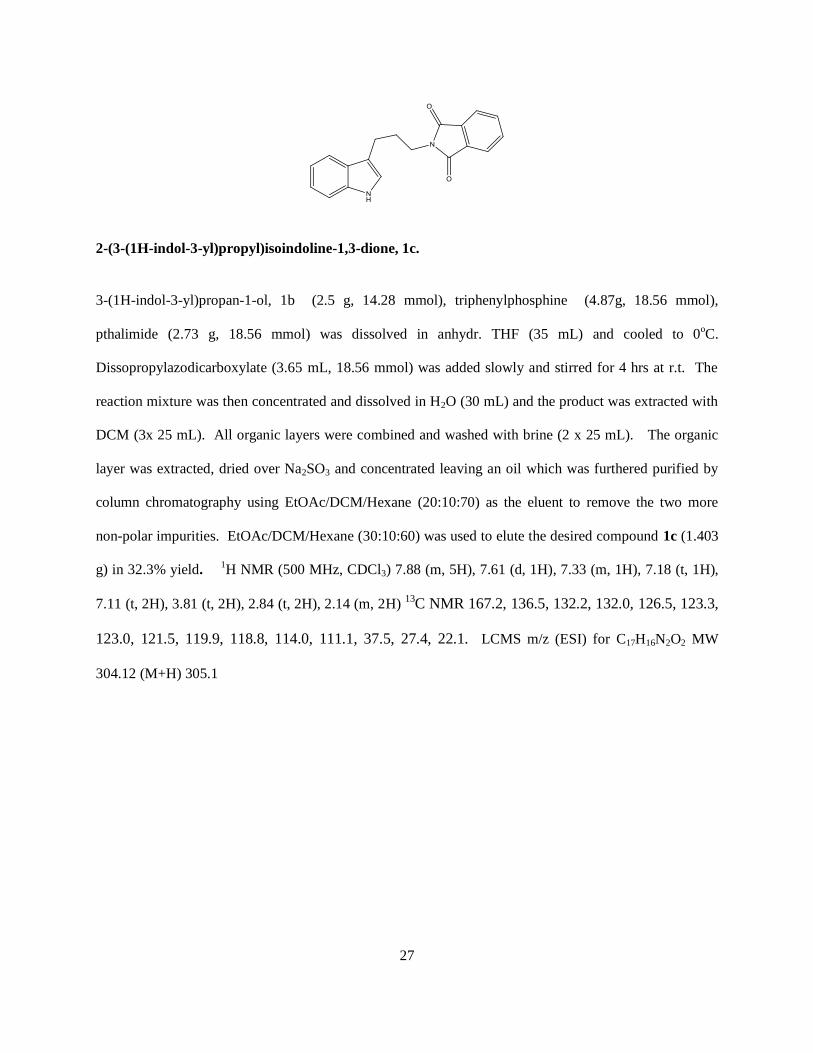
2-(3-(1H-indol-3-yl)propyl)isoindoline-1,3-dione, 1c.
3-(1H-indol-3-yl)propan-1-ol, 1b (2.5 g, 14.28 mmol), triphenylphosphine (4.87g, 18.56 mmol),
pthalimide (2.73 g, 18.56 mmol) was dissolved in anhydr. THF (35 mL) and cooled to 0oC.
Dissopropylazodicarboxylate (3.65 mL, 18.56 mmol) was added slowly and stirred for 4 hrs at r.t. The
reaction mixture was then concentrated and dissolved in H2O (30 mL) and the product was extracted with
DCM (3x 25 mL). All organic layers were combined and washed with brine (2 x 25 mL). The organic
layer was extracted, dried over Na2SO3 and concentrated leaving an oil which was furthered purified by
column chromatography using EtOAc/DCM/Hexane (20:10:70) as the eluent to remove the two more
non-polar impurities. EtOAc/DCM/Hexane (30:10:60) was used to elute the desired compound 1c (1.403
g) in 32.3% yield. 1H NMR (500 MHz, CDCl3) 7.88 (m, 5H), 7.61 (d, 1H), 7.33 (m, 1H), 7.18 (t, 1H),
7.11 (t, 2H), 3.81 (t, 2H), 2.84 (t, 2H), 2.14 (m, 2H) 13C NMR 167.2, 136.5, 132.2, 132.0, 126.5, 123.3,
123.0, 121.5, 119.9, 118.8, 114.0, 111.1, 37.5, 27.4, 22.1. LCMS m/z (ESI) for C17H16N2O2 MW
304.12 (M+H) 305.1
Page 37
28
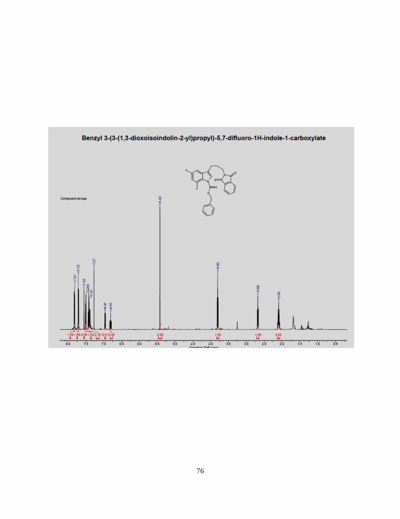
Benzyl 3-(3-(1,3-dioxoisoindolin-2-yl)propyl)-1H-indole-1-carboxylate, 1d.
2-(3-(1H-indol-3-yl)propyl)isoindoline-1,3-dione, 1c (1.10g, 3.62 mmol), 4-
Dimethylaminopyridine (0.27 g, 2.17 mmol) was dissolved in anhydrous DCM (20 mL). N,N-
Diisopropylethylamine (1.89 mL, 10.85 mmol) was then added. Benzyl chloroformate (1.2 mL,
9.04 mmol) was added dropwise at r.t. and the reaction mixture was stirred for 24h. The reaction
mixture was then cooled to 0oC and quenched with H2O (10 mL). DCM (20 mL) was added and
the organic layer was extracted and washed with brine (3 x 10 mL). The organic layer was dried
over Na2SO3 and concentrated leaving a yellow solid. The crude product was recrystallized with
100% ethanol to give compound 1d (0.64g) in 40.4%.
Benzyl 3-(3-aminopropyl)-1H-indole-1-carboxylate, 1e.
Benzyl 3-(3-(1,3-dioxoisoindolin-2-yl)propyl)-1H-indole-1-carboxylate, 1d, (0.5 g) was dissolved in
methanol (5 mL ). Hydrazine (64%, 5 mL) was added dropwise at 0oC and stirred for 30 minutes. The
reaction was monitored by TLC until all the starting material was completely consumed. The reaction
Page 38
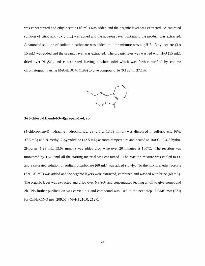
29
was concentrated and ethyl acetate (15 mL) was added and the organic layer was extracted. A saturated
solution of citric acid (3x 5 mL) was added and the aqueous layer containing the product was extracted.
A saturated solution of sodium bicarbonate was added until the mixture was at pH 7. Ethyl acetate (3 x
15 mL) was added and the organic layer was extracted. The organic later was washed with H2O (15 mL),
dried over Na2SO3 and concentrated leaving a white solid which was further purified by column
chromatography using MeOH/DCM (1:99) to give compound 1e (0.13g) in 37.1%.
3-(5-chloro-1H-indol-3-yl)propan-1-ol, 2b
(4-chlorophenyl) hydrazine hydrochloride, 2a (2.5 g, 13.69 mmol) was dissolved in sulfuric acid (6%,
37.5 mL) and N-methyl-2-pyrrolidone (12.5 mL) at room temperature and heated to 100oC. 3,4-dihydro-
2Hpyran (1.28 mL, 13.69 mmol,) was added drop wise over 20 minutes at 100oC. The reaction was
monitored by TLC until all the starting material was consumed. The reaction mixture was cooled to r.t.
and a saturated solution of sodium bicarbonate (60 mL) was added slowly. To the mixture, ethyl acetate
(2 x 100 mL) was added and the organic layers were extracted, combined and washed with brine (60 mL).
The organic layer was extracted and dried over Na2SO3 and concentrated leaving an oil to give compound
2b. No further purification was carried out and compound was used in the next step. LCMS m/z (ESI)
for C11H12ClNO mw. 209.06 [M+H] 210.0, 212.0.
Page 39
30
2-(3-(5-chloro-1H-indol-3-yl)propyl)isoindoline-1,3-dione, 2c
3-(5-chloro-1H-indol-3-yl)propan-1-ol, 2b (2.5 g, 11.96 mmol), triphenylphosphine (4.08g,
15.55mmol), pthalimide (2.29g, 15.55 mmol) was dissolved in anhydr. THF (35 mL) and cooled
to 0oC. Dissopropylazodicarboxylate (3.06 mL, 15.55 mmol) was added slowly and stirred for 4
hrs at r.t. The reaction mixture was then concentrated and dissolved in H2O (30 mL) and the
product was extracted with DCM (3x 25 mL). All organic layers were combined and washed
with brine (2 x 25 mL). The organic layer was extracted, dried over Na2SO3 and concentrated
leaving an oil which was furthered purified by column chromatography using
EtOAc/DCM/Hexane 20:10:70) as the eluent to remove the two more non-polar impurities.
EtOAc/DCM/Hexane (30:10:60) was used to elute the desired compound 2c (1.3 g) in 33%
yield. 1H NMR (500 MHz, CDCl3) 7.71-7.88 (m, 5H), 7.55 (d, 1H), 7.22 (d, 1H), 7.13 (m, 2H), 3.80
(t, 2H), 2.79 (t, 2H), 2.12 (m, 2H). 13C NMR 168.2, 134.5, 133.2, 132.0, 129.0, 126.5, 125.0, 123.0,
121.5, 115.0, 114.0, 37.5, 27.4, 22.1. LCMS m/z (ESI) for C19H15ClN2O2 mw. 338.08 [M+H]
339.0/241.0.
Page 40
31
Benzyl 5-chloro-3-(3-(1,3-dioxoisoindolin-2-yl)propyl)-1H-indole-1-carboxylate, 2d.
2-(3-(5-chloro-1H-indol-3-yl)propyl)isoindoline-1,3-dione, 2c (1.10g, 3.25 mmol), 4-
Dimethylaminopyridine (0.24 g, 1.95 mmol) was dissolved in anhydrous DCM (20 mL). N,N-
Diisopropylethylamine (1.7 mL, 9.76 mmol) was then added. Benzyl chloroformate (1.2 mL,
8.95 mmol) was added dropwise at r.t. and the reaction mixture was stirred for 24h. The reaction
mixture was then cooled to 0oC and quenched with H2O (10 mL). DCM (20 mL) was added and
the organic layer was extracted and washed with brine (3 x 10 mL). The organic layer was dried
over Na2SO3 and concentrated leaving a yellow solid. The crude product was recrystallized with
100% ethanol to give compound 2d (0.71g) in 46% yield. 1H NMR (500 MHz, CDCl3) 7.78 (m,
2H), 7.68 (m, 2H), 7.46-7.40 (m, 6H), 5.40 (s, 2H), 3.78 (t, 2H), 2.68 (t, 2H), 2.08 (m, 2H). 13C
NMR 168.5, 152.6, 133.4, 132.2, 132.0, 128.9, 127.2, 126.9, 126.2, 125.0, 124.5, 123.7, 122.1,
121.0, 119.0, 118.0, 69.0, 38.2, 27.0, 22.0.
Page 41
32
Benzyl 3-(3-aminopropyl)-5-chloro-1H-indole-1-carboxylate, 2e.
Benzyl 5-chloro-3-(3-(1,3-dioxoisoindolin-2-yl)propyl)-1H-indole-1-carboxylate, 2d (0.7 g) was
dissolved in methanol (7 mL ). Hydrazine (64%, 7 mL) was added dropwise at 0oCand stirred
for 30 minutes. The reaction was monitored by TLC until all the starting material was
completely consumed. The reaction was concentrated and ethyl acetate (2 x 15 mL) was added
and the organic layer was extracted. A saturated solution of citric acid (3x 7 mL) was added and
the aqueous layer containing the product was extracted. A saturated solution of sodium
bicarbonate was added until the mixture was at pH 7. Ethyl acetate (3 x 15 mL) was added and
the organic layer was extracted. The organic later was washed with H2O (15 mL), dried over
Na2SO3 and concentrated leaving a white solid which was further purified by column
chromatography using MeOH/DCM (1:99) to give compound 2e (0.21g) in 41.4%. LCMS m/z
(ESI) for C19H19ClN2O2 mw. 342.11 [M+H] 209.0
3-(5-bromo-1H-indol-3-yl)propan-1-ol, 3b.
(4-bromophenyl) hydrazine hydrochloride, 3a (2.5 g, 11.19 mmol) was dissolved in sulfuric acid (6%,
37.5 mL) and N-methyl-2-pyrrolidone (12.5 mL) at room temperature and heated to 100oC. 3,4-dihydro-
Page 42
33
2Hpyran (1.02 mL, 11.19 mmol,) was added drop wise over 20 minutes at 100oC. The reaction was
monitored by TLC until all the starting material was consumed. The reaction mixture was cooled to r.t.
and a saturated solution of sodium bicarbonate (60 mL) was added slowly. To the mixture, ethyl acetate
(2 x 100 mL) was added and the organic layers were extracted, combined and washed with brine (60 mL).
The organic layer was extracted and dried over Na2SO3 and concentrated leaving an oil to give compound
2b. No further purification was carried out and compound was used in the next step. LCMS m/z (ESI)
for C11H12BrNO mw. 253.01 [M+H] 254.0/256.0.
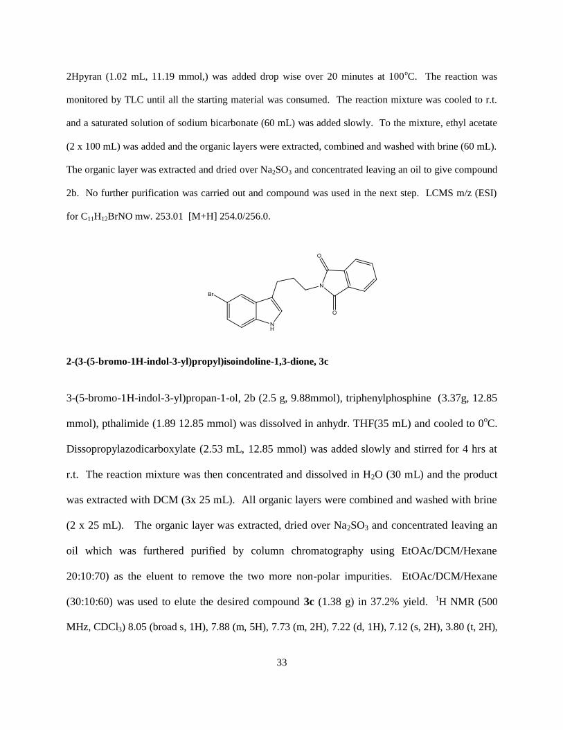
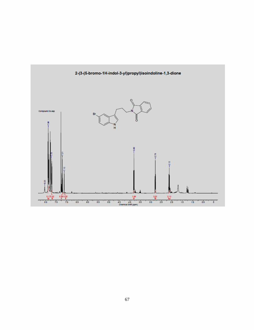
2-(3-(5-bromo-1H-indol-3-yl)propyl)isoindoline-1,3-dione, 3c
3-(5-bromo-1H-indol-3-yl)propan-1-ol, 2b (2.5 g, 9.88mmol), triphenylphosphine (3.37g, 12.85
mmol), pthalimide (1.89 12.85 mmol) was dissolved in anhydr. THF(35 mL) and cooled to 0oC.
Dissopropylazodicarboxylate (2.53 mL, 12.85 mmol) was added slowly and stirred for 4 hrs at
r.t. The reaction mixture was then concentrated and dissolved in H2O (30 mL) and the product
was extracted with DCM (3x 25 mL). All organic layers were combined and washed with brine
(2 x 25 mL). The organic layer was extracted, dried over Na2SO3 and concentrated leaving an
oil which was furthered purified by column chromatography using EtOAc/DCM/Hexane
20:10:70) as the eluent to remove the two more non-polar impurities. EtOAc/DCM/Hexane
(30:10:60) was used to elute the desired compound 3c (1.38 g) in 37.2% yield. 1H NMR (500
MHz, CDCl3) 8.05 (broad s, 1H), 7.88 (m, 5H), 7.73 (m, 2H), 7.22 (d, 1H), 7.12 (s, 2H), 3.80 (t, 2H),
Page 43
34
2.78 (t, 2H), 2.12 (m, 2H), 13
C NMR 168.2, 136.5, 132.2, 132.0, 131.9, 128.5, 124.5, 123.7, 123.0,
115.0, 113.5, 39.5, 29.0, 21.0 LCMS m/z (ESI) for C19H15BrN2O2 mw. 382.03 [M+H] 383.0/385.0
Benzyl 5-bromo-3-(3-(1,3-dioxoisoindolin-2-yl)propyl)-1H-indole-1-carboxylate, 3d.
2-(3-(5-bromo-1H-indol-3-yl)propyl)isoindoline-1,3-dione, 3c (1.10g, 2.88 mmol), 4-
Dimethylaminopyridine (0.21 g, 1.73 mmol) was dissolved in anhydrous DCM (20 mL). N,N-
Diisopropylethylamine (1.5 mL, 8.64 mmol) was then added. Benzyl chloroformate (1.5 mL,
7.20 mmol) was added dropwise at r.t. and the reaction mixture was stirred for 24h. The
reaction mixture was then cooled to 0oC and quenched with H2O (10 mL). DCM (20 mL) was
added and the organic layer was extracted and washed with brine (3 x 10 mL). The organic layer
was dried over Na2SO3 and concentrated leaving a yellow solid. The crude product was
recrystallized with 100% ethanol to give compound 3d (0.56g) in 37.6%.. 1H NMR (500 MHz,
CDCl3) 7.78 (m, 2H), 7.68 (m, 2H), 7.46-7.38 (m, 7H), 5.40 (s, 2H), 3.78 (t, 2H), 2.68 (t, 2H), 2.08
(m, 2H). 13C NMR (500 MHz, CDCl3) 169.5, 150.0, 136.1, 135.5, 133.0, 132.2, 132.0, 130.0, 126.0,
125.0, 124.2, 122.0, 120.0, 118.5, 118.0, 68.9, 39.5, 29.0, 22.0.
Page 44
35
Benzyl 3-(3-aminopropyl)-5-bromo-1H-indole-1-carboxylate, 3e.
Benzyl 5-bromo-3-(3-(1,3-dioxoisoindolin-2-yl)propyl)-1H-indole-1-carboxylate, 3d (0.5 g) was
dissolved in methanol (5 mL ). Hydrazine (64%, 5 mL) was added dropwise 0oCand stirred for
30 minutes.. The reaction was monitored by TLC until all the starting material was completely
consumed. The reaction was concentrated and ethyl acetate (2 x 15 mL) was added and the
organic layer was extracted. A saturated solution of citric acid (3x 5 mL) was added and the
aqueous layer containing the product was extracted. A saturated solution of sodium bicarbonate
was added until the mixture was at pH 7. Ethyl acetate (3 x 15 mL) was added and the organic
layer was extracted. The organic later was washed with H2O (15 mL), dried over Na2SO3 and
concentrated leaving a white solid which was further purified by column chromatography using
MeOH/DCM (1:99) to give compound 3e (0.12g) in 31.8%. LCMS m/z (ESI) for C19H19BrN2O2
mw. 386.06 [M+H] 253.0/255.0
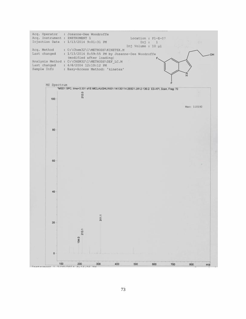
3-(5,7-difluoro-1H-indol-3-yl)propan-1-ol, 4b
(2,4-difluorophenyl)hydrazine hydrochloride, 4a (2.0 g, 11.07 mmol) was dissolved in sulfuric acid (6%,
30 mL) and N-methyl-2-pyrrolidone (10 mL) at room temperature and heated to 100oC. 3,4-dihydro-
Page 45
36
2Hpyran (1.01 mL, 11.07 mmol,) was added drop wise over 20 minutes at 100oC. The reaction was
monitored by TLC until all the starting material was consumed. The reaction mixture was cooled to r.t.
and a saturated solution of sodium bicarbonate (60 mL) was added slowly. To the mixture, ethyl acetate
(2 x 100 mL) was added and the organic layers were extracted, combined and washed with brine (60 mL).
The organic layer was extracted and dried over Na2SO3 and concentrated leaving an oil to give compound
2b. No further purification was carried out and compound was used in the next step. LCMS m/z (ESI)
for C11H15F2NO mw. 211.08 [M+H] 212.0
2-(3-(5,7-difluoro-1H-indol-3-yl)propyl)isoindoline-1,3-dione, 4c
3-(5,7-difluoro-1H-indol-3-yl)propan-1-ol, 4b (2.47 g, 11.69mmol), triphenylphosphine
(3.99g,15.19 mmol), pthalimide (2.24g, 15.19 mmol) was dissolved in anhydr. THF (30 mL) and
cooled to 0oC. Dissopropylazodicarboxylate (3.0 mL, 15.19 mmol) was added slowly and stirred
for 4 hrs at r.t. The reaction mixture was then concentrated and dissolved in H2O (30 mL) and
the product was extracted with DCM (3x 25 mL). All organic layers were combined and washed
with brine (2 x 25 mL). The organic layer was extracted, dried over Na2SO3 and concentrated
leaving an oil which was furthered purified by column chromatography using
EtOAc/DCM/Hexane 20:10:70) as the eluent to remove the two more non-polar impurities.
EtOAc/DCM/Hexane (30:10:60) was used to elute the desired compound 4c (1.76 g) in 44.3%
Page 46
37
yield. 1H NMR (500 MHz, CDCl3) 7.85 (m, 5H), 7.14 (m, 1H), 7.01 (s, 1H), 6.68 (s, 1H), 3.75 (t,
2H), 2.74 (t, 2H), 2.08 (m, 2H). LCMS m/z (ESI) for C19H14F2N2O2 mw. 340.10 [M+H] 341.0
Benzyl 3-(3-(1,3-dioxoisoindolin-2-yl)propyl)-5,7-difluoro-1H-indole-1-carboxylate, 4d.
2-(3-(5,7-difluoro-1H-indol-3-yl)propyl)isoindoline-1,3-dione, 4c (1.50g, 4.41 mmol), 4-
Dimethylaminopyridine (0.32 g, 2.65 mmol) was dissolved in anhydrous DCM (20 mL). N,N-
Diisopropylethylamine (1.7 mL, 9.76 mmol) was then added. Benzyl chloroformate (1.46 mL,
11.03 mmol) was added dropwise at r.t and the reaction mixture was stirred for 24h. The
reaction mixture was then cooled to 0oC and quenched with H2O (10 mL). DCM (20 mL) was
added and the organic layer was extracted and washed with brine (3 x 10 mL). The organic layer
was dried over Na2SO3 and concentrated leaving a yellow solid. The crude product was
recrystallized with 100% ethanol to give compound 4d in (0.811 g) in 38.8% yield. %. 1H NMR
(500 MHz, CDCl3) 7.81 (m, 2H), 7.72 (m, 2H), 7.55-7.50 (m, 4H), 7.41 (d, 1H), 6.97 (t, 1H), 5.42 (s,
2H), 3.8 (t, 2H), 2.68 (t, 2H), 2.09 (m, 2H). 13C NMR 170.0,168.50, 160.3, 150.0, 136.5, 132.2,
132.0, 129.0, 127.0, 124.0, 121.0, 118.0, 103.0, 78.5, 69.5, 35.0, 26.0, 20.5
Page 47
38
Benzyl 3-(3-aminopropyl)-5,7-difluoro-1H-indole-1-carboxylate, 4e.
Benzyl 3-(3-(1,3-dioxoisoindolin-2-yl)propyl)-5,7-difluoro-1H-indole-1-carboxylate, 4d (0.67 g)
was dissolved in methanol (7 mL ). Hydrazine (64%, 7 mL) was added dropwise at 0oC and
stirred for 30 minutes. The reaction was monitored by TLC until all the starting material was
completely consumed. The reaction was concentrated and ethyl acetate (2 x 15 mL) was added
and the organic layer was extracted. A saturated solution of citric acid (3x 5 mL) was added and
the aqueous layer containing the product was extracted. A saturated solution of sodium
bicarbonate was added until the mixture was at pH 7. Ethyl acetate (3 x 15 mL) was added and
the organic layer was extracted. The organic later was washed with H2O (15 mL), dried over
Na2SO3 and concentrated leaving a white solid which was further purified by column
chromatography using MeOH/DCM (1:99) to give compound 2e (0.29g) in 59.2%. LCMS m/z
(ESI) for C19H18F2N2O2 mw. 344.13 [M+H] 211.1
Page 48
39
CHAPTER FOUR
Discussion
As previously discussed, the major goal of this thesis project was to develop a general procedure
to synthesize a library of trp-like primary amines peptoid side chain groups that will be used in the
synthesis of a cyclic β-hairpin – like scaffolds. The generalized four (4) step scheme faced many
challenges; purification processes and optimization of product yields. The reaction time in the first step,
the Indole formation, varied depending on the substitute on the phenyl ring; whereas in the other steps the
reaction time was the same. The product yields in each step were affected by a number of factors
including light sensitivity of the Indole ring, moisture sensitivity and unfavorable side reactions, and
hence specific conditions were developed to optimize product yields based on proposed mechanisms for
each reaction step.
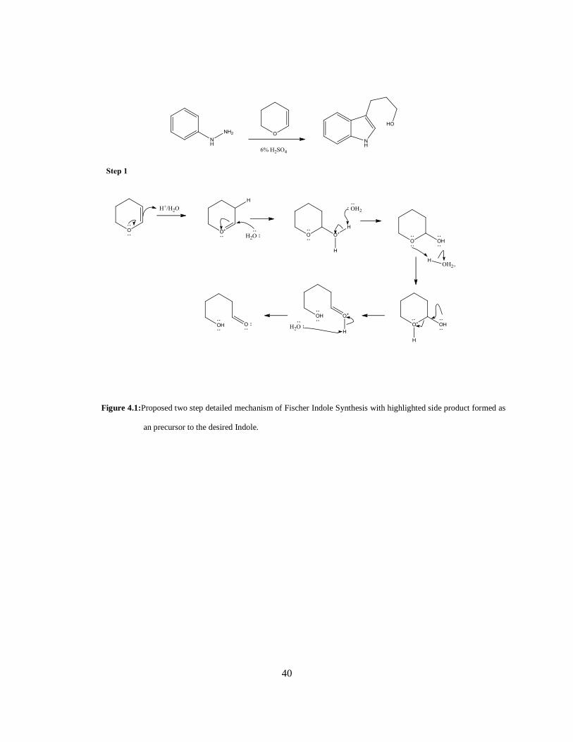
Fischer Indole Synthesis (Step 1)
In the cyclization of the Indole ring, the product yield was affected by the formation of two side products,
as this was dependent on the concentration of the acid and the time allotted for the reaction. An
appropriate organic solvent was required for the starting material, hydrazine, to fully dissolve prior to the
addition of the pyran. The hydrazine used was specifically dissolved in a 3:1 ratio of H2SO4 (6%): NMP
to minimize the production of the hydrazone (figure 4.1) and the acetal protected product of the OH
group.
Page 49
40
Figure 4.1:Proposed two step detailed mechanism of Fischer Indole Synthesis with highlighted side product formed as
an precursor to the desired Indole.
Page 50
41
Scheme 2 cont’d
Page 51
42
When 4 mL of H2SO4 (6%) was used the acetal side product was formed at a higher concentration than
the desired Indole product. Thus, two different organic solvents were used and the appropriate ratio was
sort out which would not have affected the concentration of the acid was used. It was discovered that
NMP was more favorable over DMAC minimizing other side reactions. Also, the concentration of the
acid determined the formation of the hydrazone. Hence various ratios of H2SO4 (6%): NMP were used
and all other reaction conditions were kept constant, i.e. temperature, reactant ratios and time of the
reaction and volume of the solvent and acid used. The same hydrazine ((4-chlorophenyl)hydrazine) was
used in all testing reactions. The formation of the product (3-(5-chloro-1H-indol-3-yl)propan-1-ol)
compared to the two side products was monitored by LC/MS by measuring the area under the peak in the
UV region of the chromatogram.
The reaction was carried out under a continuous flow of N2 (g) and in the absence of light. The deionized
water used to make up the 6% H2SO4 was bubbled with N2 (g) for 5 minutes to remove all oxygen. In the
presence of light and oxygen the indole ring undergoes oxidation at the carbon adjacent to the NH group
in the ring. This by-product (Figure 4.2) does not undergo CBZ protection as readily as the Indole ring
because the nitrogen lone pair of electrons are less available, due to resonance in the amide bond formed,
to attack the CBZ group in the third step.
Figure 4.2: Oxidation of Indole ring showing resonance of the nitrogen lone pairs of electrons in the amide bond
Page 52
43
Time allotted for the reaction played another factor in the Fischer Indole cyclization. The longer the
reaction was exposed to the acid at 100OC the more acetal product was formed and greater chance of
dehydration of the OH group in the aliphatic chain (figure 4.3). However, efficient time was required to
ensure all of the hydrazone was converted to the Indole.
Figure 4.3: Dehydration of the OH group
The substituent on the phenyl ring also impacted the time taken for the cyclization of the ring. It was
discovered that the more electron withdrawing effect of the halogen the longer it took for the hydrazone
to disappear. As seen in the mechanism (scheme 3) the electrons from the phenyl ring attacked the
hydrogen atom in the imine intermediates. The more electron withdrawing the halogen on the ring the
less nucleophilic it becomes thus slower reaction times. It was important to monitor the reaction for each
hydrazine used. Further work would be to explore the use of (2,4-dimethylphenyl)hydrazine
hydrochloride and p-tolylhydrazine hydrochloride where there is a methyl group in the ortho and para,
and para position on the ring, respectively to reduce reaction times.
Mitsunobu Reaction (Step 2)
This reaction is useful for converting the OH group into the desired NH2 group once the phthalimide
group is removed in the final step. This reaction is moisture sensitive and required the product to be
completely dry. The solvent (THF) used was dried prior to use in the reaction. In the present of water,
the hydroxyl group from water competes with that of the alcohol and the side product Triphenylphosphine
oxide (OP(C6H5)3) would form which is a white solid that would precipitate out with the product as seen
in the figure 4.4 below.
Page 53
44
Figure 4.4: Proposed three step detailed mechanism for the Mitsunobu reaction.
Carboxybenzyl (Cbz) Protection (Step 3)
Carboxylbenzyl is a carbamate used in the protection of the secondary amine. Benzyl chloroformate is
used to introduce the Cbz group in a simple SN2 reaction (figure 4.5) where the secondary amine attacks
the carbonyl group displacing the DMAP as a good leaving group. A weak base (DIEA) is used to
Page 54
45
remove the proton from the amine. This reaction is also moisture sensitive and the solvent (DCM) was
dried prior to using it in the reaction. It was also noted that the reaction didn’t go to completion. An
additional catalytic amount of DMAP was added during the progress of the reaction. This improved the
yield from ~25% to ~ 35%. The HMBC confirms the carbonyl carbon of the Cbz protecting group at
~150 ppm shown in the supporting data.
Figure 4.5: Proposed mechanism for Cbz Protection of the secondary amine.
Page 55
46
Phthalimide Deprotection (Step 4)
In the final step the phthalimide group is removed using 64% hydrazine at 0oC. This reaction faced
challenges in optimizing the product yield. The Cbz protected starting material was first dissolved in
MeOH at 0oC by adding small amounts of DCM and the hydrazine was added slowly. This was
important to ensure that the Cbz group was not removed. It was initially observed that adding hydrazine
at r.t. removed the Cbz group with no product formation. Therefore the reaction was maintained at 0oC
and monitor by TLC every 5 minutes. It was noted that for longer reaction times more of the less desired
product was formed as seen in figure 4.6. Further work will be carried out to optimize the product yield
by substituting the Cbz protecting group with a Boc protecting group which is not base labile.
Figure 4.6: Proposed mechanism for the Deprotection of the phthalimide group.
Page 56
47
CHAPTER FIVE
Conclusion
As mentioned above, the aim of this thesis project was to develop a generalized scheme to synthesis a
library of primary amines starting with different hydrazines. As explored thus far, hydrazines with
electron withdrawing substituents on the phenyl ring yielded the desired product. It would be worthwhile
to explore hydrazines with electron donating groups (figure 5.1) that would favor the Fischer Indole
cyclization, possible at lower acid concentrations and short reaction times due to its increase
nucleophilicity of the phenyl ring. It is anticipated that this would reduce the formation of the acetal
protected side product.
Figure 5.1 Fischer Indoles synthesized from hydrazines with electron donating groups.
It would be worthwhile to also explore Indoles with shorter aliphatic chains. These Indoles (figure 5.2)
will be synthesized from 2,3-dihydrofuran instead of 3,4-dihydro-2Hpyran following the developed
scheme as seen in scheme 2. It can be proposed that since the OH group is closer to the Indole ring the
Page 57
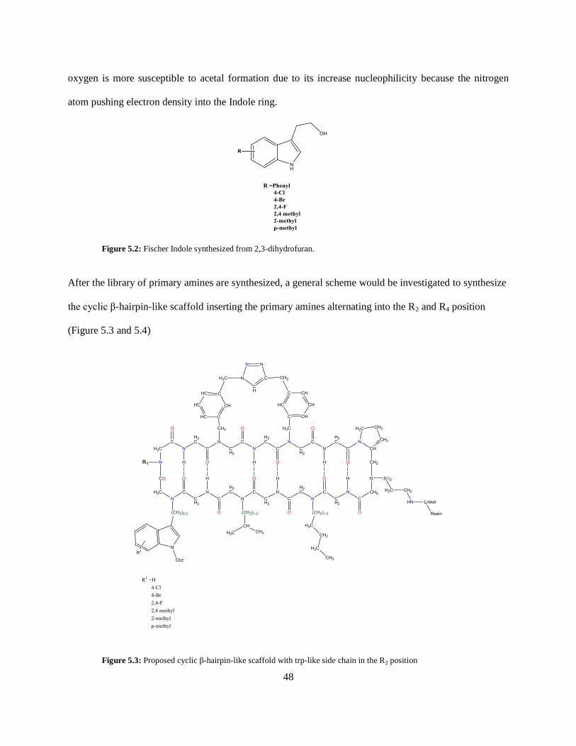
48
oxygen is more susceptible to acetal formation due to its increase nucleophilicity because the nitrogen
atom pushing electron density into the Indole ring.
Figure 5.2: Fischer Indole synthesized from 2,3-dihydrofuran.
After the library of primary amines are synthesized, a general scheme would be investigated to synthesize
the cyclic β-hairpin-like scaffold inserting the primary amines alternating into the R2 and R4 position
(Figure 5.3 and 5.4)
Figure 5.3: Proposed cyclic β-hairpin-like scaffold with trp-like side chain in the R2 position
Page 58
49
Figure 5.4: Proposed Cyclic β-hairpin-like scaffold with trp-like side chain in the R4 position
The synthesis of the Cyclic β-hairpin-like scaffolds will be carried out on using solid support chemistry
which will be explored in further work.
Page 59
50
REFERENCES
1. Zuckermann, R. N., (1992) Efficient method for the preparation of peptoids [oligo (N-substituted
glycines)] by submonomer solid-phase synthesis, Journal of the American Chemical society, 114
(26), 1, February 01, 2014.
2. Brown, N. J., Johansson, J., Barron, A. E., (2008), Biomimicry of Surfactant Protein C
3. Gebhard A.W., Jain, P., Nair R. R., Emmons M.F., Argilagos R. F., Koomen J. M., McLauglin,
M. L., Hazelhurst, L.A., (2013, November 12) MTI-101 (cyclized HYD1) binds a CD44
containing complex and induces necrotic cell death in myeloma.
4. McLaughlin, M. L., (2013) Proposal
5. Geiss,F., (1987) Fundamentals of thin layer chromatography, February 02, 2014
6. Manetsch, R., (2010) MS –Core Techniques and Ionization Processes. PowerPoint presented in
class at the University of South Florida, Fl.
7. Thurman, E. M., Ferrer, I., (2003) Liquid Chromatography/ Mass Spectroscopy, MS/MS &Time
of Flight MS: analysis of emerging contaminants. February 02, 2014.
8. Herbert, C., Johnstone, R.,(2003) Mass Spectroscopy Basic, CRC Press LLC
9. Manetsch, R., (2010) MS –Mass Analyzers. PowerPoint presented in class at the University of
South Florida, Fl.
10. Solomons, T.G., Fryhle C.B., 2011, Organic Chemistry, University of South Florida, John Wiley
& Sons, Inc.
11. Silverstein R.M., Francis W. X., Kiemle D. J., 2005, State University of New York, John Wiley
& Sons, Inc.
Page 61
52
Table 2: Fischer Indole Synthesis from 3,4-dihydro-2Hpyran and Phenyl Hydrazine.HCl in 6% H2SO4 in
NMP
Entry Hydrazine Indole Time (h)
1 1.5
1a 1b
2 2.0
2a 2b
3 1.5
3a 3b
4
2.5
4a 4b
Page 62
53
Scheme 2: A general strategy to synthesize a library of R-substituted, CBZ-protected primary
amines.
Page 63
54
SUPPORTING DATA
Page 89
80
About the Author
Ms. Josanne-Dee Woodroffe was born in 1983 in Port of Spain, Trinidad. She grew up in
Chaguanas,Trinidad and attended high school at St. Joseph’s Convent, Port of Spain where she received
her G.C.E O’level and A’level passes with a focus in Natural Sciences. After working as a medical
assistant to Dr. Tim Gopeesingh, obstetrician/gynecologist, MP, she continued her studies at the
University of the West Indies, St. Augustine where she received her B.Sc. in Chemistry and a minor in
Analytical Chemistry, 2006. In 2006, she moved to Tampa, Florida and obtained a teaching certificate in
Chemistry, Grades 6 thru 12 and worked as an educator for Hillsborough County for three (3) years. Ms.
Woodroffe started her career at the University of South Florida in Fall 2010 as a graduate student in Dr.
Mark McLaughlin’s group. She continued her research in synthetic chemistry to receive a masters degree
in Spring 2014.