1 A System Level Description of the ATA David R. DeBoer and John. W. Dreher April 23, 2003 ABSTRACT The Allen Telescope Array will consist of approximately 350 6.1-meter offset Gregorian dishes arrayed at the Hat Creek Radio Observatory site operating over the frequency range of about 500 MHz – 11.2 GHz. The ATA architecture, composed of four broad systems, each of which comprises several sub-systems, may be summarized as follows: antenna (base, telescope), signal path (front-end, RF converter, digitizer, IF processor, back-end interface); control (element, converter, processor, environment, operations); site (infrastructure, configuration, rfi monitor). This memo discusses the overall architecture, then each system and sub-system in turn. I. INTRODUCTION The Allen Telescope Array (ATA) will consist of approximately 350 6.1-meter offset Gregorian dishes arrayed at the Hat Creek Radio Observatory site. Given the number of antennas and large size of the primary beam, this array will have an unprecedented amount of flexibility in observing. A hierarchical assortment of individual users may simultaneously use the array to observe a different part of the sky at an independent frequency or image the sky at one or more frequencies. The ATA architecture, composed of four broad systems, each of which comprises several sub-systems, may be summarized as follows: Table I System Sub-system Antenna ANT Base Telescope BASE TEL Signal path SP Front-end RF converter IF processor Back-end interface FE RFC IFP BEI Control CTRL Element Converter Processor Environment Operations ELC CNVC PRCC ENVM OPS Site SITE Infrastructure Configuration RFI monitor INFRA CONFIG RFIM This memo discusses the overall architecture, then each system and subsystem in turn. II. OVERALL ARCHITECTURE The ATA has four main conceptual systems: (1) the antenna receives the radiation from free space, (2) the signal path comprises all of the systems to convey the radiation from the ATA Memo #23
Transcript
1
A System Level Description of the ATA
David R. DeBoer and John. W. Dreher
April 23, 2003 ABSTRACT
The Allen Telescope Array will consist of approximately 350 6.1-meter offset Gregorian dishes arrayed at the Hat Creek Radio Observatory site operating over the frequency range of about 500 MHz – 11.2 GHz. The ATA architecture, composed of four broad systems, each of which comprises several sub-systems, may be summarized as follows: antenna (base, telescope), signal path (front-end, RF converter, digitizer, IF processor, back-end interface); control (element, converter, processor, environment, operations); site (infrastructure, configuration, rfi monitor). This memo discusses the overall architecture, then each system and sub-system in turn. I. INTRODUCTION
The Allen Telescope Array (ATA) will consist of approximately 350 6.1-meter offset Gregorian dishes arrayed at the Hat Creek Radio Observatory site. Given the number of antennas and large size of the primary beam, this array will have an unprecedented amount of flexibility in observing. A hierarchical assortment of individual users may simultaneously use the array to observe a different part of the sky at an independent frequency or image the sky at one or more frequencies.
The ATA architecture, composed of four broad systems, each of which comprises several sub-systems, may be summarized as follows:
Table I
System Sub-system Antenna ANT
Base Telescope
BASE TEL
Signal path SP
Front-end RF converter IF processor Back-end interface
FE RFC IFP BEI
Control CTRL
Element Converter Processor Environment Operations
ELC CNVC PRCC ENVM OPS
Site SITE
Infrastructure Configuration RFI monitor
INFRA CONFIGRFIM
This memo discusses the overall architecture, then each system and subsystem in turn. II. OVERALL ARCHITECTURE
The ATA has four main conceptual systems: (1) the antenna receives the radiation from free space, (2) the signal path comprises all of the systems to convey the radiation from the
ATA Memo #23
2
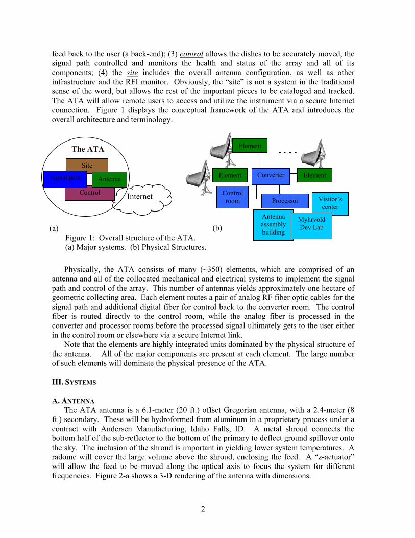
feed back to the user (a back-end); (3) control allows the dishes to be accurately moved, the signal path controlled and monitors the health and status of the array and all of its components; (4) the site includes the overall antenna configuration, as well as other infrastructure and the RFI monitor. Obviously, the “site” is not a system in the traditional sense of the word, but allows the rest of the important pieces to be cataloged and tracked. The ATA will allow remote users to access and utilize the instrument via a secure Internet connection. Figure 1 displays the conceptual framework of the ATA and introduces the overall architecture and terminology.
Physically, the ATA consists of many (~350) elements, which are comprised of an
antenna and all of the collocated mechanical and electrical systems to implement the signal path and control of the array. This number of antennas yields approximately one hectare of geometric collecting area. Each element routes a pair of analog RF fiber optic cables for the signal path and additional digital fiber for control back to the converter room. The control fiber is routed directly to the control room, while the analog fiber is processed in the converter and processor rooms before the processed signal ultimately gets to the user either in the control room or elsewhere via a secure Internet link.
Note that the elements are highly integrated units dominated by the physical structure of the antenna. All of the major components are present at each element. The large number of such elements will dominate the physical presence of the ATA. III. SYSTEMS A. ANTENNA
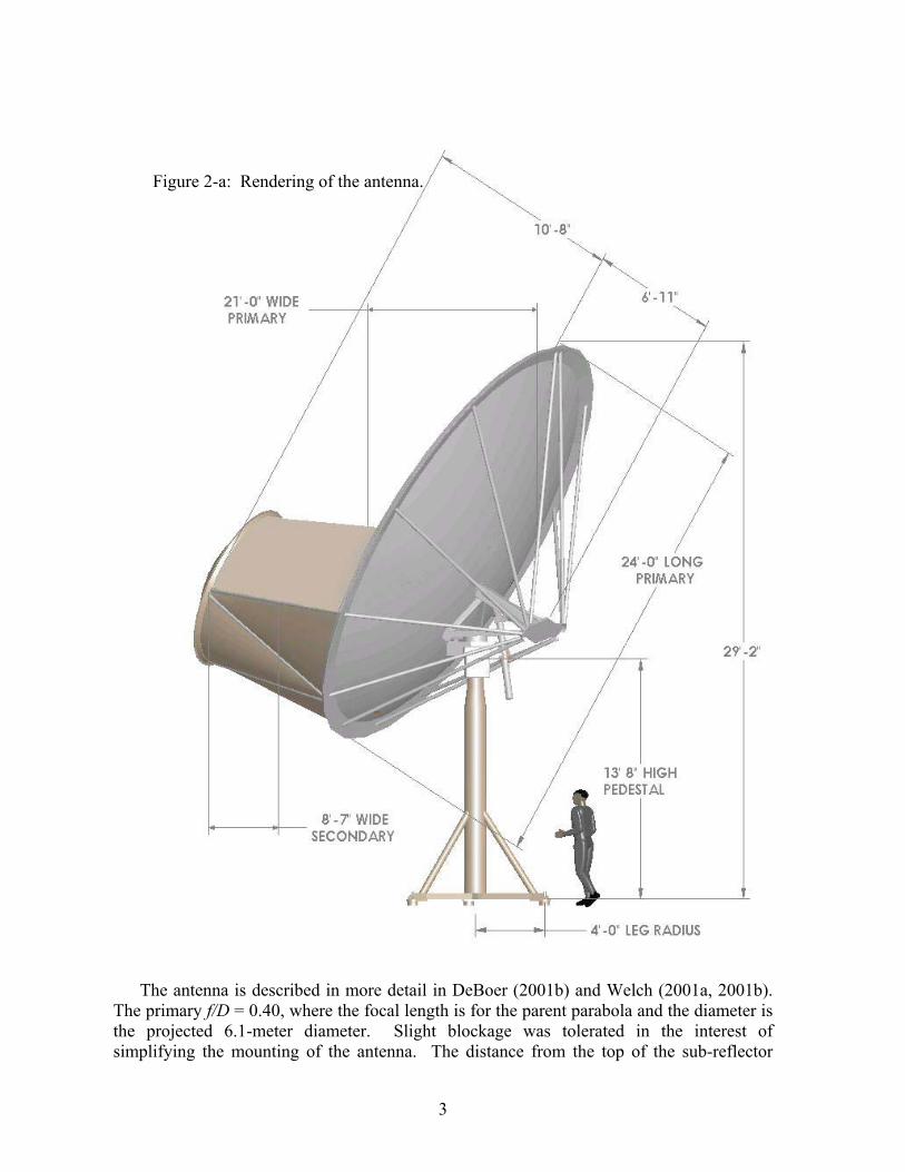
The ATA antenna is a 6.1-meter (20 ft.) offset Gregorian antenna, with a 2.4-meter (8 ft.) secondary. These will be hydroformed from aluminum in a proprietary process under a contract with Andersen Manufacturing, Idaho Falls, ID. A metal shroud connects the bottom half of the sub-reflector to the bottom of the primary to deflect ground spillover onto the sky. The inclusion of the shroud is important in yielding lower system temperatures. A radome will cover the large volume above the shroud, enclosing the feed. A “z-actuator” will allow the feed to be moved along the optical axis to focus the system for different frequencies. Figure 2-a shows a 3-D rendering of the antenna with dimensions.
(b) (a)
.…Converter
Processor Control room
Antenna assembly building
Element
Visitor’scenter
Myhrvold Dev Lab
Element Element
Internet
Site
The ATA
Control
Signal path Antenna
Figure 1: Overall structure of the ATA. (a) Major systems. (b) Physical Structures.
3
The antenna is described in more detail in DeBoer (2001b) and Welch (2001a, 2001b).
The primary f/D = 0.40, where the focal length is for the parent parabola and the diameter is the projected 6.1-meter diameter. Slight blockage was tolerated in the interest of simplifying the mounting of the antenna. The distance from the top of the sub-reflector
Figure 2-a: Rendering of the antenna.
4
normal to the mid-point of the primary, yc, is 0.45D. Figure 2-b shows the amount of blockage at boresight and a cross-sectional view. The calculated aperture efficiency while in focus is about 63%. The (nearly) unblocked aperture produces extremely low sidelobes. The 3-dB beamwidth may reasonably be approximated as:
.][
5.33 GHzfdB
°≈θ
As a system, the antenna is comprised of two sub-systems: (1) the telescope and (2) the base. 1. Telescope
The telescope may basically be summarized as the thing you point. It is comprised of: (a) the alidade; (b) the optics, which includes the reflectors and support structure); (c) the shroud; (d) the radome; (e) the motive, which consists of the gears, bearings and az/el/z motor drive pairs); and (f) the twister subsub-systems. 2. Base
The base is comprised of (a) the foundation and (b) the pedestal and holds the telescope up. The foundation consists of three reinforced grout piers to which the tripod of the pedestal is attached. B. SIGNALPATH
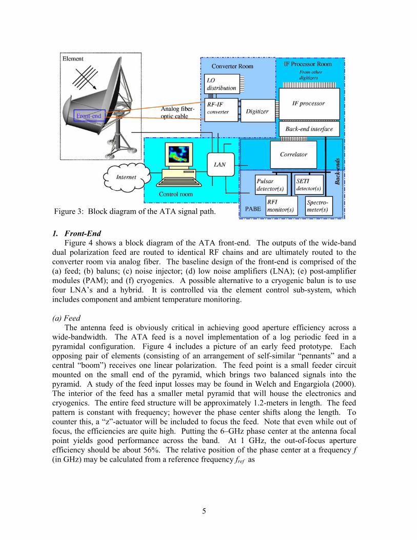
Figure 3 shows the signal path from one front-end to the back-ends. Also, properly speaking the ATA project itself extends only to the back-end interface and not to the back-ends themselves, which are provided by the users. The analog fiber links carry both polarizations of the full 0.5 – 11.2 GHz bandwidth back to the RF converter, where it is converted to four independent 1 GHz wide dual-polarization channels at L-band, then anti-alias-filtered and digitized. These channels are then passed through to the IF processor where they are further processed and sent to the back-ends. The signal path has four main sub-systems: (1) front-end, (2) RF converter, (3) IF processor, and (4) back-end interface.
Figure 2-b: Antenna blockage and cross-sectional view with feed and focus points.
5
1. Front-End
Figure 4 shows a block diagram of the ATA front-end. The outputs of the wide-band dual polarization feed are routed to identical RF chains and are ultimately routed to the converter room via analog fiber. The baseline design of the front-end is comprised of the (a) feed; (b) baluns; (c) noise injector; (d) low noise amplifiers (LNA); (e) post-amplifier modules (PAM); and (f) cryogenics. A possible alternative to a cryogenic balun is to use four LNA’s and a hybrid. It is controlled via the element control sub-system, which includes component and ambient temperature monitoring. (a) Feed
The antenna feed is obviously critical in achieving good aperture efficiency across a wide-bandwidth. The ATA feed is a novel implementation of a log periodic feed in a pyramidal configuration. Figure 4 includes a picture of an early feed prototype. Each opposing pair of elements (consisting of an arrangement of self-similar “pennants” and a central “boom”) receives one linear polarization. The feed point is a small feeder circuit mounted on the small end of the pyramid, which brings two balanced signals into the pyramid. A study of the feed input losses may be found in Welch and Engargiola (2000). The interior of the feed has a smaller metal pyramid that will house the electronics and cryogenics. The entire feed structure will be approximately 1.2-meters in length. The feed pattern is constant with frequency; however the phase center shifts along the length. To counter this, a “z”-actuator will be included to focus the feed. Note that even while out of focus, the efficiencies are quite high. Putting the 6–GHz phase center at the antenna focal point yields good performance across the band. At 1 GHz, the out-of-focus aperture efficiency should be about 56%. The relative position of the phase center at a frequency f (in GHz) may be calculated from a reference frequency fref as
Figure 3: Block diagram of the ATA signal path.
6
−≈∆
ffz
ref
1142 cm.
(b) Balun
The baseline design incorporates a cooled wide-band balun ahead of the LNA’s. Another possibility is to use a pair of LNA’s per polarization and combine them with a balun after amplification. Current modeling however indicates that the balun should exhibit similar loss to any transmission line, so having the balun precede the LNA is more appropriate in reducing complexity and the number of LNA’s. (c) Noise Injector
To calibrate and test the array, a common noise generator will be coupled into the signal path. The noise source is a spiral antenna external to the feed mounted on the primary surface.
(d) LNA
The availability of wide-band low-noise amplifiers (LNA) is a primary enabling technology making this instrument possible and is being pursued under contract with Sander Weinreb at JPL. This development utilizes InP HEMT MMIC devices that should achieve noise temperatures of about 12 K across much of the band if cooled to 80 K. The first realization achieved 20-25 K across the band; however improved modeling and design should be able to reduce the noise figure. A study of the power levels likely to be seen at the LNA is presented in DeBoer and Bower (2000).
Figure 4: Block diagram of the front-end.
7
(e) Post-Amplifier Module The post-amplifier module (PAM) conditions the signal for transmission on the optical
fiber link and places it on the link. This module will consist of variable gain; a high-pass filter to eliminate VHF (fc~300 MHz); a low-pass filter to reduce the noise power seen at the optical fiber driver (fc~11.5 GHz); and an equalizer to flatten the band. The ATA will very likely not implement phase switching at this point in the signal path.
The only economical way to bring the entire band back is via optical fiber (a microwave link would obviously not be appropriate). An optical fiber transmitter-receiver pair is under development under contract with Photonics Inc. of Burlington, MA, and will likely consist of an integrated Fujitsu laser/electro-absorption modulator, approximately one-kilometer of single-mode fiber and a detector.
Due to the high input-referred noise figure of the fiber link, it is one limiting component for the dynamic range, although the externally modulated laser is significantly better in this regard. Assuming a 41 dB noise figure and a +10 dBm 1-dB compression point and allowing the link to contribute 0.5 K to the overall system temperature, implies a dynamic range of about 22 dB. (f) Cryogenics Package
In order to achieve the requisite system temperature, the low noise amplifiers and baluns will likely need to be cooled to cryogenic temperatures. Furthermore, the cryogenics will need to be cheap and have a large mean time between failure (MTBF). A Pulse Tube Refrigerator (PTR) is being developed under contract with NIST and a proprietary compressor is being developed in-house. The cryogenics will likely produce temperatures around 60-80 K. 2. RF Converter
The RF converter accepts the analog optical fiber and produces several independent analog outputs, which are then digitized and processed. It consists of (a) the RF converter rack and (b) the LO source rack. The baseline design places 4 blocks of 16 per rack, for a total of 5.5 RF converter racks. The converter racks also house components of the LO distribution network. (a) RF Converter Rack
The RF converter rack consists of many RF converter boxes, many digitizer boxes, four 16-way LO distribution units, and one 4-way LO distribution unit. The RF converter box consists of the fiber detector to convert the entire band back to RF followed by a number of up/down converter chains to take some bandwidth at an arbitrary RF frequency and convert it to a band suitable for further processing. DeBoer (2001a) describes the RF converter box and includes one possible implementation. Possible frequency bands for the up/down converter are shown in Figure 5 and one possible implementation of a board that accepts optical fiber and produces four dual-polarization tunings is shown in Figure 6a.
8
The digitizer accepts the L-band output of the RFCB (8 per antenna), performs an I/Q
downconversion to baseband, selects an approximately 155 MHz band via an anti-aliasing low-pass filter, digitizes at a nominal 8 bits, serializes the I/Q signals onto a fiber and transmits it to the IF processor. The downconversion to baseband necessitates another LO be distributed in addition to the clock. Limited control logic will be implemented in the digitizer.
The 4-way LO distribution unit receives the six LO signals for the first two stages from
the LO source rack (4 LO1’s, 1 LO2 and 1 LO3) and splits it four ways to each of the 16-way LO distribution units, one per row of 16 converter and digitizer boxes. Figure 6b shows one implementation of the converter rack, with three of the four rows filled. At the bottom of the rack sits a power supply. The RF converter boxes plug into a backplane supported on an RF-tight septum while the digitizers plug in from the rear. The front and rear will likely both have an RF tight door. The net effect is 2 analog fibers in per antenna and 8 digital fibers out per antenna to the IF processor.
(b) LO Source Rack
The LO source rack will consist of one rack containing the individual synthesizers and appropriate distribution units to get the LO’s to the six RF converter racks.
Figure 5: Approximate frequencies for the RF-IF converter.
9
3. IF Processor
The IF processor (IFP) operates on the incoming digital data stream from the approximately 5600 bit streams (350 antennas × 2 polarization × 4 tunings × complex pairs). The IFP further splits each complex pair into separate paths to allow four independently steerable beams per tuning. These beams may then feed a phased-array back-end (PABE) and one per tuning will feed a correlator. The PABE beams are then tracked to steer the beam on the sky and summed.
The incident data streams are about 155 Mbps and then pass through an 8 tap FIR filter where the delay tracking is implemented. The data stream is then downsampled to about 100 Mbps and fed to the summing tree for the phased array beams and to the correlator. This oversampling/downsampling allows the delay tracking to be implemented across a relatively wide band with little error or aberration. More information on the IF processor may be found in D’Addario 2002a,b,c,d,e.
Mixer 1 BPF Mixer 2
Figure 6: One possible implementation of the RF converter box (a) and rack (b).
(a)
(b)
10
4. Back-End Interface The ATA exhibits an unprecedented amount of flexibility and will support multiple
back-ends simultaneously. The back-end interface consists of a back-end transmitter (BET)/back-end receiver (BER) pair to communicate with the individual back-ends. There are two broad categories of back-ends: the phased-array back-ends (PABE) and the correlator. Each PABE requires sufficient BET/BER pairs to process the number of beams it will handle (on the order of one to a few), while the correlator will require a relatively large number to transmit the data (on the order of 230).
Some of the planned PABE’s are: (1) SETI detectors, (2) pulsar processors, (3) astronomical spectrometers, and (4) RFI monitors. Note that these are not necessarily distinct—the spectrometer may be a reprogrammed pulsar processor, i.e. a programmable processor like a Beowolf cluster that can do many things. In addition, the back-ends will likely incorporate some system-wide RFI mitigation scheme(s).
More details of techniques to implement back-ends may be found in Bower (2000), D’Addario (2001), Rogers (2000), Urry (2000a), Urry (2000b), Welch and Dreher (1999), Welch (2000a), Welch (2000b), Wright (1998), Wright (2000). V. CONTROL
Figure 7 shows a rough schematic of the control (CTRL) system. Recall that although only one element is shown, there are in fact approximately 349 others. The control system has five conceptual sub-systems that correspond roughly to physical location and timing: (1) element; (2) converter; (3) processor; (4) environment; and (5) operations.
The demarcation between (a) the control of a given component and (b) the component being controlled will typically occur at the medium interface between the actual module and the point where the control signals are transferred onto some cable/wire. This will typically
Figure 7: Schematic of the monitor and command system.
11
be at some sort of edge connector, where everything within the module belongs to the appropriate system and everything that plugs into that connector is part of the control system. Ambiguous cases will be handled individually. 1. Element
The Element Control controls both the servo control and the front-end, i.e. all the things at the element.
The servo control will control the motors with feedback from the encoders to move the antennas and track sources in the sky. Given what should be a low backlash design, one outer PID loop should suffice to accurately point the antennas. The baseline design sends each element trajectory coefficients to track objects and need only be updated on the order of minutes. See DeBoer 2001c for a discussion of one trajectory scheme. One design of the ELC is shown in Figure 8.
Several options are being investigated for the processor, which will be some variant of an inexpensive embedded processor with sufficient I/O and Ethernet. The processor will interface to all control and monitor points at the element via other embedded microcontrollers and communicate back to the control room via the LAN.
The motor/encoder pair will drive the antennas and provide the pointing feedback. The PID loop will be closed at the local processor, which will also apply the pointing model. Another motor/linear encoder pair will adjust the focus of the antenna, the so-called “z-actuator”.
Figure 8: Schematic of the ELC. Blue denote parts of the signal path, green denotes part of the antenna and gray denotes site.
12
2. Converter The converter control sub-system is the simplest to deal with, in that the primary things
to control are just the four first LO’s, which are expected to be commercial synthesizers controlled via a GPIB interface. It is anticipated that there will be no control points within the RF converter boards, and minimal, low-rate monitor points, so as to minimize possible sources of RFI.
The RF power levels will be monitored in the digital processor, but will likely indicate a failure in the RF converter. A procedure with test fixtures is under development to aid in trouble-shooting the analog system.
3. Processor
Conversely, the processor control sub-system is probably the most complex, since it must deal with synchronous fast digital data streams and other user switching tasks and modes. The sub-systems controlled by the PRCC are the IFP and back-end interface, in addition to the phase switching of the first LO of the RF Converter, if implemented. 4. Environment
As part of the environmental MonCom, a weather station will be integrated to monitor the requisite meteorological parameters. Wind and appropriate logic based on wind speeds will be implemented. DeBoer (2000) details the expected wind conditions at Hat Creek Radio Observatory. Wind handling based on speed is as follows:
Winds ≤ 15 mph (98%ile sustained wind)1 Full accuracy pointing (2′) Winds ≤ 45 mph (98%ile daily gust max)1 Reduced accuracy pointing (20′) Winds ≤ 100 mph (“100 year wind”) Stow in wind-sock position Winds > 100 mph Damage may occur (euphemistically speaking) 1These specs are actually the purview of the ELC.
The atmosphere will also be monitored to correct for refraction pointing effects. Snow may require some action on the part of the control system so that the dishes don’t fill up with snow and exceed loading limits. Other adverse weather conditions requiring possible actions will also be monitored.
The temperature in important locations (primarily the converter and processor rooms) will also be controlled by this sub-system. VI. SITE
The facility will be located at the existing Hat Creek Radio Observatory in northern California, site of the BIMA millimeter array, which is in a process of relocation to a more southerly site. The layout and implementation of placing the stations and buildings must satisfy the local landlord and the US Forest Service, as well as our own aesthetic eye and to accommodate visitors. The site is comprised of (1) the array configuration, (2) infrastructure, and (3) RFI monitor. As stated above, the site is clearly not a system in the traditional sense, but serves as a collection area for many of the other important aspects of the array.
13
1. Array Configuration
The array configuration has been generated by optimizing for a Gaussian density of points in the uv plane (some preliminary studies using other methods may be found in Bock 2000b and Bock 2001b). Following the rationale of Bock (2001a), a naturally-weighted beamsize of 78'' (transit, declination 10 degrees) has been selected. The resulting array fits on the available land without severe shadowing: approximately 20% of samples in a two-hour observation of the Galactic Center will be affected. The minimum baseline is 10.8 m; the maximum baselines are about 950 m. The geographical constraints of the site constrain the optimization and set the magnitude of the near sidelobes, which will be below 1%. The far sidelobes are random with rms 0.3 %, set by the total number of antennas (350). A detailed topographical map and GPS-corrected aerial photograph are aiding in constraining the locations of the antennas, in addition to other geologic, geotechnical and geophysical surveys. 2. Infrastructure
The remaining infrastructure relates primarily to the buildings and trenching. The geology of the area consists of a lava flow that is at some points covered in soil, so the many miles of trenching will likely be problematic. 3. RFI Monitor
An RFI monitor (RFIM) has been installed at Hat Creek for the purpose of studying RFI from 100 MHz to 11 GHz. The monitor consists of two discone antennas covering 100 MHz - 3 GHz and 3 GHz - 11 GHz, respectively. The antennas are installed only one at a time atop a tower on lab 2. Both antennas have relatively flat frequency response over the given ranges and sensitivity primarily at the horizon. A broadband amplifier gives ~40 dB of gain. The signal is transmitted over coax into the laboratory. A 20 GHz spectrum analyzer under computer control is used to read back the signal. The system permits a variety of observations including sweep over a wide frequency range, fast retrieval of maxima and a peak hold mode. The PC runs linux and communicates with the spectrum analyzer through GPIB. VI. Software
The ATA will employ a distributed software architecture built up from many loosely-coupled client and server programs distributed over hundreds of processors. This system will be written primarily in the Java programming language, and leverages Java’s object model, threading, object serialization and class reflection to create a flexible control system. Processing nodes communicate over multiple Ethernet networks, and the system shall be scalable up to thousands of antennas.
In this system, each antenna comprises an autonomous node that may send or receive messages from the network. A half-dozen workstations in the control room provide the “head” of the control network, and dozens more processors are distributed for control of the IF electronics. All these nodes run Java and serve as front-ends for real-time processors lower in the hierarchy, if necessary. One guiding philosophy of the software system is to push any real-time processing requirements as low as possible in the hierarchy.
14
Related sets of resources are grouped logically and controlled by a hierarchy of server programs. The lowest level servers typically represent hardware devices. To run an experiment, higher-level servers and clients interconnect low-level servers. The requirement for multiple simultaneous users is met by a system of resource allocation and security that, typically, allows only one user to control a particular resource at a time (though many users may query resources for state). VII. CONCLUSIONS
The Allen Telescope Array is the first implementation of a large-N radio telescope and is being developed in an aggressive time-frame. The implementation must be clever and cheap in order to meet the required specifications within the allotted time and budget. It is a promising candidate for at least a portion of the Square Kilometer Array (SKA). The technology decision point for the SKA is 2005, about the time that the ATA will be completed.
The ATA is a scalable architecture. It may begin operation with a small subset of the full complement and may then be expanded beyond the original conception. The workings of Moore’s Law will drive ever-increasing functionality and performance in the digital hardware.
The Rapid Prototyping Array (RPA) is a current test array located near campus consisting of 7 3.6-meter mesh antennas. The primary uses of the RPA are as a software test platform and to examine issues related to RFI. Some documentation may be found in DeBoer (1999), Bock (2000a) and Harp and Ackermann (2001a, b).
Cataloging and tracking of the development for the ATA will implement the classification and naming scheme introduced above, and will be archived via standard web standards (primarily html and pdf) at
http://astron.berkeley.edu/~ddeboer/PARTS as a system called Putting All of the Resources Together Summary (PARTS). VIII. REFERENCES
Below are listed the memos of the ATA Memo Series as of April 4, 2002, both in alphabetical order by author and numerical order. 1. Arranged By Author 4 D. Bock, Drive Equations for the Rapid Prototype Array Antennas, May 15, 2000a 15 D. Bock, 50-antenna sample configurations for the Allen Telescope Array, November 1, 2000b 20 D. Bock, RAL Configuration Science Requirements for the Allen Telescope Array, March 26, 2001a 21 D. Bock, 350-Antenna Sample Configurations for the Allen Telescope Array, March 26, 2001b 9 G. C. Bower, Confusion, Dynamic Range and Array Size for the ATA, October 9, 2000 31 G. C. Bower, Application of Wiener and Adaptive Filters to GPS and Glonass Data from the Rapid
Prototyping Array, August 2, 2001a 37 G. C. Bower, Simulations of Narrow-Band Phased-Array Null Formation for the ATA, December 7,
2001b 22 L. R. D'Addario, Generalization of the Memoryless Corner Turner to the Non-Square Case, April 2, 2001a 24 L. R. D'Addario, Correlators: General Design Considerations, April 13, 2001b 27 L. R. D'Addario, Notes on Delay and Phase Tracking for the ATA, May 16, 2001c 40 L. R. D'Addario, Processing Architectures For Complex Gain Tracking, February 18, 2002a 41 L. R. D'Addario, ATA Digital Subsystem: Breadboard Circuits, February 18, 2002b 42 L. R. D'Addario, Performance Tests of Quadrature Downconverters, February 18, 2002c 43 L. R. D'Addario, Digital Processing Architecture of the ATA, February 18, 2002d
15
44 L. R. D'Addario, Digital Tests of Quadrature Downconverters, February 18, 2002e 3 D. R. DeBoer, The Rapid Prototype Array (RPA) Feed, November 22, 1999 5 D. R. DeBoer, The Winds of Hat Creek, July 11, 2000 16 D. R. DeBoer, The ATA Offset Gregorian Antenna, February 13, 2001a 18 D. R. DeBoer, The ATA RF-IF Converter, March 19, 2001b 33 D. R. DeBoer, Pointing/Trajectory Considerations for the ATA, September 19, 2001c 17 D. R. DeBoer and G. C. Bower, Effects of the Sun and RFI on the ATA Offset Gregorian Antenna, March
1, 2001 23 D. R. DeBoer and J. W. Dreher, A System Level Description of the ATA, April 6, 2001 8 F. Drake, The "SETI Efficiency" of Array Radio Telescopes, August 14, 2000 47 R. Ekers and G. C. Bower, Wide Field Imaging Issues for the ATA, April 4, 2002 35 G. Engargiola, Tapered Microstrip Balun for ATA Feed Development, November 26, 2001 45 G. Engargiola, Non-Planar Log-Periodic Antenna Feed for Integration with a Cryogenic Microwave
Amplifier, February 18, 2002 19 G. R. Harp and R. F. Ackermann, Mapping the Antenna Gain at the RPA, March 20, 2001a 26 G. R. Harp and R. F. Ackermann, RFI Survey at the RPA, May 2, 2001b 34 G.R. Harp and R.F. Ackerman, An FX Software Correlator at the RPA, November 12, 2001c 32 T. T. Helfer, Notes on Configuration for the ATA, September 18, 2001 36 D. A. Mitchell and G. C. Bower, Cancelling Satellite Interference at the Rapid Prototyping Array. A
Comparison of Voltage and Power Domain Techniques, December 7, 2001 12 A. E. E. Rogers, Array Processing Estimates for the ATA, November 2, 2000 10 W. L. Urry, The FFT as a Filter Bank, October 30, 2000a 14 W. L. Urry, A Corner Turner Architecture, November 17, 2000b 28 W. L. Urry, Delay and Fringe Rotation in Digital Beam Formers, May 16, 2001 39 W. L. Urry, The ATA Imager, January 28, 2002 38 S. Weinreb and N. Wadefalk, Noise Temperature and Gain of a Balanced Antenna Driving Differential
LNA's, January 7, 2002 2 W. J. Welch and J. W. Dreher, Beam Forming and RFI Elimination with the 1hT, September 20, 1999 7 W. J. Welch, Forming Nulls Toward Satellites, August 1, 2000a 13 W. J. Welch, Forming a Broadband Null with the ATA Using the Tree Algorithm, November 2, 2000b 25 W. J. Welch, An Offset Gregorian Optical System for the Allen Telescope Array, April 26, 2000a 29 W. J. Welch, Interactions Between the LP Feed and the Shroud and Reflectors, May 18, 2001b 46 W. J. Welch and D. C.-J. Bock, Broadband Amplitude Calibration of the ATA, March 28, 2002 6 W. J. Welch and G. Engargiola, Feed Input Losses, August 1, 2000 1 M.C.H.Wright, Astronomical Imaging with the One Hectare Telescope, December 1, 1998 11 M.C.H. Wright, Astronomical Imaging with the Allen Telescope Array – II, November 1, 2000 30 M.C.H. Wright, Astronomical Imaging with the ATA – III, May 22, 2001 2. Arranged By Memo Number 1 Astronomical Imaging with the One Hectare Telescope, M.C.H.Wright, December 1, 1998 2 Beam Forming and RFI Elimination with the 1hT, W. J. Welch and J. W. Dreher, September 20, 1999 3 The Rapid Prototype Array (RPA) Feed, D. R. DeBoer, November 22, 1999 4 Drive Equations for the Rapid Prototype Array Antennas, D. Bock, May 15, 2000a 5 The Winds of Hat Creek, D. R. DeBoer, July 11, 2000 6 Feed Input Losses, W. J. Welch and G. Engargiola, August 1, 2000 7 Forming Nulls Toward Satellites, W. J. Welch, August 1, 2000a 8 The "SETI Efficiency" of Array Radio Telescopes, F. Drake, August 14, 2000 9 Confusion, Dynamic Range and Array Size for the ATA, G. C. Bower, October 9, 2000 10 The FFT as a Filter Bank, W. L. Urry, October 30, 2000a 11 Astronomical Imaging with the Allen Telescope Array – II, M. Wright, November 1, 2000 12 Array Processing Estimates for the ATA, A. E. E. Rogers, November 2, 2000 13 Forming a Broadband Null with the ATA Using the Tree Algorithm, W. J. Welch, November 2, 2000b 14 A Corner Turner Architecture, W. L. Urry, November 17, 2000b 15 50-antenna sample configurations for the Allen Telescope Array, D. Bock, November 1, 2000b 16 The ATA Offset Gregorian Antenna, D. DeBoer, February 13, 2001a
16
17 Effects of the Sun and RFI on the ATA Offset Gregorian Antenna, D. DeBoer and G. Bower, March 1, 2001
18 The ATA RF-IF Converter, D. DeBoer, March 19, 2001b 19 Mapping the Antenna Gain at the RPA, G. R. Harp and R. F. Ackermann, March 20, 2001a 20 RAL Configuration Science Requirements for the Allen Telescope Array, D. Bock, March 26, 2001a 21 350-Antenna Sample Configurations for the Allen Telescope Array, D. Bock, March 26, 2001b 22 Generalization of the Memoryless Corner Turner to the Non-Square Case, L. R. D'Addario, April 2, 2001a 23 A System Level Description of the ATA, D. R. DeBoer and J. W. Dreher, April 6, 2001 24 Correlators: General Design Considerations, L. R. D'Addario, April 13, 2001b 25 An Offset Gregorian Optical System for the Allen Telescope Array, W. J. Welch, April 26, 2001a 26 RFI Survey at the RPA, G. R. Harp and R. F. Ackermann, May 2, 2001b 27 Notes on Delay and Phase Tracking for the ATA, L. R. D'Addario, May 16, 2001c 28 Delay and Fringe Rotation in Digital Beam Formers, W. L. Urry, May 16, 2001 29 Interactions Between the LP Feed and the Shroud and Reflectors, W. J. Welch, May 18, 2001b 30 Astronomical Imaging with the ATA – III, M. Wright, May 22, 2001 31 Application of Wiener and Adaptive Filters to GPS and Glonass Data from the Rapid Prototyping Array,
G. C. Bower, August 2, 2001a 32 Notes on Configuration for the ATA, T. T. Helfer, September 18, 2001 33 Pointing/Trajectory Considerations for the ATA, D. R. DeBoer, September 19, 2001c 34 An FX Software Correlator at the RPA, G.R. Harp and R.F. Ackerman, November 12, 2001c 35 Tapered Microstrip Balun for ATA Feed Development, G. Engargiola November 26, 2001 36 Cancelling Satellite Interference at the Rapid Prototyping Array. A Comparison of Voltage and Power
Domain Techniques, D. A. Mitchell and G. C. Bower, December 7, 2001 37 Simulations of Narrow-Band Phased-Array Null Formation for the ATA, G. C. Bower, December 7,
2001b 38 Noise Temperature and Gain of a Balanced Antenna Driving Differential LNA's, S. Weinreb and N.
Wadefalk, January 7, 2002 39 The ATA Imager, W. L. Urry, January 28, 2002 40 Processing Architectures For Complex Gain Tracking, L. R. D'Addario, February 18, 2002a 41 ATA Digital Subsystem: Breadboard Circuits, L. R. D'Addario, February 18, 2002b 42 Performance Tests of Quadrature Downconverters, L. R. D'Addario, February 18, 2002c 43 Digital Processing Architecture of the ATA, L. R. D'Addario, February 18, 2002d 44 Digital Tests of Quadrature Downconverters, L. R. D'Addario, February 18, 2002e 45 Non-Planar Log-Periodic Antenna Feed for Integration with a Cryogenic Microwave Amplifier, G.
Engargiola, February 18, 2002 46 Broadband Amplitude Calibration of the ATA, W. J. Welch and D. C.-J. Bock, March 28, 2002 47 Wide Field Imaging Issues for the ATA, R. Ekers and G. C. Bower ,April 4, 2002
17
Appendix A
SYSTEM SUBSYSTEMS SUB-SUBSYSTEMS/ASSEMBLIES Telescope (TEL) Alidade (ALD)