A. Laboratory Equipment Dept. of Food Processing Technology: 1. Tensile Strength Tester: Microprocessor based digital model, Capacity: 5-200KGF, Testing Speed: 12+/-3 MM/Min 2. Impact Tester 3. Bursting Strength Tester: Automatic digital microprocessor based 2-in-1 model for accurate testing of materials with lower burst value as well higher burst value,1-70 Kg/Cm 2 4. Tear Resistance Tester: Elmendorf type Tear Resistance Tester., Capacity:400KGF 5. Cobb Tester 6. Edge Crush Tester: Microprocessor based digital model with attachments for flat, edge & ring crush test. Capacity: 500Kg. 7. Pin Hole Detector: Table Top model, self illuminated chamber with one side Glass Top and Digital Counter. 8. Ultra Pure Water Purification System: Imported to produce up to 0.6 L/Min with integral pump, fully automatic system, Resistancy: 18.2MΩ.cm at 25 0 C, TOC<10, Particulates:<0.22 µm, with 10L reservoir attached. 9. Deep Freezer: Imported, capacity:256 L/220L (Inner), upright freeze, Temperature:-20 0 C, Re- circulated air cooling, frost free drawer system, auto defrost. 10. Vacuum Packaging machine: Table top model, vacuum pressure controller and indicator. 11. Baking Oven: 2 and 3 deck, temperature controller and timer for each deck. 12. Cake mixer: Planetary/spiral, Bowl can be tilted upside down, with temperature and speed controller, timer, 5Kg cap. 13. Dough Kneader: Bowl can be tilted upside down with temperature and speed controller, timer, 5Kg cap. 14. Vacuum Pump: Oil free, max. vacuum:600mm, Hg, max. pressure: 25 psi, motor rotation: 1450 rpm. 15. Can reforming unit: Electrical, for all can diameter.
Transcript
A. Laboratory Equipment Dept. of Food Processing Technology:
1. Tensile Strength Tester: Microprocessor based digital model, Capacity: 5-200KGF, Testing Speed: 12+/-3 MM/Min
2. Impact Tester3. Bursting Strength Tester: Automatic digital microprocessor based 2-in-1
model for accurate testing of materials with lower burst value as well higher burst value,1-70 Kg/Cm2
4. Tear Resistance Tester: Elmendorf type Tear Resistance Tester., Capacity:400KGF
5. Cobb Tester6. Edge Crush Tester: Microprocessor based digital model with attachments
for flat, edge & ring crush test. Capacity: 500Kg.7. Pin Hole Detector: Table Top model, self illuminated chamber with one
side Glass Top and Digital Counter.8. Ultra Pure Water Purification System: Imported to produce up to 0.6
L/Min with integral pump, fully automatic system, Resistancy: 18.2MΩ.cm at 250 C, TOC<10, Particulates:<0.22 µm, with 10L reservoir attached.
9. Deep Freezer: Imported, capacity:256 L/220L (Inner), upright freeze, Temperature:-200 C, Re-circulated air cooling, frost free drawer system, auto defrost.
10. Vacuum Packaging machine: Table top model, vacuum pressure controller and indicator.
11. Baking Oven: 2 and 3 deck, temperature controller and timer for each deck.
12. Cake mixer: Planetary/spiral, Bowl can be tilted upside down, with temperature and speed controller, timer, 5Kg cap.
13. Dough Kneader: Bowl can be tilted upside down with temperature and speed controller, timer, 5Kg cap.
15. Can reforming unit: Electrical, for all can diameter.16. Can flanging machine: For all can diameters.
B. Equipment Project work, Dept. of Physics
1. Magnetron: Pulsed co axial, X-band, power greater than 80kW, Air cooled.2. Power supply compatible with the Magnetron: Include the current, voltage and
mounting arrangement for the magnetron (Highly stabilized and shielded)3. Power meter: In X–band (Measurement of high power)4. Sensor: Compatible with the power.5. Accessories: High power circulators, wave guides with choke flanges, high power
loads, adapters(HP), frequency meter, connectors, high precision attenuators etc.(Capable in handling high power in X-band range)
6. Electromagnet with Gauss meter: Uniform about pole area of 6CM2, ltesla at pole distance of 2CM.
7. Power Meter: Upto atleast 18GHz (Agilent-HP)8. Sensor: Average power compatible with power meter.(Agilent-HP)
C. Equipment-Dept. of Mechanical Engineering.
1. CNC PRODUCTION LATHE: Specifications:Make: MTABCapacity:Maximum Turning Diameter 160mmMaximum Boring Length 20mmDistance between centre 250mmMax. turning length 130mmBar capacity (diameter) 25mmTraverse:Travel on X-axis 100mmTravel on Z-axis 250mmRapid Traverse X-axis 10m/minRapid Traverse Z-axis 10m/minSwing over bed 220mmSpindle motor 5hpThe machine should be FMS compatible.Turret:8 stations/programmable turretMaximum Boring Bar Dia 20mmTool Cross section: 12x12
CNC Control Options:Fanuc OiT Mate with servo MotorsSiemens 8020D Controller
2. ARC WELDING MACHINE: Specifications: Primary voltage (volt) 380/415Phase 1-3Rating (KVA)Continuous 7-30Maximum 13-45Open circuit voltage (volt) 50-100Open arc voltage (volt) 20-45Welding current range (ampere) 30-600Welding electrode range (mm)Minimum 1.5-2.5Maximum 4-6Cooling air
3. UNIVERSAL MILLING MACHINE: ALONG WITH ALL STANDARD ACCESSORIES
Make: HMT/BATLIBOI/BFW
Specification
specifications UNIT
Table width mm 400
Table length mm 1400
Longitudinal Traverse mm 1000
Ram Traverse mm 450
Vertical Traverse mm 450
Feed rate longitudinal axis mm/min 10-1800
Feed rate cross axis mm/min 10-1800
Feed rate vertical axis mm/min 2.5-450
Rapid rate longitudinal axis m/min 4
Rapid rate cross axis m/min 4
Rapid rate vertical axis m/min 1
Spindle power kw 11
Spindle speeds rpm 40-2000
Spindle taper ISO 40/ISO50
SPECIAL ACCESSORIES FOR UNIVERSAL MILLING MACHINE:
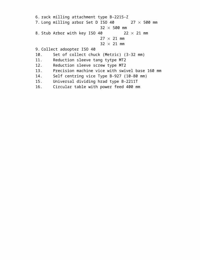
1. Coolant equipment2. Machine lamp3. Universal Milling Head4. Vertical Milling Head type B-3501-35. Slotting attachment type B-2215-s6. rack milling attachment type B-2215-Z7. Long milling arbor Set D ISO 40 27 500 mm
32 500 mm8. Stub Arbor with key ISO 40 22 21 mm
27 21 mm32 21 mm
9. Collect adoopter ISO 4010. Set of collect chuck (Metric) (3-32 mm)11. Reduction sleeve tang tytpe MT212. Reduction sleeve screw type MT213. Precision machine vice with swivel base 160 mm14. Self centring vice Type B-927 (10-80 mm)15. Universal dividing hrad type B-2211T16. Circular table with power feed 400 mm
4. HORIZONTAL MILLING MACHINE: ALONG WITH ALL STANDARDACCESSORIES
Make: BFW/ BATLIBOI/HMT
Specification
Table Size 1350 x 320T-slots No./ Width/ CD. mm 3/ 14/ 63Traverses Longitudinal mm 800 Cross mm 260Vertical mm 390/400Milling spindle front bearing Ø mm 85Spindle taper ISO 40Speed range rpm 45-2000No./ progression 12/ 1.4No. of Feeds Nos. 18Feed range (Progression 1.25)Longitudinal mm/ min 14-900Transverse mm/ min 14-900Vertical mm/ min 4-250Rapid TransverseLongitudinal mm/ min 4000
Transverse mm/ min 4000
Vertical mm/ min 1000
Milling spindle motor kW 5.5Feed motor kW 1.5Max. safe weight on the table kg 400Weight/ Nett (approx.) kg 2200
SPECIAL ACCESSORIES FOR HORIZONTAL MILLING MACHINE:1. Coolant equipment2. Machine lamp3. Long arbor ISO 40 27 500 mm
32 500 mm4. Stub arbor 22 21 mm
27 21 mm32 21 mm
5. Collect adopter ISO 406. Set of collets (3-32) mm7. Reduction sleeve IS 5927 MT1 ISO 408. Universal Indexing Head with self cetring chuck (Brown & Sharp type)9. Machine vice (Fixed)10. Machine Vice (Universal)11. Rotary table12. Self Centring vice B-927 (10-80 mm)13. Set of change gear (24-100 teeth)
14. Tail stock
5. VERTICAL MILLING MACHINE: ALONG WITH ALL STANDARDACCESSORIES
Make: BFW/BATLIBOI/HMT
Specification Overall size (L x W) mm 1555 x 315Clamping area mm 1350 x 315T-slots No./ Width/ CD. mm 3/ 14/ 63Swivel range of table to both sides degrees -
Longitudinal movementAutomatic mm 800Manual mm 830Transverse movementAutomatic mm 230Manual mm 260Vertical movementAutomatic, mm 400Manual ,mm 420
SpindleQuill stroke, manual, mm 70
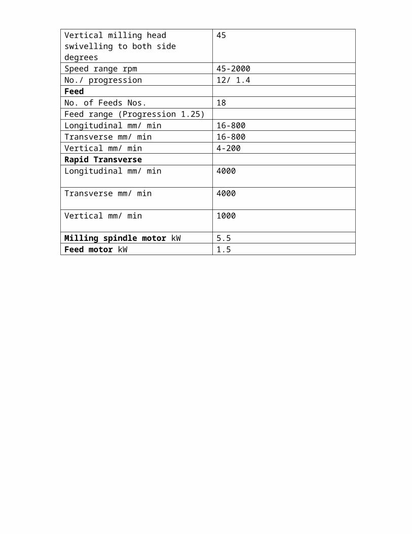
Milling spindle front bearing Ø mm 85Spindle taper ISO 40Vertical milling headswivelling to both side degrees
45
Speed range rpm 45-2000No./ progression 12/ 1.4FeedNo. of Feeds Nos. 18Feed range (Progression 1.25)Longitudinal mm/ min 16-800Transverse mm/ min 16-800Vertical mm/ min 4-200Rapid TransverseLongitudinal mm/ min 4000
Transverse mm/ min 4000
Vertical mm/ min 1000
Milling spindle motor kW 5.5Feed motor kW 1.5
SPECIAL ACCESSORIES FOR VERTICAL MILLING MACHINE:
1. Coolant equipment2. Machine lamp3. Stub Arbor with key ISO 40 22 21 mm
27 21 mm32 21 mm
4. Collect adoopter ISO 405. Set of collect chuck (Metric) (3-32 mm)6. Reduction sleeve tang tytpe MT27. Reduction sleeve screw type MT28. Precision machine vice with swivel base 160 mm9. Self centring vice Type B-927 (10-80 mm)10. Universal dividing hrad type B-2211T11. Circular table with power feed 400 mm
6. SHAPING MACHINE ALONG WITH ALL STANDARD ACCESSORIES
Make: AARPEE
Specification
Length of the ram stroke, mm 915Length of ram without tool slide, mm 1740Maximum distance from table to ram, mm 521Minimum distance from table to ram, mm 140Horizontal traverse of the table, mm 870Vertical traverse of the table, mm 390Angular movement of the table on either side, degree
fixed
Working surface of the table, mm 457915Maximum size of the tool shank accommodated, mm
3821
Maximum vertical travel of tool slide, mm 200Maximum swivel of tool head, mm 60I, 60rLength of main slide, mmNumber of ram speedsRange of ram speed, stroke per minute 12 25 40 67Range of table feed per stroke of ram, mm 0.229-0.687Range of tool head feed Hand feedMain drive motor, kw 5hpSpeed, RPM 960
SPECIAL ACCESSORIES
1. Key way cutting attachment2. Machine light3. Auto tool lifter
7. SURFACE GRINDING MACHINE ALONG WITH ALL STANDARDACCESSORIES
Make: Praga Tools
Specification
Table Work area, mm 455 x 150 – 600 x 200Longitudinal traverse, mm 152-650Cross traverse, mm 101-228
FeedsTable longitudinal speeds, m/min 1.5 to 18Cross feed per stroke at each reversal, mm 0.175-1.75
Wheel headVertical movement, mm 101-305Speed of wheel, rpm 2800-4000Size of the wheel, mm 178 x 13 x 32 – 203 x 20 x 25
1. Magnatic chuck 600 200 mm2. Diamond holder and diamond for magnaticc chuck3. Diamond for std. Table mounted wheel truing attachment4. Diamond for Radius and angular wheel forming attachment.5. Dust exhaust equipment6. Electrical pump and coolant fitting UV-61007. lighting equipment with low volt transformer8. static wheel balancing unit 2101-0019. universal 3 way swiveling vice admits work 65 mm width of jaw 100 mm x 1310. Sine Vice.11. 90 vice12. Grinding Wheel (Soft and hard grade)13.
8. PEDESTAL GRINDING MACHINE ALONG WITH ALL STANDARD ACCESSORIES
Specification
Size of grinding wheel, mm 150 x 20 x 15 – 1000 x 406.4 x 200Wheel center distance, mm 600-1500Base to the center line, mm 810-910Diameter of spindle in bearings, mm 35-100No of motors 1-2Power of motor, kW 1.5-15Speed of motor, rpm 450-2250Number of speeds 2-3Net weight, kg 27-1150
Special accessories:
1. Grinding wheel Dresser
2. Coolant equipment
9. UNIVERSAL TOOL AND CUTTER GRINDING MACHINE: ALONG WITH ALL
STANDARD ACCESSORIES
Make: HMT (with power rise and fall of wheel head)
Specifications :Centre height mm 130Swing mm 280Swing with raising block mm 370Admit between tailstock centres mm 760Admit between work head & tailstock centre mm 615Max. job weight for cylindrical grinding
kg 15
Longitudinal travel of table mm 510Clamping area mm 980x140Cross traverse mm 250Tailstock taper MT2Total power kW 3
Special Accessories:
1. Indexing unit with one indexing ring having 24 Dvn2. 3-speed work head for cylindrical grinding (.18kw)3. Right hand tailstock with center4. 3-jaw chuck dia 160 mm5. Draw bar for above chuck6. Two-jaw steady7. Wheel guard with bracket8. Grinding wheel 200/20x32 A46 K5V Eqv9. Universal vice for surface grinding10. Attachment for grinding of end relief disk cutter11. Gear milling cutter grinding attachment with 3 bushes12. Centre attachment for long reamer13. Attachment for grinding carbide tipped tools14. Twist drill sharpening attachment dia 5/25 mm 15. Dust exhausting device16. Water cooling device 17. Wheel shoulder dressing attachment18. Radius truing attachment 19. Dressing diamond 1 ct. with par. shank dia 12 x 15020. Machine lamp 220 volts (without bulb)
21. Set of spare
10. HIGH SPEED PRECISION LATHE :
Make: HMT along with all standard accessories
Specifications Height of centers mm 260Swing over bed mm 575Swing over cross slide mm 350Swing in gap (optional) mm 800Distance between centers mm 2000 Spindle Nose / Bore mm A2-6* / 53Spindle Speed range rpm 16 from 40-2040 forward 7 from 60-1430
reverse Spindle power kW 11Feed range (longitudinal) mm/rev 60 from 0.04-2.24Feed range (cross) mm/rev 60 from 0.02-1.12Lead screw pitch mm 6Metric threads mm 48 from 0.5-28Inch threads tpi 60 from 56-1Module threads mm 40 from 0.25-14Diametral pitch (optional) mm 43 from 112-2Tailstock sleeve travel mm 200Main motor power kW 7.5 (std.) / 11.0 (opt.)
Special Accessories
1. Collect chuck with collets (23 piece)2. Machine lamp for 24 volts (without lamp)3. Swarf tray coolant equipment4. Splash guard5. Star-Delta starter6. Steady rest 8-145 mm7. Change gear for cutting modules and diametral pitch (4 nos. change gear and one
name plate)8. Precision face plate dia 355 mm9. 3-jaw self centring chuck dia 250 mm10. Taper turning attachment11. Hydraulic chuck with 250 mm (4 jaw)12. Hydraulic power pack13. Rotating type hydraulic cylinder OSP-12014. Multicut tracer (Manual) for C. D. 2000 mm15. Precision 3-jaw self centring chuck with hardened 16. Jaw-reversible for internal & external chucking dia 250 mm17. Universal Face Plate dia 550 mm
18. Follower rest 8-80 mm19. Longitudinal stop20. Stop roll
11. PILLAR DRILLING MACHINE ALONG WITH ALL STANDARD ACCESSORIES Make: EIFCO
Specification
Drilling Diameter in steel, mm 30Spindle travel, mm 220Number of Spindle speeds 6Range of speeds, rpm 3000Feed values, mm/rev 1.8-2Main motor, KW 1-1.2Work table overall dimensions, mmmm 450400Diameter of column, mm 300-350Max. Distance between column to spindle center, mm
250-300
Net weight, Kg 800-1000Overall dimension(lengthwidth),mm 800550
Software architecture The Software should have a single database structure. Parametric feature based models should extend throughout all aspects of product
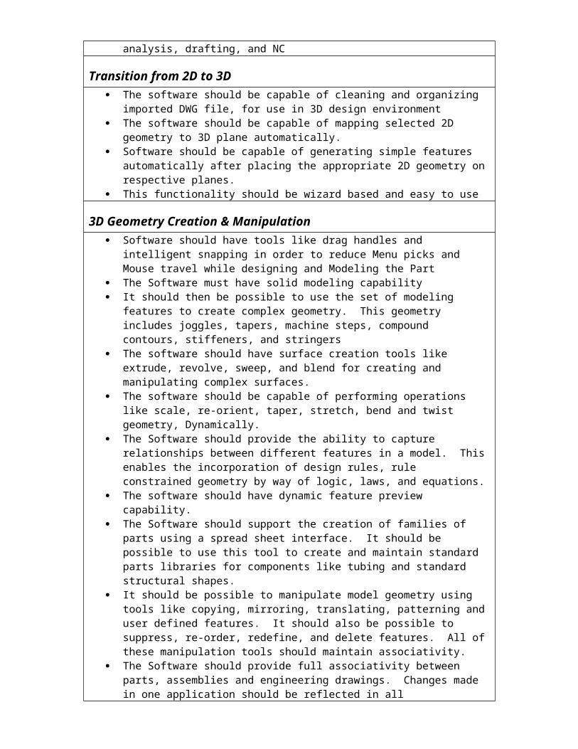
development including modeling, analysis, drafting, and NC
Transition from 2D to 3D The software should be capable of cleaning and organizing imported DWG file, for use
in 3D design environment The software should be capable of mapping selected 2D geometry to 3D plane
automatically. Software should be capable of generating simple features automatically after placing
the appropriate 2D geometry on respective planes. This functionality should be wizard based and easy to use
3D Geometry Creation & Manipulation Software should have tools like drag handles and intelligent snapping in order to reduce
Menu picks and Mouse travel while designing and Modeling the Part The Software must have solid modeling capability It should then be possible to use the set of modeling features to create complex
geometry. This geometry includes joggles, tapers, machine steps, compound contours, stiffeners, and stringers
The software should have surface creation tools like extrude, revolve, sweep, and blend for creating and manipulating complex surfaces.
The software should be capable of performing operations like scale, re-orient, taper, stretch, bend and twist geometry, Dynamically.
The Software should provide the ability to capture relationships between different features in a model. This enables the incorporation of design rules, rule constrained geometry by way of logic, laws, and equations.
The software should have dynamic feature preview capability. The Software should support the creation of families of parts using a spread sheet
interface. It should be possible to use this tool to create and maintain standard parts libraries for components like tubing and standard structural shapes.
It should be possible to manipulate model geometry using tools like copying, mirroring, translating, patterning and user defined features. It should also be possible to suppress, re-order, redefine, and delete features. All of these manipulation tools should maintain associativity.
The Software should provide full associativity between parts, assemblies and engineering drawings. Changes made in one application should be reflected in all applications.
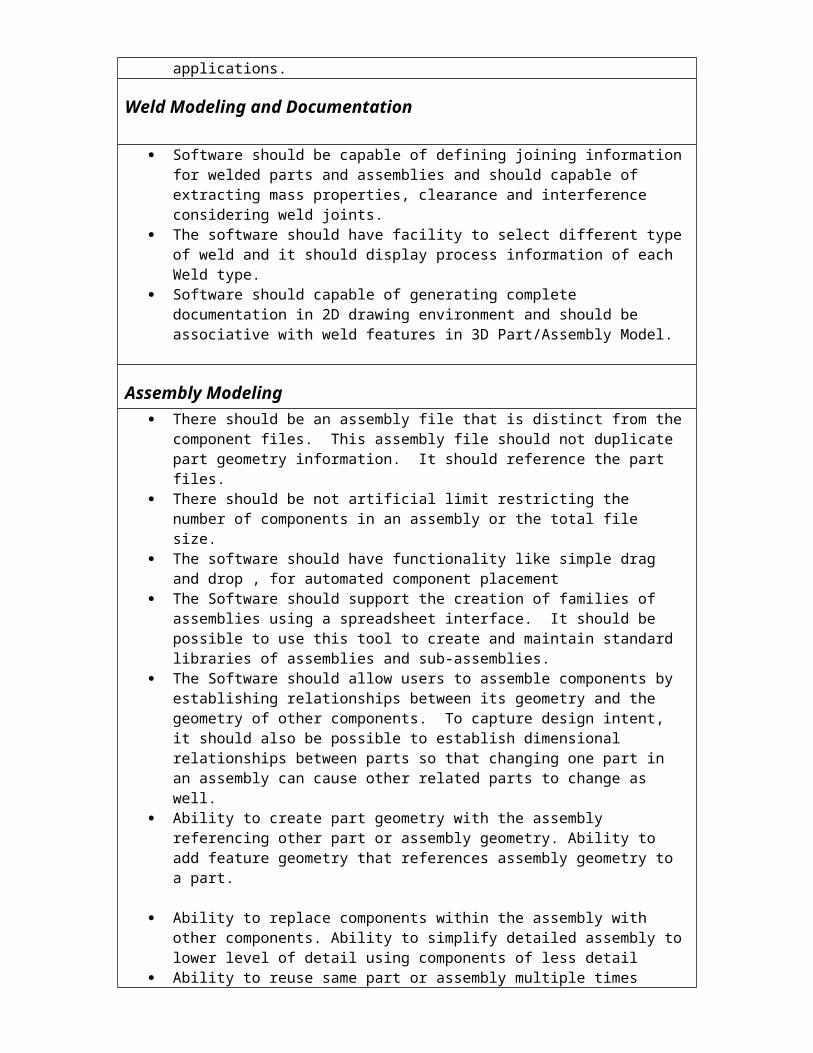
Weld Modeling and Documentation
Software should be capable of defining joining information for welded parts and assemblies and should capable of extracting mass properties, clearance and interference considering weld joints.
The software should have facility to select different type of weld and it should display process information of each Weld type.
Software should capable of generating complete documentation in 2D drawing environment and should be associative with weld features in 3D Part/Assembly Model.
Assembly Modeling There should be an assembly file that is distinct from the component files. This
assembly file should not duplicate part geometry information. It should reference the part files.
There should be not artificial limit restricting the number of components in an assembly or the total file size.
The software should have functionality like simple drag and drop , for automated component placement
The Software should support the creation of families of assemblies using a spreadsheet interface. It should be possible to use this tool to create and maintain standard libraries of assemblies and sub-assemblies.
The Software should allow users to assemble components by establishing relationships between its geometry and the geometry of other components. To capture design intent, it should also be possible to establish dimensional relationships between parts so that changing one part in an assembly can cause other related parts to change as well.
Ability to create part geometry with the assembly referencing other part or assembly
geometry. Ability to add feature geometry that references assembly geometry to a part.
Ability to replace components within the assembly with other components. Ability to simplify detailed assembly to lower level of detail using components of less detail
Ability to reuse same part or assembly multiple times within an assembly without recreating files
Ability to quickly create multiple explosions automatically Ability to add offset lines Ability to quickly modify explosions by dragging and dropping Automatic tracking of BOM information in real time Different methods to verify fit of components with assembly Mechanism to analyze tolerance stack up in an assembly Automatic update of changes made to components to higher level assemblies via both
dimensions and geometry update
Any changes made to the assembly should automatically update any associated engineering drawings
Ability to remove a component from the assembly without requiring it to be deleted and reassembled later
The software should be capable of representing Parts or Sub-assemblies in order to minimize utilization of computer resources and to provide only required data to User while working with assemblies.
Software should be capable of designing large & complex assemblies by using Tools that supports top down design approach
Software should be capable of documenting assembly Processes
Imported Data cleaning and repair The software should have functionality to speed up the cleaning and data fixing
activities while working on imported 3D data
Quality Check Tools The software should have functionality to check Parts, Assemblies and Drawings
against pre-defined Modeling and detailing Practices and standards
Mechanism Design Integrated Mechanism Design capabilities that could define mechanism and even
convert assembly into mechanisms Animate mechanism assemblies through interactive dragging and user-defined motions Functionalities to detect Interference, clashes during animation and calculate
interference volume at any time during the motion Software should be capable of simulating reactions to acceleration forces & weight of
moving components with the ability of incorporating springs, dampers, motors, friction, gravity and other dynamic influences
Sheet Metal Modeling The Software should be able to create accurate solid models of all sheet metal
geometry. It should provide flexible tools to create sheet metal walls and other sheet metal geometry including cuts, punches, rips, twists and forms. It should be possible to create this geometry in both the bent and flat states.
The Software should create accurate solid representations of walls including the deformation due to bends. This includes the ability to create cuts that penetrate bend regions, and bends that penetrate cut regions
The Software should provide flexible tools that enable the accurate calculation of the developed length of unbent walls. These tools should include the use of default and customized bend tables, specialized equations, and Y-factors
The Software should be able to create automatic and manual bend relief’s. The Software should let the user specify a bend order for sheet metal parts. It should be
possible to document this bend order in drawings and use the bend order to simulate the bending process.
The Software should be able to convert parts with non-uniform wall thickness (solid parts) to sheet metal parts. Similarly, the Software should be able to convert surface models into sheet metal parts with uniform wall thickness.
Detailed Drawing Generation Any changes made to the part or assembly should automatically be updated in the
drawing. This includes updating of any views as well as any annotations in the drawing After one general view has been placed, the software should be able to create any
additional projection view without specifying any orientation constraints Mechanism to create different types of views including projection views, detailed
views, partial views, etc. Ability to quickly place and update location of views. Have scale for different views
and the sheet. Display models in hidden line, wire frame. Ability to customize display of different entities in individual views.
Drawing created using the package should conform with AMSE Y14.5 Different types of annotation should be created in the drawing. Notes, symbols, etc.
should update as the geometry changes Ability to add changeable information in a drawing in the form of notes. Information
from the model should be readily accessible in the notes Ability to have a library of notes and symbols that can be re used minimizing time for
creation of similar annotation in user defined format Have library of ANSI standard drawing symbols readily available for inclusion in
drawings. Different types of symbols such as electrical, piping, heating or welding. The symbols should be user modifiable.
Create engineering drawing of whole assemblies or parts. All relevant detail should be viewable in the drawing. Drawings should also be show whole assemblies or simplified versions of the assemblies or parts on the same sheet
Ability to show as many models as needed on the same sheet. Can be parts or assemblies.
Ability to create and reuse standard drawing formats. Formats should be able to access drawing and part information to automate title block definition.
Easy to use geometric tolerancing within the drawing Ability to create drawing tables (grid of row and columns) and include it drawing,
formats and conceptual layouts. Ability to reuse tables. All attributes of the table such as number of columns and rows should be easily modifiable
Ability to customize engineering drawing environment. Options such as text parameters, arrow length and style should be controlled from a central location. Ability to create and reuse a standard setup
Mechanism to compare two similar engineering drawings for differences in dimensions or topology
Provides tools to markup a single engineering document without affecting the document Perform markups in a collaborative environment. View markups simultaneously or
individually Tools for the addition of general drafting entities for further customization of the
drawing Ability to export and import engineering drawings via DXF, DWG, IGES, VDA and
SET files
Technical Publication
The Software must be able to automatically generate bill of material information.
The Software should support Microsoft’s Object Linking and Embedding so that models can be pasted into OLE compliant applications. These graphics can then be used to create technical presentations and documentation.
The Software should provide an interface to the World Wide Web that enables the export of parts, assemblies, and process plans to complete Web pages using standard HTML, VRML, CGM, and JPEG formats and Java applets. Exported information can then be viewed on the Internet or an intranet using standard Web browsers
Design sensitivity StudyGraphical feedback
Software should be capable of applying multiple objectives to a design scenario and then carry out feasibility studies by creating number of virtual prototypes as needed to match the requirements
Software should deliver the results in easy to read graphical format to choose the optimum design
Cabling Design Software should be capable of Automatically route wires and cables in 3D space and it
should logically reference diagram schematic data Software should be capable of selecting preferred terminators, plugs, and wire strip length Automatically Software should capable of automatically generating Customizable BOMs, wire lists, and flattened harnesses
Piping Design Software should be capable of Automatically route pipelines in 3D space It should also
capable of reading fluid diagrams electronically and use the information to interactively create 3D pipelines
Software should be capable of evaluating pipelines for manufacturability and interference
Reverse Engineering Software should be capable of reading large sets of scanned data containing up to
millions of points & should support various industry standard Software should be capable of filtering the scanned data in order to optimize the cloud
point data to prepare digital mockup. It should be capable of automatically fitting digital curves and surfaces to selected raw reference points in the scanned data and gives flexibility to the user to modify the digital data dynamically using various control points
The digital Prototype generated using reverse engineering techniques should be further used for design modifications, generating manufacturing drawings
Photo-rendering and Animation The software should be able to create photo-realistic images that include effect of
shadows, reflection, transparency and texture mapping.
The software should be capable of quickly creating animation of assembly/disassembly with an option of including mechanisms in animation.
Computer aided Manufacturing (CAM)
Requirement / Capability
Complete mold design Software should be capable of designing mold cavity geometry with specific functions
like automated parting line & parting surface creation, ability to evaluate draft, undercut and thickness as well as projected area, facility to compensate for shrinkage iso-tropically and ansio-tropically, functionality to automatically split the mold into inserts, functionality to create specific features such as runners & Gates.
Software should have library /catalog of all major mold component suppliers – Metric & English
Software should have process driven User Interface for creating customized moldbase with facility of quick preview while developing moldbase It should be able to create moldbase drawings, holecharts & BOM automatically
Manufacturing Solutions (Lathe /machining canter/EDM) Software should support NC programming for 2.5 axis prismatic milling , up to 5 axis
machining ,multi axis turning , mill/turn machining & 4 axis wire EDM Software should be capable of viewing and managing manufacturing process in a table
environment with NC process manager Software should be capable of Capturing and re-using various machining practices to
streamline and standardize manufacturing methodologies. It should be capable of optimizing finishing tool paths for surface machining
Manufacturing Solutions (for sheet metal components) Software should support NC programming for turret punch presses, contouring
laser/flame machines, nibbling and shearing. It should support automatic flat pattern development of sheet metal components with bend
allowances, automatic punch tool selection and part nesting
Post Processor Development Software should be capable of developing Post Processors for all Industry standard
Software should be able to perform Static analyses to compute stresses and displacements, including contact non-linear effects, Large deformation non-linearity effects in static analyses, Pre-stress static and pre-stress modal analyses, including spin softening and stress stiffening effects, Modal solutions to compute both free and constrained natural frequencies, Vibration analyses including dynamic frequency, time, random, and shock.
In addition it shoul be able to support & perform following capabilities
Buckling analysis capabilities to compute critical buckling load factors , Steady-state thermal analyses to evaluate a model's reaction to applied thermal loading
and boundary constraints , Non-linear transient thermal analyses to model time-varying thermal events such as the
time required for a model to reach a steady state
2D idealized model types including plane stress, plane strain, 2D plate, 2D unit depth, and axisymmetric
Software should have tools/libraries to quickly build simulation models such as Weld connections, including spot, end, and perimeter; Advanced spring and mass idealizations, Rigid connections, Advanced shells with properties such as laminate lay-ups, Engineering loads and constraints such as bearing loads and cyclic symmetry constraints, Isotropic, orthotropic, and anisotropic materials support,
Design Optimization Software should be able to perform local as well as global sensitivity studies hat let the
engineer evaluate the impact of individual changes on design performance Software should be able to achieve the optimum model profile based on a combination
of design parameters, such as model dimensions and property values Software should have a generic optimizer interface that allows the use of external
design optimization systems
Fatigue Prediction Tool Software should have capability to predict & improve the fatigue performance. It should
be able to calculate result quantities, such as life, damage and factor of safety, It should be able to define and track local and global measures of results quantities for sensitivity and optimization design studies
System Requirements The software should support following Operating systems Windows XP, Windows 2000. Linux HP-US, IRIX & SUN Solaris The data should be compatible across all the platforms and software should work in a
heterogeneous network comprises of various Operating systems like Unix, Linux & Windows XP/2000
Licensing Requirement The License of the Software should be server based with soft License code The licensing of the Products should support 100 concurrent uers for each of the
functionality as stated in specification A, B, & C The license (perpetual) for 100 Concurrent users include free updates, upgrades and
bug fixing at no extra charge
Other Terms & Conditions Vendor should be an ISO 9001: 2000 certified Organization Vendor should be either developer of the Product or first level Reseller with
sufficient experience in sales ( to minimum 30 educational Institutes in India) execution & support of the proposed Product in India.
Vendor must produce list of such 30 Educational Institutes where Vendor has sold
the offered product.
D. Equipment B. Tech( Dept. of Electronics & Communication Engineering)
1. A.M. Transreceiver kit Specification: DSB/SSB, Modulator/Demodulator, Amplifier, Filter, Transmitting antennas, Detector, Standard Carrier signal etc.
2. F.M. Transreceiver kit Specification: DSB/SSB, Modulator/Demodulator, Amplifier, Filter, Transmitting antennas, Detector, Standard Carrier signal etc.
3. TDM Pulse Amplitude Modulation/Demodulation Training kitSpecification: Crystal oscillator, Analog signal generator, Variable sampling frequency/duty cycle, Filters etc.
4. PAM/PPM/PWM Modulation & Demodulation training kit Specification: Variable sampling/pulse frequency, Voice-commn, Filter, Amplifier/Detector etc.
5. ASK/FSK modulation & demodulation Training kitSpecification: On-board data simulator, synchronized 3 carrier sine wave, Test points etc.
6. PSK & QPSK modulation & demodulation trainer kitSpecification: On-board data simulator, synchronized 3 carrier sine wave, Test points etc.
6. Oscilloscope Specification: (DC-200 MHz, Color/Mono LCD or TFT screen, Dual channel with 4k memory per channel, Built-in mathematical functions, FFT/USB interface, Digital filters, Auto set and calibration functions, Auto measurement etc.)
7. Function generator Specification: Range: 0.2 to 2Mhz, Sine, square, triangular, Pulse, Ramp, TTL output with 20V Vpp
8. Multiple Power supply Specification: variable up to 30 volts, Low ripple, good load/line regulation, short circuit protection etc.
Following Linear displacement transducers to be mounted on the test rig: i) Linear variable resistor ii) Variable inductoriii) Variable area capacitor iv) Linear variable differential transducer (LVDT)v) Variable distance capacitor & Strain gaugevi) Manual Assignments, covering the Transducers Kits and including relevant
theory and practical information.
2. Thermal Transducers Trainer Kit Specifications: Following thermal devices and a heat bar assembly with temperature gradient should be mounted:
i) Thermistor ii) Thermal reed relayiii) Platinum resistance iv) Bi-metallic switch n Thermocouplev) Manual Assignments, covering the Transducers Kits and including relevant
theory and practical information.
3. Optical Transducers Trainer Kit Specifications: A light source and the following sensors should be mounted:
i) Photoconductive cell ii) Photodiode n Phototransistoriii) Manual Assignments, covering the Transducers Kits and including
relevant theory and practical information.
4. Sensor Signal processing Trainer kit : Specifications:
Following instrumentation and signal conditioning circuitry should comprise:i) Wheatstone Bridge ii) Oscillatoriii) Operational Amplifier iv) Discriminator Power Amplifier
5. Servo Control Trainer Kit:Specifications:
The system should consists of three main units: Mechanical Unit: Input and output potentiometers, motor, tacho-generator, absolute and incremental encoder and waveform generators. Signal Unit: Error amplifier, Optional additional time constant. Variable gain and velocity feedback. Single, two term or full PID control. Digital Unit: Encoders should provides access to PC interfacing with ADC & DA linear or PWM motor drive, LED display. Feedback software supports for both the Analogue and Digital units.
6. DC Servo Control Trainer Kit :Specifications:
Analogue Control, Digital Control unit and the Mechanical unit. DC Power Supply, interface cables, software. PC-based instrumentation, recorder.
7. AC Servo Control Trainer Kit :Specifications:
I) Differential Synchro II) Sample and Hold III) Proportional, Integral and Derivative UnitIV) Simulated Relay V) Relay characteristics and relay operated systemsVI) Effect of backlash on the systemVII) Phase-plane analysisVIII) PID control loop characteristicsIX) Speed controlX) Position controlXI) Waveform samplingXII) Sampled data servo controlXIII) Simulated sampled data controlXIV) Sampled data process controlXV) Differential sync
8. Multifunctional DAQ Card.Specification:
a) USB compatible.b) LABView compatible driverc) 12-bit resolution, 100KS/s sampling rate.d) Unipolar / Bipolar Input rangee) High Gainf) 4K samples FIFO for A1g) Minimum 2-ch AO
h) Minimum 16 DI/ 16DO/ 1CRTi) Board I/Oj) Complete with all connectors and accessories.
9. Multifunctional DAQ Card.Specification:i) USB compatibleLabView compatible driveri) 12-bit A/D 100 KS/s sampling rateii) 16 S.E. AIiii) Programmable Gain for each AIiv) Automatic channel /Gain scammingv) On Board 1 K samples FIFO buffervi) Two 12 bit AOvii) 16 DI and 16 DOviii) Programmable Pacer/ Controlix) Complete with all connectors and Accessories
10. Multifunctional DAQ CardSpecification:
a) USB compatibleb) LABView compatible driverc) 12-bit resolution, 1 MS/s sampling rate.d) PCI bus mastering for data transfere) Auto calibration functionf) 7 data acquisition modes for AI function.g) 16 AI channel with 1K FIFOh) 2 AO / 16 DIO/ 3CRTi) 32K FIFO for real time wave output functionj) Complete with all connectors and accessories
11. Four axis stepping/ Pulse type Motor control card.Specification:
a) USB compatibleb) LABView compatible driverc) Hand wheel and jog functiond) 3 axis linear interpolation, 2 axis circular interpolation
and continuous interpolatione) Programmable T/S curve acceleration/ deceleration ratef) Up to 4 MPS pulse output for each axis g) Position management and S/W limit switch functionh) Constant speed controli) Board IDj) Complete with all connectors and accessoriesk) A compatible stepper motor.
12. Four axis Voltage Type Servo Motor Control Card.Specification:a) USB compatibleb) LABView compatible driverc) 4 axis servo positioning control
d) 4 ch 16 bit D/A convertere) 6 ch 12 bit D/D converterf) 5 ch encoder inputg) 13 dedicated input and 5 dedicated outputh) 256 remote serial input/ output interfacesi) Complete with all connectors and accessoriesj) A compatible servo motor
13. DAS module with programmable Gain/ Programmable High Gain.Specification:
a) USB compatibleb) LABView compatible driverc) 16 signal ended or 8 differential analog inputsd) 12 bit A/D convertere) Two 8 bit digital input/ output channels, TTL compatiblef) Complete with all connectors and accessories
a) USB compatibleb) LABView compatible driverc) Switch configurable J. K. T. R. S. E. B typed) Thermocouple inputse) Voltage output : 0-10Vf) Complete with all connectors and accessoriesg) A compatible thermocouple
15. Isolated RTD Input module Specification:
a) USB compatible b) LABView compatible driverc) Switch configurable Pt and NI RTD input rangesd) Switch configurable for 0-5V or 0-20mA outputse) Complete with all connectors and accessoriesf) A compatible RTD
a) USB compatibleb) LABView compatible driverc) Switch configurable mV or V input of full bridged) Switch configurable voltage and current outputse) 1000 Vdc 3 way optical isolationf) Complete with all connectors and accessoriesg) A complete load cell
17. AC voltage sensor module Specification:
a) USB compatibleb) LABView compatible driverc) 0-450 Vac to 0-5Vdc
d) Input inpedent : 2Me) Accuracy: + 0.1% FSRf) Complete with all connectors and accessories
18. AC current input module Specification:
a) USB compatibleb) LABView compatible driverc) 0-5 Vac to 0-5 Vdc
d) Input inpedent: 2Me) Accuracy : + 0.1% FSRf) Complete with all connectors and accessories
List of Accessories for Machine Laboratory B Tech (ECE)
GENERAL TERMS & CONDITIONS1. No separate tender paper will be issued from the office; one should only download
the specifications from the web site.
2. The rates should be quoted against each item as shown in the list in the same chronological order along with specifications and supporting documents (technical details and brochures etc.).
3. Quotation for each department should be in separate cover.
4. Quotations should be accompanied by- i. A call deposit (earnest money) amounting to Rs. 5,000/- pledge in favour of the Registrar, Tezpur University, payable at Tezpur.
5. The rates should be exclusive of taxes and applicable tax % should be clearly indicated.
6. At least one year warranty for all equipment should be provided.
7. The University is exempted from Custom & Excise duty.
8. Terms and Conditions of supply and installation (if required) should be clearly indicated in the quotations.
9. The supplier should be in a position to deliver and install the ordered items within the stipulated time mentioned in the supply order.
10. Items must be delivered at Napaam campus of the University at the cost of the supplier.
11. The rates should be valid at least for a period of one year.
12. The University reserves the right to accept or reject any or all the quotations without assigning any reason.
13. Copies of Up-to-date VAT clearance certificates, indicating TIN number etc. should be enclosed.
14. Copy of Manufacturer/ Distributorship/ Dealership Certificate has to be enclosed with the offer.
15. Bidders should clearly state the existing after Sales Service & Support Network and Customer base in North-East India.
16. Rates quoted should be on F.O.R. Tezpur University, Tezpur basis with following breakups-Basic Price(+) Central Excise Duty(CED)(+) Packaging & Forwarding Charges(P&F) (if any)Sub-total Price (Including CED and P&F Charges)(+) VAT/CST (Sub-total Price (Including CED and P&F Charges)Sub-total Price (Including CED +P&F+VAT/CST)(+)Freight & Insurance Charge(If any)(+) Installation & Commissioning Charge(including Service Tax)(if any)Grand Total*(F.O.R. Tezpur University) Price
(*Assam Govt. Entry Tax @4% on the total Invoice Value is required to be paid by this Institute on CST Billed items)
17. Applications should be forwarded to the Registrar for release of call deposit against unaccepted quotations.