A theoretical model investigation of ice and wide sloping structure interactions Wenjun Lu 1 , Raed Lubbad 1 , Nicolas Serre 2 and Sveinung Løset 1 1) Sustainable Arctic Marine and Coastal Technology (SAMCoT) Centre for Research-based Innovation (CRI) Norwegian University of Science and Technology, Trondheim, Norway 2) Multiconsult, Tromsø, Norway [email protected]ABSTRACT It is a complicated process when level ice interacts with wide sloping structures. Initially when there is limited amount of rubble accumulation, the incoming ice fails against the structure in flexural which has conventionally predicted by the elastic-foundation beam/plate theories. However, due to the relatively inefficient ice clearing capability of the wide structure, the rubble accumulation would influence the ice failing mechanisms in several aspects. Meanwhile, the presence of rubble accumulation leads to additional ice load onto the sloping structure other than the ice breaking part of the load. In history, numerous theoretical models have been developed to account for different stages of the interactions and different components of the ice load. Based on these precedent models and also the focus on highlighting the rubble accumulation effect, a new theoretical model was recently developed by the same authors of this paper. In contrast to theoretical model development, this paper focuses on a further investigation of the same theoretical model so as to quantify some important processes. These include the effects from the rubble accumulation in both the ice breaking and ice rotating process; the effect of ventilation, and possible secondary ice breaking phenomena in the ice rotating process. Based on the numerical case studies, it is concluded that a coupled description of the ice breaking process with rubble accumulation is less conservative; that rubble accumulation tends to increase the ice rotation load and to increase the possibility of secondary ice breakings; and that the ventilation effect would increase both the ice load and also the possibility of secondary breakings. POAC’13 Espoo, Finland Proceedings of the 22 nd International Conference on Port and Ocean Engineering under Arctic Conditions June 9-13, 2013 Espoo, Finland
Transcript
A theoretical model investigation of ice and wide sloping structure
interactions
Wenjun Lu1, Raed Lubbad1, Nicolas Serre2 and Sveinung Løset1
1)Sustainable Arctic Marine and Coastal Technology (SAMCoT)
Centre for Research-based Innovation (CRI)
Norwegian University of Science and Technology, Trondheim, Norway 2)Multiconsult, Tromsø, Norway
It is a complicated process when level ice interacts with wide sloping structures. Initially when there is limited amount of rubble accumulation, the incoming ice fails against the structure in flexural which has conventionally predicted by the elastic-foundation beam/plate theories. However, due to the relatively inefficient ice clearing capability of the wide structure, the rubble accumulation would influence the ice failing mechanisms in several aspects. Meanwhile, the presence of rubble accumulation leads to additional ice load onto the sloping structure other than the ice breaking part of the load. In history, numerous theoretical models have been developed to account for different stages of the interactions and different components of the ice load. Based on these precedent models and also the focus on highlighting the rubble accumulation effect, a new theoretical model was recently developed by the same authors of this paper. In contrast to theoretical model development, this paper focuses on a further investigation of the same theoretical model so as to quantify some important processes. These include the effects from the rubble accumulation in both the ice breaking and ice rotating process; the effect of ventilation, and possible secondary ice breaking phenomena in the ice rotating process. Based on the numerical case studies, it is concluded that a coupled description of the ice breaking process with rubble accumulation is less conservative; that rubble accumulation tends to increase the ice rotation load and to increase the possibility of secondary ice breakings; and that the ventilation effect would increase both the ice load and also the possibility of secondary breakings.
POAC’13
Espoo, Finland
Proceedings of the 22nd International Conference on Port and Ocean Engineering under Arctic Conditions
June 9-13, 2013 Espoo, Finland
Introduction
When level ice interacts with wide sloping structures, Croasdale (2012) identified three stages of interaction. In the first two stages, the incoming ice is failing against the structure in flexural. In the third stage, due to the presence of rubble accumulation, either grounded or floating rubble prohibits the incoming ice from failing onto the sloping structure. Instead, the incoming ice starts to fail against the rubble leading to the so called rubbling process. This is one of the examples regarding how the rubble accumulation would alter the interaction mechanisms. Even within stage 1 and stage 2 (i.e. before the rubbling process, especially for narrow sloping structures), the importance of rubble accumulation in contributing to the global ice load has been long recognized. Both the Croasdale’s model (Croasdale and Cammaert, 1994) and the Ralston’s model (Ralston, 1980) recommend by the current ISO 19906 standard has at least one additional term to specifically address the rubble accumulation induced load (i.e. buoyancy or gravity induced by additional rubbles). Määttänen and Hoikkanen (1990) also has pointed out that the decisive ice load may even due to the rubble accumulation rather than the ice breaking component. Therefore, a theoretical model coupling the rubble accumulation effect with the ice breaking process was developed in (Lu et al., 2013). The first goal of this paper is to further study how the ice breaking process is influenced by the rubble accumulation. The ice and sloping structure interaction covers several distinct processes. Frederking and Timco (1985) identified three ice load components due to the breaking, rotation and sliding of ice respectively. In analogy to level ice and ship interactions, the current paper separate the interaction process as the ice breaking process, ice rotating process and also the ice accumulation process. The theoretical model (Lu et al., 2013) investigated in this paper treats these process and their respective load contribution in a procedural manner so as to construct the ice load history. This also offers a means to investigate each interaction process separately. Especially in the ice rotating process, which is often overlooked by the ‘ice and sloping structure interaction community’, the influences from the so called ventilation and backfill effect and rubble accumulation are further investigated. This is the second goal of this paper. The current paper is composed of three main parts. In the first part, the theoretical model is briefly introduced. Then a case study is conducted to investigate the respective influence of rubble accumulation and ventilation effect on different load components. In the end, conclusions are made.
A brief introduction of the theoretical model
The theoretical model has been developed in (Lu et al., 2013). It is briefly introduced here for completeness. This theoretical model is capable of predicting the ice load’s spatial and temporal variation in a two-dimensional (2D) setting. Therefore, it separately treats the interaction processes in a procedural manner. As introduced previously, the interaction processes are categorized into the ice breaking process in which the incoming level ice fails in bending failure and breaks away from the ice sheet (see Figure 3), the ice rotating process in which the already broken ice starts to rotate until becoming parallel to the sloping surface (see Figure 4), and the rubble accumulation process in which the broken ice rubbles accumulate in front of the structure with limited clearings (see both Figure 3 and Figure 4). These three different processes are cast into three different modules in the theoretical model as shown in Figure 1. As can be seen
from the same figure, the influence from the rubble accumulation has been coupled with all these three processes. This is to be described briefly in the following sections.
Figure 1 Overall description of the theoretical model
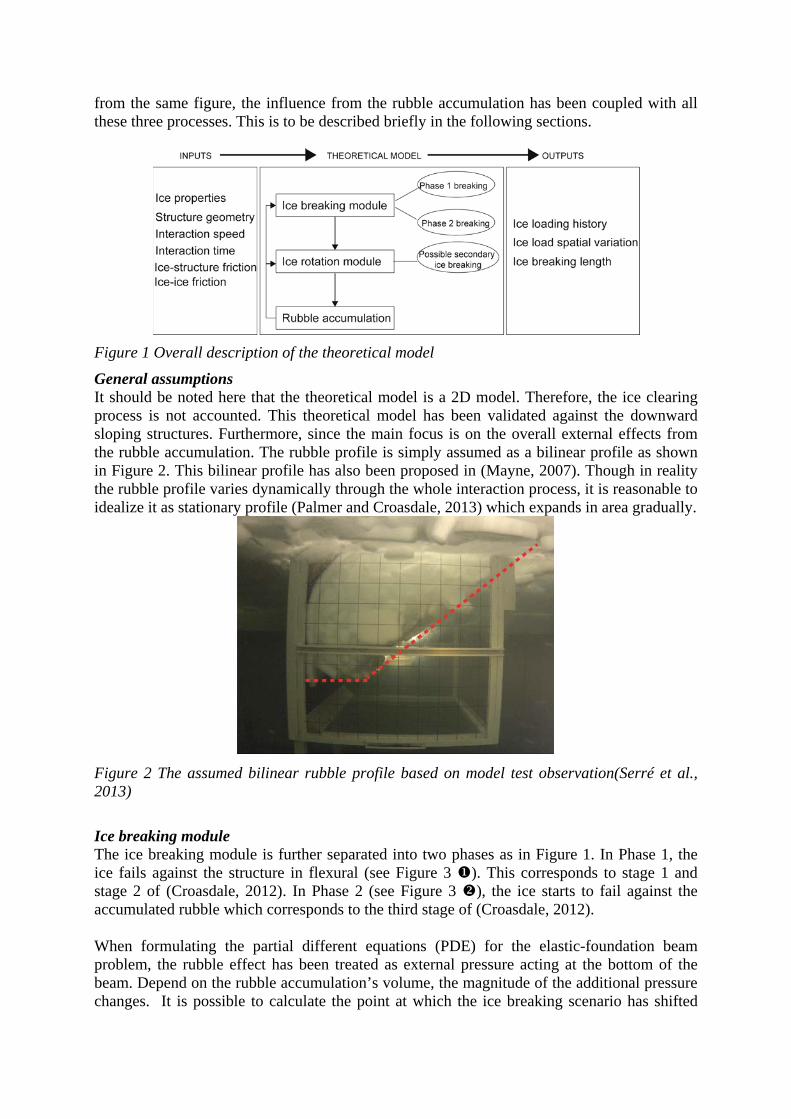
General assumptions It should be noted here that the theoretical model is a 2D model. Therefore, the ice clearing process is not accounted. This theoretical model has been validated against the downward sloping structures. Furthermore, since the main focus is on the overall external effects from the rubble accumulation. The rubble profile is simply assumed as a bilinear profile as shown in Figure 2. This bilinear profile has also been proposed in (Mayne, 2007). Though in reality the rubble profile varies dynamically through the whole interaction process, it is reasonable to idealize it as stationary profile (Palmer and Croasdale, 2013) which expands in area gradually.
Figure 2 The assumed bilinear rubble profile based on model test observation(Serré et al., 2013)
Ice breaking module The ice breaking module is further separated into two phases as in Figure 1. In Phase 1, the ice fails against the structure in flexural (see Figure 3 ). This corresponds to stage 1 and stage 2 of (Croasdale, 2012). In Phase 2 (see Figure 3 ), the ice starts to fail against the accumulated rubble which corresponds to the third stage of (Croasdale, 2012). When formulating the partial different equations (PDE) for the elastic-foundation beam problem, the rubble effect has been treated as external pressure acting at the bottom of the beam. Depend on the rubble accumulation’s volume, the magnitude of the additional pressure changes. It is possible to calculate the point at which the ice breaking scenario has shifted
from Phase 1 to Phase 2 based on the criteria if the rubble pressure alone can already fail the incoming ice in flexural. Phase 2 ice breaking shares the same formula as those developed by (Croasdale and Cammaert, 1994), since in Phase 2 ice breaking scenario, no additional rubble pressure needs to be considered as in of Figure 3. It is worth mentioning here that other load components such as rubble accumulation and ice rotating load become more dominant than the ice breaking load in this phase. This will be detailed in the later sections.
Figure 3 Two different phases of the ice breaking process
Ice rotating module The ice rotating module takes care of the ice rotating process. Comparing to other proposed ice rotating models (Aksnes, 2011; Frederking and Timco, 1985; Kotras, 1983; Valanto, 2001), this model is featured by the consideration of ventilation effect, rubble pressure, and secondary breakings which shown in Figure 4.
Figure 4 Ice rotating module with possible secondary breakings
The formulation of the ice rotating module is based on the static force and moment balance of a rigid ice block with varying rotating angle . Rubble pressure is accounted for by an additional rubble pressure as shown in Figure 5. is simply calculated as the density difference between water and ice rubble multiplied by the depth of the rubble profile. This rubble profile has been illustrated in Figure 2 and keeps increasing as the ice penetration increases. In Figure 5, there shows also a triangle shaped hydrostatic pressure with maximum value of
. However, due to the lowered water level (in blue color), this value is multiplied with a reduction coefficient . This lowered water level phenomena is the previously mentioned ventilation and backfill effect. The ventilation effect has long been recognized in the level ice and ship interaction community (Valanto, 2001). The concept of ventilation and backfill effect is illustrated in Figure 6. During the ice rotating phase, depending on the interaction speed , the water flushes back to the top of the rotating ice beam either fully (see Figure 6
(c)), partially (see Figure 6 (b)) or not at all (see Figure 6 (d)). In the work of Valanto (2001), since the interaction speed of ship and ice is relatively high, he has assumed the full ventilation phenomena as in Figure 6 (d). For most ice and sloping structure interactions, since the interaction speed is rather low, the water has a chance to backfill on top of the rotating ice beam. This is termed as the backfill process which works against the ventilation effect. In previous research regarding level ice and sloping structure interactions, it is usually assumed that the ventilation effect is not significant and therefore the no-ventilation assumption is usually made as in Figure 6 (c). However, based on the model ice tank observation and calculation made in (Lu, 2010), and also a detailed study made in (Lu et al., 2012), it is suggested to take into account the combined effect of the ventilation and backfill effect above a interaction speed of about 0.5 m/s. This allows us to calculate a reasonable ice rotating load which is neither too high for full ventilation assumption nor too low for no ventilation assumption.
Figure 5 A free body diagram of the rotating broken ice
Figure 6 Illustration of the ventilation and backfill effect (a) the initial stage of the ice rotating process; (b) water backfill at moderate interaction speed; (c) the assumption of no ventilation at low interaction speed; (d) the assumption of full ventilation at high interaction speed
In the study of the current paper, the influence from ventilation is investigated by varying the value of (i.e. a reduction coefficient of ) which has been formulated in the static force and moment balance as in Figure 5. This coefficient is varied between 0 and 1 in corresponding to the no ventilation and full ventilation assumptions respectively.
Ice accumulation module The ice accumulation module is rather intuitive. It accounts for two important load contributions to the total ice load due to the presence of rubble accumulations. The first one is the static buoyancy of rubble which applied directly onto the structure (note here that the rubble buoyancy which acts at the bottom of the incoming ice has been excluded from this and included in the ice breaking load ). The second load is the rubble pressure induced friction against the ice from being pushed towards the structure, . This load component is in analogy to the load component of Croasdale’s mdoel. Since this module is not quite relevant to the current targets of study, it is not introduced further into detail here.
A case study based on the theoretical model
In the second part of this paper, the scenario of level ice interacting with wide downward sloping structure is investigated by the previous introduced theoretical model. As a case study, typical input values were used to study the rubble accumulation effect, and the ‘ventilation and backfill’ effect. Basically, the following issues are covered within each module:
Ice breaking module a. How is the new ice breaking module comparing to the Croasdale’s model? b. Additional rubble pressure’s influence on the ice breaking load/length
Ice rotating module a. The influence of additional rubble pressure and ventilation effect b. Secondary ice breaking during the ice rotating phase
The inputs to the current theoretical model are shown in Table 1 for a 45 degree downward sloping structure.
Table 1 Inputs for the theoretical model calculation
500 flexural strength of ice in full scale [kPa]; 1 thickness of ice in full scale [m]; 5 the height of the underwater part of the sloping surface [m]; 900 Density of ice [kg/m3]; 1025 Density of water [kg/m3]; 10000 Young’s modulus of the model ice [MPa]; 0.1 Ice structure friction coefficient [], obtained by standard test in HSVA; 0.3 Ice-ice friction coefficient []; taken from (Paavilainen et al., 2011;
Sukhorukov et al., 2012) , 21 The maximum rubble height during the accumulation stage [m], this value
is decided by the structure’s geometry and ice clearing efficiency; 0.3 Rubble porosity []; 30 Repose angle of the accumulated rubble [deg]; 0.20 Interaction speed [m/s]; 200 Ice penetration length [m];
Results of the ice breaking module In the original work of Croasdale and Cammaert (1994), the authors separated five different load components as listed in Table 2.
Table 2 Horizontal ice load components of the Croasdale's model
the horizontal ice load due to the flexural failure of level ice; the horizontal load needed to push the ice through the rubble, mainly to
overcome the ice-ice friction resistance due to the excessive weight/buoyancy from the accumulated rubble;
the horizontal load needed to push the ice though the sloping surface, mainly to overcome both the ice-structure and ice-ice friction resistance due to the excessive weight/buoyancy from the accumulated rubble;
the horizontal load component of the load to support the ice rubbles which are assumed to rest on the incoming intact level ice;
the load needed to deflect the ice rubbles which were pushing along the sloping surface.
One of the major assumptions made in this model is that the ice rubbles were able to rest upon the incoming intact ice. The weight/buoyancy1 of the ice rubbles is supported by the incoming level ice and further transferred to the sloping structure leading to a horizontal load component . This load component is considered in a decoupled manner with the ice breaking load (see Figure 7 (a)). As a matter of fact, the rubbles which are resting on the incoming ice is also influencing the ice breaking load by adding additional rubble pressures on the ice sheet. Furthermore, the buoyancy/weight of the rubbles in the shaded area is not necessarily wholly transferred to the structure (see Figure 7 (b)). Therefore, in the newly developed theoretical model, the rubble pressure which leads to additional bending moment in the ice beam is accounted for in the formulation. Another assumption implicitly made in the original work is that the Croasdale’s model works only when the incoming ice is able to fail against the structure (i.e. in Phase 1 ice breaking scenario). When the ice starts to fail against the accumulated rubbles, cautions and modifications should be adopted when utilizing this model (Palmer and Croasdale, 2013). Within the framework of the current theoretical model, the above two assumptions have been addressed. Based on the inputs listed in Table 1, a case study was made as shown in Figure 8. In Figure 8, additional inputs for calculating in Croasdale’s model listed in Table 3 are taken from (Serré, 2011). The Phase 1 ice breaking scenario and Phase 2 ice breaking scenario are separated. The ice breaking length distribution in comparison to the ice penetration is also shown in Figure 9.
Table 3 Addtional inputs for the calculation of HL term of Croasdale's model
45 the friction angle of ice rubble [deg]; 735 the internal cohesion of ice rubble [Pa].
1 For upward sloping structures, the accumulated ice rubbles’ weight lead to additional ice load; while for downward sloping structures, the accumulated ice rubbles’ buoyancy lead to additional ice load to the structure.
Figure 7 Comparison of the ice breaking module with the presence of rubble accumulation (a) Croasdale's model (b) the current model which couples the rubble pressure with the ice breaking process
Figure 8 Line load calculated by the ice breaking process (in flexural)
Figure 9 Ice breaking length comparison
Discussions of the ice breaking module The assumptions of the Croasdale’s model have been introduced and compared with the currently used theoretical model in the previous section. Based on a case study, the ice breaking load comparisons are made in Figure 7. It can be seen from Figure 7 that the ice breaking process need to be separated into two different phases. For the current case, when the rubble height is above eight times of the ice thickness, the rubble pressure from beneath alone can already fail the incoming ice in flexural. This is to say, the incoming level ice starts to fail against the accumulated rubble. It should be stressed here that the current discussion is mainly focused on the ice breaking load instead of the total ice load. The ice breaking load here refers to the load needed to fail the incoming ice in flexural. In the ice breaking load comparisons, four different situations were compared. At first, the load component in Croasdale’s model refers to the load needed to fail the incoming ice in flexural. Since its algorithm is decoupled with the rubble accumulation’s weight/buoyancy , it remains a constant irrespective the amount of rubble that have accumulated beneath the level ice. In Croasdale’s model, the component stands for the load needed to support the rubbles’ weight/buoyancy which rests on the ice beam and is transferred totally onto the structure. If adding these two load components and together, the combined rubble effects and ice breaking load are shown as in Figure 8. However, if the Croasdale’s model was utilized without discriminating the above two mentioned different phases, the joint effect of the above two load would monotonically increase with the ice rubble accumulations (i.e. the curve with triangles). It is more physical that, after the ice starts to fail against the accumulated rubbles, the rubbles’ weight/buoyancy transferred to the structure is expecting a drop. To be conservative, a cut-off (i.e. the curve with squares) is made on these two loads after the interaction process has shifted into the Phase 2 ice breaking scenario. The previous discussions are made upon the assumption that the rubble accumulation has no effect on the ice breaking process based on Croasdale’s model. As a matter of fact, in Phase 1 ice breaking scenario, the rubbles were resting upon the incoming level ice (see Figure 7 (b)). This generates additional bending moment in the ice beam. Moreover, the rubbles’ weight/buoyancy is not entirely transferred to the structure. If such additional pressure is formulated in the PDEs of the elastic-beam algorithm, the ice breaking load in Phase 1 ice breaking scenario would appear as the curve with circles. The load is less conservative comparing to the decoupled calculation as in Croasdale’s model. This is understandable since the presence of rubble pressure actually helps to break the incoming ice. However, in Phase 2 ice breaking scenario, the bending of the incoming level ice is not anymore influenced by the ice rubbles since usually there is no rubble beneath the incoming ice. This is shown in Figure 3 . The bending failure in this case is calculated in the same way to calculate as in Croasdale’s model. But the sloping angle is no longer the angle of the structure. The sloping angle of the rubble profile is used in this case. Since the rubble profile angle is usually smaller than the structure’s sloping angle, the horizontal ice breaking load is thus lowered. This is shown in the curve with circles in the Phase 2 ice breaking region. In terms of the ice breaking length, as is shown in the dark dashed horizontal line in Figure 9, the croasdale’s model predicts a constant ice breaking length since the ice bending failure is not coupled with the presence of ice rubble accumulation. As for the current investigated theoretical model, in Phase 1 ice breaking scenario, the additional rubble pressure beneath the incoming ice has shifted the breaking point closer to the structure, thus leads to shorter ice
breaking length. It can be seen from the red curve in Figure 9, in Phase 1 ice breaking scenario, the amount of rubble accumulation decrease the ice breaking length. Results of the ice rotating module Within the ice rotating module, the current case study intends to identify the importance of rubble accumulation and the ventilation effects. Furthermore, secondary ice breaking after the initial bending failure is also investigated. In this numerical study, the same inputs as the previous example calculation were utilized except that in the current calculation, a ten metre long ice beam is assumed undergoing the rotation process. Based on the free body diagram as shown in Figure 5 and its force and moment balance, the interested results are calculated in a one-to-one relationship with the rotating angle . 1. The effects of additional rubble pressure and ventilation effects Three different cases are considered here as shown in Table 4. Here is the parameter denoting the effects from the combined ventilation and backfill effect (Lu et al., 2012). Setting 0 means there is no ventilation effect (i.e. low speed interaction), and 0.5 represents a partial ventilation case (Lu et al., 2013). 0 represents there is no ice rubbles accumulated beneath the rotating ice beam while 10 means that a rubble profile with a rubble height of 10 metre depth is accumulated beneath the incoming level ice.
Table 4 Three different cases to study the influence of rubble pressure and ventilation effects within the ice rotating module
Case Rubble pressure Ventilation effect Purpose 1 0 0 Base case 2 10 0 Rubble pressure influence 3 0 0.5 Ventilation factor influence Within these three different cases, the moment distribution along the rotating beam is extracted as shown in Figure 10. In the meantime, the load required to maintain such rotating process requires a perfect combination of vertical and horizontal force acting at the contact tip of the rotating beam. This is not always true. However, to keep the concept simple and focus on the current study, it is assumed here that the rotating process is always in static balance. And the rotation moment and vertical force are given priority to be in balanced state. And the horizontal rotating force
is derived from . In Figure 11, the results of in these three different cases are presented. It should be noted here that a concept of ‘border of critical rotation angle’ has been introduced here. This border represents the instance at which the contact point of the ice beam’s freeboard decreases to 0 due to the rotation. Physically, this represents the instance that the water has a chance to flood over the top of one end of the rotating beam; mathematically, this represents a sudden change in the formulations from ‘elastic foundation assumption’ to ‘elastic plastic foundation assumption (Lu et al., 2013). However, the previous two calculations are based on an assumption that the ice beam would not fail during the rotating process (i.e. without secondary ice breakings). As a matter of fact, it is necessary to monitor the stress profile during the ice rotation and extract the possible
maximum stress encountered during the rotation course. In Figure 12, rubble pressure and ventilation effect’s influence on the stress profile are presented.
Figure 10 The moment distribution during the ice beam rotating process (a:case1, b:case2, c:case3 as in Table 4)
Figure 11 The vertical ice rotating force history during the ice beam rotating process (a:case1, b:case2, c:case3 as in Table 4)
Figure 12 The maximum stress profile during rotation(a:case1, b:case2, c:case3 as in Table 4)
2. Secondary ice breaking and ice breaking length It has been observed in (Timco, 1984) that during the ice rotating process, the initially broken ice would further broken into 2 or 3 smaller pieces. Here the secondary ice breaking is defined as the breakings of a rotating ice block after its initial bending failure from an intact ice sheet. In the previous case study, the maximum stress profile and vertical rotation load history are all available. If a higher than flexural strength stress level is detected during the rotation process, then the calculation stops and a cut off is applied to Figure 11 so as to extract the rotation force and the corresponding new broken ice size. The ice breaking length is updated accordingly.
In an iterative manner, the same criteria are applied to sift through the updated ice breaking lengths to make sure the eventual ice breaking length is short enough to be rotated parallel to the sloping surface without further secondary breakings. In this section, it is aimed at showing how the secondary ice breaking would influence the eventual ice breaking lengths’ distribution. Utilizing the same inputs as in Table 1, and the procedure described in the above. Calculation is made within the ice rotation module. Two different cases were running here. One is without ventilation (i.e., 0) and another is with partial ventilation (i.e., 0.5). The initial ice breaking length and the final ice breaking length are shown in Figure 13.
Figure 13 Secondary ice breaking and the distribution of ice breaking length (a) results based on 0; (b) results based on 0.5
Discussions of the ice rotating module In terms of the moment distribution along the rotating ice beam, it can be seen from Figure 10 that the presence of rubble pressure or the presence ventilation effect tend to increase the moment of the rotating beam by almost an order of magnitude. With 0, the largest moment takes place at the very initial stage of rotation while starts to decrease in further rotation course. The location of the maximum moment concentrates at a location close to the contact point of the rotating beam. When 0, it appears that the largest moment keeps increasing with the rotation angle and the maximum moment location also keeps moving towards the direction where the structure is. When the ventilation effect is present, during the rotating course, the rotating beam tends to ‘jump’ up out of water to achieve a balanced state. This is in accordance with observation that a rotating beam tends to rise up before being totally submerged. This means that the rotation centre is moving towards the structure. This in agreement with the observation statement in (Valanto, 2001). It can be seen in Figure 11 that the presence of rubble accumulation or ventilation effect affects the rotating load greatly with the same numerical test set-up. When there are no ventilation and rubble pressure effects, the largest load encountered is at the end of the rotation within the elastic-foundation range (i.e. on the left side of the critical angle border). On the other hands, in both cases with ventilation or rubble pressure effects, the largest resistance encountered is within the plastic-foundation rotation range (i.e. on the right side of the critical border ). And the resistance eventually decreases consistently with the rotation angle. It is shown by Figure 12 that the additional rubble pressure or ventilation effects lead to larger maximum stress during ice rotation. If taken the ice flexural strength 500kPa, it can be seen from Figure 12 (a) that when there are no ventilation effect and no additional pressure a
10 metre long broken ice can be rotated freely without secondary breaking. However, in both cases of Figure 12 (b) and (c), secondary breaking is unavoidable due to the amplified tensile stress induced either by the presence of ventilation effect or rubble pressure. In terms of the influence of secondary ice breakings on the eventual ice breaking length, it can be seen from Figure 13 that the secondary ice breaking occurs once in the current case study. If there is no ventilation effect, initially, when there is limited amount of rubble accumulation, secondary ice breaking does not take place. However, as the amount of the accumulated rubble increases, secondary ice breaking starts to proceeds to grind the originally long ice breaking length into shorter ones due to the tensile stress aroused during the rotating process. However, if the ventilation effect comes into play, even in the very initial stage, the secondary breakings also take place. It can be seen from Figure 13 that the eventual ice breaking length are dominated by approximately three to six metres, comparing to the ice thickness which is 1 metre. The current theory offers another explanation to the observed shorter ice breaking length than bending theory would have predicted. Many model tests or fields observations have stated that the eventual ice breaking length is about 3-6 times of the ice thickness (Croasdale and Cammaert, 1994; Michel, 1978). And this explanation is also in line with the simulation results made in (Paavilainen et al., 2010), in which the authors calculated very short eventual ice breaking length even under the circumstance that the bending failure mode dominates.
Conclusions
This paper mainly focus on the investigation of rubble accumulation effects, ventilation effects and possible secondary ice breakings under the context of level ice interacting with wide sloping structures with the theoretical model developed in (Lu et al., 2013). Based on the previous case studies and discussions, it can be concluded that:
Rubble accumulation influences the interaction in several aspects. One of such influences also showed by the current case study is that, there are at least two phases of ice bending failure mechanisms. One is that ice fails against the structure in bending while the rubble amount is limited (i.e. Phase 1 ice breakings); another is that the incoming ice fails in bending by the rubble from beneath (i.e. Phase 2 ice breakings);
In Phase 1 ice breaking scenario, considering the presence of rubble pressure in the elastic-foundation beam formulation yields less conservative ice breaking load in comparison to the results from Croasdale’s model;
In Phase 1 ice breaking scenario, the ice breaking length decreases with the rubble accumulation amount;
Within the ice rotating phases, both the rubble induced additional pressure and the ventilation effects would increase the ice rotating load and the stress inside the rotating ice beam;
Based on the calculation and ice properties, it is found out that theoretically, secondary ice breaking takes place when the rubble accumulation is large. The secondary ice breaking process further reduces the final ice breaking length to approximately three to eight times of the ice thickness. This offered an additional explanation towards the often observed shorter ice breaking length than what elastic-foundation beam theory would predict;
Acknowledgement
The authors would like to thank the Norwegian Research Council through the project 200618/S60-PetroRisk and the SAMCoT CRI for financial support and all the SAMCoT partners. The RITAS project led by Multi-consult is greatly appreciated for the permission of using the experimental data.
Reference
Aksnes, V., 2011. A panel method for modelling level ice actions on moored ships. Part 1: Local ice force formulation. Cold Regions Science and Technology, 65(2): 128-136.
Croasdale, K. and Cammaert, A., 1994. An improved method for the calculation of ice loads on sloping structures in first-year ice. Power Technology and Engineering (formerly Hydrotechnical Construction), 28(3): 174-179.
Croasdale, K.R., 2012. Ice rubbling and ice interaction with offshore facilities. Cold Regions Science and Technology, 76–77(0): 37-43.
Frederking, R.M.W. and Timco, G.W., 1985. Quantitative analysis of ice sheet failure against an inclined plane. J. Energy Resour. Technol.;(United States), 107(3).
Kotras, T.V., 1983. Predicting ship performance in level ice. SNAME Trans, 91: 329-349. Lu, W., 2010. Ice and conical structure interactions. Student thesis Thesis, Norwegian
University of Science and Technology, Trondheim, 102-104 pp. Lu, W., Løset, S. and Lubbad, R., 2012. Ventilation and backfill effect during ice-structure
interactions, The 21st IAHR International Symposium on Ice, Dalian, China. Lu, W., Lubbad, R., Hoyland, K. and Løset, S., 2013. Physical and theoretical model to study
level ice and wide sloping structure interactions (in press). Cold Regions Science and Technology.
Määttänen, M. and Hoikkanen, J., 1990. The effect of ice pile-up on the ice force of a conical structure, Proceedings of IAHR Symposium on Ice, Helsinki.
Mayne, D.C., 2007. Level ice and rubble actions on offshore conical and sloping structures, 68.
Michel, B., 1978. Ice mechanics. Paavilainen, J., Tuhkuri, J. and Polojärvi, A., 2011. 2D numerical simulations of ice rubble
formation process against an inclined structure. Cold Regions Science and Technology, 68(1–2): 20-34.
Paavilainen, J., Tuhkuri, J.T. and Polojarvi, A., 2010. Rubble pile formation against an inclined structure-analysis of simulation results, International symposium on Ice. IAHR, Lahti, Finland.
Palmer, A. and Croasdale, K., 2013. Arctic Offshore Engineering. World Scientific. Ralston, T., 1980. Plastic limit analysis of sheet ice loads on conical structures. Physics and
Mechanics of Ice, Springer-Verlag, New York, USA: 289-308. Serré, N., 2011. Mechanical properties of model ice ridge keels. Cold Regions Science and
Technology, 67(3): 89-106. Serré, N., Lu, W., Høyland, K.V., Bonnemaire, B., Borge, J. and Evers, K.-U., 2013. Rubble
Ice Transport on Arctic Offshore Structures (RITAS), part II: 2D model scale study of the level ice action, Proceedings of the 22nd International Conference on Port and Ocean Engineering under Arctic Conditions, Espoo, Finland.
Sukhorukov, S., Maattanen, M. and Løset, S., 2012. Field Experiments on the Friction Coefficient of Sea Ice on Sea Ice. In: L.a. Lu (Editor), 21st IAHR International Symposium on Ice. Dalian University of Technology, Dalian, China.
Timco, G., 1984. Model tests of ice forces on a wide inclined structure, IAHR Ice symposium, Hamburg.
Valanto, P., 2001. The resistance of ships in level ice. SNAME, 109: 53-83.