- NASA Technical Paper 132 5 NASA TP 1325 C.1 LOAN COPY: RETURF AWL TECHNICAL LIE ‘!ClRTLANO AFB. N. A Theoretical Investigation of Noise Reduction Through the Cylindrical Fuselage of a Twin-Engine, Propeller-Driven Aircraft , I Rama B. Bhat and John S. Mixson DECEMBER 1978 https://ntrs.nasa.gov/search.jsp?R=19790005650 2020-04-15T20:27:31+00:00Z
Transcript
-
NASA Technical Paper 132 5
NASA TP 1325 C . 1
LOAN COPY: RETURF A W L TECHNICAL LIE
‘!ClRTLANO AFB. N.
A Theoretical Investigation of Noise Reduction Through the Cylindrical Fuselage of a Twin-Engine, Propeller-Driven Aircraft
A Theoretical Investigation of Noise Reduction Through the Cylindrical Fuselage of a Twin-Engine, Propeller-Driven Aircraft
Rama B. Bhat and John S . Mixson Langley Research Center Hampton, Virginia
National Aeronautics and Space Administration
Scientific and Technical Information Office
1978
SUMMARY
I n t e r i o r no ise i n the fuse lage of a twin-engine, p rope l le r -dr iven a i r c r a f t with two p r o p e l l e r s r o t a t i n g i n oppos i te d i r e c t i o n s i s s tud ied a n a l y t i c a l l y . The fuse lage i s modeled a s a s t i f f e n e d c y l i n d r i c a l s h e l l with simply supported ends, and the e f f e c t of s t r i n g e r s and frames i s averaged over t he s h e l l su r f ace . An approximate mathematical model of t he p r o p e l l e r no ise e x c i t a t i o n i s formu- l a t e d which inc ludes some of t he p r o p e l l e r no ise c h a r a c t e r i s t i c s such a s sweep- ing pressure waves around t h e s idewal l s due t o p r o p e l l e r r o t a t i o n and the loca l - i zed na ture of t he e x c i t a t i o n with the h ighes t l e v e l s near t he p r o p e l l e r plane. Resul t s are presented i n t h e form of noise reduct ion , which i s the d i f f e r e n c e between the l e v e l s of e x t e r n a l and i n t e r i o r no ise . The inf luence of p r o p e l l e r no ise c h a r a c t e r i s t i c s on the noise reduct ion is s tudied . The r e s u l t s i n d i c a t e t h a t t h e sweep v e l o c i t y of t he e x c i t a t i o n around the fuse lage s idewal l s i s c r i t i c a l t o noise reduct ion .
INTRODUCTION
One of t he main sources of i n t e r i o r no ise i n propel le r -dr iven a i r c r a f t i s the p rope l l e r no i se e x c i t a t i o n . A main pa th by which noise i s t r ansmi t t ed t o the i n t e r i o r i s through the fuse lage s t r u c t u r e . The p resen t paper i s devoted t o the study of t he noise reduct ion provided by t h e fuse lage s t r u c t u r e when sub- j ec t ed t o p r o p e l l e r noise e x c i t a t i o n and the in f luence of p r o p e l l e r no ise char- a c t e r i s t i c s on the noise reduct ion .
Some information i s a v a i l a b l e on the na tu re of t he p r o p e l l e r no ise and i t s near f i e l d behavior ( r e f s . 1 t o 7 ) which r e v e a l s a few c h a r a c t e r i s t i c s of pro- p e l l e r no ise such a s (1) the p re s su re f i e l d r o t a t i n g with the b lades causing a sweeping ac t ion around the s idewal l s of t he fuse l age , ( 2 ) t he l o c a l i z e d na ture of t he noise f i e l d on the fuse lage su r face with h ighes t l e v e l s near t he pro- p e l l e r plane, and ( 3 ) t he noise spectrum dominated by p r o p e l l e r harmonics. Ref- e rences 8, 9 , and 10 analyze i n t e r i o r no ise i n fu se l ages using s t a t i s t i c a l energy ana lys i s and d e t e r m i n i s t i c ana lyses f o r e x t e r i o r no ise p re s su re i n p u t s such a s tu rbu len t boundary l a y e r s , j e t no i se , o r p l a i n acous t i c waves. I n t e r i o r no ise i n p ropel le r -dr iven l i g h t a i r c r a f t with f l a t fuse lage s idewa l l s has been s tudied experimental ly ( r e f . l l), and a n a l y t i c a l l y cons ider ing uniform p res su re t o r ep resen t p r o p e l l e r no i se inpu t on the s idewa l l s ( r e f . 1 2 ) .
The p resen t i n v e s t i g a t i o n extends previous ana lyses by employing a more r e a l i s t i c r ep resen ta t ion of p r o p e l l e r e x c i t a t i o n p res su res and complements t he s t u d i e s d iscussed i n re ference 1 2 with regard t o fuse lage geometry by consider- i n g c y l i n d r i c a l fuse lages . An approximate mathematical model has been developed, using information a v a i l a b l e i n the r e fe rences , f o r t he p r o p e l l e r no ise exc i t a - t i o n which inc ludes some of t he p r o p e l l e r no ise c h a r a c t e r i s t i c s . Twin-engine a i r c r a f t with p r o p e l l e r s r o t a t i n g i n oppos i te d i r e c t i o n s a r e considered. The noise f i e l d s from the p r o p e l l e r s on e i t h e r s i d e of t h e fuse lage are assumed t o be symmetrical about t he c e n t r a l v e r t i c a l plane of t h e fuse lage . The o b j e c t i v e
of t h e p r e s e n t i n v e s t i g a t i o n is t o s tudy t h e q u a n t i t a t i v e inf luence of t h e pro- peller noise c h a r a c t e r i s t i c s on t h e no i se r educ t ion through the fuselage s ide - w a l l s . Two s i z e s o f fuse l age s t r u c t u r e are s t u d i e d , one r ep resen ta t ive o f a l a r g e passenger a i rcraf t fuse l age and t h e o t h e r corresponding t o t h a t of a l i g h t a i r c r a f t fuselage.
The o v e r a l l development of t h e a n a l y s i s i n t h i s s tudy c l o s e l y fol lows t h a t i n reference 10. The fuse l age i s modeled as a c y l i n d r i c a l s h e l l s t i f f e n e d by s t r i n g e r s and r i n g frames and having simply supported ends. The e f f e c t s o f s t i f f e n e r s are averaged over t h e fuselage surface. The a n a l y s i s for t h e i n t e r i o r no i se i n t h e fuse l age is c a r r i e d o u t using the approximate model of p r o p e l l e r noise i n p u t on t h e fuselage s t r u c t u r e and the normal mode approach t o determine the response of t he fuse l age and the r e s u l t i n g p r e s s u r e f l u c t u a t i o n s i n t h e i n t e r i o r a c o u s t i c f i e l d . The frequency range considered i s from 0 t o 500 Hz and includes t h e blade passage frequency and t h e f i r s t few harmonics, which are t h e dominant sources of p r o p e l l e r noise . The no i se r educ t ion through the fuselage s idewa l l s i s t h e d i f f e r e n c e between t h e e x c i t a t i o n no i se level on t h e fuse l age surface and t h e space-averaged i n t e r i o r no i se l e v e l w i th in t h e fuselage. Resu l t s showing t h e in f luence of p r o p e l l e r noise c h a r a c t e r i s t i c s on noise reduct ion are presented.
SYMBOLS
The u n i t s used f o r phys i ca l q u a n t i t i e s de f ined i n t h i s paper are given i n t h e I n t e r n a t i o n a l System ( S I ) of u n i t s .
A r 1%
a l r a 2 r b p b 2
2 c ross - sec t iona l areas of r i n g frame and s t r i n g e r , r e spec t ive ly , m
d i s t a n c e s d e f i n i n g t h e fuselage su r face area subjected t o pro- pe l le r no i se e x c i t a t i o n , shown i n f i g u r e 1, m
c1,c2,c3,c4
'mi
C speed of sound i n a i r , m/sec
cons t an t s appearing i n equation ( B 2 )
modal cons t an t def ined i n equation (B11)
E modulus o f e l a s t i c i t y of fuselage material, Pa
moduli of e l a s t i c i t y of r i n g frame and s t r i n g e r materials, % P E S
r e s p e c t i v e l y , Pa
Fmni general ized force f o r (mi) mode
f frequency , Hz
reference frequency, Hz
shear moduli of r i n g frame and s t r i n g e r materials, r e spec t ive ly , Pa
f r
G r Gs
H frequency response def ined i n equation (6)
2
h thickness of fuse l age material, m
'mi
I n
Ir, Is
Jn
Jr, Js
k
L
P
P
Pe
Qac
Qmni
qmni
R
r
r A
s
t
i n t e g r a l s def ined i n equat ions (ll), ( 1 2 ) , and (13)
modified B e s s e l f unc t ion of f i r s t kind and of n th o rde r
moments of i n e r t i a f o r r i n g frame and s t r i n g e r , r e spec t ive ly
B e s s e l f unc t ion of f i r s t kind and n t h o r d e r
t o r s i o n a l cons t an t s for r i n g frame and s t r i n g e r , r e spec t ive ly
wave number w/c de f ined i n equat ion (B3)
l eng th of fuse l age , m
d i f f e r e n t i a l o p e r a t o r s i n equat ion ( A I ) , r ,s = 1, 2 , 3
r i n g frame and s t r i n g e r spacings, r e s p e c t i v e l y , m
general ized m a s s o f (mi) mode
moment r e s u l t a n t i n x -d i r ec t ion
number o f h a l f waves along cy l inde r a x i s
stress r e s u l t a n t i n x -d i r ec t ion
number of f u l l waves around cy l inde r circumference
p res su re amplitude of e x c i t a t i o n p res su re , Pa
i n t e r i o r no i se p r e s s u r e , Pa
e x c i t a t i o n p r e s s u r e , Pa
dynamic magnif icat ion f a c t o r f o r a c o u s t i c modes
dynamic magnif icat ion f a c t o r f o r (mni) s t r u c t u r a l mode
gene ra l i zed coordinate of (mni) s t r u c t u r a l mode
r a d i u s of fuse l age , m
r a d i a l coordinate of fuse l age , m
dimensionless r a d i a l coordinate r / R
number of radial a c o u s t i c waves
t i m e , sec
3
Umni
U
u1''2
V
vmni
V
vlf v2
wmni
W
wa
X
Y
Z
zr,zs
c1
Ymni
e' 1-I
P
mode f u n c t i o n s for fuse l age displacements i n x-direct ion
fuselage displacement i n x -d i r ec t ion , m
fu se l age displacement amplitudes i n x-direct ion, m
sweep v e l o c i t y of e x c i t i n g p r e s s u r e waves, m / s e c
mode func t ions f o r fuselage displacements i n y-direct ion
fuse l age displacement i n y-direct ion, m
fuse l age displacement amplitudes i n y-direct ion, m
mode func t ions f o r fuselage displacements i n z-direct ion
rad ia l displacement of fuselage, m
r a d i a l displacement of a i r p a r t i c l e i n fuselage i n t e r i o r , m
coordinate i n long i tud ina l d i r e c t i o n of fuselage, m
coordinate i n c i r cumfe ren t i a l d i r e c t i o n of fuselage, m
coordinate i n r ad ia l d i r e c t i o n of fuse l age , m
e c c e n t r i c i t i e s of r i n g f r a m e and s t r i n g e r cen t ro ids from fuse l age skin middle p l ane , m
parameter de f ined i n equation (B3)
q u a n t i t y de f ined i n equat ion (B17)
phase angle o f frequency response of fuselage displacement, rad
Poisson 's r a t i o f o r material of fu se l age
dens i ty o f fuselage sk in mater ia l , kg/m3
average d e n s i t y of s k i n - s t r i n g e r fuse l age s t r u c t u r e , kg/m3
d e n s i t y o f a i r , kg/m 3
d e n s i t i e s of r i n g frame and s t r i n g e r m a t e r i a l s , r e spec t ive ly , kg/m3
mode func t ions of (mi) a c o u s t i c modes
coordinate i n c i r cumfe ren t i a l d i r e c t i o n f o r i n t e r i o r acous t i c space Y/R
q u a n t i t y de f ined i n equat ions (B4)
4
w frequency, rad/sec
s t r u c t u r a l modal f requencies , rad/sec
a c o u s t i c modal f requencies , rad/sec
wm
WINIS
Subsc r ip t s :
i , j , m , n , r , s , ~ , S i n t e g e r s
Dots over symbols denote t i m e de r iva t ives .
Primes over symbols denote d e r i v a t i v e s with r e s p e c t t o s p a t i a l coordinates .
B a r s over symbols denote amplitudes.
ANALY S IS
Since p r o p e l l e r no i se i s predominant near t h e blade passage frequency and the f i r s t few harmonics, which l i e i n the low-frequency range, a fuselage model t h a t i s simple b u t s u i t a b l e i n the low-frequency range i s requi red . Such:a model i s a v a i l a b l e i n r e fe rence 13 i n which the e f f e c t of s t r i n g e r s and r i n g frames a r e averaged over t h e fuse lage sur face . Shown i n f i g u r e l ( a ) i s a fuse lage s t r u c t u r e i d e a l i z e d a s a simple c y l i n d r i c a l s h e l l with r e in fo rc ing s t r i n g e r s and r i n g frames. The fuse lage i s exc i t ed by p r o p e l l e r no ise exc i t a - t i o n , and t he r e s u l t i n g v i b r a t i o n s of t he fuse lage s t r u c t u r e e x c i t e t he i n t e r i o r a i r space causing i n t e r i o r no ise . The displacement response of the fuse lage w a l l s i s c a l c u l a t e d using a normal mode approach. The i n t e r i o r noise i n the fuse lage i s obta ined by equat ing the displacement of t he fuse lage w a l l t o t h a t of t he a i r p a r t i c l e near t h e w a l l . This p lan of development follows r e fe r - ence 10 c l o s e l y .
The fol lowing d i scuss ion g ives the main f e a t u r e s of t he ana lys i s . De ta i l s of t he d e r i v a t i o n of t h e forced-response equat ions f o r t h e fuse lage s t r u c t u r e are given i n appendix A, and d e t a i l s of the i n t e r i o r no ise d e r i v a t i o n s a re given i n appendix B.
Displacement Response of Fuselage S t r u c t u r e
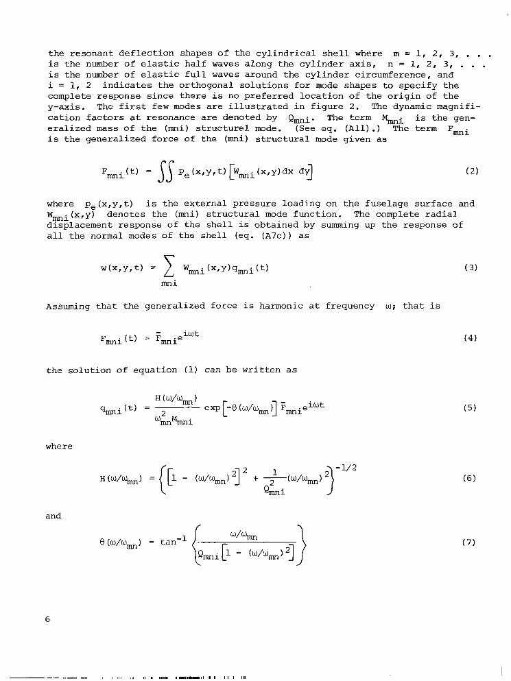
The equat ion of motion f o r t he (mi) mode of t h e fuse lage s t r u c t u r e is (see eq. (A13))
r ep resen t s t h e where q m i r e p r e s e n t s t h e genera l ized coord ina tes and n a t u r a l f requencies of t h e fuse lage s t r u c t u r e . The s u b s c r i p t s (mi) spec i fy "F
5
t he resonant d e f l e c t i o n shapes of t he c y l i n d r i c a l s h e l l where m = 1, 2 , 3 , . . . i s t h e number o f e l a s t i c ha l f waves along t h e c y l i n d e r a x i s , n = 1, 2 , 3, . . . i s the number of e l a s t i c f u l l waves around the c y l i n d e r circumference, and i = 1, 2 i n d i c a t e s t h e or thogonal s o l u t i o n s f o r mode shapes t o s p e c i f y t h e complete response s ince t h e r e i s no p r e f e r r e d l o c a t i o n of t h e o r i g i n of t h e y-axis. The f i r s t few modes a r e i l l u s t r a t e d i n f i g u r e 2 . The dynamic magnifi- c a t i o n f a c t o r s a t resonance are denoted by Q,i. The term Gi i s the gen- e r a l i z e d m a s s of t h e (mi) s t r u c t u r e 1 mode. (See eq. ( A l l ) .) The term Fmi i s t h e genera l ized fo rce of the (mi) s t r u c t u r a l mode given as
where p e ( x , y , t ) WFi(x,y) denotes the (mi) s t r u c t u r a l mode func t ion . The complete r a d i a l displacement response of t h e s h e l l is obta ined by summing up the response of a l l t he normal modes of t he s h e l l (eq. (A7c)) as
i s the e x t e r n a l pressure loading on t h e fuse lage su r face and
m n i
Assuming t h a t t he genera l ized force i s harmonic a t frequency w; t h a t i s
i w t - F m i (t) = Fmnie
the so lu t ion of equat ion (1) can be w r i t t e n a s
where
and
(4)
6
..-.. ,.._ , , ... ,. I. . ,111. 11...11.1..11 I1 I I 1 I 111
Subsequently, t he r a d i a l displacement of t he s h e l l i s obta ined by combining equat ion ( 5 ) and equat ion ( 3 ) as
P r o p e l l e r Noise Exc i t a t ion
Previous s t u d i e s on t h e na tu re of t h e p r o p e l l e r no ise ( r e f s . 1 t o 7) i nd i - c a t e t h a t :
1. The noise f i e l d generated by t h e p r o p e l l e r b l ades r o t a t e s wi th t h e p r o p e l l e r .
2. The p r o p e l l e r no i se e x c i t i n g the fuse lage su r face has the h ighes t l e v e l s near t he p r o p e l l e r plane.
3 . The spectrum of t h e p r o p e l l e r no i se i s dominated by p r o p e l l e r harmonics.
By employing these c h a r a c t e r i s t i c s of p r o p e l l e r no ise e x c i t a t i o n an approximate mathematical model i s formulated.
In f i g u r e l ( b ) t h e l o c a t i o n of t he p r o p e l l e r s i s shown r e l a t i v e t o t h e fuse lage . The p r o p e l l e r n o i s e on t h e fuse lage i s i l l u s t r a t e d by the hatched a r e a around t h e fuse lage . I t i s assumed t h a t t he p r o p e l l e r s on e i t h e r s i d e of t h e fuse lage a r e r o t a t i n g i n oppos i te d i r e c t i o n s and a l s o t h a t t h e i r no i se f i e l d s inc iden t on t h e fuse lage s idewa l l s a r e symmetrical with r e spec t t o the fuse lage v e r t i c a l p lane of symmetry. I t i s a l s o assumed t h a t t he noise f i e l d i s t r a v e l i n g around t h e fuse l age with cons t an t v e l o c i t y V, as shown i n f i g - ure l ( b ) , by t h e a r c around the fuse lage . This approximate r ep resen ta t ion of t h e p r o p e l l e r no ise f i e l d i s mathematically expressed, f o r a p a r t i c u l a r pro- p e l l e r harmonic, a s
p e ( x , y , t ) = P exp 1 i w ( t - ibl]
p e ( x , y , t ) = p exp 1 i w ( t + :".,i P,(X,Y,t) = 0 (e 1 sewhe r e ) J
7
where w i s t h e frequency of t h e harmonic, P i s t h e amplitude of t he e x c i t i n g p res su re , V i s t h e v e l o c i t y of t h e p r e s s u r e waves t r a v e l i n g around t h e fuse- l age due to the p r o p e l l e r r o t a t i o n , and face a r e a subjec ted t o p r o p e l l e r n o i s e e x c i t a t i o n . (See f i g s . l ( a ) and l ( b ) .) The sweep v e l o c i t y V and t h e frequency w can be r e l a t e d t o the p r o p e l l e r parameters. In equat ions (9), V = m corresponds t o the case of uniform pres- sure loading on t h e fuse lage sur face .
al,a2!bl,b2 spec i fy the fuse lage sur-
Combining equat ions (9) and equat ion (2 ) and making use of equat ions ( A 8 ) and (A9), t h e genera l ized fo rce f o r t he (mni) mode i s obtained as
The i n t e g r a l s Imi i n equat ion (10) a r e eva lua ted t o ob ta in
Iml = 0
due t o the symmetry of t h e fo rc ing p res su re f i e l d about t he v e r t i c a l p lane of symmetry of t h e fuse lage , and
v ( b 2 - bl) s i n - - - s i n - --- ~. R + 1 R
[““2 w nb1 - s i n - R
n u R V - - -
f
- cos - .
R . . + cos - nbl - cos - t ( b 2 - R
n u R V - - -
8
when n/R # w/V and
1 L = -Eo. (mnal/L) - cos (mlia2/L) Im2 mn
+ ~
w nb1 v ( b 2 - bl)] - s i n - + (b2 - b l ) COS
R n (11 - + - R V
.) V
+ (b2 - bl) s i n - mbl) (13)
+ --(b2 - bl)] - COS - nb1 R
n w V - + - R V
+ i
when n/R = w/V. I n equat ion (13) when n/R = w/V, t h e sweep v e l o c i t y V matches with t h e bending wave v e l o c i t y around the fuselage wR/n and hence corresponds t o t h e case of coincidence. S u b s t i t u t i o n of the general ized fo rce given i n equation (10) i n t o equat ion (8) y i e l d s the displacement response of t h e fuselage s t r u c t u r e .
I n t e r i o r Noise Analysis
The i n t e r n a l a c o u s t i c f i e l d , which i s exc i t ed by t h e fuse l age v i b r a t i o n s , is de f ined by t h e wave equation
v p = - - 2 1 azp .2 a t 2
and t h e boundary cond i t ions chosen f o r t he ends and w a l l of t h e c y l i n d r i c a l s ec t ion . To p e r m i t s i m p l i f i e d a n a l y s i s , open-end cond i t ions are assumed; t h a t i s , t h e a c o u s t i c impedance, which i s def ined as the r a t i o o f a c o u s t i c p re s su re t o par t ic le v e l o c i t y , i s taken as zero. While it i s recognized t h a t i n an a c t u a l fu se l age t h e ends have f i n i t e impedance, t h e use of t he open-end condi- t i o n s should have l i t t l e e f f e c t on t h e c a l c u l a t e d modal d e n s i t y of t h e sound f i e l d i n t h e frequency range considered.
An expression f o r t h e i n t e r i o r no i se p re s su re i s obtained by assuming the boundary cond i t ions a t t h e w a l l t o be such t h a t t h e a c o u s t i c and t h e s t r u c t u r a l
9
analyses are coupled. The r a d i a l d e f l e c t i o n s of the s h e l l a r e equated t o the r a d i a l displacements of t he a i r p a r t i c l e s ad jacen t t o the s h e l l w a l l s i n t h e i n t e r i o r space. (See appendix B f o r d e t a i l e d a n a l y s i s . ) The expressions f o r the space-averaged mean-square i n t e r i o r no i se i s given by (see eqs. (B16), (B18), and (B25))
I n equat ion (15 ) , JA (a) + 0 i s the condi t ion of a c o u s t i c resonance. The acous t i c resonance f requencies a r e given by wmns ( s ee eq. ( B 1 4 ) ) where m = 1, 2, 3 , . . . i s t h e number of l ong i tud ina l h a l f waves, n = 1, 2 , 3, . . . i s the number of c i r cumfe ren t i a l f u l l waves, and s = 1, 2, 3 , . . . i s the number of r a d i a l waves. Nodal p a t t e r n s f o r a few a c o u s t i c modes a r e shown i n f i g u r e 3. A t resonance the i n t e r i o r no ise i s given by
RESULTS
Resul t s are presented f o r two fuse lage s t r u c t u r e s whose dimensions are shown i n t a b l e I. Fuselage 1 i s r e p r e s e n t a t i v e of a l a r g e pas senge r -a i r c ra f t fuse lage and fuse lage 2 corresponds t o a l i g h t - a i r c r a f t fuselage. e r t i e s of t he fuse lage ma te r i a l and a i r i n t h e fuse lage i n t e r i o r a r e given i n t a b l e 11. The magnif icat ion f a c t o r f o r s t r u c t u r a l modes QFi is chosen as 50, which corresponds t o 1 percent of t h e c r i t i c a l damping. This is t h e nominal value of damping f o r many a c t u a l s t r u c t u r e s . The magni f ica t ion f a c t o r f o r acous t i c modes Qac c r i t i c a l damping. Reference 14 suggests t h i s va lue o f t he magnif icat ion f a c t o r f o r a c o u s t i c a l l y t r e a t e d enclosed spaces i n t h e low-frequency range.
The prop-
i s chosen as 25, which corresponds t o 2 pe rcen t of t he
In order t o provide a p a r t i a l check of t h e s t r u c t u r a l p a r t of t he p r e s e n t ana lys i s , n a t u r a l f requencies of a simply supported, e x t e r n a l l y s t i f f e n e d s h e l l w e r e ca l cu la t ed and compared with experimental r e s u l t s f r o m re ference 15. The experimental model had long i tud ina l s t i f f e n e r s i n t e g r a l l y b u i l t i n t o the s h e l l . A s shown i n f i g u r e 4 , t h e agreement between a n a l y t i c a l and experimental f r e - quencies f o r t h i s check case i s good.
10
Natural Frequencies o f S t r u c t u r e and Acoustic F i e l d
I m n S
2 2 0
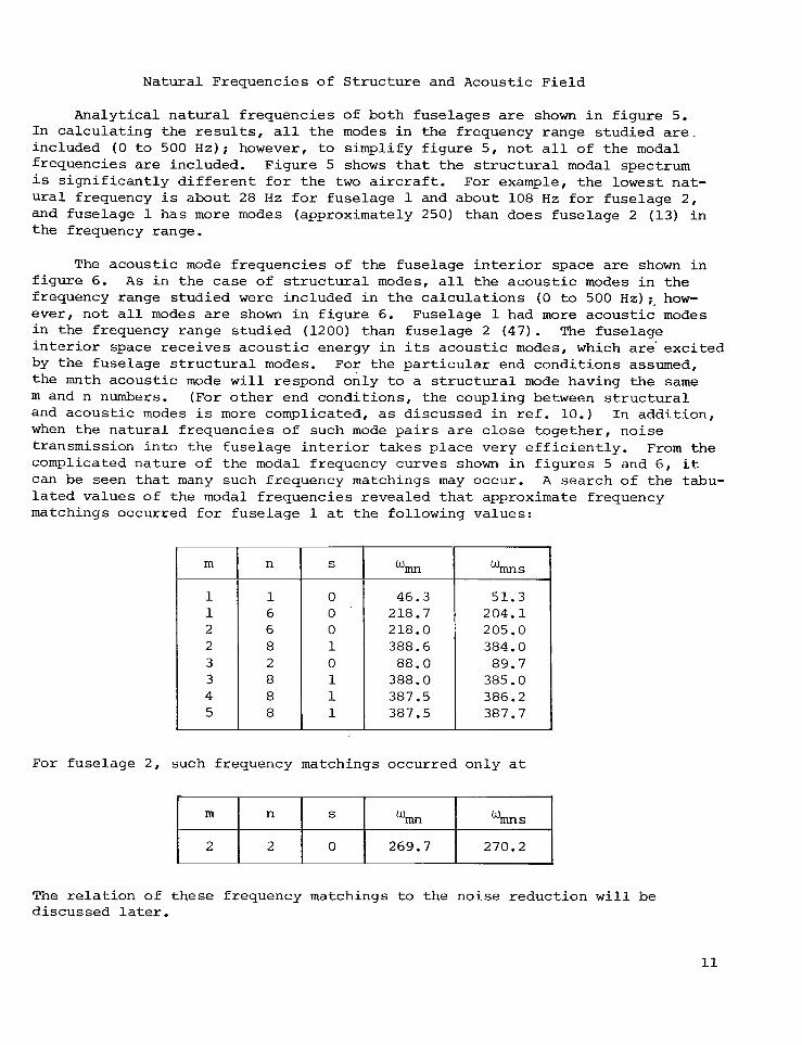
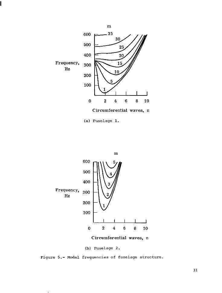
Analyt ical n a t u r a l f r equenc ie s of both fuse l ages are shown i n f i g u r e 5. In c a l c u l a t i n g t h e r e s u l t s , a l l t h e modes i n t h e frequency range s tud ied a r e . included (0 t o 500 Hz); however, t o s impl i fy f i g u r e 5, n o t a l l of t h e modal f requencies are included. Figure 5 shows t h a t t h e s t r u c t u r a l modal spectrum i s s i g n i f i c a n t l y d i f f e r e n t for t h e t w o a i rc raf t . For example, t h e l o w e s t nat- u r a l frequency i s about 28 H z f o r fuselage 1 and about 108 H z f o r fuselage 2 , and fuselage 1 has more modes (approximately 250) than does fuselage 2 (13) i n t h e frequency range.
wmn s
269.7 270.2
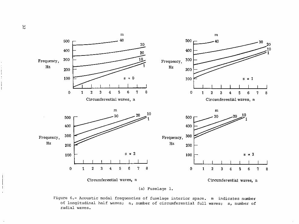
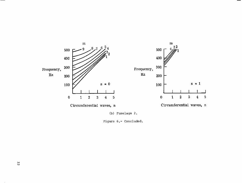
The a c o u s t i c mode f r equenc ie s of t he fuselage i n t e r i o r space are shown i n f i g u r e 6. A s i n t h e case of s t r u c t u r a l modes, a l l t h e a c o u s t i c modes i n t h e frequency range s tud ied w e r e included i n t h e c a l c u l a t i o n s (0 t o 500 H z ) ; . how- ever, n o t a l l modes are shown i n f i g u r e 6. Fuselage l had more a c o u s t i c modes i n the frequency range s tud ied (1200) than fuselage 2 (47 ) . The fuselage i n t e r i o r space r e c e i v e s a c o u s t i c energy i n i t s a c o u s t i c modes, which a r e ' e x c i t e d by the fuselage s t r u c t u r a l modes. For the p a r t i c u l a r end cond i t ions assumed, the mnth acous t i c mode w i l l respond only t o a s t r u c t u r a l mode having t h e s a m e m and n numbers. (For o t h e r end cond i t ions , t he coupling between s t r u c t u r a l and a c o u s t i c modes i s more complicated, as discussed i n r e f . 10.) In a d d i t i o n , when t h e n a t u r a l f r equenc ie s of such mode p a i r s are c l o s e toge the r , no i se transmission i n t o t h e fuse l age i n t e r i o r t akes p l a c e very e f f i c i e n t l y . From t h e complicated na tu re of t h e modal frequency curves shown i n f i g u r e s 5 and 6 , it can be seen t h a t many such frequency matchings may occur. A search of t h e tabu- l a t e d va lues of t h e modal f r equenc ie s revealed t h a t approximate frequency matchings occurred f o r fuse l age 1 a t t h e following values:
m n S
46.3 218.7 218.0 388.6 88.0
388.0 387.5 387.5
204.1 205.0 384.0
385.0 386.2 387.7
For fuselage 2 , such frequency matchings occurred only a t
The r e l a t i o n o f t h e s e frequency matchings t o t h e no i se r educ t ion w i l l be discussed la ter .
11
Noise Reduction
Numerical r e s u l t s f o r t h e i n t e r i o r no i se are c a l c u l a t e d from equat ions (15) and (16) and are p resen ted i n t h e form of no i se reduct ion, which i s def ined as
N o i s e r educ t ion = 1 0 loglo (212) (17)
- - 2 where pe i s t h e mean-square e x c i t a t i o n p r e s s u r e and p2 i s t h e space-averaged
mean-square i n t e r i o r n o i s e p re s su re . The frequency range considered i n t h e p r e s e n t s tudy i s from 0 t o 500 Hz, s ince t h i s range covers t h e blade passage frequency and t h e f i r s t few harmonics which are t h e predominant f requencies e x c i t i n g t h e s t r u c t u r e . In t h e r e s u l t s shown i n f i g u r e s 7 t o 1 2 , no i se reduc- t i o n i s s t u d i e d as a continuous funct ion of e x c i t a t i o n frequency, f o r a number of s w e e p v e l o c i t i e s . I t i s noted t h a t an i n t e r i o r no i se spectrum a c t u a l l y con- sists of tones a t t h e blade passage frequency and i t s harmonics. The no i se reduct ion a t those corresponding frequencies can be obtained from t h e continu- ous no i se reduct ion p l o t . Sweep v e l o c i t y i s a funct ion o f t h e p r o p e l l e r ro t a - t i o n a l speed and t h e d i s t a n c e from t h e p r o p e l l e r c e n t e r t o t h e fuselage s ide- w a l l . Hence, when t h e p r o p e l l e r r o t a t i o n o r t h e p r o p e l l e r c e n t e r r e l a t i v e t o t h e fuselage s idewa l l s are a l t e r e d , t he sweep v e l o c i t y i s a f f e c t e d and a d i f f e r - e n t no i se reduct ion p l o t must be computed.
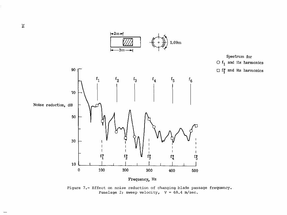
TO i l l u s t r a t e t h e e f f e c t o f blade passage frequency on noise reduct ion, a p l o t of no i se r educ t ion a g a i n s t frequency i s shown i n f i g u r e 7. The blade passage frequency i s denoted as f l Hz. The no i se r educ t ions a t f l and i t s higher harmonics are marked with c i r c u l a r symbols. I f t h e blade passage f r e - quency i s changed t o f; ( e i t h e r by changing t h e number of blades i n t h e pro- p e l l e r o r t h e speed of r o t a t i o n of t h e p r o p e l l e r ) b u t t h e sweep v e l o c i t y V i s kept cons t an t , t h e r e s u l t i n g d i s c r e t e frequency spectrum o f no i se reduct ion a s soc ia t ed wi th f; sjymbols i n f i g u r e 7. Sweep v e l o c i t y can be held cons t an t by a d j u s t i n g the d i s t ance between t h e p r o p e l l e r c e n t e r and t h e fuse l age s idewalls . I t i s seen from f i g u r e 7 t h a t , by changing the blade passage frequency, the noise reduc- t i o n changes s i g n i f i c a n t l y , depending on whether it and i t s harmonics l i e near resonances o r away from resonances. Hence, no i se reduct ion is very s e n s i t i v e t o blade passage frequency and s t r u c t u r a l and a c o u s t i c resonances.
and i t s harmonics changes as i n d i c a t e d by t h e square
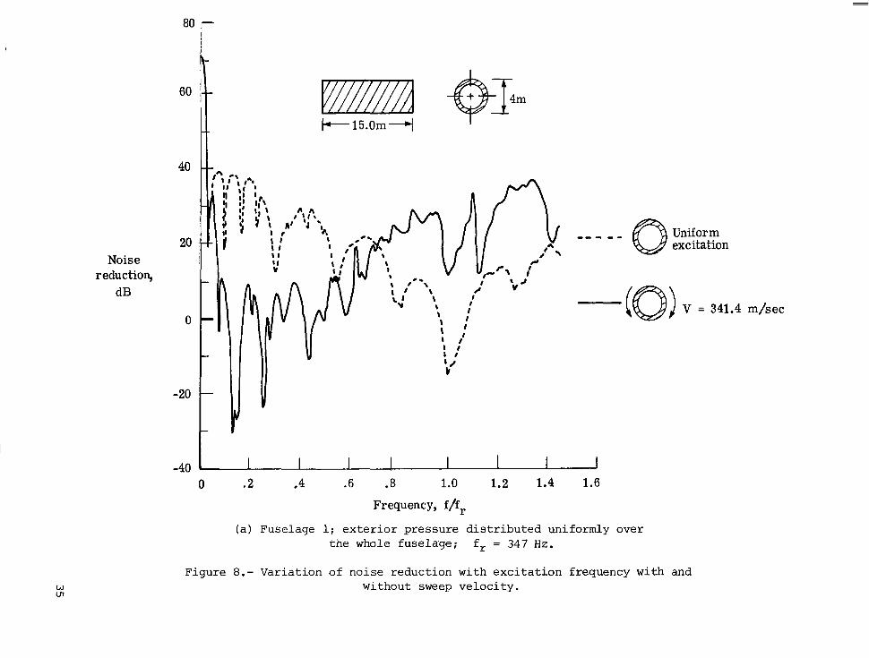
The e f f e c t of s w e e p v e l o c i t y on the no i se reduct ion i s shown i n f i g - u r e s 8 ( a ) and 8 ( b ) f o r fuse l age 1 and fuselage 2 , r e spec t ive ly . The e n t i r e su r face area of t h e fuse l ages i s exposed t o n o i s e e x c i t a t i o n as shown i n f i g - ure 8. Noise reduct ion i s p l o t t e d a g a i n s t nondimensional frequency, with t h e reference frequency f r as the nondimensionalizing frequency. The reference frequency i s t h e frequency of m = 1, n = 0 , s h e l l mode obtained as descr ibed i n appendix A. This reference frequency i s approximately equal t o t h e r i n g frequency discussed i n r e fe rence 14. It i s seen from f i g u r e 8 ( a ) t h a t , when the e x c i t a t i o n i s uniform (sweep v e l o c i t y V = a i n eqs. ( 9 ) ) , noise reduct ion i s a minimum a t t h e r e fe rence frequency, whereas when the e x c i t i n g p res su res are sweeping around t h e fuse l age s idewa l l s t he no i se reduct ion a t t h i s frequency i s considerably higher. A t f requencies below f / f r = 0.5, however, no i se
1 2
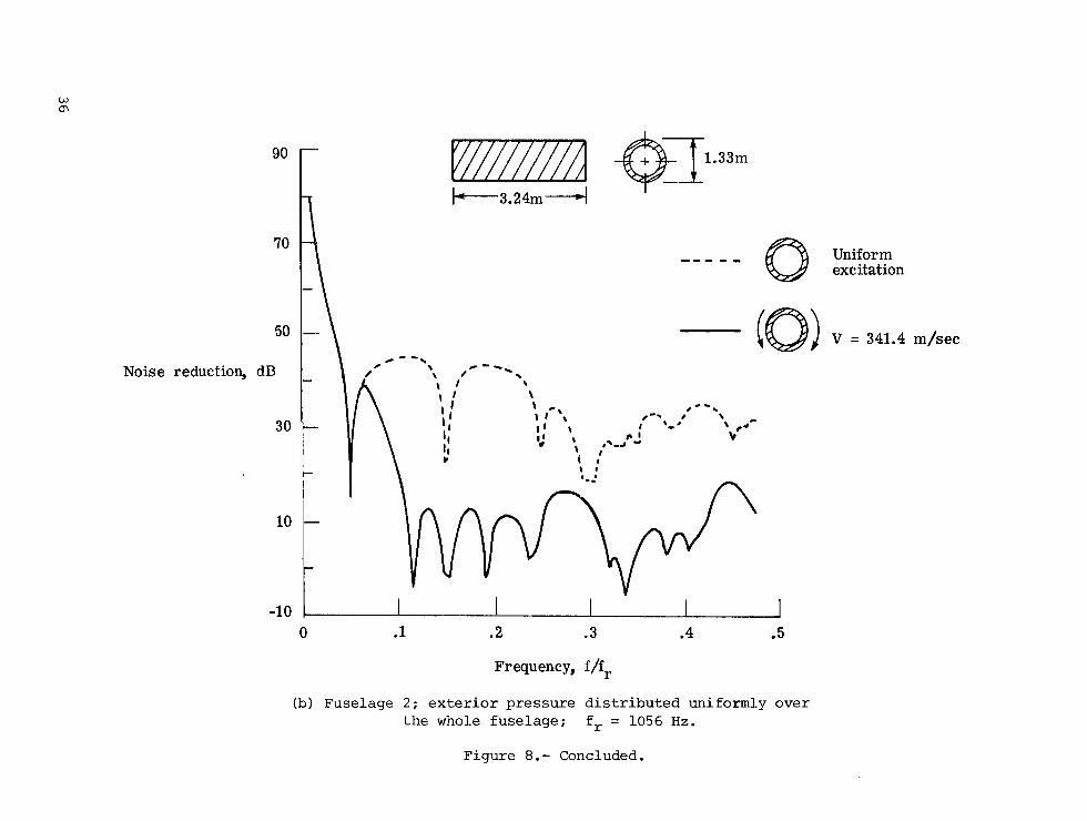
reduct ion is higher f o r uniform e x c i t a t i o n than f o r t h e case of e x c i t a t i o n with sweep ve loc i ty . For t h e case of uniform e x c i t a t i o n , covering the f u l l circum- ference of t h e fuse l age ( t h a t is , b 2 = n R and b l = 0 ) , t h e i n t e g r a l s Imi are zero except when n = 0 , and hence, f o r uniform e x c i t a t i o n , only n = 0 s t r u c t u r a l modes are e x c i t e d and t r ansmi t noise t o t h e fuselage i n t e r i o r . The d i p i n t h e noise-reduction curve a t t h e reference frequency f o r t he case of uniform e x c i t a t i o n i n f i g u r e 8 (a ) may be explained by t h e l a r g e number of s t r u c t u r a l modes near t h i s frequency as compared t o o t h e r f requencies , as shown i n f i g u r e 5. The d i p s i n t h i s curve below the reference frequency are due t o the presence of a c o u s t i c modes only. I n f i g u r e 8 ( b ) , f o r t h e frequency range shown, the no i se r educ t ion f o r uniform e x c i t a t i o n i s always h ighe r than it i s when s w e e p v e l o c i t y i s p r e s e n t . A comparison with f i g u r e 8 ( a ) shows t h a t t h i s behavior i s s i m i l a r t o t h a t of fuselage 1 i n t h e frequency range where ( f / f r ) < 0.5. From f i g u r e s 8 (a ) and 8 ( b ) , it i s seen t h a t t he e f f e c t of sweep v e l o c i t y on no i se reduct ion is q u i t e s i g n i f i c a n t , o f t e n making a d i f f e r e n c e of 25 dB i n comparison wi th uniform e x c i t a t i o n .
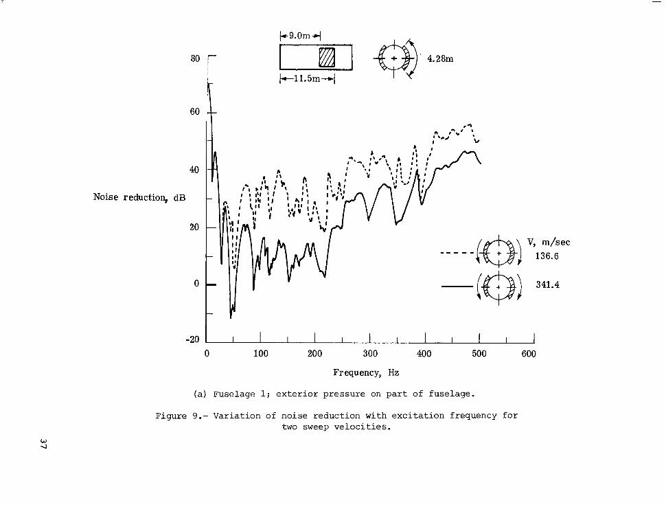
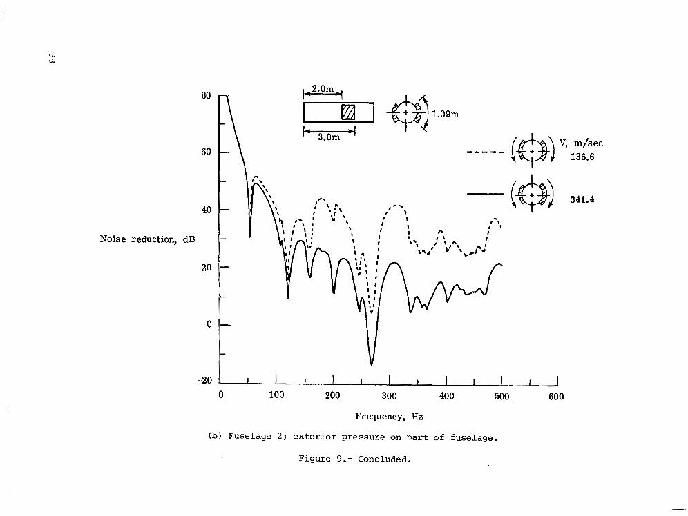
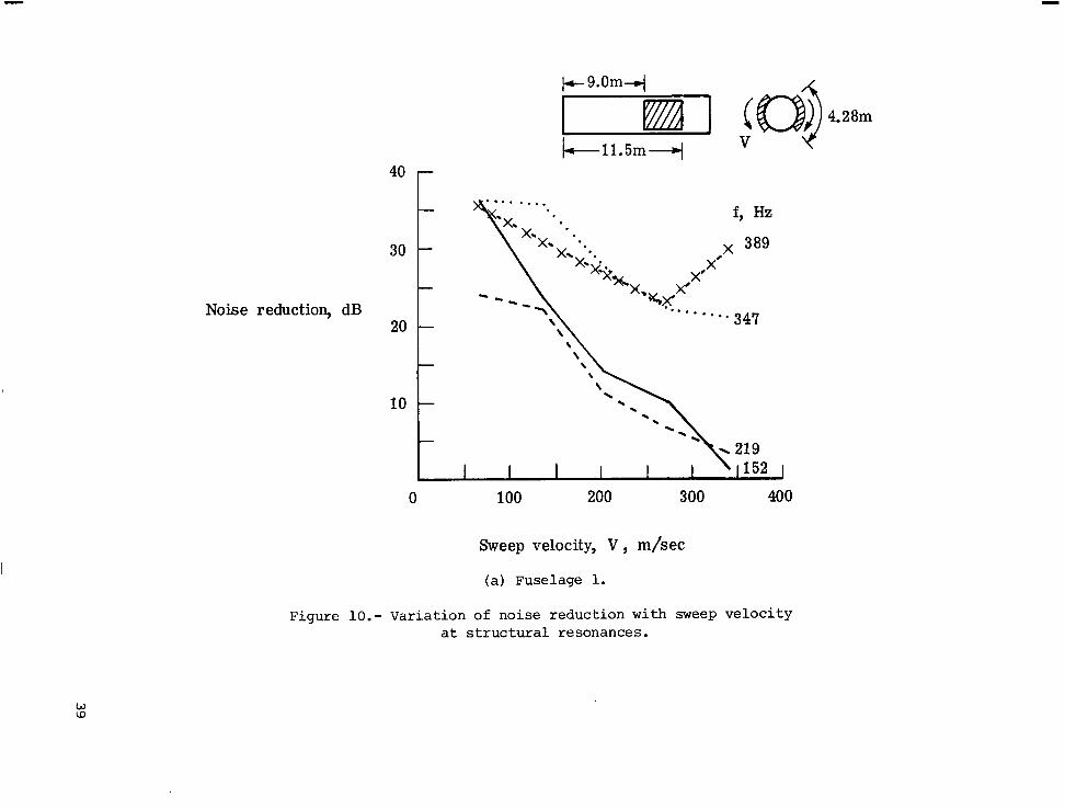
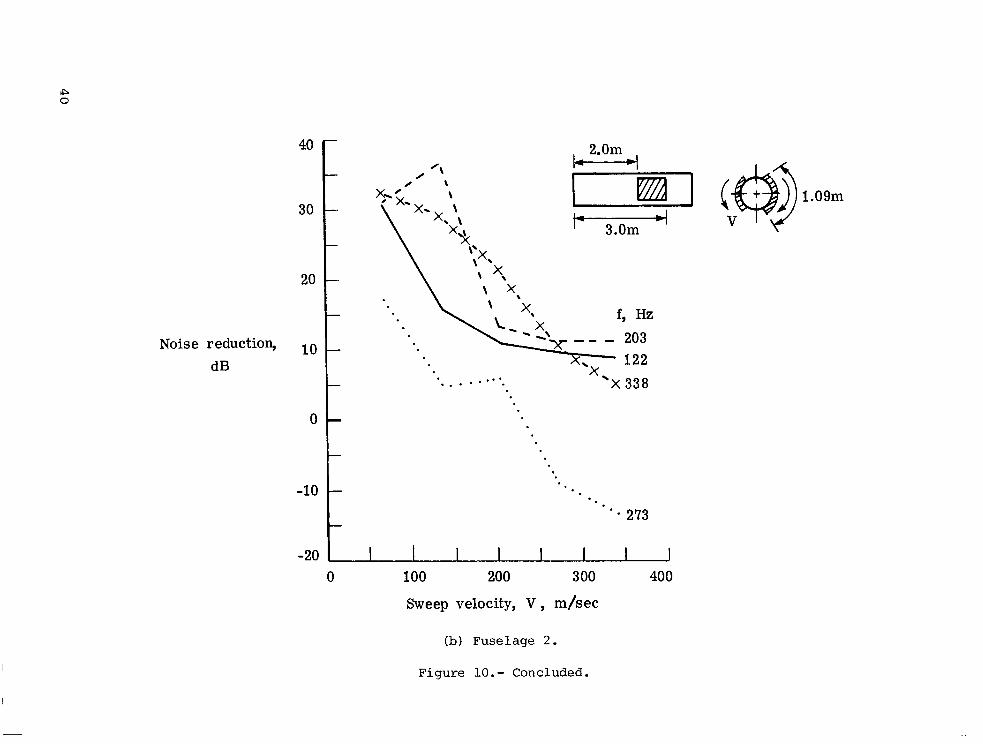
The v a r i a t i o n of no i se reduct ion with sweep v e l o c i t y i s shown i n f ig - u r e s 9 ( a ) and 9 ( b ) f o r fuse l age 1 and fuselage 2 , r e spec t ive ly . Only a p o r t i o n of t he fuselage su r face area i s exposed t o e x c i t a t i o n , i n t h e v i c i n i t y of t h e p r o p e l l e r p l ane , as shown i n f i g u r e s 9 ( a ) and 9 ( b ) . I t i s seen from t h e s e - f i g - u r e s t h a t , when the sweep v e l o c i t y i s reduced from 341.4 m / s e c t o 136.6 m / s e c , t h e noise reduct ion i n c r e a s e s by about 10 dB. These v e l o c i t i e s are chosen due t o t h e f a c t t h a t many p r o p e l l e r s have t i p speeds i n t h i s range. The s a m e t r end of noise reduct ion, decreasing with inc reas ing sweep v e l o c i t i e s , has been observed t o be gene ra l ly maintained over a broad range of sweep v e l o c i t i e s . This t r end i s shown i n f i g u r e s l O ( a ) and 1 0 ( b ) , f o r fuselage 1 and fuselage 2 , r e spec t ive ly , where the no i se reduct ion i s p l o t t e d a g a i n s t sweep v e l o c i t y a t a few rep resen ta t ive resonance frequencies .
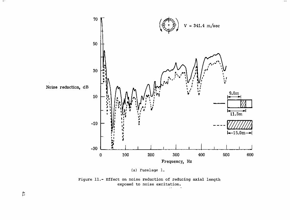
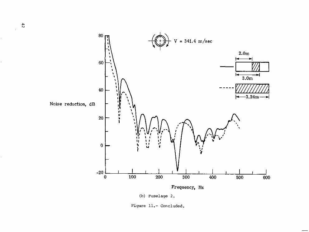
The e f f e c t of changing t h e a x i a l l eng th exposed t o no i se e x c i t a t i o n on noise reduct ion i s shown i n f i g u r e s l l ( a ) and l l ( b ) f o r fuselage 1 and fuse- lage 2 , r e spec t ive ly . I t i s seen from both the f i g u r e s t h a t a t most frequen- c ies the no i se reduct ion i s g r e a t e r by as much as 10 dE! when a s m a l l e r p o r t i o n of fuselage length i s sub jec t ed t o e x c i t a t i o n . An exception i s shown i n f i g - ure l l ( b ) a t about 270 Hz where the noise reduct ion i s s u b s t a n t i a l l y l e s s when a smaller length of fuse l age is exc i t ed . A s i nd ica t ed p rev ious ly , t h e s t ruc - t u r a l and a c o u s t i c modes with m = 2 and n = 2 have nea r ly the s a m e f r e - quencies, r e s u l t i n g i n a matching of t h e i r resonances and consequently a low noise reduct ion. This low no i se r educ t ion does not occur when t h e whole fuse- l age i s e x c i t e d because t h e m = 2 a x i a l modes are orthogonal t o the uniform e x c i t a t i o n d i s t r i b u t i o n . I t i s a l s o i n t e r e s t i n g t o note t h a t t he d i p s i n t h e noise-reduction curve i n f i g u r e l l ( a ) correspond with t h e modal f requencies discussed ear l ier where s t r u c t u r a l and acous t i c modal f requencies match.
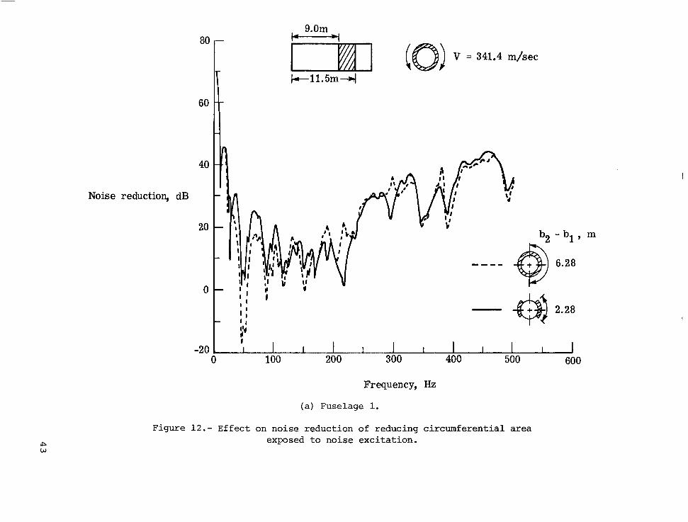
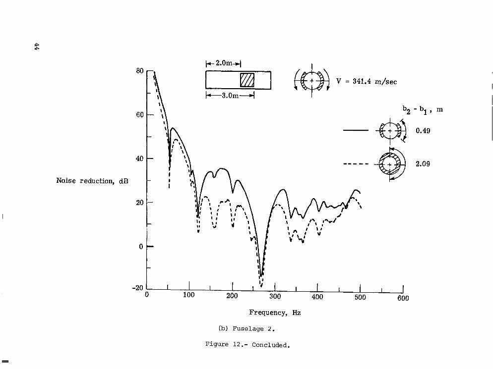
The e f f e c t of c i r c u m f e r e n t i a l p re s su re d i s t r i b u t i o n on no i se reduct ion is shown i n f i g u r e s 1 2 ( a ) and 1 2 ( b ) f o r fuselage 1 and fuse l age 2 , r e spec t ive ly . I n these f i g u r e s n o i s e r educ t ions are p l o t t e d f o r two d i f f e r e n t c i r cumfe ren t i a l areas exposed t o no i se e x c i t a t i o n , keeping the a x i a l p o r t i o n exposed t o no i se and t h e sweep v e l o c i t y constant . A comparison of t h e two curves i n f i g u r e 1 2 ( a ) shows t h a t t h e no i se reduct ion does n o t vary s u b s t a n t i a l l y with c i r cumfe ren t i a l
13
area f o r most f requencies . In f i g u r e 12 (b ) no ise reduct ion i s h igher by as much a s 20 dB when the c i r cumfe ren t i a l area exposed t o no i se i s reduced. These r e s u l t s i n d i c a t e t h a t , i n genera l , it i s important t o have a knowledge of t he d i s t r i b u t i o n of no i se i n o rde r t o determine p rope r ly the noise reduct ion i n a fuselage.
CONCLUDING REMARKS
The e f f e c t on no i se reduct ion of p r o p e l l e r no i se c h a r a c t e r i s t i c s has been s tudied f o r a twin-engine, p rope l le r -dr iven a i r c r a f t wi th t w o p r o p e l l e r s r o t a t - i n g i n oppos i te d i r e c t i o n s . The fuse lage i s modeled as a c y l i n d r i c a l s h e l l with s t r i n g e r s and r i n g frames, whose e f f e c t s are averaged over t h e fuse lage sur face . The mathematical model o f t he propeller no i se e x c i t a t i o n used i n t h i s s tudy inc ludes some of t he p r o p e l l e r no i se c h a r a c t e r i s t i c s such as p res su re 'waves sweeping around the fuse lage s idewa l l s due t o p r o p e l l e r r o t a t i o n and the loca l - i zed na tu re of e x c i t a t i o n with the h ighes t l e v e l s nea r t he p r o p e l l e r plane. The inf luence of t he p r o p e l l e r no ise c h a r a c t e r i s t i c s on the noise reduct ion i s s tudied .
The r e s u l t s of t h i s i n v e s t i g a t i o n show t h a t s u b s t a n t i a l changes i n noise reduct ion occurred when sweep v e l o c i t y and a r e a of fuse lage subjec ted t o noise e x c i t a t i o n w e r e changed. N o i s e r educt ion gene ra l ly decreased a s the sweep v e l o c i t y increased. Reducing the a r e a exposed t o e x c i t a t i o n gene ra l ly increased noise reduct ion. For the range of v a r i a b l e s s tud ied , d i f f e r e n c e s i n noise reduct ion of t he order of 10 t o 20 dB were observed.
Langley Research Center National Aeronaut ics and Space Administration Hampton, VA 23665 October 13, 1978
14
APPENDIX A
EQUATION OF MOTION OF THE FUSELAGE STRUCTURE
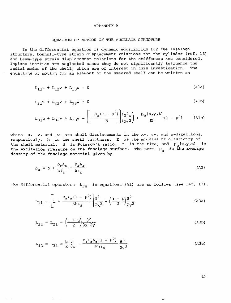
In t h e d i f f e r e n t i a l equat ion of dynamic equi l ibr ium f o r t h e fuselage s t r u c t u r e , Donne11-type s t r a i n displacement r e l a t i o n s f o r t h e cy l inde r ( r e f . 13) and beam-type s t r a i n displacement r e l a t i o n s f o r t h e s t i f f e n e r s are considered. Inplane i n e r t i a s are neglected s i n c e they do n o t s i g n i f i c a n t l y in f luence t h e r a d i a l modes of t h e s h e l l , which are of i n t e r e s t i n t h i s i n v e s t i g a t i o n . The equat ions of motion f o r an element of t h e smeared s h e l l can be w r i t t e n as
where u, v, and w are s h e l l displacements i n t h e x-, y-, and z -d i r ec t ions , r e spec t ive ly , h i s t h e s h e l l t h i ckness , E i s t h e modulus of e l a s t i c i t y of t h e s h e l l material, p i s Po i s son ' s r a t i o , t i s t h e t i m e , and p e ( x , y , t ) i s t h e e x c i t a t i o n p r e s s u r e on t h e fuse l age surface. The term pa i s t h e average d e n s i t y of t h e fuse l age m a t e r i a l given by
The d i f f e r e n t i a l Operators Lrs i n equat ions ( A l ) are as follows (see r e f . 13) :
i + u a 2 i 2 ) a x ay L12 = L21 = ~~
15
APPENDIX A
1-1 a 2 +
=22 = (+)G c
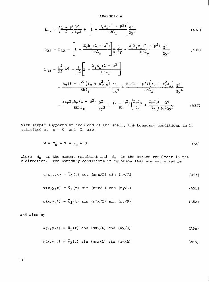
With s i m p l e suppor ts a t each end of t h e s h e l l , t he boundary condi t ions t o be s a t i s f i e d a t x = 0 and L a r e
where Mx i s t h e moment r e s u l t a n t and Nx i s t h e s t r e s s r e s u l t a n t i n the x-d i rec t ion . 'The boundary condi t ions i n equat ion ( A 4 ) a r e s a t i s f i e d by
v ( x , y , t ) = v l ( t ) s i n (mTrx/L) cos (ny/R) (A5b)
and a l s o by
v ( x , y , t ) = v 2 ( t ) s i n (m'mx/L) s i n (ny/R)
16
APPENDIX A
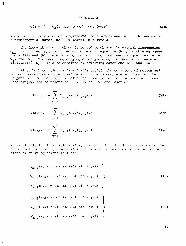
where m is t h e number of l o n g i t u d i n a l ha l f waves, and n i s the number of c i r cumfe ren t i a l waves, as i l l u s t r a t e d i n f i g u r e 2 .
The f r ee -v ib ra t ion problem is solved t o o b t a i n t h e n a t u r a l f requencies by p u t t i n g p e ( x , y , t ) equal t o zero i n equation ( A l c ) , combining equa-
r%ns ( A l ) and ( A s ) , and so lv ing t h e r e s u l t i n g simultaneous equat ions i n zll v and Gl. The same frequency equat ion y i e l d i n g t h e s a m e set of n a t u r a l f requencies
- Wm i s also ob ta ined by combining equat ions ( A l ) and (A6).
1'
Since both equa t ions (A5) and (A6) s a t i s f y t h e equat ions of motion and boundary condi t ion of t h e fuse l age s t r u c t u r e , a complete s o l u t i o n f o r t h e response of t h e s h e l l w i l l involve t h e summation of both sets of so lu t ions . Accordingly, t h e s o l u t i o n s f o r u, v, and w are taken as
where i = 1, 2. I n equa t ions (A7), t h e s u b s c r i p t i = 1 corresponds t o the set of s o l u t i o n s i n equa t ions (A5) and i = 2 corresponds t o the s e t of solu- t i o n s given i n equat ions (A6) and
Uml(x,y) = c o s (mnx/L) s i n (ny/R)
Vml(x,y) = s i n (mnx/L) c o s (ny/R)
Wml(x,y) = s i n (mnx/L) s i n (ny/R)
Um2(x,y) = cos (mnx/L) c o s (ny/R)
vm2(x,y) = s i n (mTx/L) s i n (ny/R)
Wm2(x,y) = s i n (mnx/L) cos (ny/R)
I 1
17
APPENDIX A
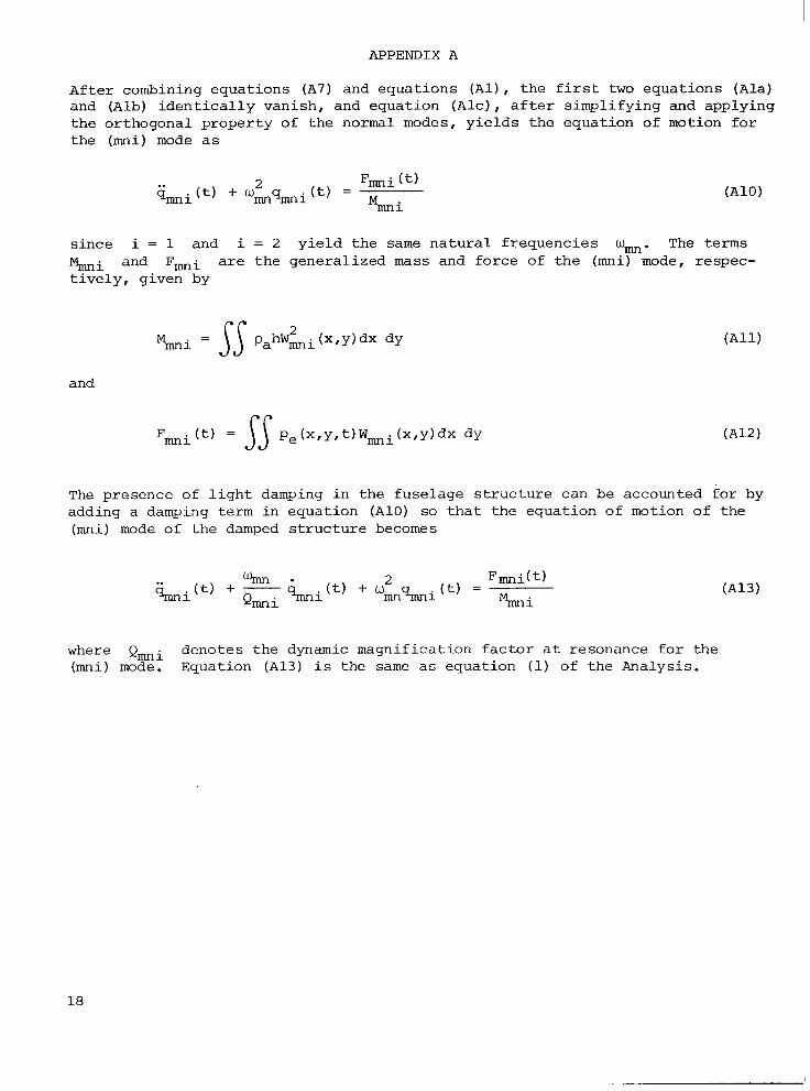
Af t e r combining equat ions ( A 7 ) and equat ions (AI), t h e f i r s t two equat ions ( A l a ) and (Alb) i d e n t i c a l l y vanish, and equat ion ( A l c ) , a f t e r s impl i fy ing and applying t h e or thogonal p rope r ty of t h e normal modes, y i e l d s t h e equat ion of motion f o r t he (mi) mode as
s ince i = 1 and i = 2 y i e l d t h e same n a t u r a l f requencies Wmn. The terms ki and F m i a r e t h e genera l ized m a s s and f o r c e of t h e (mni) mode, respec- t i v e l y , given by
and
The presence of l i g h t damping i n the fuse lage s t r u c t u r e can be accounted f o r by adding a damping term i n equat ion (A101 so t h a t t he equat ion of motion of t he (mni) mode of the damped s t r u c t u r e becomes
where (mni) mode. Equation (A13) i s the same a s equat ion (1) of t h e Analysis.
Qmi denotes t h e dynamic magnif icat ion f a c t o r a t resonance f o r t he
18
APPENDIX B
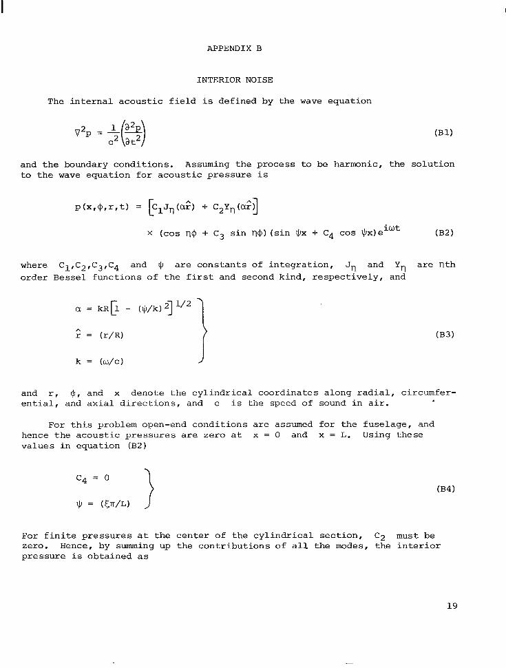
INTERIOR NOISE
The i n t e r n a l a c o u s t i c f i e l d i s def ined by the wave equat ion
and t h e boundary condi t ions . Assuming t h e process t o be harmonic, t he s o l u t i o n to t h e wave equat ion €or a c o u s t i c p re s su re i s
where C1,C2,C3,C4 and $ are cons tan t s of i n t e g r a t i o n , Jrl and Y,, a r e n t h order Bessel func t ions of t h e f i r s t and second kind, r e s p e c t i v e l y , and
= ( r / R )
k = (w/c) J
and r , $, and x denote t h e c y l i n d r i c a l coord ina tes along r a d i a l , circumfer- e n t i a l , and a x i a l d i r e c t i o n s , and c i s the speed of sound i n a i r .
For t h i s problem open-end cond i t ions a r e assumed f o r t he fuse lage , and hence t h e a c o u s t i c p r e s s u r e s are zero a t x = 0 and x = L. Using these va lues i n equat ion ( B 2 )
For f i n i t e p r e s s u r e s a t t h e c e n t e r of t he c y l i n d r i c a l s e c t i o n , C 2 must be zero. Hence, by summing up t h e c o n t r i b u t i o n s of a l l t h e modes, t he i n t e r i o r p re s su re i s obta ined as
19
APPENDIX B
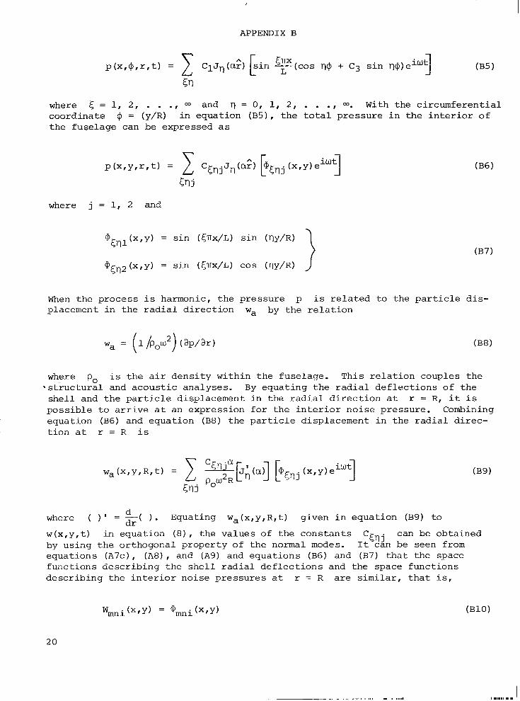
where 5 = 1, 2 , . . ., and r) = 0, 1, 2 , . . ., 00. With the c i r cumfe ren t i a l coord ina te @ = (y/R) i n equat ion (B5), t h e t o t a l p re s su re i n t h e i n t e r i o r o f t he fuse lage can be expressed as
where j = 1, 2 and
When the process i s harmonic, t he p re s su re p i s r e l a t e d t o the p a r t i c l e d i s - placement i n the r a d i a l d i r e c t i o n wa by the r e l a t i o n
where po i s t h e a i r d e n s i t y within t h e fuse lage . This r e l a t i o n couples t h e By equat ing t h e r a d i a l d e f l e c t i o n s of t he
s h e l l and t h e p a r t i c l e displacement i n the r a d i a l d i r e c t i o n a t r = R, it i s p o s s i b l e t o a r r i v e a t an expression f o r t he i n t e r i o r no i se pressure . Combining equat ion (B6) and equat ion (B8) the p a r t i c l e displacement i n the r a d i a l d i r ec - t i o n a t r = R i s
- s t r u c t u r a l and a c o u s t i c analyses .
d where ( ) ' = z( ) . Equating wa(x,y,R,t) given i n equat ion (B9) to
w(x ,y , t ) i n equat ion (8) , t he va lues of t he cons t an t s can be obta ined by us ing t h e or thogonal p rope r ty of t he normal modes. I t can be seen from equat ions ( A ~ c ) , (A8), and (A9) and equat ions (B6) and ( B 7 ) t h a t t he space func t ions desc r ib ing the s h e l l r a d i a l d e f l e c t i o n s and the space func t ions desc r ib ing the i n t e r i o r no ise p re s su res a t r = R a r e s i m i l a r , t h a t is ,
20
APPENDIX B
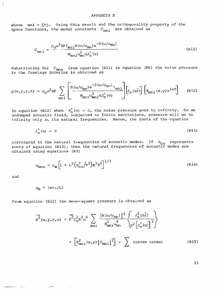
where mi = c u j . space func t ions , t h e modal c o n s t a n t s Cmi are obtained as
Using t h i s r e s u l t and t h e o r thogona l i ty p rope r ty of t h e
S u b s t i t u t i n g f o r C m i from equat ion ( B l l ) i n equation (B6) t he noise p re s su re i n t h e fuse l age i n t e r i o r i s obtained as
In equation (B12) when undamped a c o u s t i c f i e l d , subjected t o f i n i t e e x c i t a t i o n s , p re s su re w i l l g o t o i n f i n i t y only a t i t s n a t u r a l f requencies .
JA(a) = 0, t h e no i se p re s su re goes t o i n f i n i t y . .In an
Hence, t h e r o o t s of t h e equation
correspond t o t h e n a t u r a l f r equenc ie s of a c o u s t i c modes. I f r e p r e s e n t s
obtained using equa t ions (B3) roots of equation (B13), then t h e n a t u r a l f requencies o f a c o u s t i c I?s modes are
and
% = (mrc /L)
From equat ion ( B 1 2 ) t h e mean-square p re s su re i s obtained as
APPENDIX B
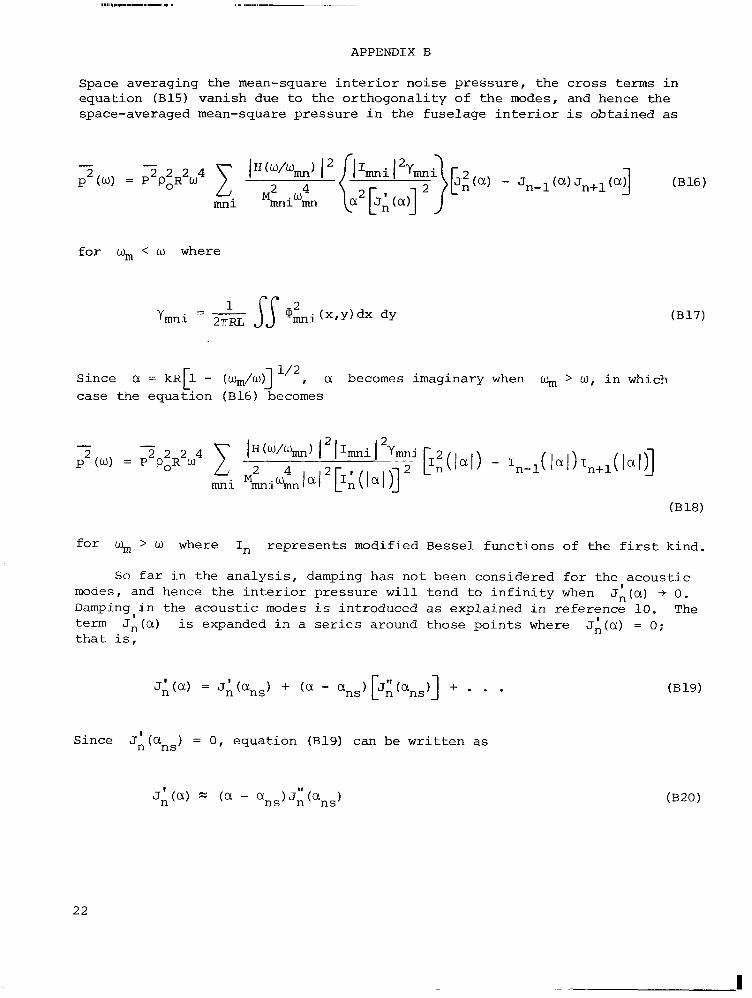
Space averaging the mean-square i n t e r i o r no ise pressure , t h e c ros s t e r m s i n equat ion (Bl5) vanish due t o t h e o r thogona l i ty of t h e modes, and hence the space-averaged mean-square p re s su re i n t h e fuse lage i n t e r i o r i s obta ined as
f o r wm < w where
Since a = kR[1 - (wm/w)] a becomes imaginary when k+,, > w, i n which case the equat ion (B16) becomes
f o r wm > w where In rep resen t s modified B e s s e l func t ions of t he f i r s t kind.
So f a r i n t h e a n a l y s i s , damping has n o t been considered f o r t h e a c o u s t i c JA(a) -+ 0 . modes, and hence t h e i n t e r i o r pressure w i l l t end t o i n f i n i t y when
Damping i n the a c o u s t i c modes i s introduced as explained i n re ference 10. The term Jn(a) is expanded i n a series around those p o i n t s where JA(a) = 0; t h a t i s ,
1
Since J 1 ( a ) = 0, equat ion (B19) can be w r i t t e n as n ns
22
APPENDIX B
where the series i n equat ion (B19) i s t runcated a f t e r t h e second term. For s m a l l values of ( a - ans),
a2 - a2 = 2ans(a - ans) n s
2 - and an, - wmns 2 2 R2
S u b s t i t u t i n g a = w -[1 - (LI+&II)~] C 2 C
equation ( B 2 1 ) it is seen t h a t
Using the r e l a t i o n s h i p s i n equat ions (B20) and (B22) ,
1 4
where a -f ans. I n s e r t i n g t h e a c o u s t i c dynamic magnif icat ion f a c t o r Qac and allowing w -+ wmS, equat ion (B23) can be w r i t t e n as
S u b s t i t u t i n g the value of t i o n (B16), t h e space-averaged mean-square i n t e r i o r noise p re s su re i n t h e v i c i n i t y of a c o u s t i c resonances i s obtained as
(l/a2) [JA(a)] given i n equat ion (B24) i n t o equa-
f o r w -+ wmS.
23
REFEmNCES
1. Hubbard, Harvey H.; and R e g i e r , Arthur A.: Free-Space O s c i l l a t i n g P res su res N e a r t h e T i p s o f Rota t ing P r o p e l l e r s . NACA Rep. 996, 1950.
2. Deming, Ar thur F.: P r o p e l l e r Rota t ion Noise Due t o Torque and Thrus t . NACA T N 747, 1940.
3. Regier , Arthur A.; and Hubbard, Harvey H.: S t a t u s o f Research on P r o p e l l e r Noise and Its Reduction. J. Acoust. SOC. America, vol . 25, no. 3, May 1953, pp. 395-404.
4. Franken, P e t e r A.; Kerwin, Edward M . , Jr.; and t h e S t a f f o f Bo l t Beranek and Newman, Inc. : Methods o f F l i g h t Vehicle Noise P red ic t ion . WADC Tech. Rep. 58-343, ASTIA Doc. No. AD 205 776, U.S. A i r Force, Nov. 1958.
5. Marte, Jack E.; and Kurtze, Donald W. : A R e v i e w o f Aerodynamic N o i s e From P r o p e l l e r s , Rotors , and L i f t Fans. Tech. R e p . No. 32-1462, Jet Propuls ion Lab . , C a l i f o r n i a I n s t . Technol., Jan. 1, 1970. ( A v a i l a b l e as NASA CR-107563.)
6. Ungar, E r i c E . ; Wilby, John F.; and B l i s s , Donald B., e t a l . : A R e v i e w o f Methods f o r Es t imat ion of Aeroacoust ic Loads on F l i g h t Vehicle Surfaces . AFFDL-TR-76-91, U . S . A i r Force, Feb. 1977. (Avai lab le from DDC as AD A042 783.)
7 . Hanson, Donald B.: N e a r F i e l d Noise of High T i p Speed P r o p e l l e r s i n Forward F l i g h t . AIAA Paper No. 76-565, J u l y 1976.
8. Wilby, J. F.; and Scharton, T. D.: Acous t ic Transmission Through a Fuselage Sidewall . NASA CR-132602, 1975.
9. Koval, L. R.: On Sound Transmission I n t o a Thin C y l i n d r i c a l S h e l l Under "F l igh t Conditions." J. Sound & V i b . , vo l . 48, no. 2 , Sept . 2 2 , 1976, pp. 265-275.
10. Cockburn, J. A.; and J o l l y , A. C.: S t ruc tu ra l -Acous t i c Response Noise Transmission Losses and I n t e r i o r Noise Levels of an A i r c r a f t Fuselage Exci ted by Random Pres su re F ie lds . Tech. Rep. AFFDL-TR-68-2, U.S. A i r Force, Aug. 1968.
11. Mixson, John S.; Barton, C. Kearney; and V a i c a i t i s , R i m a s : I n v e s t i g a t i o n o f I n t e r i o r Noise i n a Twin-Engine L igh t A i r c r a f t . J. A i r c r . , vo l . 15, no. 6 , A p r . 1978.
1 2 . V a i c a i t i s , R.; and McDonald, W.: Noise Transmission I n t o a L igh t A i r c r a f t . AIAA Paper 78-197, Jan. 1978.
24
13. Mikulas, Martin M., Jr.; and McElman, John A.: On Free Vibrat ions of E c c e n t r i c a l l y S t i f f e n e d Cy l ind r i ca l S h e l l s and F l a t P l a t e s . NASA TN D-3010, 1965.
14. Beranek, Leo L., ed.: Noise and Vibrat ion Control. M c G r a w - H i l l Book Co., Inc., c.1971.
15. Sewall, John L.; and Naumann, Eugene C.: An Experimental and Ana ly t i ca l Vibrat ion Study of Thin C y l i n d r i c a l S h e l l s With and Without Longitudinal S t i f f e n e r s . NASA T N D-4705, 1968.
25
TABLE I.- STRUCTURAL DETAILS OF THE FUSELAGES
Dimension
Length, L, m
D i a m e t e r , D, m
Skin th i ckness , h, mm
S t r i n g e r t h i ckness , hs, mm
S t r i n g e r depth, ds, c m
S t r i n g e r f l ange width, bs, c m
S t r i n g e r spacing, 2 , c m
Frame th i ckness , hr , mm
Frame depth , d r , c m
Frame f l ange width, b,, c m
Frame spacing, l,, c m
Fuselage 1
15.00
4.00
1.00 ~
1.50
4.00
2.00
1.50
10.00
4.00
40.00
Fuselage
3.24
1.34
.64 . .
0.64
1.91
1.42
7.62
1.52
3.81
1.91
20.32
2 S t i f f e n e r cross s e c t i o n s
26
TABLE 11.- PROPERTIES OF MATERIALS
Modulus of e l a s t i c i t y of sk in , s t r i n g e r , and frame, E,E,,E,, Pa . . . . . . . . . . . . . . . . . . . . . . . . . . . 0.71 x i o l1
Poisson ' s ra t io , p . . . . . . . . . . . . . . . . . . . . . . . . . 0.33
Density of sk in , s t r i n g e r , and f r a m e material , PIP,, P,, kg/m3 . . . . . . . . . . . . . . . . . . . . . . . . . 0.27 x lo4
Density of a i r , Po, kg/m3 . . . . . . . . . . . . . . . . . . . . . . 1.25
Veloci ty of sound i n a i r , c , m / s e c . . . . . . . . . . . . . . . . . . 341.4
Magnification f a c t o r f o r s t r u c t u r e , Q m i . . . . . . . . . . . . . . 50
Magnification factor for a i r , Qa, . . . . . . . . . . . . . . . . . . 25
27
Ring f rame
Stringer
(a) Fuselage.
Plane of symmetry
2 -
Propeller
@- (b) P rope l l e r no i se d i s t r i b u t i o n .
Figure 1.- Models showing fuse lage and p r o p e l l e r no ise d i s t r i b u t i o n . All dimensions a r e i n meters.
Figure 2.- S t r u c t u r a l mode shapes o f a c y l i n d r i c a l s h e l l . m a x i s ; n , number of e l a s t i c f u l l waves around cy l inde r circumference.
i n d i c a t e s number of e l a s t i c ha l f waves along cy l inde r
29
n = O n = 2 n = 3 s = l s = l s = l
800
700
600
500
400
300
200
100
n = 4 s = l
- o---o--- 0 Experiment (ref. 15)
-
- - - - - -
I I I 1 1 I 1 . 1 I 1 I _ . J
n = O n = 2 s = 2 s = 2
800
700
600
500
400
300
200
100
Figure 3 . - Typical c i r cumfe ren t i a l and r a d i a l a c o u s t i c node p a t t e r n s . n i n d i c a t e s number of c i r cumfe ren t i a l f u l l waves; s, number of rad ia l waves.
- o---o--- 0 Experiment (ref. 15)
-
- - - - - -
I I I 1 1 I 1 . 1 I 1 1 - J
Frequency, Hz
Figure 4.-
Circumferential waves, n
Comparison of p red ic t ed and measured n a t u r a l frequencies.
30
m
Frequency, Hz
600
500
400
300
200
100
0 2 4 6 8 1 0
Circumferential waves, n
(a) Fuselage 1.
m
0 2 4 6 8 1 0
Circumferential waves, n
(b) Fuselage 2 .
Figure 5.- Modal f requencies of fuse lage s t r u c t u r e .
31
W N
500
Frequency, Hz 'I' 200
100
30
Frequency, Hz 400 300 - -
30 20 - - 40 1" -
1 I I I I
m m
500
400
-
Frequency, 300 Frequency,
HZ 200 - 200 Hz
100 1 s = 2 100 1- s = 3
1 0 1 2 3 4 5 6 7 8
Circumferential waves, n Circumferential waves, n
( a ) Fuselage 1.
Figure 6.- Acoustic modal f requencies of fuselage i n t e r i o r space. m i nd ica t e s number of longi tudina l half waves; n , number of c i rcumferent ia l f u l l waves; s, number of r a d i a l waves.
m m
500
400
300
200
100
Frequency, Hz
~
0 1 2 3 4 5
Circumferential waves, n
(b) Fuselage 2.
Frequency, 300
Hz 200 1 100 1 s = l - 0 1 2 3 4 5
Circumferential waves, n
Figure 6. - Concluded.
W W
W Ip
Nois e reduction,
90
70
dB
50
30
r Spectrum for
0 fl and its harmonics
0 ff and its harmonics
80
60
40
20 Noise
reduction, dB
0
-20
m
Uniform excitation
-- - - -
(0) V = 341.4 m/sec
-40 0 .2 .4 .6 .8 1.0 1.2 1.4 1.6
Frequency, f/fr
(a) Fuselage 1; ex te r io r pressure d is t r ibu ted uniformly over the whole fuselage; f r = 347 Hz.
Figure 8.- Variation of noise reduction with exc i t a t ion frequency with and without sweep velocity.
90
70
50
Noise reduction, dB
30
10
-10
1.33m
I +3.24m--d
- \ Uniform excitation
--- - _
0 .1 .2 .3 .4 .5
Frequency, f/fr
(b) Fuselage 2 ; e x t e r i o r pressure d i s t r i b u t e d uniformly over t he whole fuselage; f, = 1056 H z .
V = 341.4 m/sec
Figure 8.- Concluded.
80
60
40
Noise reduction, dB
20
0
-20
0 7 , 4.28m
V, m/sec 136.6
341.4
I
0 100 200 300 400 500 600
Frequency, Hz
(a) Fuselage 1; ex te r io r pressure on p a r t of fuselage.
Figure 9.- Variation of noise reduction with exc i ta t ion frequency fo r two sweep ve loc i t ies .
W 03
80
60
40
Noise reduction, dB
20
0
-20
-b,
t-t I 1 I I
I I I I 1 I I I I I I I 0 100 200 300 400 500 600
Frequency, Hz
(b) Fuselage 2; e x t e r i o r pressure on p a r t of fuselage.
Figure 9.- Concluded.
Noise reduction, dB
40 r
30
20
10
\\
I- .-\. 219
0 100 200 300 400
Sweep velocity, V , m/sec
(a) Fuselage 1.
Figure 10.- Variation of noise reduction with sweep ve loc i ty a t s t r u c t u r a l resonances.
w 10
Ip 0
30
20
10
40 r -
-
-
-
-
- -
0 -
-
, 2.0m ,
Noise reduction, dB
-10 1
'\ 0
1.09m
'. 273
-20 0 100 200 3 00 400
Sweep velocity, V , m/sec
(b) Fuselage 2.
Figure 10.- Concluded.
70
50
30
Noise reduction, dB
10
-10
-30
V = 341.4 m/sec
I I I I
U 11.5m
k l 5 . 0 m - 4
I I I I I I I
0 100 200 300 400 500 600 Frequency, Hz
(a) Fuselage 1.
Figure 11.- Effec t on noise reduction of reducing a x i a l length exposed t o noise exc i ta t ion .
. *
80
60
40
Noise reduction, dB
20
0
-20
V = 341.4 m/sec
2.0m H -m w
3.0m
-----
I I I I I I I I I
Frequency, Hz
(b) Fuselage 2.
Figure 11.- Concluded.
9.0m M
P W
80
60
40
Noise reduction, dB
20
0
-20
- b p m
6.28
- -@ 2.28
# I 1 I I I 1 I 1 I I I
100 200 300 400 500 600
Frequency, Hz
(a) Fuselage 1.
Figure 12.- Effect on noise reduction of reducing circumferential area exposed to noise excitation.
80
60
40
Noise reduction, dB
20
0
-20
\
v
I I I I I I I I J 200 300 400 500 600 0 100
Frequency, Hz
(b) Fuselage 2.
Figure 12.- Concluded.
0.49
2.09
2. Government Accession No. L= - I . Report NO.
NASA TP-1325
4. Title and Subtitle
A THEORETICAL INVESTIGATION OF NOISE REDUCTION THROUGH THE CYLINDRICAL FUSELAGE O F A TWIN-ENGINE, PROPELLER-DRIVEN AIRCRAFT
- _ _ 3. Recipient's Catalog No.
17. Key Words (Suggested by Author(s))
A c o u s t i c s Noise reduct ion I n t e r i o r no i se C y l i n d r i c a l fuselage Propeller noise
5. Report Date- ~
D e c e m b e r 1978 6. Performing Organization Code
-
- ..
' ' I 18. Distribution Statement
U n c l a s s i f i e d - U n l i m i t e d
Subject C a t e g o r y 7 1 ___ . -
. - -
8. Performing Organization Report No.
L-12225
19. Security Classif. (of this report)
U n c l a s s i f i e d ~ ~~
10. Work Unit No.
505-09-2 3-01 ~~
11. Contract or Grant No.
20. Security Classif. (of this page) 21. NO. of Pages 22. Rice'
U n c l a s s i f i e d 44 $4.50
. .
~ -. - 13. Type of Report and Period Covered
12. Sponsoring Agency Name and Address I Technical Paper
N a t i o n a l A e r o n a u t i c s and Space A d m i n i s t r a t i o n Washington, DC 20546
National Aeronautics and THIRD-CLASS BULK R A T E
Space Administration
Washington, D.C. 20546 Official Business
Penalty for Private Use, $300
Postage and Fees Paid - I National Aeronautics and Space Administration