Page 1
RESEARCH PAPER
A thermo-mechanical damage model for rock stiffnessduring anisotropic crack opening and closure
Cheng Zhu • Chloe Arson
Received: 18 May 2013 / Accepted: 9 October 2013
� Springer-Verlag Berlin Heidelberg 2013
Abstract A thermodynamic framework is proposed to
couple the effect of mechanical stress and temperature on
crack opening and closure in rocks. The model is based on
continuum damage mechanics, with damage defined as the
second-order crack density tensor. The free energy of the
damaged rock is expressed as a function of deformation,
temperature, and damage. The damage criterion captures
mode I crack propagation, the reduction in toughness due
to heating, and the increase in energy release rate with
cumulated damage. Crack closure is modeled through
unilateral effects produced on rock stiffness. The model
was calibrated and verified against published experimental
data. Thermo-mechanical crack opening (resp. closure)
was studied by simulating a triaxial compression test (resp.
uniaxial extension test), including a thermal loading phase.
The degradation of stiffness due to tensile stress and
recovery of stiffness induced by both mechanical and
thermo-mechanical unilateral effects are well captured.
The thermo-mechanical energy release rate increases with
thermal dilation and also decreases with ambient temper-
ature. It was observed that there is a temperature threshold,
below which the rock behaves elastically. A parametric
study also showed that the model can capture hardening
and softening during thermo-mechanical closure (for spe-
cific sets of parameters). These numerical observations
may guide the choice of rock material used in geotechnical
design, especially for nuclear waste disposals or com-
pressed-air storage facilities.
Keywords Continuum damage mechanics �Damage-induced anisotropy � Rock constitutive behavior �Thermo-mechanical couplings � Unilateral effect
1 Introduction
Most of the research on rock mechanics is motivated by
societal needs such as energy production, energy storage,
and waste disposal. Safety and sustainability are key issues
in the design of the underground geotechnical facilities and
the foundations of structures needed to sustain the fuel
cycle. Design is based on the careful use of constitutive
models formulated according to theoretical requirements
and/or experimental observations [6, 31]. In particular,
crack initiation and propagation is a critical concern
[27, 60]. In addition to mechanical damage, nuclear waste
repositories and geothermal systems are exposed to sig-
nificant temperature gradients over time. Radioactive
packages disposed in the repositories release heat with an
exponent decay of power, responsible for a long-term
increase in the temperature of the surrounding rock mass
[56]. The dramatic changes in temperature associated with
geothermal reservoir exploitation also affect rock proper-
ties [67]. This raises the necessity to formulate the reliable
thermo-mechanical damage models for rocks.
Thermo-mechanical couplings are of primary impor-
tance in many geomaterials. In clay for instance, temper-
ature changes affect stiffness and deformation mostly
through thermo-hydro-mechanical couplings: Temperature
affects the density and viscosity free and adsorbed water
[50]. It is well-known that normally consolidated and
overconsolidated clays exhibit different thermoplastic
behaviors under thermo-mechanical stress paths [37]. The
critical state theory was combined with thermo-plastic soil
behavior models [38] in order to predict macroscopic
C. Zhu � C. Arson (&)
School of Civil and Environmental Engineering, Georgia
Institute of Technology, Atlanta, GA, USA
e-mail: [email protected]
C. Zhu
e-mail: [email protected]
123
Acta Geotechnica
DOI 10.1007/s11440-013-0281-0
Page 2
effects of temperature changes. Long-term thermo-
mechanical behavior of in-situ clay was investigated
through a chemo-thermo-plastic model [39] thorough
experimental studies enabled relating soil physical prop-
erties (e.g., friction angle, permeability) to soil macro-
scopic thermo-mechanical properties (e.g., elastic moduli)
[8, 49]. The structure of the porous space in the medium is
a significant factor that has been accounted for in many
thermo-hydro-mechanical coupled models. Description of
heat transfer in the porous space adds to the difficulty of
such formulations: Heat is exchanged by convection and
conduction, while the viscosity of pore fluids is tempera-
ture-dependent [73]. In addition, evaporation and conden-
sation may affect the transport of heat [25].
Thermo-mechanical stress gradients can originate vari-
ous micro-structure changes, leading to various material
property changes. Chain force models are appropriate for
granular materials [15]. For rocks, fracture mechanics
provides a powerful theoretical framework when the crack
propagation mode is known [48]. In fact, relating micro-
scopic processes (such as void nucleation, mode I crack
opening, and linkage of shear cracks) to macroscopic rock
properties (stiffness, permeability) is a challenging issue
[58]. Coupled processes impacting both physical and
mechanical properties were studied experimentally, both in
the laboratory and in situ [19]. Of particular interest are the
observations made to relate microstructure and physical
properties [26, 47], damage and density [87], porosity and
permeability [24, 57, 83], crack density and electrical
conductivity [19], damage and wave velocity [12, 71].
Studies were also dedicated to the response of rock under
frost action [59]. Large-scale in-situ tests were mainly
carried out to monitor the evolution of thermo-mechanical
damage [51] and study the variation of physical properties
like permeability [44, 72] under thermo-mechanical
effects. It is generally observed that mechanical properties
of rocks such as elastic moduli [30, 82], compressive
strength [43, 65, 84], or tensile strength [34], as well as
cohesion and friction angle [56], and fracture toughness
[68] decrease when temperature increases. The trends
expected for specific rock types are summarized in [32].
In continuum damage mechanics (CDM), the strain
energy loss due to crack propagation is used to compute
damaged stiffness and deformation. This approach is
purely energetic and does not require a geometric
description of the crack pattern. The second-order crack
density tensor [45] is particularly well-suited to evaluate
damaged elastic properties of a solid with non-interacting
cracks. Closure of tensile cracks allows recovery of com-
pressive strength and not tensile strength. These so-called
unilateral effects were studied in detail by Mazars et al.
[66] for concrete. A way of formulating the unilateral
condition for active/passive damage was proposed in [11].
The anisotropic mechanical model of crack closure was
later extended to account for frictional sliding at crack
faces [28]. Various models were proposed to predict
thermo-mechanical damage, but most of these models
partially uncouple thermal and mechanical effects, so that
damage does not truly depend on temperature variations,
but rather on thermo-mechanical stress [88]. In salt rock,
damage is associated with a crack-induced volumetric
deformation, captured by a ‘‘dilatancy boundary’’ [35, 40].
This class of models (see also [13]) do not capture stiffness
changes and could not predict damage-induced anisotropy
in a sedimentary rock.
In this study, a thermodynamic framework based on
CDM is proposed to model the effects of thermo-
mechanical crack opening and closure on rock stiffness.
Section 2 presents a state of the art of laboratory obser-
vations and thermodynamic models for thermo-mechanical
damage in rock. The theoretical framework of the proposed
constitutive model is explained in Sect. 3, which puts the
emphasis on the assumptions made to express the damage-
driving force. The model was calibrated and verified
against published experimental data, and the results are
presented in Sect. 4. Section 5 presents the simulations of
different stress paths, including crack opening and closure
under both mechanical and thermo-mechanical stresses.
The same stress paths were then simulated for different
types of rocks, and the results are discussed in Sect. 6.
2 State of the art: thermo-mechanical damage in rock
2.1 Experimental assessment of thermo-mechanical
damage in rock
Rock thermo-mechanical behavior was investigated with a
variety of stress paths, both at laboratory scale and field
scale. Different types of mechanical loading conditions
were considered, including monotonic/cyclic, uniaxial/tri-
axial, short-term/long-term, and drained/undrained. Table 1
provides the strength and Young’s modulus of rocks of
interest for geological storage purposes. Rock samples were
tested in the laboratory under different thermo-mechanical
stress paths, mainly (1) a temperature-controlled mechani-
cal loading, or (2) a heating phase followed by a mechanical
loading, or (3) a heating phase followed by a relaxation
period (until the temperature of the sample reached room
temperature) followed by a mechanical loading. Most of the
experimental results reported in the literature focus on rock
compressive strength. Temperature changes were limited to
less than 1,000 �C to prevent any chemical change in rock
minerals. Most often, rocks were subjected to a heating
phase. To the authors’ best knowledge, only granite and tuff
were studied upon cooling. Rock stiffness tends to increase
Acta Geotechnica
123
Page 3
(resp. decrease) upon cooling (resp. heating). Granite has
the highest compressive strength among all the rocks tested.
In gabbro, there exists a critical temperature above which
drastic change in mechanical properties occur [47]. Con-
fined salt rock is subject to complex time-dependent
microscopic processes, such as dislocation, glide, and
cross-slip. At the bulk scale, coupled processes make it
challenging to discriminate visco-plastic (dislocation-
induced) deformation and damage (crack-induced) defor-
mation. Overall, creep processes in salt rock result in much
larger deformation at failure compared to other types of
rock [82].
2.2 Thermo-mechanical damage models for rock:
continuum damage mechanics approaches
Micro-mechanical damage models [22, 54] assume that the
rock representative element volume (REV) is populated
with a given distribution of cracks characterized by a
specific shape (usually, spherical, penny-shaped, or ellip-
soidal cracks). Assumptions on the shape and density of
cracks allow to express explicitly the strain concentration
tensor and, further, to derive the theoretical expression of
the Helmholtz free energy of the rock solid skeleton. For
dilute distributions of cracks, the self-consistent method
proved to provide an efficient scheme to model the loss of
stored elastic deformation energy induced by cracking. If
microscopic cracks open in pure mode I, i.e., if the crack
displacement vector is normal to the crack planes, the only
damage variable needed to express the dissipation of
energy associated with the degradation of elastic moduli is
the second-order crack density tensor, defined by Kacha-
nov [45] as follows:
X ¼XN
k¼1
dknk � nk ð1Þ
In which the REV is assumed to contain N planar cracks
with a normal direction nk and a volumetric fraction dk.
Table 1 State of the art: experimental assessment of thermo-mechanical damage in rock
Material Experimental test T (�C) Peak stress
rP (MPa)
Strain at peak
stress eP
Stiffness
(GPa) (high
T– low T)
References
Limestone Uniaxial compression test without cooling 25–800 25–110 0.005–0.013 3.2–17.8 (E) [85]
Uniaxial compression test after cooling 20–250 43.2–46.4 0.0023–0.0029 23.7–25 (E) [57]
Salt rock Triaxial compression test without cooling 23–200 15–65 0.02–0.35 29.6–36.5 (E) [82]
Uniaxial compression test without cooling 20–180 10–22 0.005–0.018 1.14–2.15 (Et) [56]
Gabbro Uniaxial compression test after cooling 25–1,000 35–230 0.0023–0.006 2.5–85 (E) [47]
Breccia Uniaxial compression test after cooling 20–800 92.4–130.3 0.0034–0.0045
(high T–low T)
11.8–30.3 (E) [89]
Granite Triaxial compression test without cooling 20–700 600–1150 0.015–0.025 32–60 (E) [84]
Uniaxial compression test without cooling 20–600 150–260 0.007–0.014 20–50 (Et) [34]
Uniaxial tension test without cooling 20–600 1–9 0.0002–0.0006 5–20 (E) [34]
Uniaxial compression test and radial
compression test under thermal hysteresis
without restoring to room temperature
-160 to
100
rc
Heat: 155–195
Cool: 180–220
rt
Heat: 8–9.5
Cool: 8.5–14
Heat: 0.00015–0.0008
Cool: -0.0018 to -0.0001
ðesÞ
Heat: 46–54
Cool: 40–50
(Et)
[42]
Uniaxial compression test after cooling 20–800 105.5–152.9 0.0026–0.0099 15.9–32.4 (E) [89]
Andesite Uniaxial compression test without cooling 23–200 100–117 0.0062–0.0093 16–21 (E) [43]
Mudstone Uniaxial compression test without cooling 25–800 25–275 0.0045–0.013 6.6–24.7 (E) [61]
Tuff Uniaxial compression test and radial
compression test under thermal hysteresis
without restoring to room temperature
-160 to
100
rc
Heat: 10–15
Cool: 22–30 rt
Heat: 1.5–2.3
Cool: 2–4
Heat: 0.0001–0.0007
Cool: -0.0016 to - 0.0001
ðesÞ
Heat: 3.2–4
Cool: 3.5–4.6
(Et)
[42]
Uniaxial compression test after cooling 20–800 101.6–147.7 0.0043–0.0069 19.9–30.7 (E) [89]
Marble Uniaxial compression test after cooling 20–600 57–131 0.0087–0.0123 9.18–16.8 (E) [75]
Notations E = elastic modulus rc = compressive strength T = temperature
Et = tangent modulus rt = tensile strength es ¼ thermal strain
Acta Geotechnica
123
Page 4
Mixed crack propagation modes (inducing a nonzero
tangential displacement at crack faces) would require
higher damage tensors—at least of order four [7, 10, 28].
Increasing the order of the damage tensor generally
improves the compliance of the model to symmetry
properties required for the elasticity [63]. In fact, the
second-order density tensor emerging from micro-
mechanical analyses is a particular form of Oda’s [69]
fabric tensor, commonly used in structural geology:
F ¼ p4
N
VREV
Z1
0
Z
X
r3E r; nð Þn� n dndr ð2Þ
In which E r; nð Þ is the mathematical expectancy of the
presence of a crack of radius r and normal direction n in a
REV of size VREV. For a given crack density and with
given probability density functions of crack shapes and
orientations, a direct relationship can be established
between fabric tensors and rock elasticity tensor [18, 63].
The key issue is to choose relevant microstructure
descriptors [52, 62] and associated probability density
functions.
So-called phenomenological models are based on
energy postulates (i.e., assumptions need to be made on the
expression of the free energy and dissipation of the REV)
rather than hypotheses on micro-structure geometry. Such
formulations often resort to the concept of effective stress,
which stands for the stress developed in the fictive
undamaged counterpart of the system [20]. The principle of
equivalent elastic energy or the principle of equivalent
elastic deformation [53] then makes it possible to compute
the damaged stiffness tensor, provided that the expression
of the free energy of the solid skeleton of the rock is given
(i.e., postulated). The key point consists in defining a
damage operator to express the effective stress as a func-
tion of damage and of the stress applied at the boundaries
(far-field stress), so as to satisfy the symmetry and posi-
tivity requirements for the elasticity tensor [17]. Three
postulates are needed to close the damage model formu-
lation: the expression of the free energy W (dependent on
the expression of the damage operator), the expression of a
damage criterion (often noted fd), and the expression of a
damage potential (often noted gd). Note that in most CDM
models used for rock so far, damage flow rule was assumed
to be associate, i.e., the damage criterion was used as a
damage potential [2, 3, 74]. Moreover, many damage
models for rock allowed the prediction of residual strains
(i.e., deformation remaining in the sample after a bare
stress relaxation), without resorting to any additional
plastic potential [1, 28]. Even so, two flow rules are needed
to close the model formulation [86]: the rate of inelastic
deformation and the rate of damage (affecting the stiffness
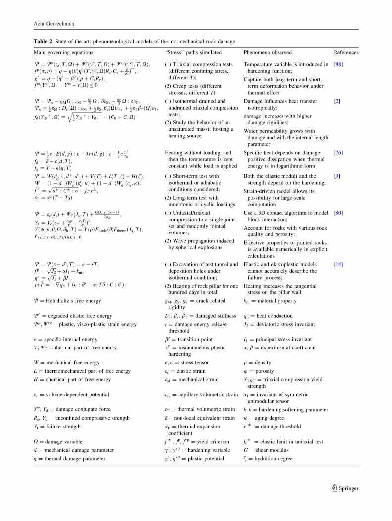
tensor). Table 2 summarizes the postulates made in
phenomenological thermo-mechanical damage models
proposed for rock. Most models are based on a purely
mechanical damage evolution law, which implies that
temperature can only affect damage if the tensile stress
induced by heating exceeds the threshold of mechanical
tensile strain necessary to open cracks. In practice, this
means that most models are based on the expression of a
damaged stiffness tensor, introduced in a thermo-elastic
stress/strain relationship.
3 A phenomenological model to predict the influence
of thermo-mechanical crack opening and closure
on rock stiffness
3.1 Outline of the modeling approach
The modeling approach adopted herein is illustrated in
Fig. 1. The free energy is sought in the form of a function
of state variables (in this thermo-mechanical study: defor-
mation e and temperature T) and internal (dissipation)
variables (in the present case: the damage tensor X). The
damage flow rule is assumed to be associate, which implies
that the damage potential is equal to the damage criterion.
The latter shall depend on damage and on the damage-
driving force that is work conjugate to damage. The
damage-driving force is sought in the form of a function of
both mechanical stress and temperature, in order to predict
crack propagation under thermo-mechanical stress gradi-
ents. Crack closure can be accounted for by introducing a
unilateral condition in the expression of the damaged
elastic stiffness used in the free energy [10]. Energy is
dissipated due to both mechanical and thermal effects;
therefore, the inequality of Clausius–Duhem (ICD) writes
as follows:
ðr : _e� _sS� _WSÞ þ � q
s� rs
� �� 0 ð3Þ
where WS and S are the free energy and the entropy of the
rock solid skeleton, respectively. q is the heat flow, and srepresents the variation of temperature compared to a given
reference state. Mechanical dissipation (first term of Eq. 3)
and thermal dissipation (second term of Eq. 3) are usually
considered both positive (stricto sensu, these two require-
ments are sufficient but not necessary to satisfy Eq. 3).
Constitutive equations (such as the stress/strain relationship)
are obtained by introducing the postulated expressions of the
free energy and the damage associate flow rule in the ICD.
3.2 Free energy of the damaged rock skeleton
The damage variable ðXÞ used in the proposed model is
defined as the second-order crack density tensor (Eq. 1),
Acta Geotechnica
123
Page 5
Table 2 State of the art: phenomenological models of thermo-mechanical rock damage
Main governing equations ‘‘Stress’’ paths simulated Phenomena observed References
W ¼ Weðee;T ;XÞ þWpðcp;T ;XÞ þWvpðcvp;T ;XÞ;f pðr; gÞ ¼ q� gðhÞgpðT ; cp;XÞRcðCs þ p
RcÞm;
gp ¼ q� ðgp � bpÞðpþ CsRcÞ;f xðYx;XÞ ¼ Yx � rðXÞ� 0
(1) Triaxial compression tests
(different confining stress,
different T);
(2) Creep tests (different
stresses, different T)
Temperature variable is introduced in
hardening function;
Capture both long-term and short-
term deformation behavior under
thermal effect
[88]
W ¼ We � gMX : eM � gs3X : deSv � gT
3X : deT;
We ¼ 12eM : DeðXÞ : eM þ 1
2eSvbsðXÞeSv þ 1
2eTbTðXÞeT;
fdðYd1þ;XÞ ¼
ffiffiffiffiffiffiffiffiffiffiffiffiffiffiffiffiffiffiffiffiffiffiffiffiffi12
Yd1þ : Yd1
þq
� ðC0 þ C1XÞ
(1) Isothermal drained and
undrained triaxial compression
tests;
(2) Study the behavior of an
unsaturated massif hosting a
heating source
Damage influences heat transfer
isotropically;
damage increases with higher
damage rigidities;
Water permeability grows with
damage and with the internal length
parameter
[2]
W ¼ 12e : Eðd; gÞ : e� Tnðd; gÞ : e� 1
2c T2
T0;
fd ¼ �e� kðd;TÞ;fg ¼ T � �kðg; TÞ
Heating without loading, and
then the temperature is kept
constant while load is applied
Specific heat depends on damage;
positive dissipation when thermal
energy is in logarithmic form
[76]
W ¼ Wðeie; j; d
þ; d�Þ þ VðTÞ þ LðT ; nÞ þ HðnÞ;W ¼ ð1� dþÞWþe ðei
e;jÞ þ ð1� d�ÞW�e ðeie;jÞ;
f� ¼ffiffiffiffiffiffiffiffiffiffiffiffiffiffiffiffiffiffiffiffiffiffiffi�r� : C� : �rp
� f�e r�;eT ¼ aTðT � T0Þ
(1) Short-term test with
isothermal or adiabatic
conditions considered;
(2) Long-term test with
monotonic or cyclic loadings
Both the elastic moduli and the
strength depend on the hardening;
Strain-drivien model allows its
possibility for large-scale
computation
[9]
W ¼ ecðJsÞ þWTðJs;TÞ þ GðJs;TÞða1�3Þ2qs0
;
Yf ¼ Ycðcm þ cnpYc� cnYf
3YcÞz;
Yð/; p; h;X; dh; TÞ ¼ Y ðpÞFLodeðhÞFthermðJs; TÞ;FðJs ;TÞ¼GðJs ;TÞ=GðJs ;T¼0Þ
(1) Uniaxial/triaxial
compression to a single joint
set and randomly jointed
volumes;
(2) Wave propagation induced
by spherical explosions
Use a 3D contact algorithm to model
block interaction;
Account for rocks with various rock
quality and porosity;
Effective properties of jointed rocks
is available numerically in explicit
calculations
[80]
W ¼ Wðe� ep;TÞ ¼ e� sT ;f p ¼
ffiffiffiffiffiJ2
pþ aI1 � km;
gp ¼ffiffiffiffiffiJ2
pþ bI1;
qc _T ¼ �rqh þ ðr : _ep � aTTd : C : _eeÞ
(1) Excavation of test tunnel and
deposition holes under
isothermal condition;
(2) Heating of rock pillar for one
hundred days in total
Elastic and elastoplastic models
cannot accurately describe the
failure process;
Heating increases the tangential
stress on the pillar wall
[14]
W ¼ Helmholtz’s free energy gM, gS, gT = crack-related
rigidity
km = material property
We ¼ degraded elastic free energy De, bs, bT = damaged stiffness qh = heat conduction
Wp;Wvp ¼ plastic, visco-plastic strain energy r = damage energy release
threshold
J2 = deviatoric stress invariant
e = specific internal energy bp = transition point I1 = principal stress invariant
V ;WT ¼ thermal part of free energy gp = instantaneous plastic
hardening
a, b = experimental coefficient
W = mechanical free energy �r;r ¼ stress tensor q = density
L = thermomechanical part of free energy ee = elastic strain / = porosity
H = chemical part of free energy eM = mechanical strain YTXC = triaxial compression yield
strength
ec = volume-dependent potential esv = capillary volumetric strain a1 = invariant of symmetric
unimodular tensor
Yx, Yd = damage conjugate force eT = thermal volumetric strain k; �k ¼ hardening-softening parameter
Rc, Yc = unconfined compressive strength �e ¼ non-local equivalent strain j = aging degree
Yf = failure strength aT = thermal expansion
coefficient
r ± = damage threshold
X ¼ damage variable f ± , fp, fvp = yield criterion fe± = elastic limit in uniaxial test
d = mechanical damage parameter cp, cvp = hardening variable G = shear modulus
g = thermal damage parameter gp, gvp = plastic potential n = hydration degree
Acta Geotechnica
123
Page 6
projected in its principal base. Assuming that rock has a
linear thermo-elastic behavior in the absence of damage,
the free energy of the rock solid skeleton ðWSÞ is sought in
the form of a polynomial of order two in deformation. The
polynomial is assumed to be linear in damage in order to
avoid the nonlinearities involved in having the energy
release rate (work conjugate to damage) depend on
damage:
WSðe; s;XÞ ¼1
2eE : DðXÞ : eE þ gX : e
� 1
2s0
CðXÞs2 � sKðXÞ : eE ð4Þ
In which DðXÞ is the damaged stiffness tensor. The term
gX : e represents the energy that needs to be released to
close residual cracks (i.e., cracks that remain open after
releasing a tensile loading). The two last terms of the free
energy ð� 12s0
CðXÞs2 � sKðXÞ: eEÞare the classical linear
thermo-elastic energy potentials. s0 is the initial
temperature, s is the temperature change, CðXÞ is the
damaged heat capacity. The coefficients of the diagonal
tensor KðXÞ are equal to the product of the damaged bulk
modulus kðXÞ by the thermal expansion coefficient of the
solid skeleton (aT). Note that the thermal expansion
coefficient aT is assumed to remain constant, while the
bulk modulus kðXÞ depends on damage. This is because in
the undamaged part of the bulk (i.e., outside the cracks),
solid thermal properties are unchanged. The mechanical
part of the proposed model is based on Halm and Dragon’s
model [28], which proved to perform well in predicting
brittle rock behavior. However, the model proposed herein
is different not only because thermo-mechanical couplings
are introduced, but also because total deformation (e) was
replaced by elastic deformation (eE) in the damaged elastic
potential (first part of Eq. 4). This substitution of
deformation variable has important implications on the
phenomenological definition of stress in the model, as will
be explained later in this subsection. The damaged elastic
deformation energy is written as follows:
1
2eE : DðXÞ : eE ¼ 1
2kðtreEÞ2 þ l trðeE � eEÞ
þ a treEtrðeE �XÞ þ 2b trðeE � eE �XÞð5Þ
The damage-induced irreversible strain eid is defined as
follows:
eid ¼ e� eE ð6Þ
In Eq. 5 above, k and l are Lame coefficients (for the
undamaged material). a, and b are damaged material
Table 2 continued
Main governing equations ‘‘Stress’’ paths simulated Phenomena observed References
p = mean stress c = specific heat capacity T = absolute temperature
q = deviatoric stress C = tangential modulus tensor T0 = reference temperature
h = Lode angle C0 = initial damage-stress rate s = entropy
m = curvature of yield surface C1 = damage increase rate Ftherm = thermal softening term
n = thermo-elastic coupling tensor C ± = tensile/compressive
metric tensor
Flode = Lode angle function
Kw = permeability cm, cn, z = material parameter eid = irreversible strain
d?, d- = damage indices Cs = coefficient of material
cohesion
Js = average dilatation of the solid
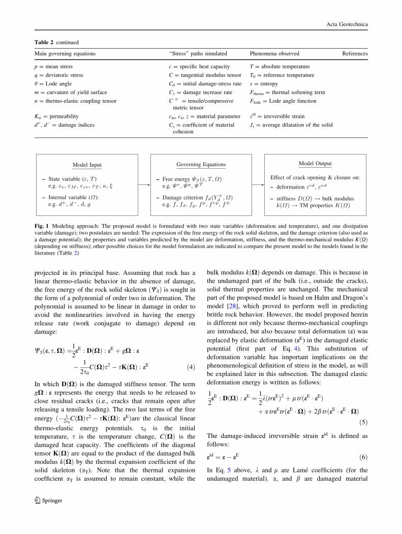
Fig. 1 Modeling approach: The proposed model is formulated with two state variables (deformation and temperature), and one dissipation
variable (damage); two postulates are needed: The expression of the free energy of the rock solid skeleton, and the damage criterion (also used as
a damage potential); the properties and variables predicted by the model are deformation, stiffness, and the thermo-mechanical modulus KðXÞ(depending on stiffness); other possible choices for the model formulation are indicated to compare the present model to the models found in the
literature (Table 2)
Acta Geotechnica
123
Page 7
parameters. For convenience, a condensed notation is
adopted:
WSðe; s;XÞ ¼1
2eE : DTðs;XÞ : eE � 1
2s0
CðXÞs2 þ gX : e
ð7Þ
In which DT is the damaged thermo-elastic tensor. The
proposed thermo-mechanical damage model is formulated
with a minimum number of postulated functionals. Irre-
versible strain eid is assumed to be entirely attributed to the
damage parameter X, and accordingly, only one ‘‘yield’’
criterion is introduced in the model. The damage evolution
law is obtained by applying a pseudo-associate flow rule
(more details on the definition of the damage-driving force
are provided in the next subsection). A rigorous thermody-
namic formulation would require deriving the evolution law
of eid from Legendre transformations of dissipation poten-
tials, as explained in [16]. In fact, a long-standing debate
exists in thermodynamics of irreversible processes regarding
the nature of the variables that shall be employed in energy
potentials. Introducing nonplastic, purely damage-induced
irreversible deformation raises thermodynamic consistency
issues, some of which are explained in [21, 36, 41, 46, 81], to
cite only a few references. Future theoretical work will be
undertaken by the authors and their collaborators to derive a
closed-form formulation from a single damage potential for
both damage and damage-induced irreversible deformation,
within a thermodynamically consistent framework.
The work presented in this paper focuses on constitutive
modeling and provides a unified framework to predict
damage in rock subjected to crack opening and closure
under thermo-mechanical stresses. For the sake of this
study, the proposed model is based on state-of-the-art
continuum damage mechanics. Stress is defined as the
work conjugate of total deformation. The thermodynamic
force conjugate to elastic strain eE is viewed as an equiv-
alent stress req, as defined in [2, 78]:
r ¼ req þ rR ¼ req þ gX ð8Þ
In which rR ¼ gX is the stress needed to close the cracks
that remain open after releasing a tensile loading. Fig. 2
explains the decompositions of stress and strain assumed in
the model, which lead to the following:
r ¼ DTðs;XÞ : e ¼ DTðs;XÞ : eE þ DTðs;XÞ : eid ð9Þ
Conveniently, the constitutive assumptions made allow
obtaining the evolution of irreversible strain as follows:
eid ¼ gDTðs;XÞ�1 : X ð10Þ
Conjugation relationships also provide the energy release
rate (also called damage-driving force), which is further
decomposed into two parts:
Y ¼ �oWSðe; s;XÞoX
¼ Y1 þ Y2 ð11aÞ
Y1 ¼ �ge� aðtreEÞeE � 2bðeE � eEÞ ð11bÞ
Y2 ¼1
2s0
oCðXÞoX
s2 þ soKðXÞ
oX: eE ð11cÞ
Stress evolution writes as follows:
dr ¼ DðXÞ : deE þ oDðXÞoX
: eE
� �: dXþ gdX
�KðXÞds� oKðXÞoX
dX
� �s
ð12Þ
The total deformation tensor is split into three components
[1], as shown in Fig. 2:
e ¼ eel þ eed þ eid ¼ eE þ eid ð13Þ
In which eel is the purely elastic deformation recoverable
by unloading in the absence of damage. eed is the additional
elastic deformation associated with the change of stiffness
due to damage. According to Fig. 2
eel ¼ D�1T0
: req ð14Þ
eed ¼ ½DTðXÞ�1 � D�1T0� : req ð15Þ
In which DT0is the undamaged thermo-elastic tensor. The
increment of elastic deformation is split into a mechanical
and a thermal component:
deE ¼ deEM þ deET ð16Þ
Within the proposed model formulation, crack-induced
deformation can be deduced from the evolution law of
damage [4], which is the only equation required at this
stage to close the model formulation. As explained in Sect.
3.1, the damage flow rule is assumed to be associate, which
means that the damage criterion is equal to the damage
potential.
3.3 Damage criterion
Only certain components of the thermodynamic variable
conjugate to damage (Y) are expected to contribute to
crack propagation, mainly mechanical and thermal tensile
stress maintaining cracks open after unloading. In addition,
rock strength is expected to decrease with a temperature
increase. The damage-driving force component Y1
(Eq. 11b) is decomposed into the following:
Y1 ¼ Y1a þ Y1b ð17aÞY1a ¼ �ge; ð17bÞ
Y1b ¼ �aðtreEÞeE � 2bðeE � eEÞ ð17cÞ
Yþ1a ¼ �geþ ð17dÞ
Acta Geotechnica
123
Page 8
Y�1a ¼ �gðe� eþÞ ð17eÞ
When cracks propagate in mode I (i.e., when cracks
open due to tension), Y1a? is the dominating damage-driving
force. Note that Y1a? accounts for tensile deformation
induced by mechanical stress or temperature increase
(Eq. 16). Y2 (Eq. 11c) accounts for the change of rock
properties due to temperature changes (Y2 = 0 in a purely
mechanical damage model). A quick dimensional analysis
indicates that the term 12s0
oCðXÞoX s2 can be neglected
(oCðXÞ
oX o KðXÞ½ �oX : eE). Note that inter-particle distance in
rock increases with temperature. At higher temperatures, it
requires more energy to separate rock crystals, which are
already more distant than at lower temperature. To capture
this reduction of crack toughness (resulting in a reduction
in rock strength) with temperature increase, and to
counteract the tensile damage-driving force Y1a? , the
following thermal damage-driving force is defined as
follows:
Yd2 ¼ A � s � aTðaþ 2bÞtrðeEþÞ ð18Þ
Where eEþ is the tensile elastic deformation, which
indicates the increase in inter-particle distance at high
temperature. A is a proportionality constant. Note that the
expression in Eq. 18 is proportional to aT(a ? 2b)s and
varies like a polynomial of order one in elastic
deformation, which is in agreement with the definition of
the bulk modulus, and with Eqs. 5 and 11c. As a result, the
total damage-driving force retained in the proposed
thermo-mechanical damage model (noted Yd?) is defined
as follows:
Yþd ¼ Yþ1a þ Yd2
¼� geþ þ A � s � aTðaþ 2bÞtrðeEþÞð19Þ
The damage criterion is expressed as the difference
between the norm of the energy release rate and an
energy threshold. The latter depends on damage (which
plays the role of a hardening variable), in order to capture
the increase of energy release rate with cumulated damage:
fdðYþd ;XÞ ¼ffiffiffiffiffiffiffiffiffiffiffiffiffiffiffiffiffiffiffi1
2Yþd : Yþd
r� ðC0 þ C1XÞ ð20Þ
in which C0 is the initial damage threshold which is
necessary to trigger damage, and C1 is a parameter which
controls crack growth with cumulated damage. The
increments of the Lagrange multiplier and of damage are
calculated by using the consistency conditions (i.e., fd = 0
and _fd ¼ 0):
dkd ¼ �ofdoYþ
d
: dYþdofdoX : ofd
oYþd
¼ Yþd : dYþdðC1dÞ : Yþd
ð21Þ
dX ¼ dkd
ofdðYþd ;XÞoYþd
¼
Yþdffiffiffiffiffiffiffiffiffiffiffi
2Yþd
:Yd
p þ
� �: dYþd
ðC1dÞ :Yþ
dffiffiffiffiffiffiffiffiffiffiffiffi2Yþ
d:Yþ
d
p� � Yþdffiffiffiffiffiffiffiffiffiffiffiffiffiffiffiffiffiffiffi
2Yþd : Yþdp" #
ð22Þ
3.4 Unilateral effects of crack closure on damaged
stiffness
The recovery of compression strength by the closure of
tensile cracks is known as unilateral condition in CDM. In
terms of stiffness, it can be expressed as [11]:
DeffðXÞ ¼ DðXÞ
þ gX3
i¼1
Hð�trðPi : eÞÞPi : ðD0 � DðXÞÞ : Pi
ð23Þ
In which DeffðXÞ is the ‘‘partially recovered’’ stiffness
tensor. Pi is the fourth-order projection tensor (projection
in crack planes normal to principal direction i). H is the
Heaviside function. g is a parameter that indicates the
degree of maximum stiffness recovery (0 \ g B 1). In the
following simulations, it is assumed that stiffness is fully
recovered as soon as cracks are closed under compression
(i.e., g = 1).
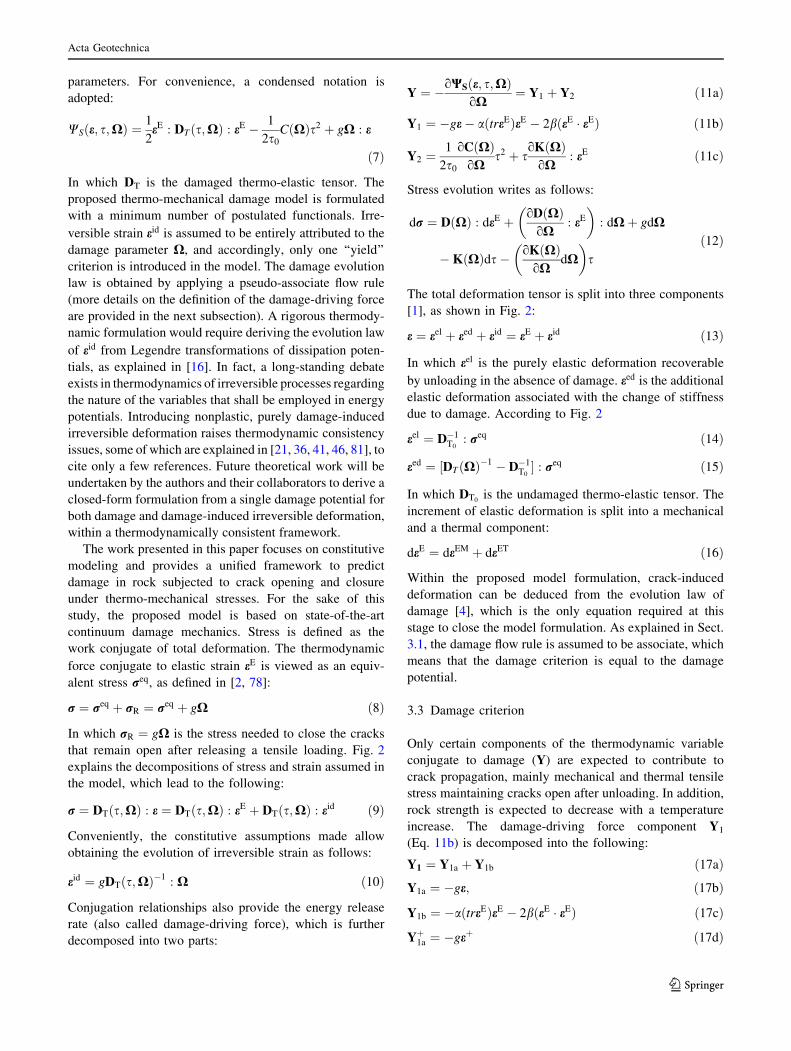
Fig. 2 Decomposition of total deformation (illustrated for a mechan-
ical stress path). In the proposed model, total deformation is the sum
of a purely elastic deformation ee (obtained in the absence of
damage), a damaged elastic deformation eed (additional elastic
deformation induced by the loss of rigidity in damaged states), and
an irreversible damage-induced deformation eid (due to residual crack
opening). req is the equivalent stress, work conjugate to total elastic
strains
Acta Geotechnica
123
Page 9
4 Parameter calibration, model verification
and sensitivity analysis
The advantage of the model proposed above is that the
number of parameters required is minimal (seven
mechanical parameters: k, l, a, b, g, C0, C1; and
one thermal parameter: aT). Published data sets on thermo-
mechanical behavior of both sandstone and granite are
available in the literature [34, 55, 79, 84]. However, most
of the data are analyzed within the framework of thermo-
elasticity, and there is not enough evidence on stiffness
weakening and irreversible deformation induced by tem-
perature gradients to really verify the proposed model
against experimental data. According to experimental
studies published in [28, 29] the proposed thermo-
mechanical damage model is expected to provide good
predictions of tight rock macroscopic failure induced by
crack opening and closure. Many authors used a similar
mechanical damage model for sandstone, even though
other mechanisms such as grain crushing and pore collapse
are expected to drive macroscopic failure in porous rock.
The proposed model is seen as a versatile framework that
can be used to capture the loss of energy induced by
damage in any rock material, provided that model param-
eters are well calibrated. In order to assess the performance
of the model in doing so, calibration and verification
simulations were performed on sandstone, for which
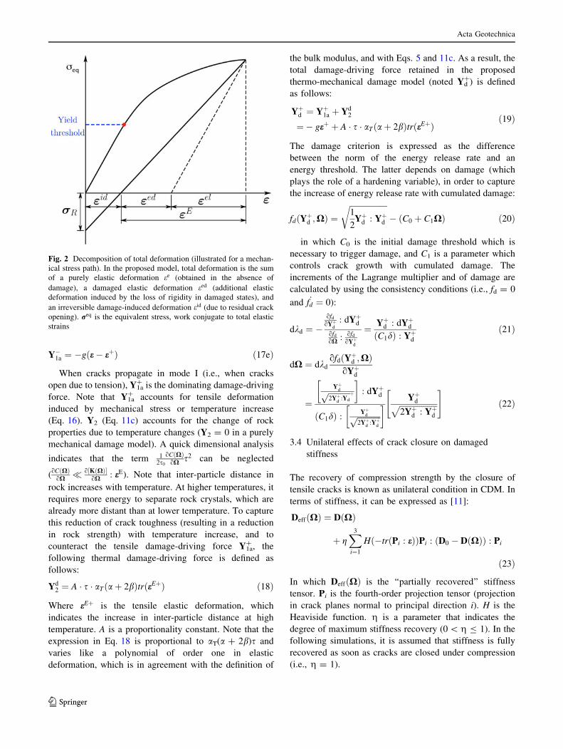
experimental data were found in [77] (drained triaxial
compression tests on saturated sandstone). Reference
stress/strain curves for this calibration were obtained for a
confining pressure of 40 MPa. The triaxial tests used for
model verification purposes were performed for confining
pressures amounting to 28 MPa and 50 MPa. The corre-
sponding stress/strain curves are displayed in Fig. 3. Note
that the soil mechanics sign convention was adopted
throughout the paper (with compression counted positive).
The plots obtained for the verification tests (at 28 and
50 MPa) show that the model predictions match experi-
mental data with an error less than 5 % before the peak of
stress. This is considered as a satisfactory result, since the
purpose of this study is to predict the effect of thermo-
mechanical crack opening and closure before softening.
Due to the thermo-elastic framework adopted in the pro-
posed model (Eq. 4), the expression of the damaged
thermo-mechanical stiffness KðXÞ results from the
expression of the damaged stiffness tensor, so that the
thermal expansion coefficient aT can be considered as a
purely thermo-elastic parameter—not a damage parameter.
That is the reason why in the present study, aT was
assigned a value known to be a standard for rock materials
(negative with the soil mechanics sign convention).
Table 3 summarizes the parameters obtained for sandstone
after calibration and verification—referred to as the
parameters of ‘‘Type I sandstone’’ in the following.
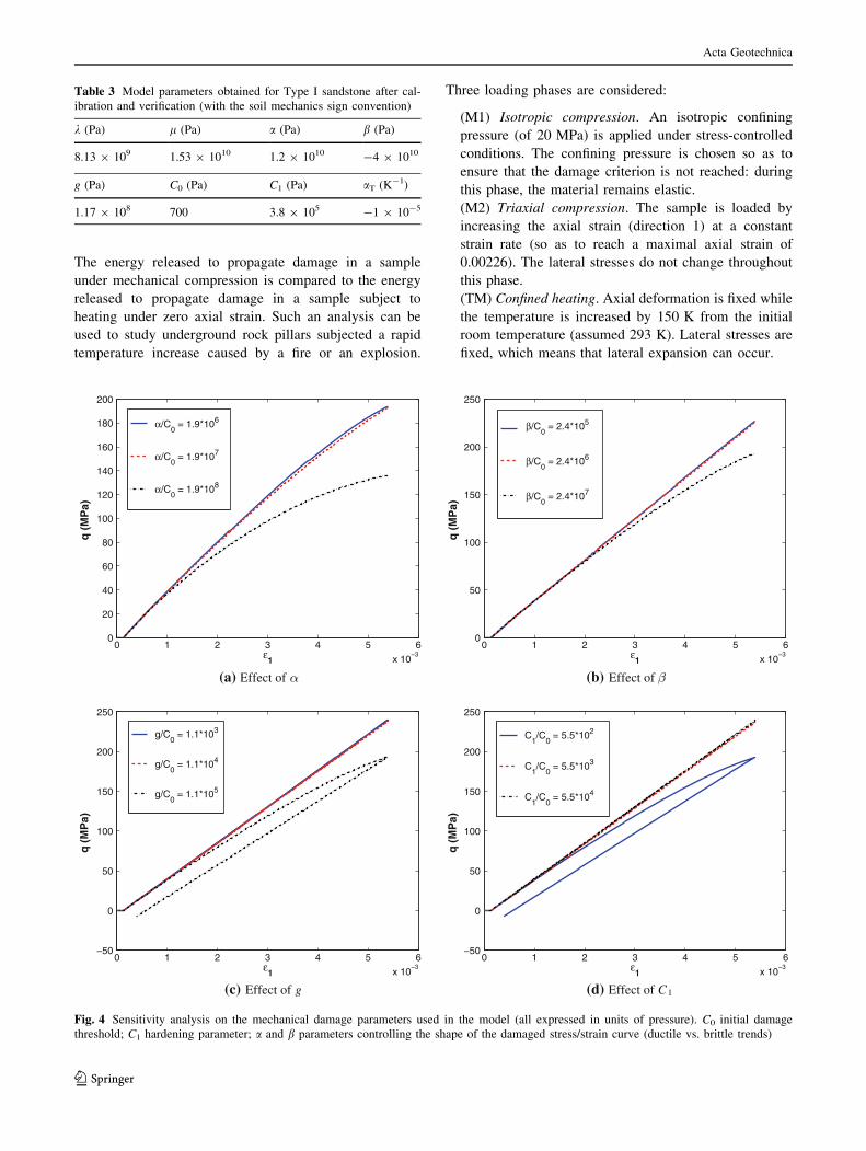
A sensitivity analysis is now carried out in order to
explain the physical meaning of the five mechanical
damage parameters (a, b, g, C0, C1). Strain-controlled
triaxial compression tests were simulated (for a confining
pressure of 15 MPa). The initial damage threshold C0 was
used as a scaling factor. The values of the normalized
damage parameters (a/C0, b/C0, g/C0, C1/C0) were
first assigned a value according to the calibration study
published in [28] for sandstone (for reference, the set of
constitutive parameter is reported in Table 4). Each nor-
malized parameter was then varied one by one, keeping all
the other parameters constant (Fig. 4). Larger a and bvalues imply a more ductile behavior, as can be seen from
the portion of the stress–strain curve corresponding to
higher deformation (Fig. 4a, b). As g increases, the irre-
versible deformation and corresponding residual stress
increase. So the peak of the stress–strain curve tends to
shift downward (Fig. 4c). C1 has an influence on the strain-
hardening portion as damage starts to accumulate (Fig. 4d).
5 Analysis of thermo-mechanical stress paths
5.1 Simulation of thermo-mechanical crack opening
The thermo-mechanical damage model presented in Sect. 3
was used to simulate crack-induced damage during a tri-
axial compression test comprising a thermo-mechanical
loading phase, for the Type I sandstone studied in Sect. 4.
−6 −4 −2 0 2 4 6 8 10 12x 10
−3
0
50
100
150
200
250
300
ε3
q (M
Pa)
50 MPa (v)
40 MPa (c)
28 MPa (v)
50 MPa (v)
40 MPa (c)
28 MPa (v)
ε1
Fig. 3 Stress/strain curves obtained during drained triaxial compres-
sion tests conducted on saturated sandstone: the dots are reported
experimental data found in [77]; solid and dashed lines represent the
results of simulations performed in MATLAB with the proposed
damage model. The curve used for model calibration (c) corresponds
to the test performed under a confining pressure of 40 MPa.
Simulations for model verification (v) were performed for confining
pressures of 28 and 50 MPa
Acta Geotechnica
123
Page 10
The energy released to propagate damage in a sample
under mechanical compression is compared to the energy
released to propagate damage in a sample subject to
heating under zero axial strain. Such an analysis can be
used to study underground rock pillars subjected a rapid
temperature increase caused by a fire or an explosion.
Three loading phases are considered:
(M1) Isotropic compression. An isotropic confining
pressure (of 20 MPa) is applied under stress-controlled
conditions. The confining pressure is chosen so as to
ensure that the damage criterion is not reached: during
this phase, the material remains elastic.
(M2) Triaxial compression. The sample is loaded by
increasing the axial strain (direction 1) at a constant
strain rate (so as to reach a maximal axial strain of
0.00226). The lateral stresses do not change throughout
this phase.
(TM) Confined heating. Axial deformation is fixed while
the temperature is increased by 150 K from the initial
room temperature (assumed 293 K). Lateral stresses are
fixed, which means that lateral expansion can occur.
Table 3 Model parameters obtained for Type I sandstone after cal-
ibration and verification (with the soil mechanics sign convention)
k (Pa) l (Pa) a (Pa) b (Pa)
8.13 9 109 1.53 9 1010 1.2 9 1010 -4 9 1010
g (Pa) C0 (Pa) C1 (Pa) aT (K-1)
1.17 9 108 700 3.8 9 105 -1 9 10-5
0 1 2 3 4 5 6
x 10−3
0
20
40
60
80
100
120
140
160
180
200
ε1
q (
MP
a)
α/C0 = 1.9*106
α/C0 = 1.9*107
α/C0 = 1.9*108
0 1 2 3 4 5 6
x 10−3
0
50
100
150
200
250
ε1
q (
MP
a)
β/C0 = 2.4*105
β/C0 = 2.4*106
β/C0 = 2.4*107
0 1 2 3 4 5 6
x 10−3
−50
0
50
100
150
200
250
ε1
q (
MP
a)
g/C0 = 1.1*103
g/C0 = 1.1*104
g/C0 = 1.1*105
0 1 2 3 4 5 6
x 10−3
−50
0
50
100
150
200
250
ε1
q (
MP
a)
C1/C
0 = 5.5*102
C1/C
0 = 5.5*103
C1/C
0 = 5.5*104
g
(a) Effect of (b)
Effect of (d) Effect of C1
Fig. 4 Sensitivity analysis on the mechanical damage parameters used in the model (all expressed in units of pressure). C0 initial damage
threshold; C1 hardening parameter; a and b parameters controlling the shape of the damaged stress/strain curve (ductile vs. brittle trends)
Acta Geotechnica
123
Page 11
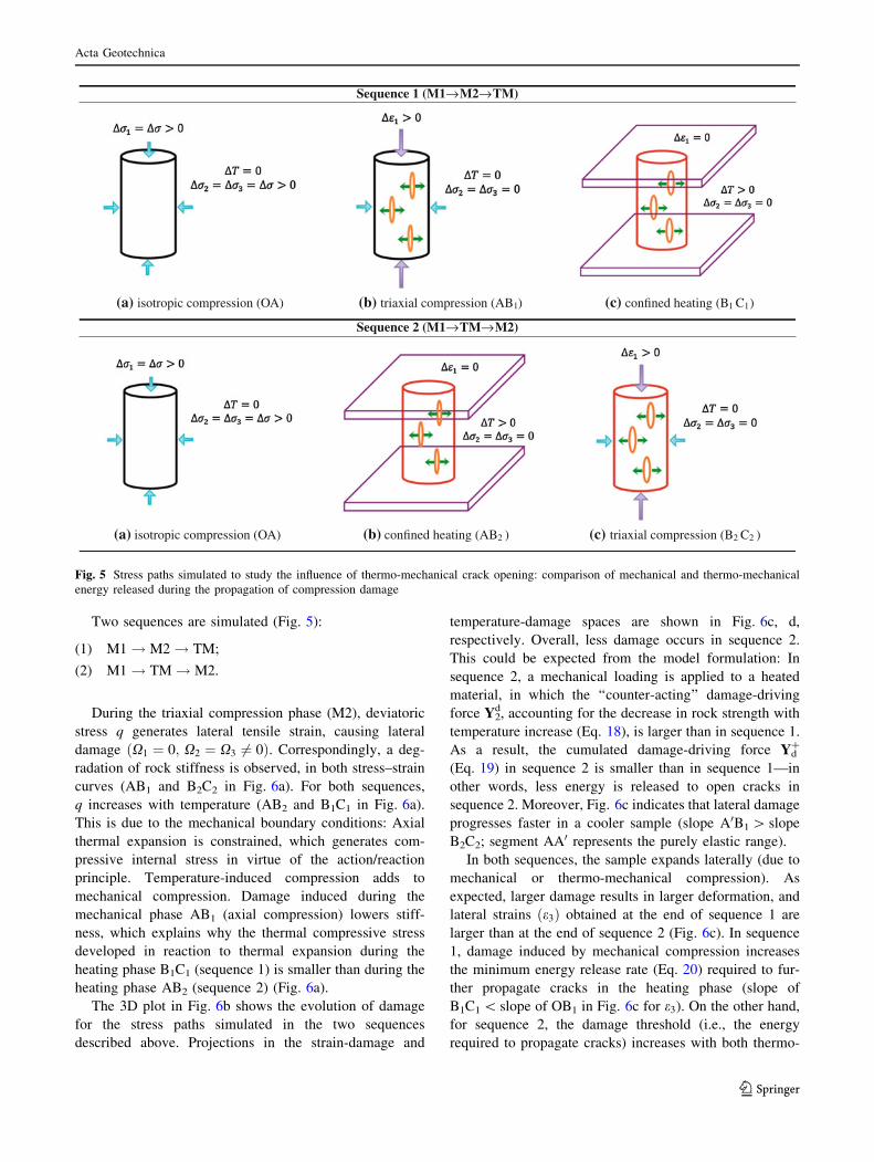
Two sequences are simulated (Fig. 5):
(1) M1! M2! TM;
(2) M1! TM! M2.
During the triaxial compression phase (M2), deviatoric
stress q generates lateral tensile strain, causing lateral
damage ðX1 ¼ 0; X2 ¼ X3 6¼ 0Þ. Correspondingly, a deg-
radation of rock stiffness is observed, in both stress–strain
curves (AB1 and B2C2 in Fig. 6a). For both sequences,
q increases with temperature (AB2 and B1C1 in Fig. 6a).
This is due to the mechanical boundary conditions: Axial
thermal expansion is constrained, which generates com-
pressive internal stress in virtue of the action/reaction
principle. Temperature-induced compression adds to
mechanical compression. Damage induced during the
mechanical phase AB1 (axial compression) lowers stiff-
ness, which explains why the thermal compressive stress
developed in reaction to thermal expansion during the
heating phase B1C1 (sequence 1) is smaller than during the
heating phase AB2 (sequence 2) (Fig. 6a).
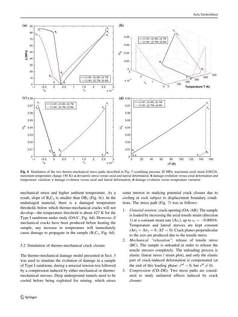
The 3D plot in Fig. 6b shows the evolution of damage
for the stress paths simulated in the two sequences
described above. Projections in the strain-damage and
temperature-damage spaces are shown in Fig. 6c, d,
respectively. Overall, less damage occurs in sequence 2.
This could be expected from the model formulation: In
sequence 2, a mechanical loading is applied to a heated
material, in which the ‘‘counter-acting’’ damage-driving
force Y2d, accounting for the decrease in rock strength with
temperature increase (Eq. 18), is larger than in sequence 1.
As a result, the cumulated damage-driving force Yd?
(Eq. 19) in sequence 2 is smaller than in sequence 1—in
other words, less energy is released to open cracks in
sequence 2. Moreover, Fig. 6c indicates that lateral damage
progresses faster in a cooler sample (slope A0B1 [ slope
B2C2; segment AA0 represents the purely elastic range).
In both sequences, the sample expands laterally (due to
mechanical or thermo-mechanical compression). As
expected, larger damage results in larger deformation, and
lateral strains ðe3Þ obtained at the end of sequence 1 are
larger than at the end of sequence 2 (Fig. 6c). In sequence
1, damage induced by mechanical compression increases
the minimum energy release rate (Eq. 20) required to fur-
ther propagate cracks in the heating phase (slope of
B1C1 \ slope of OB1 in Fig. 6c for e3). On the other hand,
for sequence 2, the damage threshold (i.e., the energy
required to propagate cracks) increases with both thermo-
Sequence 1 (M1→M2→TM)
(a) isotropic compression (OA) (b) triaxial compression (AB1) (c) confined heating (B1 C1)
Sequence 2 (M1→TM→M2)
2(a) isotropic compression (OA) (b) confined heating (AB ) (c) triaxial compression (B2 C2 )
Fig. 5 Stress paths simulated to study the influence of thermo-mechanical crack opening: comparison of mechanical and thermo-mechanical
energy released during the propagation of compression damage
Acta Geotechnica
123
Page 12
mechanical stress and higher ambient temperature. As a
result, slope of B2C2 is smaller than OB2 (Fig. 6c). In the
undamaged material, there is a damaged temperature
threshold, below which thermo-mechanical cracks will not
develop—the temperature threshold is about 427 K for the
Type I sandstone under study (OAA’, Fig. 6d). However, if
mechanical cracks have been produced before heating the
sample, any increase in temperature will immediately
cause damage to propagate in the sample (B1C1, Fig. 6d).
5.2 Simulation of thermo-mechanical crack closure
The thermo-mechanical damage model presented in Sect. 3
was used to simulate the evolution of damage in a sample
of Type I sandstone, during a uniaxial tension test followed
by a compression induced by either mechanical or thermo-
mechanical stresses. Deep underground tunnels need to be
cooled before being exploited for mining, which raises
some interest in studying potential crack closure due to
cooling in rock subject to displacement boundary condi-
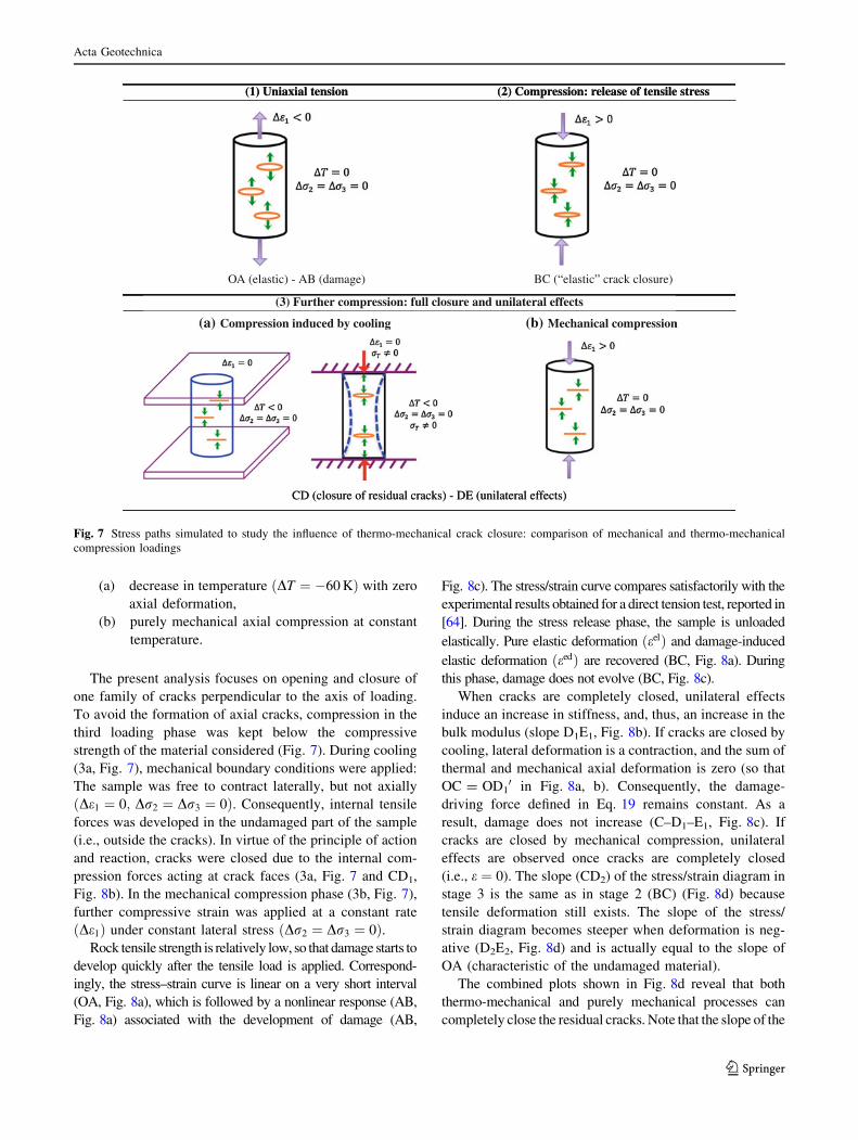
tions. The stress path (Fig. 7) was as follows:
1. Uniaxial tension: crack opening (OA–AB). The sample
is loaded by increasing the axial tensile strain (direction
1) at a constant strain rate (De1), up to e1 ¼ �0:00016.
Temperature and lateral stresses are kept constant
(Dr2 ¼ Dr3 ¼ 0; DT ¼ 0). Crack planes perpendicular
to the axis are produced due to the tensile stress.
2. Mechanical ‘‘relaxation’’: release of tensile stress
(BC). The sample is unloaded in order to release the
tensile stresses completely. The unloading process is
elastic (linear stress / strain plot), and only the elastic
part of crack-induced deformation is compensated (at
the end of this loading phase: eed ¼ 0, but eid 6¼ 0).
3. Compression (CD–DE). Two stress paths are consid-
ered to study unilateral effects induced by crack
closure:
−1 −0.5 0 0.5 1 1.5 2 2.5 3x 10
−3
0
10
20
30
40
50
60
70
80
90
ε3
q (
MP
a)
(1) M1; (2) M2; (3) TM(1) M1; (2) TM; (3) M2
O
C1
C2
B2
A
B1
C1
C2
B1
B2
ε1
0100
200300
400500
0
1
2
3
x 10−3
0
0.02
0.04
0.06
0.08
Temperature T (K)
ε1
Ω3
(1) M1; (2) M2; (3) TM(1) M1; (2) TM; (3) M2
OA
B1
C1
C2
B2
−1 −0.5 0 0.5 1 1.5 2 2.5 3x 10
−3
0
0.01
0.02
0.03
0.04
0.05
0.06
0.07
0.08
ε1
Ω3
(1) M1; (2) M2; (3) TM(1) M1; (2) TM; (3) M2 C
2
C1
B2
C2
O
C1
B1
A A’
ε3
B1
B2
0 20 40 60 80 100 120 140 1600
0.01
0.02
0.03
0.04
0.05
0.06
0.07
0.08
ΔT (K)
Ω3
(1) M1; (2) M2; (3) TM(1) M1; (2) TM; (3) M2
O, A
B1
C2
C1
B2
A’
(a) (b)
(c) (d)
Fig. 6 Simulation of the two thermo-mechanical stress paths described in Fig. 5 (confining pressure 20 MPa; maximum axial strain 0.00226;
maximum temperature change 150 K): a deviatoric stress versus axial and lateral deformation; b damage evolution versus axial deformation and
temperature variation; c damage evolution versus axial and lateral deformation; d damage evolution versus temperature variation
Acta Geotechnica
123
Page 13
(a) decrease in temperature ðDT ¼ �60 KÞ with zero
axial deformation,
(b) purely mechanical axial compression at constant
temperature.
The present analysis focuses on opening and closure of
one family of cracks perpendicular to the axis of loading.
To avoid the formation of axial cracks, compression in the
third loading phase was kept below the compressive
strength of the material considered (Fig. 7). During cooling
(3a, Fig. 7), mechanical boundary conditions were applied:
The sample was free to contract laterally, but not axially
ðDe1 ¼ 0; Dr2 ¼ Dr3 ¼ 0Þ. Consequently, internal tensile
forces was developed in the undamaged part of the sample
(i.e., outside the cracks). In virtue of the principle of action
and reaction, cracks were closed due to the internal com-
pression forces acting at crack faces (3a, Fig. 7 and CD1,
Fig. 8b). In the mechanical compression phase (3b, Fig. 7),
further compressive strain was applied at a constant rate
ðDe1Þ under constant lateral stress ðDr2 ¼ Dr3 ¼ 0Þ.Rock tensile strength is relatively low, so that damage starts to
develop quickly after the tensile load is applied. Correspond-
ingly, the stress–strain curve is linear on a very short interval
(OA, Fig. 8a), which is followed by a nonlinear response (AB,
Fig. 8a) associated with the development of damage (AB,
Fig. 8c). The stress/strain curve compares satisfactorily with the
experimental results obtained for a direct tension test, reported in
[64]. During the stress release phase, the sample is unloaded
elastically. Pure elastic deformation ðeelÞ and damage-induced
elastic deformation ðeedÞ are recovered (BC, Fig. 8a). During
this phase, damage does not evolve (BC, Fig. 8c).
When cracks are completely closed, unilateral effects
induce an increase in stiffness, and, thus, an increase in the
bulk modulus (slope D1E1, Fig. 8b). If cracks are closed by
cooling, lateral deformation is a contraction, and the sum of
thermal and mechanical axial deformation is zero (so that
OC = OD10 in Fig. 8a, b). Consequently, the damage-
driving force defined in Eq. 19 remains constant. As a
result, damage does not increase (C–D1–E1, Fig. 8c). If
cracks are closed by mechanical compression, unilateral
effects are observed once cracks are completely closed
(i.e., e ¼ 0). The slope (CD2) of the stress/strain diagram in
stage 3 is the same as in stage 2 (BC) (Fig. 8d) because
tensile deformation still exists. The slope of the stress/
strain diagram becomes steeper when deformation is neg-
ative (D2E2, Fig. 8d) and is actually equal to the slope of
OA (characteristic of the undamaged material).
The combined plots shown in Fig. 8d reveal that both
thermo-mechanical and purely mechanical processes can
completely close the residual cracks. Note that the slope of the
ssertselisnetfoesaeler:noisserpmoC)2(noisnetlaixainU)1(
)erusolckcarc”citsale“(CB)egamad(BA-)citsale(AO
(3) Further compression: full closure and unilateral effects
noisserpmoclacinahceMgniloocybdecudninoisserpmoC
CD (closure of residual cracks) - DE (unilateral effects)
ssertselisnetfoesaeler:noisserpmoC)2(noisnetlaixainU)1(
)erusolckcarc”citsale“(CB)egamad(BA-)citsale(AO
(3) Further compression: full closure and unilateral effects
noisserpmoclacinahceM(b)gniloocybdecudninoisserpmoC(a)
CD (closure of residual cracks) - DE (unilateral effects)
Fig. 7 Stress paths simulated to study the influence of thermo-mechanical crack closure: comparison of mechanical and thermo-mechanical
compression loadings
Acta Geotechnica
123
Page 14
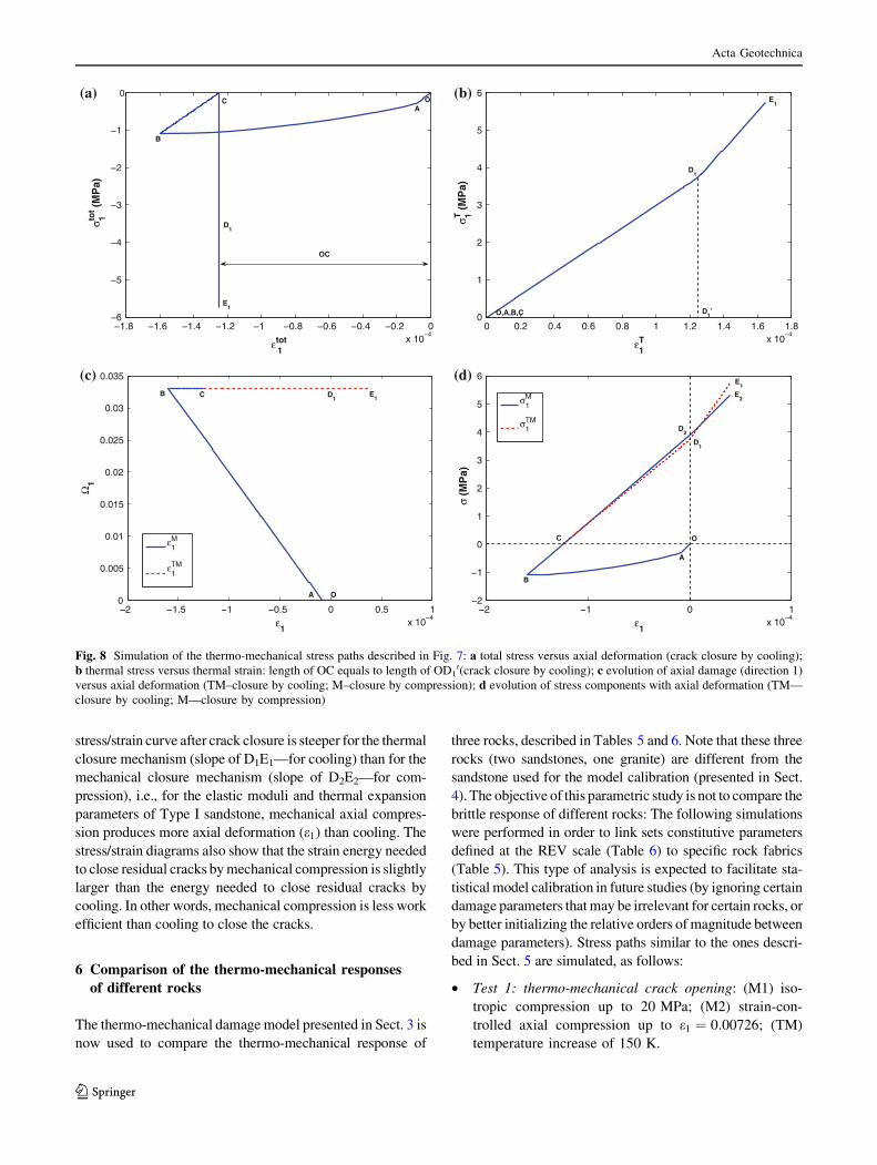
stress/strain curve after crack closure is steeper for the thermal
closure mechanism (slope of D1E1—for cooling) than for the
mechanical closure mechanism (slope of D2E2—for com-
pression), i.e., for the elastic moduli and thermal expansion
parameters of Type I sandstone, mechanical axial compres-
sion produces more axial deformation (e1) than cooling. The
stress/strain diagrams also show that the strain energy needed
to close residual cracks by mechanical compression is slightly
larger than the energy needed to close residual cracks by
cooling. In other words, mechanical compression is less work
efficient than cooling to close the cracks.
6 Comparison of the thermo-mechanical responses
of different rocks
The thermo-mechanical damage model presented in Sect. 3 is
now used to compare the thermo-mechanical response of
three rocks, described in Tables 5 and 6. Note that these three
rocks (two sandstones, one granite) are different from the
sandstone used for the model calibration (presented in Sect.
4). The objective of this parametric study is not to compare the
brittle response of different rocks: The following simulations
were performed in order to link sets constitutive parameters
defined at the REV scale (Table 6) to specific rock fabrics
(Table 5). This type of analysis is expected to facilitate sta-
tistical model calibration in future studies (by ignoring certain
damage parameters that may be irrelevant for certain rocks, or
by better initializing the relative orders of magnitude between
damage parameters). Stress paths similar to the ones descri-
bed in Sect. 5 are simulated, as follows:
• Test 1: thermo-mechanical crack opening: (M1) iso-
tropic compression up to 20 MPa; (M2) strain-con-
trolled axial compression up to e1 ¼ 0:00726; (TM)
temperature increase of 150 K.
−1.8 −1.6 −1.4 −1.2 −1 −0.8 −0.6 −0.4 −0.2 0x 10
−4
−6
−5
−4
−3
−2
−1
0
ε1tot
σ 1tot (
MP
a)O
B
C
E1
A
D1
OC
0 0.2 0.4 0.6 0.8 1 1.2 1.4 1.6 1.8x 10
−4
0
1
2
3
4
5
6
ε1T
σ 1T (
MP
a)
O,A,B,C
E1
D1
D1’
−2 −1.5 −1 −0.5 0 0.5 1x 10
−4
0
0.005
0.01
0.015
0.02
0.025
0.03
0.035
ε1
Ω1
ε1M
ε1TM
OA
C D1
E1
B
−2 −1 0 1x 10
−4
−2
−1
0
1
2
3
4
5
6
ε1
σ (M
Pa)
σ1M
σ1TM
O
A
B
C
D1
D2
E2
E1
(a) (b)
(c) (d)
Fig. 8 Simulation of the thermo-mechanical stress paths described in Fig. 7: a total stress versus axial deformation (crack closure by cooling);
b thermal stress versus thermal strain: length of OC equals to length of OD10(crack closure by cooling); c evolution of axial damage (direction 1)
versus axial deformation (TM–closure by cooling; M–closure by compression); d evolution of stress components with axial deformation (TM—
closure by cooling; M—closure by compression)
Acta Geotechnica
123
Page 15
• Test 2: thermo-mechanical crack opening: (M1) iso-
tropic compression up to 20 MPa; (TM) temperature
increase of 150 K; (M2) strain-controlled axial com-
pression up to e1 ¼ 0:00726.
• Test 3: thermo-mechanical crack opening: (M1) iso-
tropic compression up to 20 MPa; (TM) temperature
increase of 450 K; (M2) strain-controlled axial com-
pression up to e1 ¼ 0:00726.
• Test 4: thermo-mechanical crack closure: (1) strain-
controlled uniaxial tension up to e1 ¼ �0:00015; (2)
relaxation of axial tensile stress; (3) decrease in temper-
ature (DT ¼ �60 K) with zero axial deformation.
• Test 5: thermo-mechanical crack closure: (1) strain-
controlled uniaxial tension up to e1 ¼ �0:00015; (2)
relaxation of axial tensile stress; (3) purely mechanical
axial compression at constant temperature.
As mentioned earlier, the theoretical model presented in
Sect. 3 depends on seven mechanical parameters (k, l,
a, b, g, C0, C1) and one thermal parameter (aT). The
simulations presented below were performed with a stan-
dard value for the thermal expansion coefficient (aT),
which, according to the model formulation, does not
depend on damage. The values of the mechanical param-
eters were calibrated against experimental data elsewhere
[23, 29, 70] and used as such in the following parametric
study (Table 6). Note that the calibration process used by
the authors cited in Table 6 is not straightforward. In fact,
any data point provided by the experimental stress/strain
curve adds not only one equation, but also one unknown
(the value of current damage at that point). As a result, an
iterative calibration technique was proposed by Halm and
Dragon [23]. The elastic constants k and l are determined
from the initial Young’s modulus E0 and initial Poisson’s
ratio m0 in the elastic region (fd \ 0) of the stress/strain
curve. The subsequent nonelastic loading and elastic
unloading portions are then used to get the values of
aX3; bX3, and gX3 (where X3 stands for the lateral damage
developing during a triaxial compression test). The axial
deformation measured when damage first occurs provides
the initial damage threshold. Another point of the stress/
strain curve can be used at the beginning of the unloading
phase, in order to relate the parameters C0 and C1 to
g. Iterations are required to identify the most appropriate
value for X3. By this means, the set of material parameters
can be determined from a single loading–unloading triaxial
compression stress path.
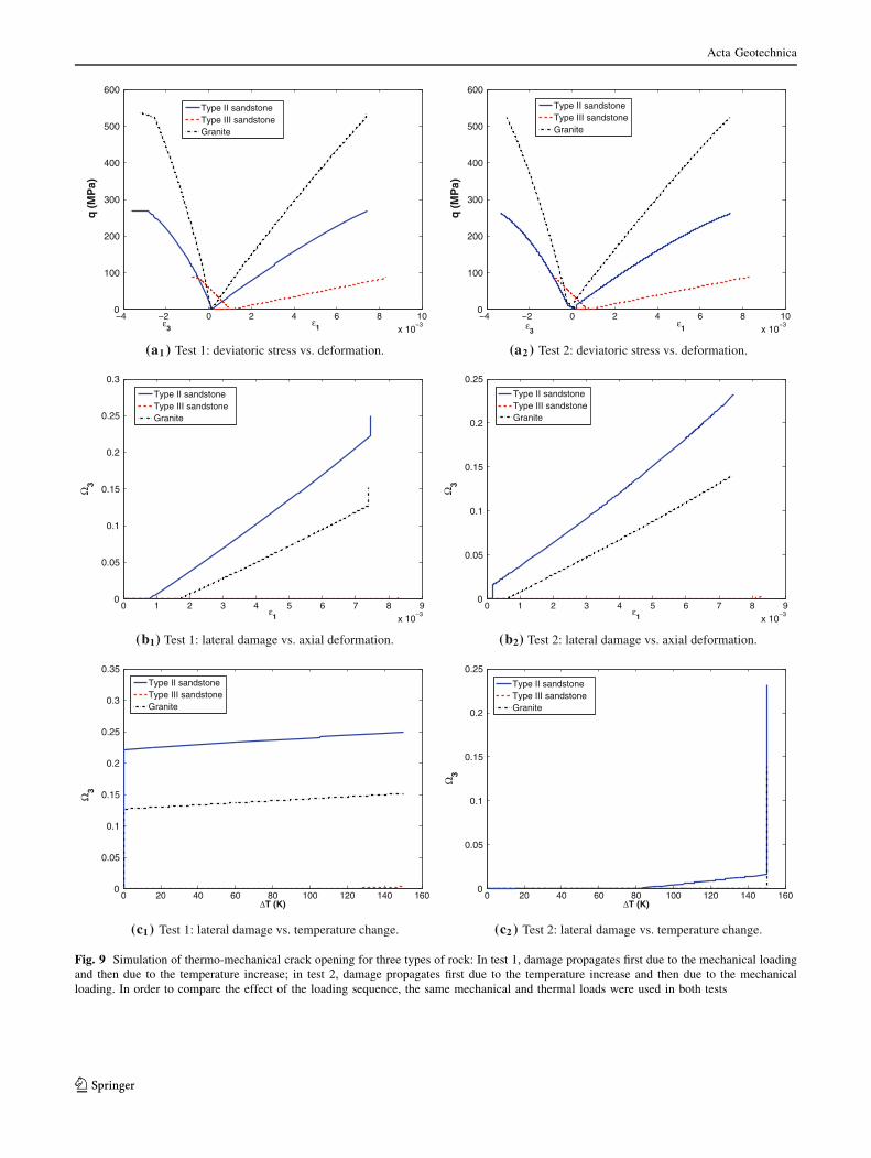
Results obtained for the three types of rock during tests
1 and 2 (resp. test 3) are displayed in Fig. 9 (resp. Fig. 10).
In tests 1 and 2, the sample expands laterally (due to
mechanical or thermo-mechanical compression). As noted
earlier in Sect. 5.1, the energy that needs to be released to
open cracks during the heating phase is larger in test 1 than
in test 2, because of damage hardening. As a result, thermal
damage is observed for a lower temperature increase in test
2 (Fig. 9c1, c2). Like in the test performed on Type I
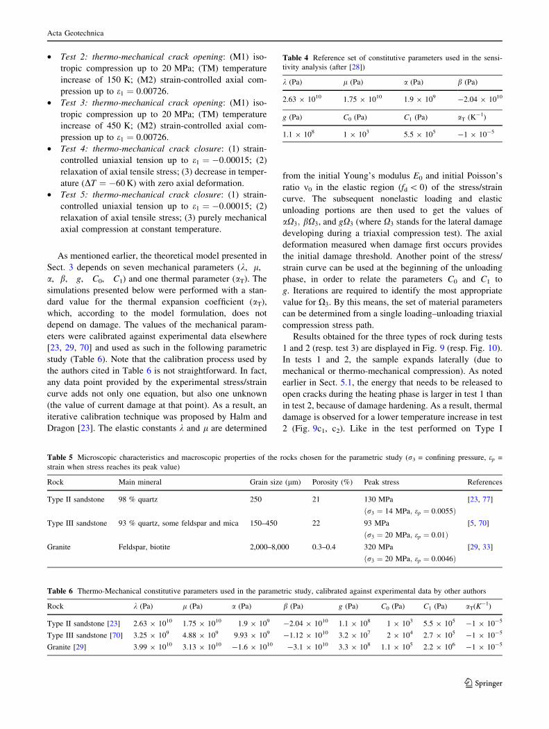
Table 4 Reference set of constitutive parameters used in the sensi-
tivity analysis (after [28])
k (Pa) l (Pa) a (Pa) b (Pa)
2.63 9 1010 1.75 9 1010 1.9 9 109 -2.04 9 1010
g (Pa) C0 (Pa) C1 (Pa) aT (K-1)
1.1 9 108 1 9 103 5.5 9 105 -1 9 10-5
Table 5 Microscopic characteristics and macroscopic properties of the rocks chosen for the parametric study (r3 = confining pressure, ep =
strain when stress reaches its peak value)
Rock Main mineral Grain size (lm) Porosity (%) Peak stress References
Type II sandstone 98 % quartz 250 21 130 MPa
ðr3 ¼ 14 MPa; ep ¼ 0:0055Þ[23, 77]
Type III sandstone 93 % quartz, some feldspar and mica 150–450 22 93 MPa
ðr3 ¼ 20 MPa; ep ¼ 0:01Þ[5, 70]
Granite Feldspar, biotite 2,000–8,000 0.3–0.4 320 MPa
ðr3 ¼ 20 MPa; ep ¼ 0:0046Þ[29, 33]
Table 6 Thermo-Mechanical constitutive parameters used in the parametric study, calibrated against experimental data by other authors
Rock k (Pa) l (Pa) a (Pa) b (Pa) g (Pa) C0 (Pa) C1 (Pa) aT(K-1)
Type II sandstone [23] 2.63 9 1010 1.75 9 1010 1.9 9 109 -2.04 9 1010 1.1 9 108 1 9 103 5.5 9 105 -1 9 10-5
Type III sandstone [70] 3.25 9 109 4.88 9 109 9.93 9 109 -1.12 9 1010 3.2 9 107 2 9 104 2.7 9 105 -1 9 10-5
Granite [29] 3.99 9 1010 3.13 9 1010 -1.6 9 1010 -3.1 9 1010 3.3 9 108 1.1 9 105 2.2 9 106 -1 9 10-5
Acta Geotechnica
123
Page 16
−4 −2 0 2 4 6 8 10
x 10−3
0
100
200
300
400
500
600
ε1
q (
MP
a)
Type II sandstoneType III sandstoneGranite
ε3
−4 −2 0 2 4 6 8 10
x 10−3
0
100
200
300
400
500
600
ε1
q (
MP
a)
Type II sandstoneType III sandstoneGranite
ε3
(a1 ) Test 1: deviatoric stress vs. deformation. (a2 ) Test 2: deviatoric stress vs. deformation.
0 1 2 3 4 5 6 7 8 9
x 10−3
0
0.05
0.1
0.15
0.2
0.25
0.3
ε1
Ω3
Type II sandstoneType III sandstoneGranite
0 1 2 3 4 5 6 7 8 9
x 10−3
0
0.05
0.1
0.15
0.2
0.25
ε1
Ω3
Type II sandstoneType III sandstoneGranite
(b1) Test 1: lateral damage vs. axial deformation. (b2) Test 2: lateral damage vs. axial deformation.
0 20 40 60 80 100 120 140 1600
0.05
0.1
0.15
0.2
0.25
0.3
0.35
ΔT (K)
Ω3
Type II sandstoneType III sandstoneGranite
0 20 40 60 80 100 120 140 1600
0.05
0.1
0.15
0.2
0.25
ΔT (K)
Ω3
Type II sandstoneType III sandstoneGranite
(c1) Test 1: lateral damage vs. temperature change. (c2 ) Test 2: lateral damage vs. temperature change.
Fig. 9 Simulation of thermo-mechanical crack opening for three types of rock: In test 1, damage propagates first due to the mechanical loading
and then due to the temperature increase; in test 2, damage propagates first due to the temperature increase and then due to the mechanical
loading. In order to compare the effect of the loading sequence, the same mechanical and thermal loads were used in both tests
Acta Geotechnica
123
Page 17
sandstone (Sect. 5.1), the total amount of damage produced
in test 1 exceeds the total amount of damage obtained in
test 2 (Fig. 9b1, b2). In this particular parametric study,
Type III sandstone (resp. granite) is the least (resp. most)
brittle material among the three rocks tested (Fig. 9a1, a2).
Type II sandstone undergoes more damage than the two
other types of rocks. It is worth noticing that the three
materials do not rank in the same order for stiffness and
strength (Fig. 9a1, a2) and for damage development
(Fig. 9b1, b2). Type II sandstone may serve as a mechanical
shield in an underground facility (high stiffness even in
damaged states), but Type III sandstone may be a better
barrier against leakages (low crack density). In addition,
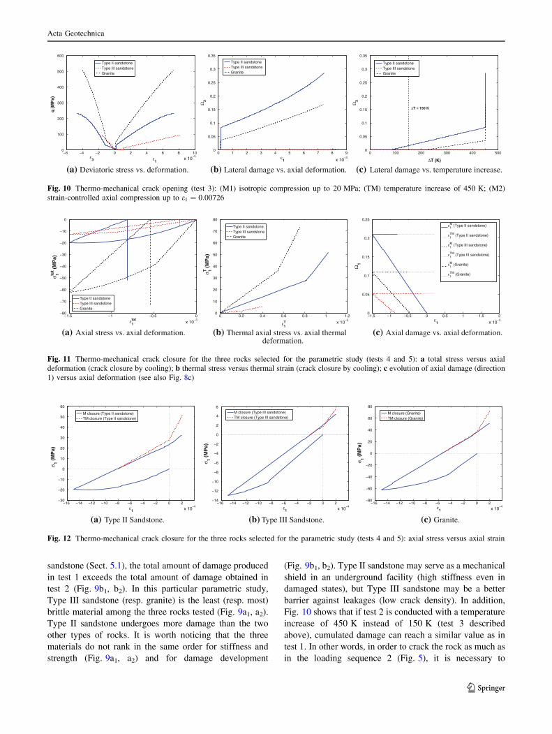
Fig. 10 shows that if test 2 is conducted with a temperature
increase of 450 K instead of 150 K (test 3 described
above), cumulated damage can reach a similar value as in
test 1. In other words, in order to crack the rock as much as
in the loading sequence 2 (Fig. 5), it is necessary to
−6 −4 −2 0 2 4 6 8 10
x 10−3
0
100
200
300
400
500
600
ε3
q (
MP
a)
Type II sandstoneType III sandstoneGranite
ε1
0 1 2 3 4 5 6 7 8 9
x 10−3
0
0.05
0.1
0.15
0.2
0.25
0.3
0.35
ε1
Ω3
Type II sandstoneType III sandstoneGranite
0 100 200 300 400 5000
0.05
0.1
0.15
0.2
0.25
0.3
0.35
ΔT (K)
Ω3
Type II sandstoneType III sandstoneGranite
ΔT = 150 K
(a) Deviatoric stress vs. deformation. (b) Lateral damage vs. axial deformation. (c) Lateral damage vs. temperature increase.
Fig. 10 Thermo-mechanical crack opening (test 3): (M1) isotropic compression up to 20 MPa; (TM) temperature increase of 450 K; (M2)
strain-controlled axial compression up to e1 ¼ 0:00726
−1.5 −1 −0.5 0
x 10−3
−80
−70
−60
−50
−40
−30
−20
−10
0
ε1tot
σ 1tot (
MP
a)
Type II sandstoneType III sandstoneGranite
0 0.2 0.4 0.6 0.8 1 1.2
x 10−3
0
10
20
30
40
50
60
70
80
ε1T
σ 1T (
MP
a)
Type II sandstoneType III sandstoneGranite
−1.5 −1 −0.5 0 0.5 1 1.5 2
x 10−3
0
0.05
0.1
0.15
0.2
0.25
ε1
Ω1
ε1M (Type II sandstone)
ε1TM (Type II sandstone)
ε1M (Type III sandstone)
ε1TM (Type III sandstone)
ε1M (Granite)
ε1TM (Granite)
(a) Axial stress vs. axial deformation. (b) Thermal axial stress vs. axial thermaldeformation.
(c) Axial damage vs. axial deformation.
Fig. 11 Thermo-mechanical crack closure for the three rocks selected for the parametric study (tests 4 and 5): a total stress versus axial
deformation (crack closure by cooling); b thermal stress versus thermal strain (crack closure by cooling); c evolution of axial damage (direction
1) versus axial deformation (see also Fig. 8c)
−16 −14 −12 −10 −8 −6 −4 −2 0 2
x 10−4
−30
−20
−10
0
10
20
30
40
50
60
ε1
σ 1 (M
Pa)
M closure (Type II sandstone)TM closure (Type II sandstone)
−16 −14 −12 −10 −8 −6 −4 −2 0 2
x 10−4
−14
−12
−10
−8
−6
−4
−2
0
2
4
6
ε1
σ 1 (M
Pa)
M closure (Type III sandstone)TM closure (Type III sandstone)
−16 −14 −12 −10 −8 −6 −4 −2 0 2
x 10−4
−80
−60
−40
−20
0
20
40
60
80
ε1
σ 1 (M
Pa)
M closure (Granite)TM closure (Granite)
(a) Type II Sandstone. (b) Type III Sandstone. (c) Granite.
Fig. 12 Thermo-mechanical crack closure for the three rocks selected for the parametric study (tests 4 and 5): axial stress versus axial strain
Acta Geotechnica
123
Page 18
multiply the temperature increase by about three during the
heating phase preceding the mechanical loading phase.
In tests 4 and 5 (extension followed by relaxation and
closure by cooling or compression), the plots are positioned
in the same order as in tests 1, 2, and 3. Type II sandstone
is the most damaged rock (Fig. 11c), granite is the most
brittle, and Type III sandstone is the most ductile (Fig. 11a,
b). Note that for the material parameters adopted (Table 6),
granite tensile strength turns out to be of the order of
60 MPa (Fig. 11a), whereas reference values reported for
granite tensile strength are in the range of 7 to 25 MPa
[34]. The constitutive parameters used for the simulations
were calibrated by other authors from stress/stress curves
obtained in triaxial compression tests. The discrepancy
observed for granite tensile strength suggests that the cal-
ibration data set should be complemented by experimental
results from tensile tests. Fig. 12 shows the stress/strain
curves obtained for the three rocks under study. In test 5
(mechanical compression closes the cracks), the slope of
the curve comes back to its initial value (virgin material) as
soon as deformation is compressive (positive with the soil
mechanics sign convention). In test 4, the three rocks
exhibit different behavior upon closure of the cracks during
the cooling phase. Type II sandstone tends to harden during
the closure phase, i.e., the point at zero deformation is
reached for a higher total compressive stress than for the
compression closure mechanism (Fig. 12a). On the con-
trary, Type III sandstone tends to soften during the closure
phase, i.e., the point at zero deformation is reached for a
(slightly) lower total compressive stress than for the com-
pression closure mechanism (Fig. 12b). Granite is only
affected by temperature changes after full crack closure:
After the point at zero deformation has been reached, the
slope of the stress/strain curves becomes equal to the slope
of the thermo-mechanical loading curve of the virgin
material—steeper than the slope of the mechanical loading
curve (Fig. 12c).
7 Conclusions
Temperature plays a central role in rock mechanics:
Temperature variations can induce pore fluid phase chan-
ges, as well as microstructure changes. In salt rock for
instance, ambient temperature dictates the creep mecha-
nisms originating damage and healing. Thermal gradients,
combined to mechanical boundary conditions (e.g., con-
strained displacement at a tunnel support, fixed stress value
in the far-field), can also induce cracking due to thermal
stress concentrations. The latter influences energy release
rates in the same way as pure mechanical stress concen-
trations calculated in fracture mechanics. The literature
review presented in the first part of this paper summarizes
observations made in the laboratory during thermo-
mechanical stress paths imposed to different types of rock
and provides an overview of the constitutive models pro-
posed within the framework of continuum damage
mechanics.
Following that framework, the thermodynamic model
proposed herein aims to predict stiffness anisotropy
induced by thermo-mechanical crack opening and closure
in rock. Damage is defined as the second-order crack
density tensor [45]. Halm and Dragon’s model [28] is used
as a basis to postulate the form of the free energy, which is
expressed in the form of a polynomial of deformation,
temperature, and damage. Thermo-elastic energy potentials
are made dependent on damage—by assuming that in
addition to the bulk modulus, heat capacity is affected by
damage. Stress and the damage-driving force are derived
from the free energy, and conjugation relationships indicate
that stress and damage-driving force depend on internal
variables (such as damage) and external variables (e.g.,
strain and temperature). The energy release rate controlling
damage propagation is a modified damage-driving force.
The damage criterion controls mode I crack propagation,
captures temperature-induced decrease of rock strength,
and accounts for the increase in energy release rate nec-
essary to propagate cracks in a damaged medium. Crack
closure is modeled through unilateral effects produced on
rock stiffness. The thermo-mechanical damage model was
calibrated and verified against experimental stress/strain
curves obtained by Sulem and Ouffroukh [77] during
drained triaxial compression tests conducted on saturated
sandstone.
The set of calibrated constitutive parameters was then
used to simulate the evolution of stiffness, deformation,
damage, and released energy for various stress paths. Crack
opening induced by thermo-mechanical stresses was stud-
ied by simulating a triaxial compression test conducted in
three phases: (1) an isotropic confining phase followed by
an axial compression, followed by a heating phase; or (2)
an isotropic confining phase followed by a heating phase,
followed by an axial compression. Results show that under
anisotropic mechanical boundary conditions, cracks can be
produced during heating. Higher ambient temperature
increases the lateral expansion and produces more damage.
In the proposed formulation, the thermo-mechanical energy
release rate not only increases with thermal dilation, but
also decreases with ambient temperature. If heating is
applied before the mechanical compression load, there is a
temperature threshold, below which the rock behaves
elastically. Thermo-mechanical crack closure was studied
by simulating a uniaxial tension test followed by a stress
relaxation phase, followed by a compression phase: (1)
either by cooling with fixed axial displacements, (2) or by
mechanical axial compression. The degradation of stiffness
Acta Geotechnica
123
Page 19
due to tensile stress and recovery of stiffness due to uni-
lateral effects are well captured. The simulation of the
confined cooling phase also illustrates the capability of the
model to predict crack closure induced by the coupled
thermo-mechanical stresses.
A parametric study was performed to compare the sets
of damage parameters needed to model the strength and
stiffness evolution of three types of rocks. Stress paths
were the same as in the preceding analysis of crack opening
and closure. It is shown that proper model calibration
allows predicting the increase in temperature needed to
propagate damage before mechanical compression, as
compared to the temperature needed to propagate damage
after cracks have already been produced by mechanical
compression. It is also noted that the model can capture
hardening and softening during thermo-mechanical closure
(for damage parameters typical of sandstone). These
numerical observations may guide the choice of rock
material used in geotechnical design, especially for nuclear
waste disposals or compressed-air storage facilities. A
proper understanding of the differences of behavior noted
between the types of rock tested would require a multi-
scale model, accounting for the various microscopic pro-
cesses occurring at the grain scale. This will be the
objective of a future work focused on rock healing and
mechanical recovery.
Acknowledgments The authors truly appreciate the most insightful
comments and advice provided by Dr. M. Veveakis (CSIRO, Perth,
Australia) to improve the section presenting thermodynamic modeling
issues. During the discussions, the second author particularly enjoyed
sharing journal articles, ideas, and research vision about thermody-
namics and geomechanics.
References
1. Abu Al-Rub R, Voyiadjis G (2003) On the coupling of aniso-
tropic damage and plasticity models for ductile materials. Int J
Solids Struct 40(11):2611–2643
2. Arson C, Gatmiri B (2010) Numerical study of a thermo-hydro-
mechanical damage model for unsaturated porous media. Ann
Solid Struct Mech 1(2):59–78
3. Arson C, Gatmiri B (2012) Thermo-hydro-mechanical modeling
of damage in unsaturated porous media: theoretical framework
and numerical study of the edz. Int J Numer Anal Methods
Geomech 36(3):272–306
4. Arson C, Xu H, Chester F (2012) On the definition of damage in
time-dependent healing models for salt rock. Geotech Lett
2:67–71
5. Besuelle P, Desrues J, Raynaud S (2000) Experimental charac-
terisation of the localisation phenomenon inside a vosges sand-
stone in a triaxial cell. Int J Rock Mech Min Sci 37(8):1223–1237
6. Bryson L, Salehian A (2011) Performance of constitutive models
in predicting behavior of remolded clay. Acta Geotech
6(3):143–154
7. Cauvin A, Testa R (1999) Damage mechanics: basic variables in
continuum theories. Int J Solids Struct 36(5):747–761
8. Cekerevac C, Laloui L (2004) Experimental study of thermal
effects on the mechanical behaviour of a clay. Int J Numer Anal
Methods Geomech 28(3):209–228
9. Cervera M, Oliver J, Prato T (1999) Thermo-chemo-mechanical
model for concrete. I: hydration and aging. J Eng Mech
125(9):1018–1027
10. Chaboche JL (1992) Damage induced anisotropy: on the diffi-
culties associated with the active/passive unilateral condition. Int
J Damage Mech 1(2):148–171
11. Chaboche JL (1993) Development of continuum damage
mechanics for elastic solids sustaining anisotropic and unilateral
damage. Int J Damage Mech 2(4):311–329
12. Chaki S, Takarli M, Agbodjan W (2008) Influence of thermal
damage on physical properties of a granite rock: porosity, per-
meability and ultrasonic wave evolutions. Constr Build Mater
22(7):1456–1461
13. Chan K, Bodner S, Munson D (2001) Permeability of WIPP salt
during damage evolution and healing. Int J Damage Mech
10(4):347–375
14. Chen Y, Zhou C, Jing L (2010) Numerical modeling of coupled
thermo-mechanical response of a rock pillar. J Rock Mech
Geotech Eng 2(3):262–273
15. Choo J, Kim Y, Lee J, Yun T, Lee J, Kim Y (2013) Stress-
induced evolution of anisotropic thermal conductivity of dry
granular materials. Acta Geotech 8:91–106
16. Collins I, Houlsby G (1997) Application of thermomechanical
principles to the modelling of geotechnical materials. Proc R Soc
Lond Ser A Math Phys Eng Sci 453(1964):1975–2001
17. Cordebois J, Sidoroff F (1982) Endommagement anisotrope en
elasticite et plasticite. J de Mecanique theorique et appliquee
45–60
18. Cowin S (1985) The relationship between the elasticity tensor and
the fabric tensor. Mech Mater 4(2):137–147
19. David C, Menendez B, Darot M (1999) Influence of stress-
induced and thermal cracking on physical properties and micro-
structure of la peyratte granite. Int J Rock Mech Min Sci
36(4):433–448
20. de Borst R, Pamin J, Geers MG (1999) On coupled gradient-
dependent plasticity and damage theories with a view to locali-
zation analysis. Eur J Mech Solids 18(6):939–962
21. Desmorat R (2006) Positivite de la dissipation intrinseque d’une
classe de modeles d’endommagement anisotropes non standards.
C R Mec 334(10):587–592
22. Dormieux L, Kondo D, Ulm FJ (2006) A micro mechanical
analysis of damage propagation in fluid-saturated cracked media.
C R Mec 334(7):440–446
23. Dragon A, Halm D, Desoyer T (2000) Anisotropic damage in
quasi-brittle solids: modelling, computational issues and appli-
cations. Comput Methods Appl Mech Eng 183(3):331–352
24. Fortin J, Stanchits S, Vinciguerra S, Gueguen Y (2011) Influence
of thermal and mechanical cracks on permeability and elastic
wave velocities in a basalt from mt. etna volcano subjected to
elevated pressure. Tectonophysics 503(1):60–74
25. Gawin D, Baggio P, Schrefler BA (1995) Coupled heat, water and
gas flow in deformable porous media. Int J Numer Methods
Fluids 20(8–9):969–987
26. Giot R, Giraud A, Guillon T, Auvray C (2012) Three-dimensional
poromechanical back analysis of the pulse test accounting for
transverse isotropy. Acta Geotech 7(3):151–165
27. Grujovic N, Divac D, Zivkovic M, Slavkovic R, Milivojevic N,
Milivojevic V, Rakic D (2013) An inelastic stress integration
algorithm for a rock mass containing sets of discontinuities. Acta
Geotech
28. Halm D, Dragon A (1998) An anisotropic model of damage and
frictional sliding for brittle materials. Eur J Mech Solids
17(3):439–460
Acta Geotechnica
123
Page 20
29. Halm D, Dragon A (2002) Modelisation de l’endommagement
par mesofissuration du granite. Revue Francaise de Genie Civil
17:21–33
30. Heard H, Page L (1982) Elastic moduli, thermal expansion, and
inferred permeability of two granites to 350 c and 55 megapascals.
J Geophys Res Solid Earth (1978–2012) 87(B11):9340–9348
31. Hejazi Y, Dias D, Kastner R (2008) Impact of constitutive models
on the numerical analysis of underground constructions. Acta
Geotech 3:251–258
32. Heuze F (1983) High-temperature mechanical, physical and
thermal properties of granitic rocks—a review. Int J Rock Mech
Min Sci Mech Abstr 20(1):3–10
33. Homand F, Chiarelli AS, Hoxha D (2002) Caracteristiques phy-
siques et mecaniques du granite de la vienne et de l’argilite de
l’est. Revue francaise de genie civil 6(1):11–20
34. Homand-Etienne F, Houpert R (1989) Thermally induced mi-
crocracking in granites: characterization and analysis. Int J Rock
Mech Min Sci Mech Abstr 26(2):125–134
35. Hou Z (2003) Mechanical and hydraulic behavior of rock salt in
the excavation disturbed zone around underground facilities. Int J
Rock Mech Min Sci 40(5):725–738
36. Houlsby G, Puzrin A (2006) Principles of Hyperplasticity: An
Approach to Plasticity Theory Based on Thermodynamic Prin-
ciples. Springer, Berlin
37. Hueckel T, Baldi G (1990) Thermoplasticity of saturated clays:
experimental constitutive study. J Geotech Eng 116(12):
1778–1796
38. Hueckel T, Borsetto M (1990) Thermoplasticity of saturated soils
and shales: constitutive equations. J Geotech Eng 116(12):
1765–1777
39. Hueckel T, Pellegrini R (2002) Reactive plasticity for clays:
application to a natural analog of long-term geomechanical
effects of nuclear waste disposal. Eng Geol 64(2):195–215
40. Hunsche U, Hampel A (1999) Rock salt—the mechanical prop-
erties of the host rock material rock salt—the mechanical prop-
erties of the host rock material for a radioactive waste repository.
Eng Geol 52(3-4):271–291
41. Hutter M, Tervoort T (2008) Continuum damage mechanics:
combining thermodynamics with a thoughtful characterization of
the microstructure. Acta Mech 201(1-4):297–312
42. Inada Y, Kinoshita N, Ebisawa A, Gomi S (1997) Strength and
deformation characteristics of rocks after undergoing thermal
hysteresis of high and low temperatures. Int J Rock Mech Min Sci
34(3–4):140.e1–140.e14
43. Jeong Hs, Kang Ss, Obara Y (2007) Influence of surrounding
environments and strain rates on the strength of rocks subjected
to uniaxial compression. Int J Rock Mech Min Sci 44(3):321–331
44. Jia Y, Wileveau Y, Su K, Duveau G, Shao JF (2007) Thermo-
hydro-mechanical modelling of an in situ heating experiment.
Geotechnique 57(10):845–855
45. Kachanov M (1992) Effective elastic properties of cracked solids:
critical review of some basic concepts. Appl Mech Rev
45(8):304–335
46. Keller A, Hutter K (2011) On the thermodynamic consistency of
the equivalence principle in continuum damage mechanics.
J Mech Phys Solids 59(5):1115–1120
47. Keshavarz M, Pellet F, Loret B (2010) Damage and changes in
mechanical properties of a gabbro thermally loaded up to
1,000 �C. Pure Appl Geophys 167(12):1511–1523
48. Konietzky H, Heftenberger A, Feige M (2009) Life-time pre-
diction for rocks under static compressive and tensile loads: a
new simulation approach. Acta Geotech 4:73–78
49. Laloui L (2001) Thermo-mechanical behaviour of soils. Revue
francaise de genie civil 5(6):809–843
50. Laloui L, Cekerevac C (2003) Thermo-plasticity of clays: an
isotropic yield mechanism. Comput Geotech 30(8):649–660
51. Lan H, Martin C, Andersson J (2013) Evolution of in situ rock
mass damage induced by mechanical–thermal loading. Rock
Mech Rock Eng 46(1):153–168
52. Lecampion B (2010) Stress-induced crystal preferred orientation
in the poromechanics of inpore crystallization. J Mech Phys
Solids 58:1701–1715
53. Lemaitre J, Desmorat R (2005) Engineering damage mechanics.
Ductile, creep, fatigue and brittle failure. Springer, Berlin
54. Levasseur S, Collin F, Charlier R, Kondo D (2011) A two-scale
anisotropic damage model accounting for initial stresses in mi-
crocracked materials. Eng Fract Mech 78:1945–1956
55. Li L, Tang C, Wang S, Yu J (2013) A coupled thermo-hydro-
logic-mechanical damage model and associated application in a
stability analysis on a rock pillar. Tunn Undergr Space Tech
34:38–53
56. Liang WG, Xu SG, Zhao YS (2006) Experimental study of
temperature effects on physical and mechanical characteristics of
salt rock. Rock Mech Rock Eng 39(5):469–482
57. Lion M, Skoczylas F, Ledesert B (2005) Effects of heating on the
hydraulic and poroelastic properties of bourgogne limestone. Int J
Rock Mech Min Sci 42(4):508–520
58. Liu E, Xing H (2009) A double hardening thermo-mechanical
constitutive model for overconsolidated clays. Acta Geotech4(1):1–6
59. Liu Z, Yu X (2011) Coupled thermo-hydro-mechanical model for
porous materials under frost action: theory and implementation.
Acta Geotech 6(2):51–65
60. Liu J, Xie H, Hou Z, Yang C, Chen L (2013) Damage evolution
of rock salt under cyclic loading in unixial tests. Acta Geotech
61. Liu R, Mao X, Zhang L, Ma D (2013) Thermal properties of
mudstone at high temperature. Int J Geomech
62. Lu B, Torquato S (1992) Nearest-surface distribution functions
for poly-dispersed particle systems. Phys Rev A 45:5530–5544
63. Lubarda V, Krajcinovic D (1993) Damage tensors and the crack
density distribution. Int J Solids Struct 30(20):2659–2677
64. Luong MP (1990) Tensile and shear strengths of concrete and
rock. Eng Fract Mech 35(1–3):127–135
65. Mao XB, Zhang LY, Li TZ, Liu HS (2009) Properties of failure
mode and thermal damage for limestone at high temperature. Min
Sci Technol (China) 19(3):290–294
66. Mazars J, Berthaud Y, Ramtani S (1990) The unilateral behaviour
of damaged concrete. Eng Fract Mech 35(4–5):629–635
67. McDermott CI, Randriamanjatosoa ARL, Tenzer H, Kolditz O
(2006) Simulation of heat extraction from crystalline rocks: The
influence of coupled processes on differential reservoir cooling.
Geothermics 35(3):321–344
68. Nasseri M, Schubnel A, Benson P, Young R (2009) Common
evolution of mechanical and transport properties in thermally
cracked westerly granite at elevated hydrostatic pressure. Pure
Appl Geophys 166(5-7):927–948
69. Oda M (1984) Similarity rules of crack geometry in statistically
homogeneous rock masses. Mech Mater 3(2):119–129
70. Pecqueur G (1995) Etude experimentale et modelisation du
comportement d’une craie et d’un gres en torsion. PhD thesis,
University of Lille I
71. Reuschle T, Haore SG, Darot M (2006) The effect of heating on
the microstructural evolution of la peyratte granite deduced from
acoustic velocity measurements. Earth and Planetary Science
Letters 243(3–4):692–700
72. Rutqvist J, Freifeld B, Min KB, Elsworth D, Tsang Y (2008)
Analysis of thermally induced changes in fractured rock perme-
ability during 8 years of heating and cooling at the yucca mountain
drift scale test. Int J Rock Mech Min Sci 45(8):1373–1389
73. Schrefler BA, Zhan X, Simoni L (1995) A coupled model for
water flow, airflow and heat flow in deformable porous media. Int
J Numer Methods Heat Fluid Flow 5(6):531–547
Acta Geotechnica
123
Page 21
74. Shao J, Zhou H, Chau K (2005) Coupling between anisotropic
damage and permeability variation in brittle rocks. Int J Numer
Anal Methods Geomech 29(12):1231–1247
75. Shi Y, Zhu Zd, Li Zj (2008) Deformation characteristics of deep-
buried caverns considering thermal effect. Adv Sci Technol
Water Resour (China) 28(3):33–36
76. Stabler J, Baker G (2000) On the form of free energy and specific
heat in coupled thermo-elasticity with isotropic damage. Int J
Solids Struct 37(34):4691–4713
77. Sulem J, Ouffroukh H (2006) Shear banding in drained and
undrained triaxial tests on a saturated sandstone: porosity and
permeability evolution. Int J Rock Mech Min Sci 43(2):292–310
78. Swoboda G, Yang Q (1999) An energy-based damage model of
geomaterials—I. Formulation and numerical results. Int J Solids
Struct 36(12):1719–1734
79. Tian H, Kempka T, Xu NX, Ziegler M (2012) Physical properties
of sandstones after high temperature treatment. Rock Mech Rock
Eng 45(6):1113–1117
80. Vorobiev O (2008) Generic strength model for dry jointed rock
masses. Int J Plast 24(12):2221–2247
81. Voyiadjis GZ, Shojaei A, Li G (2011) A thermodynamic con-
sistent damage and healing model for self healing materials. Int J
Plast 27(7):1025–1044
82. Wawersik W, Hannum D (1980) Mechanical behavior of new
mexico rock salt in triaxial compression up to 200 c. J Geophys
Res Solid Earth (1978–2012) 85(B2):891–900
83. Weinbrandt R, Casse F (1975) The effect of temperature on
relative and absolute permeability of sandstones. Old SPE J
15(5):376–384
84. Wong TF (1982) Effects of temperature and pressure on failure
and post-failure behavior of westerly granite. Mech Mater
1(1):3–17
85. Xianbiao M, Lianying Z, tianzhen L, haishun L (2009) Properties
of failure mode and thermal damage for properties of failure
mode and thermal damage for limestone at high temperature. Min
Sci Technol (China) 19(3):0290–0294
86. Xu H, Arson C, Busetti S (2013) Modeling the anisotropic
damaged zone around hydraulic fractures: Thermodynamic
framework and simulation of mechanical tests. In: Proc 47th US
Rock Mech Geomech Symp, San Francisco, California, USA,
paper 13–375
87. Yavuz H, Demirdag S, Caran S (2010) Thermal effect on the
physical properties of carbonate rocks. Int J Rock Mech Min Sci
47(1):94–103
88. Zhou H, Hu D, Zhang F, Shao J (2011) A thermo-plastic/visco-
plastic damage model for geomaterials. Acta Mech Solida Sin
24(3):195–208
89. Zhu H, Yan Z, Deng T, Yao J, Zeng L, Qiang J (2006) Testing
study on mechanical properties of tuff, granite and breccia after
high temperatures. Chin J Rock Mech Eng 25(10):1
Acta Geotechnica
123