Memorandum 2008-12-06 GOF-STh A Very Successful Spot Coring Test at Reykjanes During the 25 th of November 2008 a very successful spot coring test was performed at 2800 m depth in the production well RN-17 B at Reykjanes. Well RN-17 B was being reconditioned by side- tracking it out of well RN-17 at 930 m depth below the production casing, to become an inclined exploration/production well. The core test was performed in an open hole at 35° inclination with newly built coring equipment. The main benefit of the core barrel is its unique feature to enable much greater water flow-rates for cooling during coring, or up to 40 l/s, as compared to conventional core barrels which enable an order of magnitude lower flow rates. A 9.3 m hydrothermally altered hyaloclastite breccia was cored with so to speak 100% core recovery. The newly purchased ICDP core barrel and bits proved just perfect for our IDDP purpose of coring in high temperature wells, and only minor improvement on the equipment is needed before further spot coring in the IDDP-1 well in Krafla next summer. The core bit experienced some 280°C during coring, and the entire operation took some 33 hours rig time. Background. In 2006 a decision by IDDP was reached to take several spot cores in the IDDP-1 well, instead of attempting a continuous wireline coring of the bottom section. Spot cores are anticipated from both the expected transition zone to supercritical from 2400-3500 m depth, and from within the supercritical zone itself between 3500-4500 m. Since, information was obtained from service companies for the coring services and also a quote for a purpose built core barrel. Based on a recommendation by Alister Skinner (ACS-Coring Services), it was decided to purchase a core barrel and bits rather than to rent. The 8 ½“x 4“ core barrel is from Rok Max and the bits from Geogem, both UK companies. The unique features are that much greater water flow-rates can be used during coring (up to 40 l/s) than for conventional ones, improving the cooling. The inner barrel bearings guides are designed with greater tolerances to compensate for the high temperature. A check valve is built into the top of the barrel sub for blow-out protection. The core bit is of the diamond impregnated type, with large cut-outs for the high flow. A trial run was recommended by the IDDP drilling technique group to collect a core, in order to find out how the system works and to give us time for improvements before the main coring starts in the IDDP-1 well in Krafla summer 2009. A suitable candidate well for the coring test on the drill rig Tyr, unexpectedly came up from within well RN-17 B at Reykjanes, which was being side-tracked below its 890 m deep production casing and expected to be drilled to some 2700 m MD at an inclination of 30°. Well RN-17 was IDDP’s former well of opportunity for deep drilling, but had to be abandoned in 2006 due to formation collapse. Unexpected opportunity to recondition this well to become an inclined exploration/production well came up early November 2008, an opportunity that IDDP could take advantage of. Originally, we intended to perform the coring test after the 9 5/8“perforated liner had been landed on the bottom. However, the HS Ltd company decided to deepen and side track the well a bit further after 2798.5 m depth had been reached, in an attempt to improve the well - a deepening that might have excluded IDDP’s chance to perform the coring test. Therefore, after having considered the safety and the stability of the inclined well, we decide to perform the coring test in an open hole close to 2800 m depth. The reservoir temperature at that depth is expected to be around 320°C. These are the main reasons why a trial core run was recommended: Core: • Learn what may be the core recovery %, condition, blocking, washing etc. Bit selection: • Approve the bit design based on grading of the used bit, so the additional bits can be ordered (up to 10 pcs). Function of the core catcher. Bit cooling: • Condition of the used bit. Inspect the core barrel for adverse temperature effects. • Read from temperature logger and temperature indicating strips/paint placed inside the core barrel.
Transcript
Memorandum 2008-12-06 GOF-STh
A Very Successful Spot Coring Test at Reykjanes
During the 25th of November 2008 a very successful spot coring test was performed at 2800 m depth in the production well RN-17 B at Reykjanes. Well RN-17 B was being reconditioned by side-tracking it out of well RN-17 at 930 m depth below the production casing, to become an inclined exploration/production well. The core test was performed in an open hole at 35° inclination with newly built coring equipment. The main benefit of the core barrel is its unique feature to enable much greater water flow-rates for cooling during coring, or up to 40 l/s, as compared to conventional core barrels which enable an order of magnitude lower flow rates. A 9.3 m hydrothermally altered hyaloclastite breccia was cored with so to speak 100% core recovery. The newly purchased ICDP core barrel and bits proved just perfect for our IDDP purpose of coring in high temperature wells, and only minor improvement on the equipment is needed before further spot coring in the IDDP-1 well in Krafla next summer. The core bit experienced some 280°C during coring, and the entire operation took some 33 hours rig time. Background. In 2006 a decision by IDDP was reached to take several spot cores in the IDDP-1 well, instead of attempting a continuous wireline coring of the bottom section. Spot cores are anticipated from both the expected transition zone to supercritical from 2400-3500 m depth, and from within the supercritical zone itself between 3500-4500 m. Since, information was obtained from service companies for the coring services and also a quote for a purpose built core barrel. Based on a recommendation by Alister Skinner (ACS-Coring Services), it was decided to purchase a core barrel and bits rather than to rent. The 8 ½“x 4“ core barrel is from Rok Max and the bits from Geogem, both UK companies. The unique features are that much greater water flow-rates can be used during coring (up to 40 l/s) than for conventional ones, improving the cooling. The inner barrel bearings guides are designed with greater tolerances to compensate for the high temperature. A check valve is built into the top of the barrel sub for blow-out protection. The core bit is of the diamond impregnated type, with large cut-outs for the high flow. A trial run was recommended by the IDDP drilling technique group to collect a core, in order to find out how the system works and to give us time for improvements before the main coring starts in the IDDP-1 well in Krafla summer 2009. A suitable candidate well for the coring test on the drill rig Tyr, unexpectedly came up from within well RN-17 B at Reykjanes, which was being side-tracked below its 890 m deep production casing and expected to be drilled to some 2700 m MD at an inclination of 30°. Well RN-17 was IDDP’s former well of opportunity for deep drilling, but had to be abandoned in 2006 due to formation collapse. Unexpected opportunity to recondition this well to become an inclined exploration/production well came up early November 2008, an opportunity that IDDP could take advantage of. Originally, we intended to perform the coring test after the 9 5/8“perforated liner had been landed on the bottom. However, the HS Ltd company decided to deepen and side track the well a bit further after 2798.5 m depth had been reached, in an attempt to improve the well - a deepening that might have excluded IDDP’s chance to perform the coring test. Therefore, after having considered the safety and the stability of the inclined well, we decide to perform the coring test in an open hole close to 2800 m depth. The reservoir temperature at that depth is expected to be around 320°C. These are the main reasons why a trial core run was recommended: Core:
• Learn what may be the core recovery %, condition, blocking, washing etc. Bit selection:
• Approve the bit design based on grading of the used bit, so the additional bits can be ordered (up to 10 pcs). Function of the core catcher.
Bit cooling: • Condition of the used bit. Inspect the core barrel for adverse temperature effects. • Read from temperature logger and temperature indicating strips/paint placed inside the core
barrel.
Memorandum 2008-12-06 GOF-STh
• How to optimize the bit cooling procedure with the top-drive while tripping in. How much and long to circulate at each stand?
Core barrel handling: • Are any parts missing or which can be modified that will speed up the handling of the core
barrel. • How to maximize tripping speed.
Train the crew: • Train the drillers and core hands in the proper procedures. Collect information that can be put
into a handbook for IDDP. • Collect information relative to „risk assessment“. • Work with the drillers during the coring run to establish best parameters of rotation, weight on
bit and sensitivity of recording of parameters on the console so that a profile can be built up and added to the procedures to be followed for the spot coring on the full scale IDDP-1 project in Krafla next summer.
The coring operation At 11 o’clock during the 24th November 2008 the core string was being inserted and lowered into the well. At 21:00 in the evening the torque on the slowly rotating drill string rose a bit at 2733 m depth. This was due to a relatively stiff 8 ½” drill string within the then 35°inclined well. The drill string was composed of the core barrel with a bit and 3 stabilizers followed by five 8” drill collars, a jar, three 8” drill collars, and a key hole reamer, followed by the drill pipes. After careful “reaming” through the bottom part of the well the core bit landed on the bottom at 4:30 in the morning of 25th November. The coring began at 4:34, using 40 l/s circulation rate and relatively low RPM, increasing the weight on bit and the rotation speed as the coring proceeded while decreasing the flow rate for testing the equipment. The key players in the operation on behalf of IDDP are shown in Figure 1, and from Jardboranir Ltd. on the succeeding photos, while the drilling parameters during coring are shown in detail in Figures 2, 3 and 4. According to Alister Skinner’s reviewed log note from 2nd December, the total core length should be 9.3 m core, not 9.5 m, or quoting his notes: “I’ve started to compile an operations report on the test and notice from my own notes and then from Sverrir's graphs that I stopped coring at 9.3m core depth not 9.5m as I had thought. I cannot think why I did this except I think I was trying to leave a 50cm gap for the temperature probe and instead of coring to 2807.7 and then stop, leaving 50 cm space I stopped at 2807.5 leaving 70cm.space. Core barrel run was from 2798.2 to 2807.5, This is agreed by all recordings - paper and digital. In any event this means that we will have to push the fractures even closer together in the collected core to be sure we do not achieve more than 100% recovery!.” The entire coring operation took some 33 hour rig time. Several photos of the drill core are also attached. The drill core will subsequently by scanned in our core scanner and cut and studied in detail by our science teams. The core log and labeling on the core boxes will be corrected according to the reviewed log notes. A core section will be kept at the Reykjanes power plant museum exhibition called Energy Earth – as well as the used core bit. Closer details on the coring equipment will be reported later as well as detailed description of the core itself in context with the Reykjanes geothermal system. Several IDDP related science papers have already been published on the Reykjanes system, in relation to the RN-17 well of opportunity since 2006, and other papers are underway. According to our current IDDP schedule, the drilling of the IDDP-3 well at Reykjanes (to 5 km depth), is planned for 2011-2012.
Memorandum 2008-12-06 GOF-STh
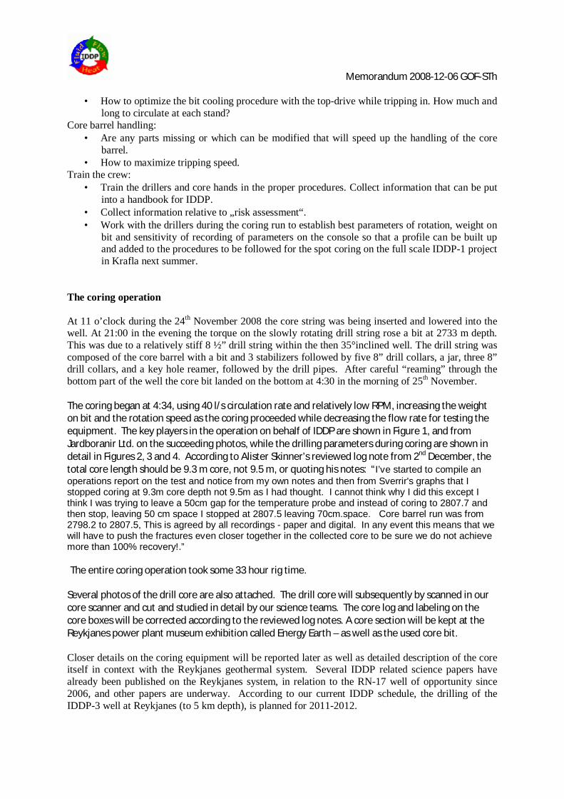
Figure 1. Paul Bowers, Rok Max Drilling Tools Ltd. (core barrel producer), Sverrir Thorhallsson, ISOR (IDDP’s chief drilling engineer), Hermann Guðmundsson, ISOR (formerly at driller and experienced in coring, now with the geophysical logging group at ISOR) and Alister C. Skinner, ACS-Coring Services (newly retired from BGS; a member of the IDDP SAGA group).
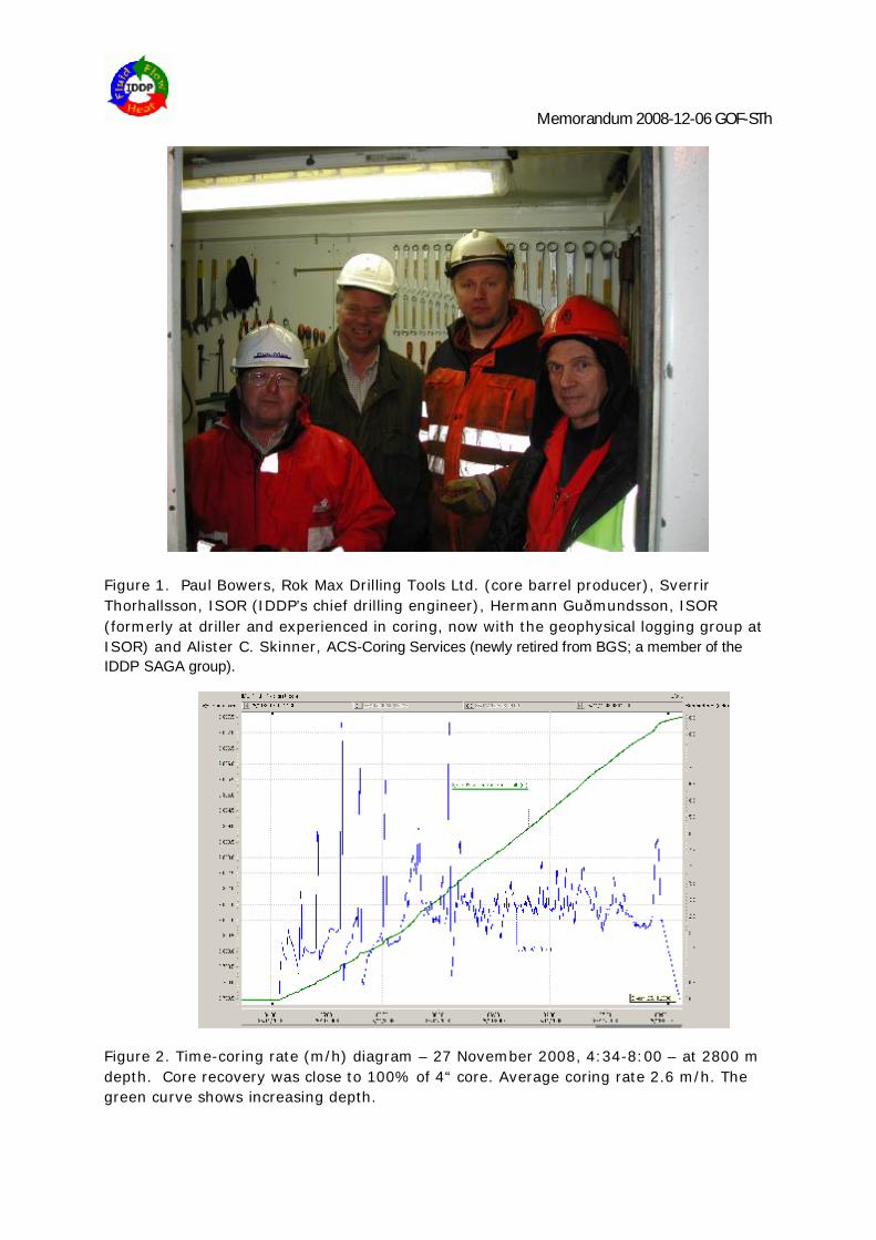
Figure 2. Time-coring rate (m/h) diagram – 27 November 2008, 4:34-8:00 – at 2800 m depth. Core recovery was close to 100% of 4“ core. Average coring rate 2.6 m/h. The green curve shows increasing depth.
Memorandum 2008-12-06 GOF-STh
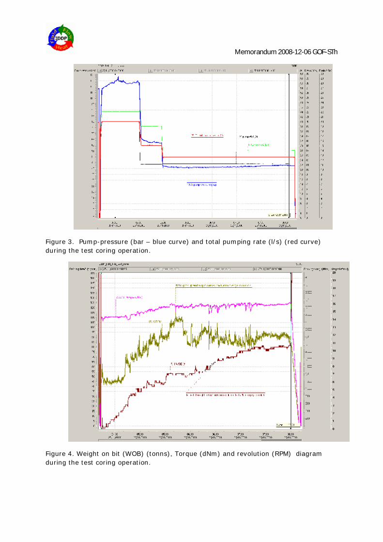
Figure 3. Pump-pressure (bar – blue curve) and total pumping rate (l/s) (red curve) during the test coring operation.
Figure 4. Weight on bit (WOB) (tonns), Torque (dNm) and revolution (RPM) diagram during the test coring operation.
Memorandum 2008-12-06 GOF-STh
Figure 5. The core bit and the core catcher.
Figure 6. A chamber for temperature monitoring tools during coring.
Memorandum 2008-12-06 GOF-STh
Figure 7. Core barrel on its way down to the drill hole.
Figure 8. The bottom of the hole at 2800 m is on the basalt plateau to the right of the fault some 800 m away from the TYR rig (in the background). The Reykjanes lighthouse is seen on the left.
Memorandum 2008-12-06 GOF-STh
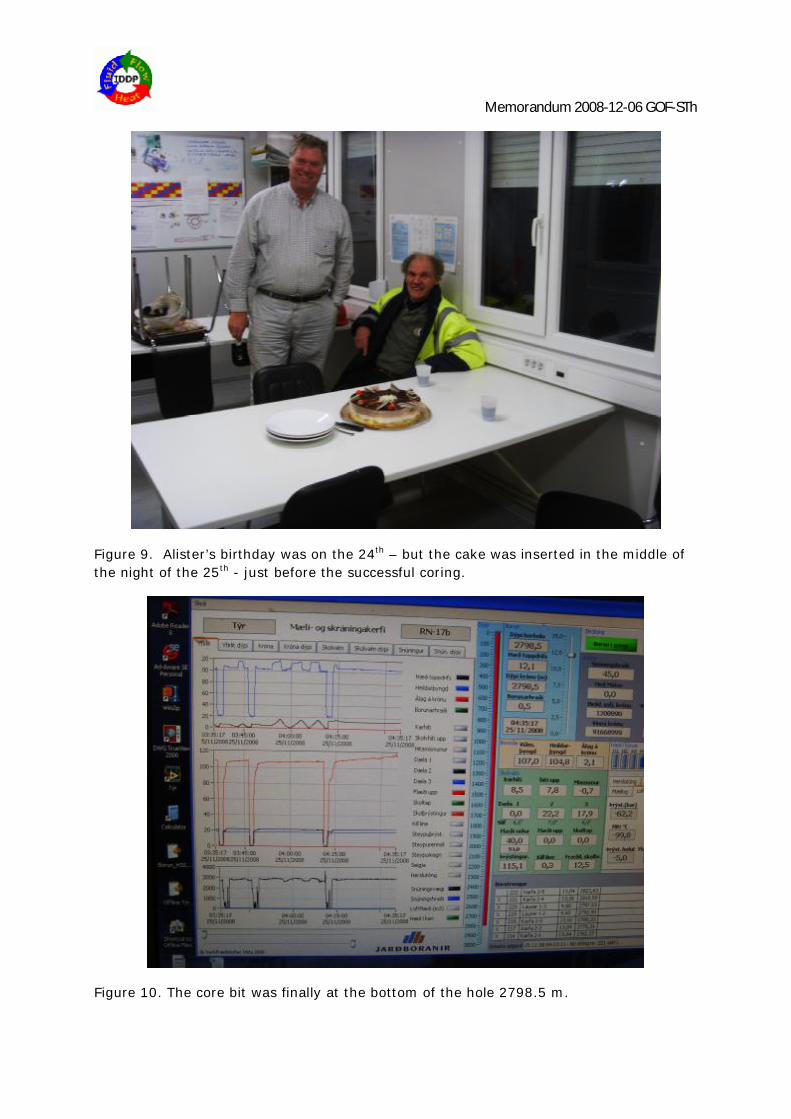
Figure 9. Alister’s birthday was on the 24th – but the cake was inserted in the middle of the night of the 25th - just before the successful coring.
Figure 10. The core bit was finally at the bottom of the hole 2798.5 m.
Memorandum 2008-12-06 GOF-STh
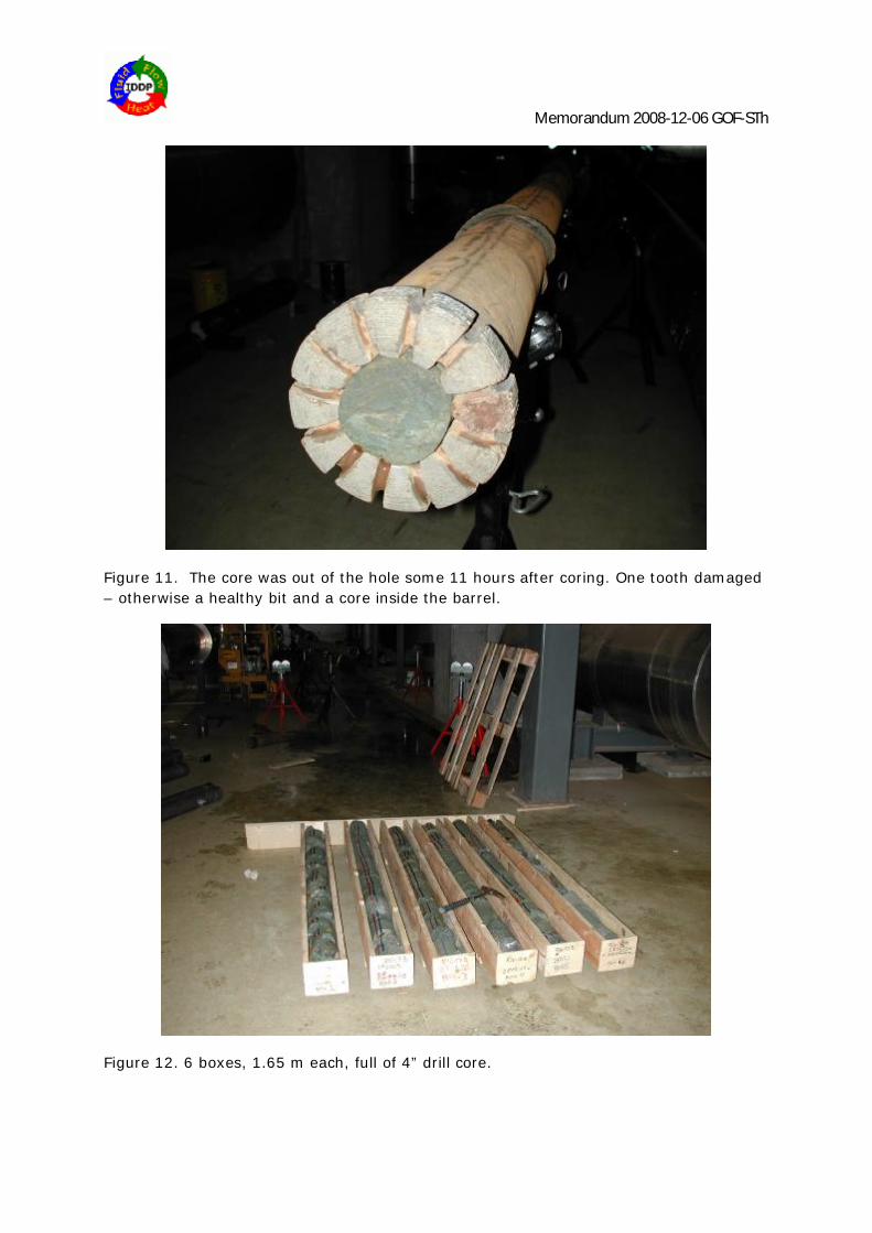
Figure 11. The core was out of the hole some 11 hours after coring. One tooth damaged – otherwise a healthy bit and a core inside the barrel.
Figure 12. 6 boxes, 1.65 m each, full of 4” drill core.
Memorandum 2008-12-06 GOF-STh
Figure 13. A close up of the core boxes containing green hyaloclastite breccia.
Figure 14. Preliminary inspection of the drill core. The core contains base metal sulphides, epidote, actinolite and quartz in abundance, but no calcite (suggesting T>300°C).
Memorandum 2008-12-06 GOF-STh
Figure 15. The steam separation house of the Reykjanes power plant was used to handle the coring equipment and to have a quick look at the core.
Figure 16. And what a core!
Memorandum 2008-12-06 GOF-STh
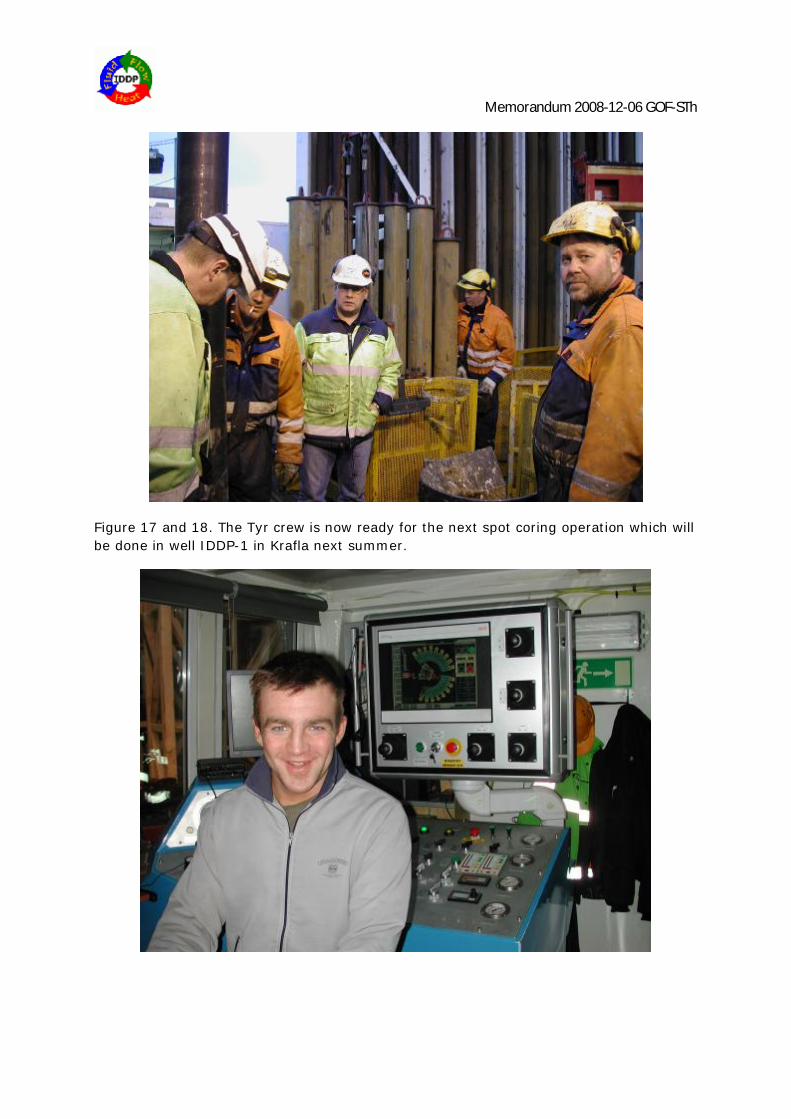
Figure 17 and 18. The Tyr crew is now ready for the next spot coring operation which will be done in well IDDP-1 in Krafla next summer.
Memorandum 2008-12-06 GOF-STh
Figure 19. The drill rig Tyr is scheduled for the IDDP-1 well in Krafla in March 2009 – and will begin by drilling a 17 ½” well from 800 m to about 2400 m depth, followed by inserting and cementing of the 13 3/8” casing. Then a 12 ¼” drilling to 3500 m – including several spot cores, and casing by 9 5/8” cemented casing. The well will be completed by 8 ½” rotary drilling to 4500 m depth, including several spot cores.
The rig proved quite nice for spot coring. Only minor adjustment on the drilling panel – mostly to increase the resolution of the drilling parameters during coring will be done before the next coring operation. We would also like to have a higher tolerance temperature memory tool in the bottom hole assembly during coring if possible – something that will be looked at during the next few months until the Krafla coring.