41
A VHDL Tutorial ENG2410
| Date post: | 01-Jan-2016 |
| Category: |
Documents |
| Upload: | scarlett-terry |
| View: | 231 times |
| Download: | 0 times |

A VHDL Tutorial
ENG2410

ENG241/VHDL Tutorial 2
Goals
• Introduce the students to the following:– VHDL as Hardware description language. – How to describe your design using VHDL.– Why use VHDL as an alternative to schematic
capture.– Syntax of VHDL.– Hierarchical Design.

ENG241/VHDL Tutorial 3
VHDL
• VHDL stands for VHSIC (Very High Speed Integrated Circuit) HDL (Hardware Description Language).
• HDLs are used to model hardware • VHDL is used to describe digital systems.• Initially was intented for documentation,
and simulation. • Now used for synthesis.

ENG241/VHDL Tutorial 4
VHDL program components
• Library Declaration.• Entity Declaration.• Architecture Body.

ENG241/VHDL Tutorial 5
Library Declaration
• This declare standard data types and some procedures used in modelling the design.
Library IEEE; -- Declare the IEEE library
Use IEEE.STD_LOGIC.1164.all; --Use package 1164
• Packages are containers for related functional units.• Library contains declaration of different packages and components.

ENG241/VHDL Tutorial 6
• Entity describes the input/output configuration for the modelled system.
entity and2 isport ( a,b in : std_logic;
f out : std_logic);end and2;
Entity Declaration
Port Name
Data Type
Direction
Entity Name

ENG241/VHDL Tutorial 7
Architecture Body
• Architecture body is used to describe the internal structure of the modelled system.
architecture dataflow of and2 is--signal and component declaration here
beginf <= a and b;
end dataflow;Architecture Name
Entity
Concurrent Statements

ENG241/VHDL Tutorial 8
Library IEEE;Use IEEE.STD_LOGIC.1164.all;
entity and2 isport ( a,b in : std_logic;
f out : std_logic);end and2;
architecture dataflow of and2 isbegin
f <= a and b; --Data flow modelend dataflow;
Complete Model

ENG241/VHDL Tutorial 9
entity and2 is --Three Model Stylesport ( a,b in : std_logic; --1. Data Flow
f out : std_logic); --2. Structuredend and2; --3. Behavioural
Complete Model
architecture dataflow of and2 isbegin
f <= a and b; end dataflow;
architecture behaviour of and2 isbeginand_proc: process (a,b)begin if a = b then f <= ‘1’; else f <= ‘0’; end if;end behaviour;
architecture structured of and2 isbegin
u1 : oldand2 port map (a,b,f);end structured;

ENG241/VHDL Tutorial 10
Data Types
• Every data object in VHDL can hold a value that belongs to a set of values.
• This set of values is specified using a type declaration.– Predefined types.– User defined types

ENG241/VHDL Tutorial 11
Predefined Data Types
• Boolean “False, True”• Bit (0,1)
– Bit_Vector -array of bits (100011)
• Character ‘a’ ,”ASCII”• INTEGER (3 , 12)• REAL (1.5 , 0.23)

ENG241/VHDL Tutorial 12
STD_LOGIC Data Type
• This data type is used to define signals that could be found in standard digital system.
• This data type is defined in the IEEE library Package IEEE.STD_LOGIC.1164.
• It could have the following values:– ‘1’ => Forcing Logic 1– ‘0’ => Forcing Logic 0– ‘Z’ => High Impedance– ‘U’ => Un-initialized– ‘X’ => Forcing Unknown– ‘-’ => Don’t care– ‘W’=> Weak Unknown– ‘L’ => Weak 0– ‘H’ => Weak 1

ENG241/VHDL Tutorial 13
STD_LOGIC_VECTOR Data Type
• Array of STD_LOGIC.• It could be used to represent a bus in digital
systems.--MSB in the left and LSB in the rightsignal data_bus : std_logic_vector (7 downto 0);
--LSB in the left and MSB in the rightsignal data_bus : std_logic_vector (0 to 7);

ENG241/VHDL Tutorial 14
STD_LOGIC_VECTOR Data Type
• Signals or Variables of this data type could be accessed completely , partially, or bit by bit.
--MSB in the left and LSB in the rightsignal data_bus : std_logic_vector (7 downto 0);signal data_bus_nipple : std_logic_vector (3 downto 0);
--Inside the architecturedata_bus_nipple <= “0101”; --load data in 4 bit signaldata_bus (3 downto 0) <= data_bus_nipple; --connect it to
the first 4data_bus (6 downto 4) <= “100”; --assign the other 3 bitsdata_bus (7) <= not data_bus_nipple (3); --and the final bit

ENG241/VHDL Tutorial 15
Concurrent Statements• Inside the architecture body we use concurrent statements.
– Signal assignmentf <= a and b;
– Processesand_proc : process (a,b)begin
. --sequential statements .
end process;– Component instantiation
u1 : and2 port map (as,bs,fs);

ENG241/VHDL Tutorial 16
Concurrent Statements
• The concurrent statements are executed without any specific order.
• The architecture body could contain any combination of the 3 types of concurrent statements.

ENG241/VHDL Tutorial 17
Concurrent Statements
This circuit could be modelled as following:f<= z or w;z<= x and y;x<= not a;w<= a and b;y<= not b;
ENG241/VHDL Tutorial 18
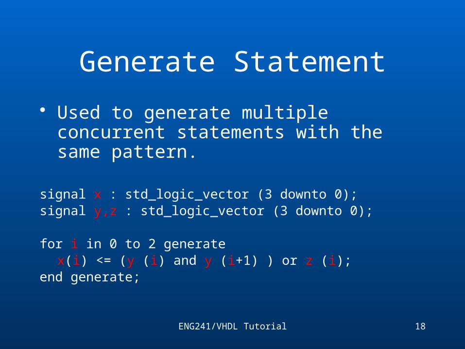
Generate Statement
• Used to generate multiple concurrent statements with the same pattern.
signal x : std_logic_vector (3 downto 0);signal y,z : std_logic_vector (3 downto 0);
for i in 0 to 2 generatex(i) <= (y (i) and y (i+1) ) or z (i);
end generate;

ENG241/VHDL Tutorial 19
Process Block
proc_name : process (x,y)variable z: std_logic;begin
z:= x or y;if z= ‘0’ and y=‘1’ then
m<= z;else
m<= not x;end if;
end process;Note: The process block is considered a single concurrent
statement.
Process name
Sensitivity List
Variable Deceleration
Sequential Statements

ENG241/VHDL Tutorial 20
Component Instantiation
• It has two parts:– Component Declaration in arch. Body before the begin line:
component and2 --like entity declarationport (a,b : in STD_LOGIC;
f : out STD_LOGIC);end component;
– Component Instantiation inside the arch. Body:u1: and2 port map (a=>x,f=>z,b=>y); --No order
requiredor simply
u1: and2 port map (x,y,z); --Has to be in order
Component port Arch. Signal

ENG241/VHDL Tutorial 21
Sequential Statements
• Sequential Statements are used inside the process, function or procedure blocks.
• This may be regarded as normal programming language (The order of the statements affect the result of execution).
• Can make use and change the values of signals and variables

ENG241/VHDL Tutorial 22
Sequential Statements• If statement
if x = y thenz<= ‘1’; --if true
elsez<= ‘0’; --if false
end if;• Case statement
signal y : std_logic_vector (1 downto 0);signal m : std_logic_vector (3 downto 0);
case (y) is when "00" => m <=“1001”;
when "01" => m<=“0101”; when "10" => m<=“1100”; when "11" => m<=“0001”;
when others => m<=“0000”;end case;

ENG241/VHDL Tutorial 23
Sequential Statements
• Other statements like for and while are also existing but requires attention.
signal v: std_logic_vector (3 downto 0);
for i in 0 to 2 loop --shifting right using for loop
v(i) <= v(i+1);end loop;
v(3) <= ‘0’;
Note: In this example the signal is regarded as a register.
ENG241/VHDL Tutorial 24
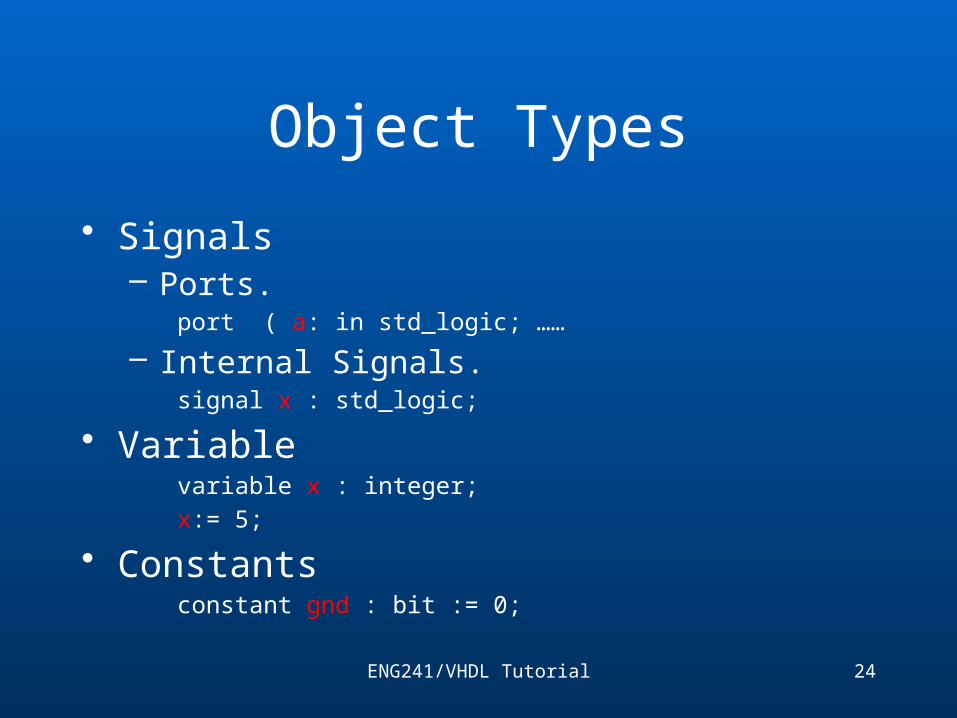
Object Types
• Signals– Ports.
port ( a: in std_logic; ……
– Internal Signals.signal x : std_logic;
• Variablevariable x : integer;x:= 5;
• Constantsconstant gnd : bit := 0;

ENG241/VHDL Tutorial 25
Signals
• Declared as ports or inside the architecture body.
– Ports.port ( a: in std_logic; ……
– Internal Signals.signal x : std_logic;
• Signals are regarded is wires in some models and as memory storage (register) in other models.
signals

ENG241/VHDL Tutorial 26
Signals
• The order of signal assignments in the same block is not important.
f<= z or w;z<= x and y;x<= not a;w<= a and b;y<= not b;

ENG241/VHDL Tutorial 27
Signals
• Signals can’t have two drivers.Note: In this example the process is considered a single driver
signal x,y,x : std_logic; --signal declaration..x<= y or z; -- first driver
uproc : process (y,z) -- second driverBegin
if y = z thenx <= ‘1’;
elsex <= ‘0’;
end if;end process;

ENG241/VHDL Tutorial 28
Conditional Signal Assignment
• Signal Assignment could be conditional.signal x : STD_LOGIC;
signal y : STD_LOGIC_VECTOR (2 downto 0);
with y select
x<= ‘0’ when “00” ,
‘0’ when “01”,
‘0’ when “10”,
‘1’ when “11”,
‘0’ when others;

ENG241/VHDL Tutorial 29
Conditional Signal Assignment
• Signal Assignment could be conditional.signal x : STD_LOGIC;
signal y : STD_LOGIC_VECTOR (2 downto 0);
x<= ‘0’ when y = “00” else
‘0’ when y = “01” else
‘0’ when y = “10” else
‘1’ when y = “11” else
‘0’;

ENG241/VHDL Tutorial 30
Variables
• Same variable concept as computer programming languages.
• Declared inside a process block ,function or procedure.uproc: process (x,y)variable z : std_logic;begin
z := ‘0’; --variable could have different valuesz := x or y;
end process;

ENG241/VHDL Tutorial 31
Variables
• The scope of the variable is inside the unit it declared in (process, function or procedure).uproc: process (x,y)variable z : std_logic;begin
z := ‘0’; --variable could have different valuesz := x or y;
end process;z:= ‘1’; -- This variable is out of scope

ENG241/VHDL Tutorial 32
• Logic operators: They are bit-wise operators( and , or , xor , xnor , nand , nor , not)
x<= y and z;a<= (b and c) or (d and e);j <= (h and i and k)
Note: Parenthesis are used to group terms.
m<= (n not k); m<= (n and (not k));g<= f and h or p; g<= (f and h) or p;
Operators

ENG241/VHDL Tutorial 33
Operators
• Arithmetic operators: Defined for predefined data types.
• For user defined data types they should be defined.- + Add , - Subtract , * multiply , / divide.
• Division is not always definedsignal v,w,x : integer;w <= 5;v <= 3;x <= w + v; -- x = 8

ENG241/VHDL Tutorial 34
Operators for STD_LOGIC
• Although STD_LOGIC type is defined in VHDL libraries. It is considered a user defined data type.
• Some extra package declaration are required.library IEEE;use IEEE.STD_LOGIC.1164;use IEEE.STD_LOGIC.ARITH.all;use IEEE.STD_LOGIC.UNSIGNED.all; --unsigned
operationsor
use IEEE.STD_LOGIC.SIGNED.all; --signed operations

ENG241/VHDL Tutorial 35
Operators for STD_LOGIC;
use IEEE.STD_LOGIC.unsigned.all;
signal x,y : std_logic_vector (3 downto 0);signal za :std_logic_vector (3 downto 0);signal zm :std_logic_vector (7 downto 0);
x<=“0101”; --5y<=“1101”; --13
za<= x + y; -- za = “0010”; = 2; wrong answerZm<= x * y; -- zm = “01000001”; 65; right answer

ENG241/VHDL Tutorial 36
Operators for STD_LOGIC;
use IEEE.STD_LOGIC.unsigned.all;
signal x,y : std_logic_vector (3 downto 0);signal za :std_logic_vector (4 downto 0);signal zm :std_logic_vector (7 downto 0);
x<=“0101”; --5y<=“1101”; --13
za<= x + y; -- za = “0010”; = 2; wrong answerZm<= x * y; -- zm = “01000001”; 65; right answer

ENG241/VHDL Tutorial 37
Operators for STD_LOGIC;
use IEEE.STD_LOGIC.unsigned.all;
signal x,y : std_logic_vector (3 downto 0);signal za :std_logic_vector (3 downto 0);signal zm :std_logic_vector (7 downto 0);
x<=“0101”; --5y<=“1101”; --13
za<= ‘0’&x + ‘0’&y; -- za = “10010”; = 18; right answer
Zm<= x * y; -- zm = “01000001”; 65; right answer
concatenation

ENG241/VHDL Tutorial 38
Operators for STD_LOGIC;
use IEEE.STD_LOGIC.signed.all;
signal x,y : std_logic_vector (3 downto 0);signal za :std_logic_vector (3 downto 0);signal zm :std_logic_vector (7 downto 0);
x<=“0101”; --5y<=“1101”; --(-3)
za<= ‘0’&x +’0’&y; -- za = “00010”; = 2 (; wrong answer
Zm<= x * y; -- zm = “11110001”; -15; right answer

ENG241/VHDL Tutorial 39
ExampleThis Figure Shows a Full Adder Circuit

ENG241/VHDL Tutorial 40
Example• First declare Xor2 ,And2 and Or3 entities and architectures
entity and2 isport ( a,b : in std_logic;
c : out std_logic );end and2;
architecture dataflow of and2 isbegin
c<= a and b;
end dataflow;
entity or3 is port ( a, b,c : in std_logic;
d : out std_logic );end and2;
architecture behavior of or3 isbegin
and3_proc : process isbegin
if a = ‘0’ and b = ‘0’ and c=‘0’ then
d <= ‘0’;
else
d <= ‘1’;
end if;
end process;
end behavior;
entity xo2 isport ( a,b : in std_logic;
c : out std_logic );end xor2;
architecture dataflow of and2 isbegin
c<= a xor b;
end dataflow;

ENG241/VHDL Tutorial 41
Example
• Now use them to implement a registerentity full_adder is
port (a , b , ci: in std_logic;s ,co: out
std_logic);end full_adder;
architecture struct of full_adder is
--Internal signals
signal w,x,y,z : std_logic;
--component declaration
component and2
port ( a,b : in bit; c : out bit );
end component;
component xo2
port ( a,b : in bit; c : out bit );
end component;
component or3 is port ( a, b,c : in bit; d : out bit );end component;begin
u0 : xor2 port map ( a, b , w);
u1 : xor2 port map ( w, ci, s );
u2 : and2 port map ( a, b, x);
u3 : and2 port map ( a, ci, y );
u4 : and2 port map ( b, ci, z );
u5 : or2 port map (x,y,z, co);
end struct;


