1 The 13 th (“Bar-Mitzvah”) Israeli Symposium on Jet Engines and Gas Turbines November 6, 2014 Presented by: Ilan Berlowitz Israel Aerospace Industries Bedek Aviation Group, Aircraft Programs Division A View of the Future of Civil Transport Aircraft Propulsion Systems
Transcript
1
The 13th (“Bar-Mitzvah”) Israeli Symposium onJet Engines and Gas Turbines
November 6, 2014
Presented by:
Ilan Berlowitz
Israel Aerospace Industries
Bedek Aviation Group, Aircraft Programs Division
A View of the Future of Civil TransportAircraft Propulsion Systems
2
• Civil transport aircraft are designed to meet the requirementsof the airlines that operate them, in particular: performance andoperating costs.
• The environmental impacts (especially related to globalwarming), and the huge increase in fuel cost, have affectedaircraft design substantially.
• Airlines contribute to 2-4% of environmental impacts today(pollution, CO2 emissions, etc.), and it is expected to rise to 10-15% or more in the next 30 years, if no major improvements aremade.
Background
Innovation is a key to CO2 reduction
3
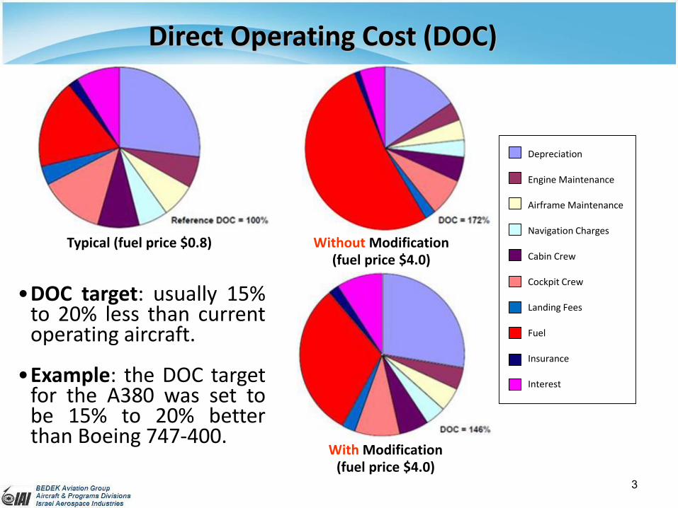
Direct Operating Cost (DOC)
Typical (fuel price $0.8) Without Modification(fuel price $4.0)
With Modification(fuel price $4.0)
•DOC target: usually 15%to 20% less than currentoperating aircraft.
•Example: the DOC targetfor the A380 was set tobe 15% to 20% betterthan Boeing 747-400.
Depreciation
Engine Maintenance
Airframe Maintenance
Navigation Charges
Cabin Crew
Cockpit Crew
Landing Fees
Fuel
Insurance
Interest
4
Advisory Council for AeronauticalResearch in Europe (ACARE)
Objectives 2020/2050• Noise reduction by 50%. • Fuel consumption and CO2 emission reduction by 50%. • NOx emissions reduction by 80%.
Engine Contribution • Noise reduction by 6 dB per operating point. • Specific fuel consumption (SFC) Reduction by 15% to 20%.• NOx emission Reduction by 60% to 80%.
/thpX H L D Use of carbon fibre reinforcedpolymer (CFRP) leads to significantreduction of the A350 XWBfuselage weight.
• H = Fuel heating value• Hηthp = V/SFC• L/D = Lift over drag ratio• R = Range• V = Aircraft Velocity
Bréguet Range Equations
max1 ln initial
final
WVLRangeSFC D W
initial E P FW W W W final E PW W W
6
Lift Over Drag Ratio (L/D)
Differentiating D/L for CL and equaling to zero, getting (D/L)min
At point A the lift-to-drag ratio is maximum:
• CL = Lift coefficient
• CD = Drag coefficient
• CD0 = Zero-lift drag
coefficient = SD0/S
• SD0 = Surface zero-lift drag
coefficient (∑CD0)
• k = Induced drag factor (or 1/e)• e = Oswald efficiency• D = Drag• L = Lift = W • W = Weight• S = Surface area • AR = Aspect ratio = b2/S• b = Span
AR
CkCC L
DD
2
0
k
ARCC
ARk
C
C
AR
Ck
C
C
dCd
D
L
L
DL
L
D
L
0
00 01
2
0
0
02 D
D
DD CARk
CARkCC
0max 4kSD
bD
L
AR
Ck
C
C
C
C
L
D L
L
D
L
D
0
0
0
0
maxmin
1 1
/D
D
D
LD D L C AR
C kkARC AR
k
7
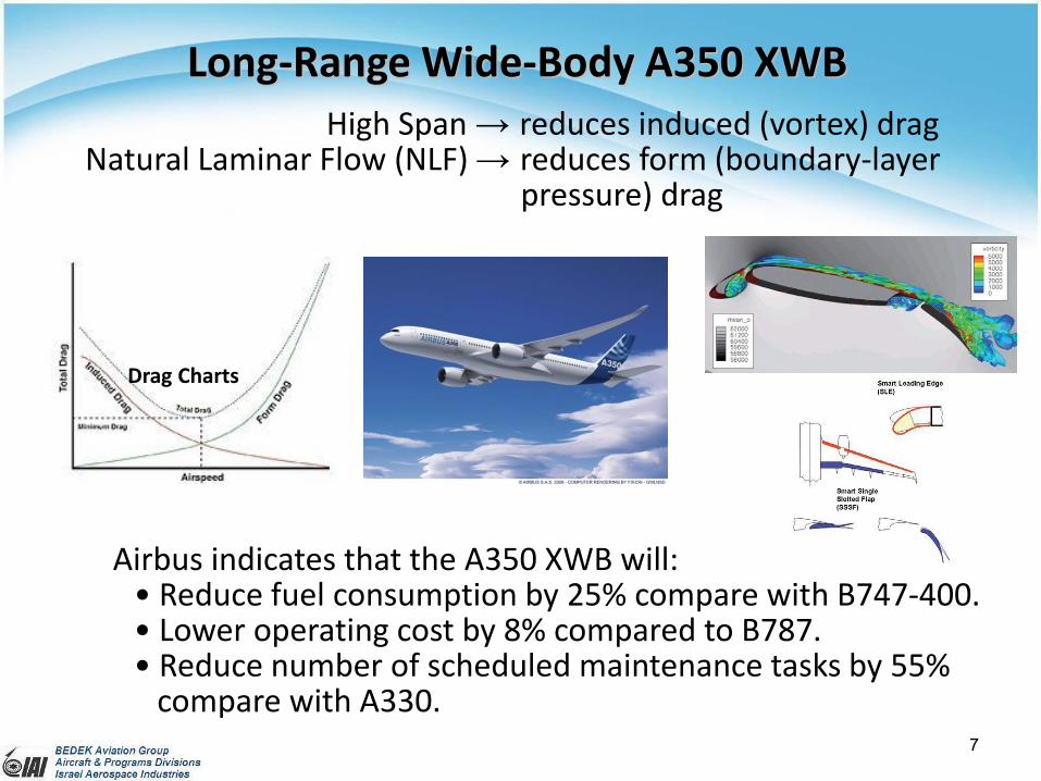
Airbus indicates that the A350 XWB will:• Reduce fuel consumption by 25% compare with B747-400.• Lower operating cost by 8% compared to B787.• Reduce number of scheduled maintenance tasks by 55%
compare with A330.
Long-Range Wide-Body A350 XWB
High Span → reduces induced (vortex) drag Natural Laminar Flow (NLF) → reduces form (boundary-layer
• CFM LEAP-X and P&W PurePower PW1100G engines are ready for near-term adoption by airframe manufacturers.
• These engines promise approximately 15% fuel-burn improvements overtheir predecessors in addition to 50% less maintenance hour (MH) over12 years.
• The A320neo is a retrofit option. The A320neo versions will have over95% airframe commonality with the 320ceo (current engine option)versions, enabling it to fit seamlessly into existing A320 Family fleets.
• The 737 MAX is not a retrofit option. It is a new airplane.
There is a size limit for high BPRturbofan in conventional airplanes
9
CFM LEAP-X
• Twin annular premixing swirlers (TAPS)increase oxygen in the combustor.
• Thrust range 18,000 to 35,000 lbf.• Bypass ratio (BPR) of 10 - 11 versus 6
on the CFM 56.• Utilize technology from the GEnx
engine developed for the B787/B747-8.• Extensive carbon fiber development.• 18 fan blades rather than 24 on the
CFM 56.
P&W PurePower PW1100G
• Fan geared configuration allow the fantips to operate in sub-sonic conditions.
• Thrust range 24,000 to 33,000 lbf.• Bypass ratio (BPR) of 12.
Narrow-Body Aircraft Re-Engine (cont.)
Fuel Consumption Improvement vs. Bypass Ratio (BPR)
10
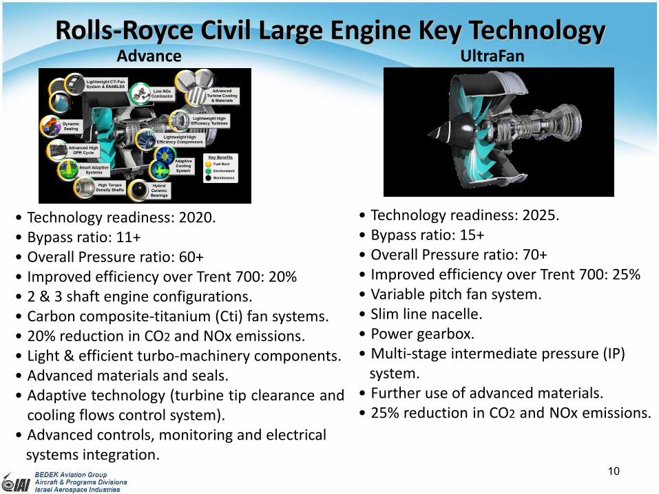
Rolls-Royce Civil Large Engine Key Technology
• Technology readiness: 2020.• Bypass ratio: 11+• Overall Pressure ratio: 60+• Improved efficiency over Trent 700: 20%• 2 & 3 shaft engine configurations.• Carbon composite-titanium (Cti) fan systems.• 20% reduction in CO2 and NOx emissions.• Light & efficient turbo-machinery components.• Advanced materials and seals.• Adaptive technology (turbine tip clearance and
cooling flows control system).• Advanced controls, monitoring and electrical
systems integration.
Advance UltraFan
• Technology readiness: 2025.• Bypass ratio: 15+• Overall Pressure ratio: 70+• Improved efficiency over Trent 700: 25%• Variable pitch fan system.• Slim line nacelle.• Power gearbox.• Multi-stage intermediate pressure (IP)
system.• Further use of advanced materials.• 25% reduction in CO2 and NOx emissions.
11
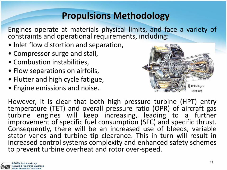
Engines operate at materials physical limits, and face a variety ofconstraints and operational requirements, including:• Inlet flow distortion and separation,• Compressor surge and stall,• Combustion instabilities,• Flow separations on airfoils,• Flutter and high cycle fatigue,• Engine emissions and noise.
However, it is clear that both high pressure turbine (HPT) entrytemperature (TET) and overall pressure ratio (OPR) of aircraft gasturbine engines will keep increasing, leading to a furtherimprovement of specific fuel consumption (SFC) and specific thrust.Consequently, there will be an increased use of bleeds, variablestator vanes and turbine tip clearance. This in turn will result inincreased control systems complexity and enhanced safety schemesto prevent turbine overheat and rotor over-speed.
Propulsions Methodology
Variation of SFC with OPR & TET
12
Thermal efficiency is improved byincreasing OPR & TET. Traditionally, this hasbeen achieved by new materials, improvedturbine cooling and smaller, high-speedcores.
However, at current technology level,where cooling flow increases with OPR &TET, and component efficiency deterioratesas engine cores become smaller, SFC gainsmay not be achieved from further OPR &TET increases.
Improvements in propulsive efficiency ariselargely through increases in bypass ratio(BPR) partly due to the OPR & TET increase.
Propulsions Methodology (cont.)
Thermal efficiency vs. OPR & TET
13
Aircraft Gas Turbine Engine Environment
Sensors and actuators have to operate reliably underextreme gas path pressure and temperature conditions
Active Control Potential
14
The More Electric Aircraft (MEA)
Electric wing ice protectionElectric environmental control system (ECS)Electric engine starting systemElectric power distribution and management systems (power on demand)Electro-mechanical actuators (EMAs), electro-hydrostatic actuators (EHAs) / electrical backup hydraulic actuators (EBHAs)Electric nitrogen-generation-system compressor used for fuel-tank inerting
More Electric Aircraft Conventional Aircraft
Unclassified15
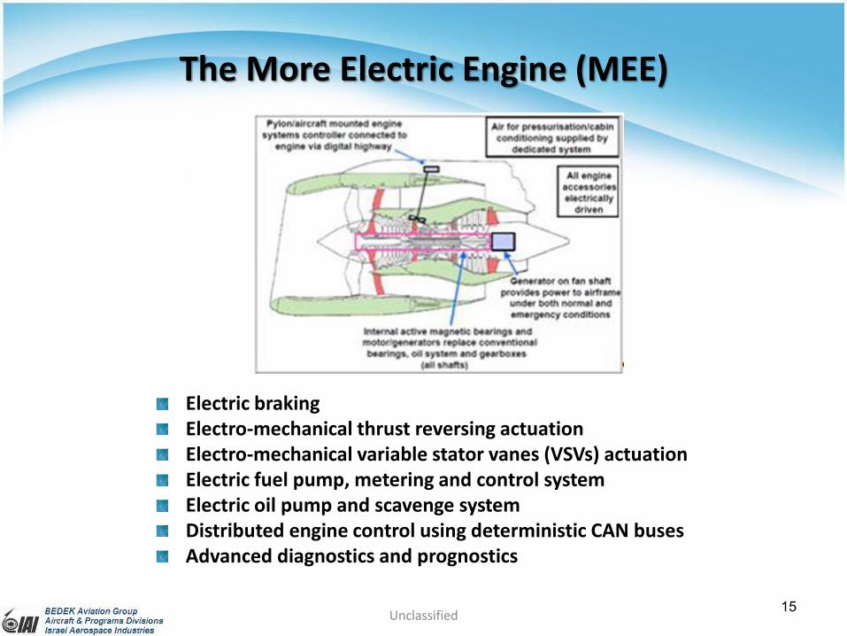
The More Electric Engine (MEE)
Electric brakingElectro-mechanical thrust reversing actuationElectro-mechanical variable stator vanes (VSVs) actuationElectric fuel pump, metering and control systemElectric oil pump and scavenge systemDistributed engine control using deterministic CAN busesAdvanced diagnostics and prognostics
16
Centralized and DistributedEngine Control Systems
Current Centralized Engine Control Architecture
Distributed Engine Control Architecture Future Extended Distributed EngineControl Architecture
17
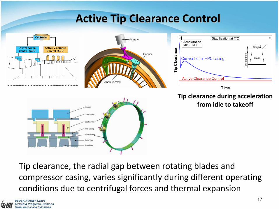
Active Tip Clearance Control
Tip clearance during accelerationfrom idle to takeoff
Tip clearance, the radial gap between rotating blades andcompressor casing, varies significantly during different operatingconditions due to centrifugal forces and thermal expansion
18
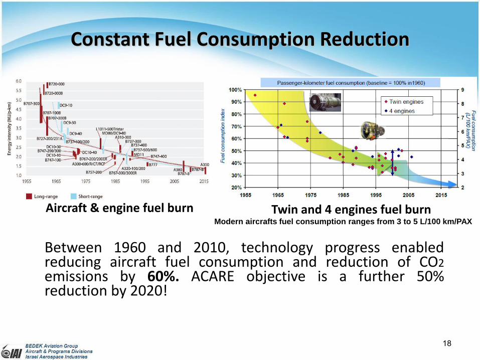
Between 1960 and 2010, technology progress enabledreducing aircraft fuel consumption and reduction of CO2emissions by 60%. ACARE objective is a further 50%reduction by 2020!
Constant Fuel Consumption Reduction
Aircraft & engine fuel burn Twin and 4 engines fuel burn Modern aircrafts fuel consumption ranges from 3 to 5 L/100 km/PAX
19
Constant NOx Pollutants and Noise Reduction
Noise ground footprint divided by 790% reduction in neighborhood impact
20
Engine Reliability
Over the last 25 years, engine reliability as measured in terms ofin-flight shutdown (IFSD) rate, has improved by more than tenfold,mainly due to the increased maturity of electronic engine controls(EECs) and enhanced testing procedures during the developmentphase.
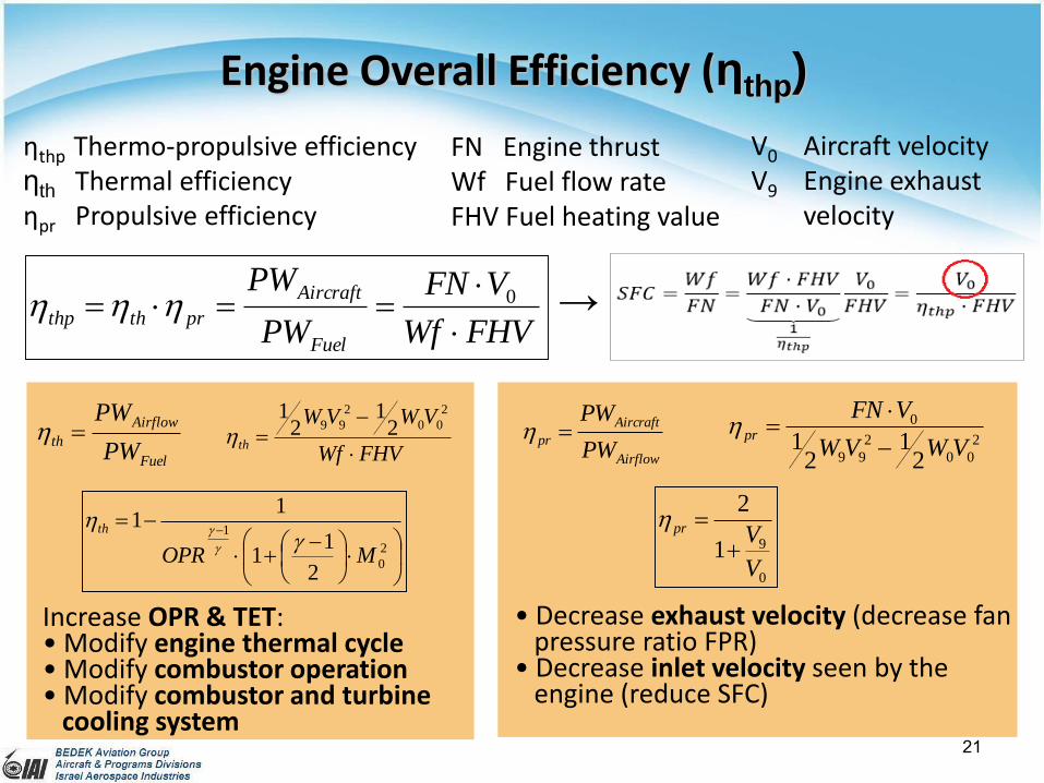
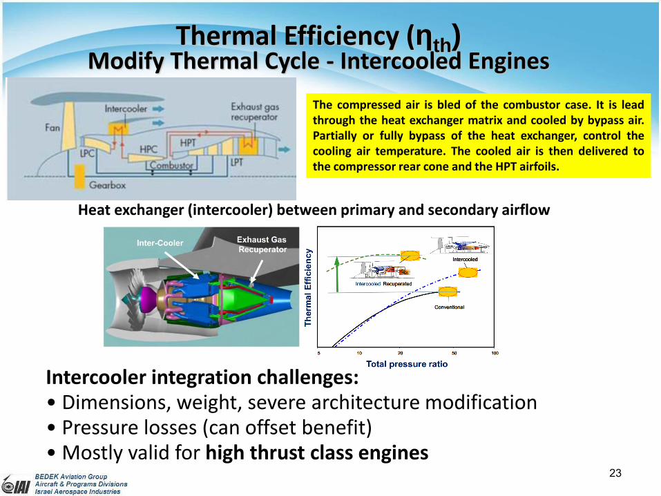
Intercooler integration challenges: • Dimensions, weight, severe architecture modification • Pressure losses (can offset benefit)• Mostly valid for high thrust class engines
Heat exchanger (intercooler) between primary and secondary airflow
The compressed air is bled of the combustor case. It is leadthrough the heat exchanger matrix and cooled by bypass air.Partially or fully bypass of the heat exchanger, control thecooling air temperature. The cooled air is then delivered tothe compressor rear cone and the HPT airfoils.
24
Compression air cooling,at constant pressure
3
3
Resize at constant T3 vs nominal engineOPR benefit → reduction fuel
consumption
Resize at constant P3 vs nominal engineT3 benefit → lower NOx emissions
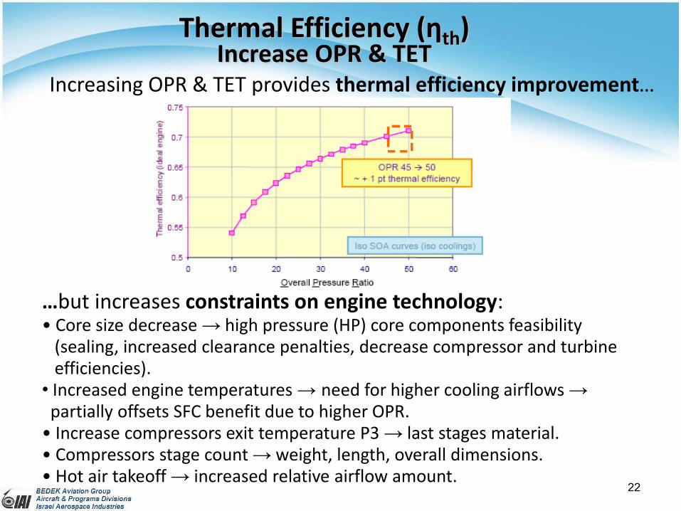
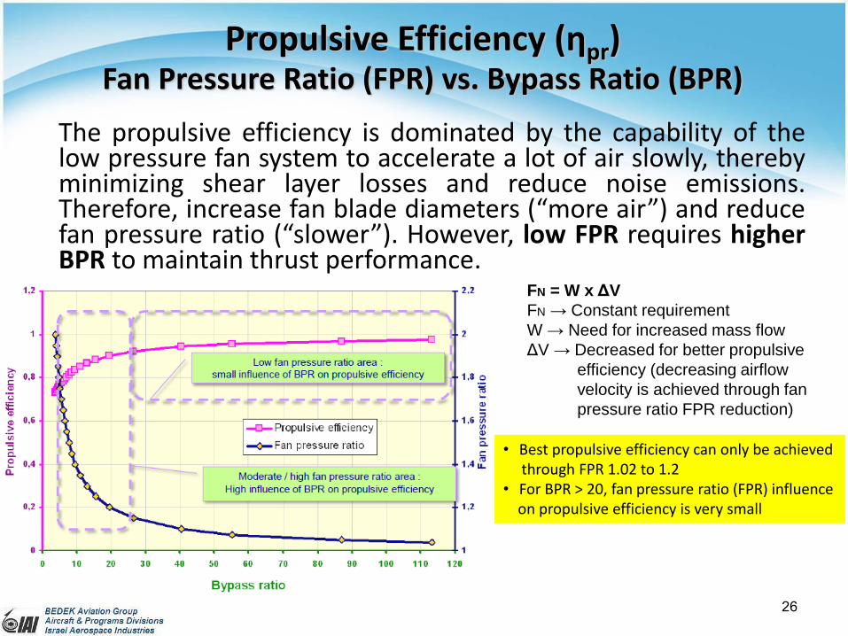
Propulsive Efficiency (ηpr)Fan Pressure Ratio (FPR) vs. Bypass Ratio (BPR)
The propulsive efficiency is dominated by the capability of thelow pressure fan system to accelerate a lot of air slowly, therebyminimizing shear layer losses and reduce noise emissions.Therefore, increase fan blade diameters (“more air”) and reducefan pressure ratio (“slower”). However, low FPR requires higherBPR to maintain thrust performance.
• Best propulsive efficiency can only be achievedthrough FPR 1.02 to 1.2
• For BPR > 20, fan pressure ratio (FPR) influenceon propulsive efficiency is very small
FN = W x ΔV
FN → Constant requirement
W → Need for increased mass flow
ΔV → Decreased for better propulsive
efficiency (decreasing airflow
velocity is achieved through fan
pressure ratio FPR reduction)
27
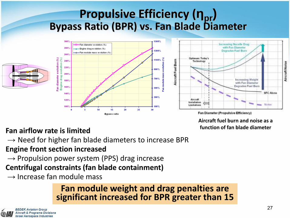
Propulsive Efficiency (ηpr)Bypass Ratio (BPR) vs. Fan Blade Diameter
Fan airflow rate is limited→ Need for higher fan blade diameters to increase BPREngine front section increased→ Propulsion power system (PPS) drag increaseCentrifugal constraints (fan blade containment)→ Increase fan module mass
Fan module weight and drag penalties aresignificant increased for BPR greater than 15
Aircraft fuel burn and noise as afunction of fan blade diameter
28
(CD = CD0 + ĸCL2/πA)
Propulsive Efficiency (ηpr)Conventional Propeller vs. Counter Rotating (CR) Dual Propellers