A Virtual Reality Training Tool for Upper Limb Prostheses DIPLOMARBEIT zur Erlangung des akademischen Grades Diplom-Ingenieur im Rahmen des Studiums Medieninformatik eingereicht von Michael Bressler Matrikelnummer 0425576 an der Fakultät für Informatik der Technischen Universität Wien Betreuung: Privatdoz. Mag.rer.nat. Dr.techn. Hannes Kaufmann Wien, 29.09.2013 (Unterschrift Verfasser) (Unterschrift Betreuung) Technische Universität Wien A-1040 Wien Karlsplatz 13 Tel. +43-1-58801-0 www.tuwien.ac.at
Transcript
A Virtual Reality Training Tool forUpper Limb Prostheses
DIPLOMARBEIT
zur Erlangung des akademischen Grades
Diplom-Ingenieur
im Rahmen des Studiums
Medieninformatik
eingereicht von
Michael BresslerMatrikelnummer 0425576
an derFakultät für Informatik der Technischen Universität Wien
Betreuung: Privatdoz. Mag.rer.nat. Dr.techn. Hannes Kaufmann
Technische Universität WienA-1040 Wien � Karlsplatz 13 � Tel. +43-1-58801-0 � www.tuwien.ac.at
A Virtual Reality Training Tool forUpper Limb Prostheses
MASTER’S THESIS
submitted in partial fulfillment of the requirements for the degree of
Diplom-Ingenieur
in
Media Informatics
by
Michael BresslerRegistration Number 0425576
to the Faculty of Informaticsat the Vienna University of Technology
Advisor: Privatdoz. Mag.rer.nat. Dr.techn. Hannes Kaufmann
Vienna, 29.09.2013(Signature of Author) (Signature of Advisor)
Technische Universität WienA-1040 Wien � Karlsplatz 13 � Tel. +43-1-58801-0 � www.tuwien.ac.at
Erklärung zur Verfassung der Arbeit
Michael BresslerMarkgraf-Rüdiger Str 3, 1150 Wien
Hiermit erkläre ich, dass ich diese Arbeit selbständig verfasst habe, dass ich die verwendetenQuellen und Hilfsmittel vollständig angegeben habe und dass ich die Stellen der Arbeit -einschließlich Tabellen, Karten und Abbildungen -, die anderen Werken oder dem Internet imWortlaut oder dem Sinn nach entnommen sind, auf jeden Fall unter Angabe der Quelle alsEntlehnung kenntlich gemacht habe.
(Ort, Datum) (Unterschrift Verfasser)
i
Danksagung
Zunächst möchte ich mich bei der Firma Otto Bock, und hier vor allem bei Andrei Ninu, für dieZusammenarbeit bedanken, welche dieses Projekt erst ermöglich hat. Auch gilt mein Dank vorallem meinem Betreuer Hannes Kaufmann, der mich während des ganzen Projektes mit Rat undTat unterstützt hat.
Weiter möchte ich Cosima Prahm für die Mitarbeit bei diesem Projekt danken, so wieChristian Schönauer und Annette Mossel für die Hilfe und Unterstützung, die ich von ihnenbekommen habe.
Schließlich geht mein Dank an meine Familie und alle meine Freunde. Ihr habt alle meineLaunen ertragen, und mich in jeder Hinsicht motiviert und unterstützt!
iii
Abstract
The technology of electromyography has become very common in being used to control handprostheses. This technology allows the capture of controlling signals for a prosthesis byattaching electrodes to the skin, over skeletal muscles. However, before practicing with a realprosthesis, the patient has to await the healing process of the arm stump. Furthermore, thelearning process can be difficult and frustrating.
In this thesis, a training environment will be presented, capable of simulating the process ofgrasping virtual spheres with a virtual hand by using the proper amount of grip force. The virtualreality experience, is created by using the ioTracker motion tracking system, developed at theVienna University of Technology. This system is capable of tracking the motions of the headand arm of a protagonist with six degrees of freedom (position and orientation). The createdtracking data is forwarded through the OpenTracker framework into an application created withthe free version of the game engine Unity3D. In this application, the tracking data is translatedinto a virtual 3D environment and visualized. The picture created by the virtual camera, whichis mounted to the head of the protagonist, is transmitted wirelessly to a head mounted display(HMD) that the protagonist is wearing. This allows the protagonist to move around freely insidean area of 4x4 meters.
As this work was done in collaboration with Otto Bock, the same technology was used forcontrolling the virtual hand, as it is embedded in the Michelangelo Hand prosthesis by OttoBock. Using two electrodes, the electrical activity of skeletal muscles is measured through theskin and is further processed into controlling signals, which are then sent to the simulation.
As the goal of this work was both, to create an environment for exercising and to evaluatehand prostheses, the electromyographic (EMG) controlling signals can be mapped in a flexibleway to certain behaviors of the prosthesis. Furthermore, several simulation modes for creatinggrip force can be used, which again is indicated to the protagonist by several optical graspingaides. The virtual arm can be adjusted to best match the real circumstances. Finally, severaloptions are provided for creating and performing various evaluation and training scenarios.Based on the final application, several of these scenarios have been created and tested withprobands for evaluating the capabilities of the system.
v
Kurzfassung
Der Gebrauch von myoelektrischen Handprothesen ist inzwischen weit verbreitet. Mit dieserTechnologie ist es möglich, Steuersignale für die Prothese mittels Elektroden zu erfassen,welche direkt auf der Haut über Muskeln platziert werden. Allerdings muss der Betroffeneden Heilungsprozess der Amputation abwarten, bevor er damit anfangen kann, eine Prothesezu verwenden. Außerdem kann dieser Prozess vor allem am Anfang schwierig und frustrierendsein.
In dieser Arbeit wird eine Trainingsanwendung vorgestellt, welche es erlaubt, in einem virtu-ellen Raum mit einer Hand nach Kugeln zu greifen, wofür eine jeweils der Kugel enstprechendeGriffkraft aufgewendet werden muss. Um die virtuelle Realität zu erschaffen, in der sich diesesSzenario abspielt, wird das Tracking-System ioTracker verwendet, welches an der technischenUnversität Wien entwickelt wurde. Mit diesem System werden die Bewegungen von Kopf undArm des Akteurs in 6 Freiheitsgraden aufgezeichnet (Position und Orientierung) und mittels desOpenTracker Frameworks an eine weitere Anwendung übertragen, welche mit der freien Versionder Game Engine Unity3D entwickelt wurde. In dieser werden diese Bewegungsdaten mittelseiner dafür entwickelten Software in eine virtuelle 3D Umgebung übertragen und visualisiert.Das Bild der virtuellen Kamera, welche mit dem Kopf des Akteurs mitbewegt wird, wird drahtlosan ein am Kopf des Akteurs befestigtes Display (Head mounted display, HMD) übertragen. Diesermöglicht es dem Akteur, sich innerhalb eines begrenzten Bereiches von 4x4 Metern frei imRaum umherzubewegen.
Da diese Arbeit in Zusammenarbeit mit Otto Bock durchgeführt wurde, konnte für dieSteuerung der virtuellen Hand die gleiche Technologie verwendet werden, wie sie in der vonOtto Bock entwickelten Michelangelo Handprothese eingebaut ist. Mittels zweier Elektrodenwird die elektrische Aktivität von Muskeln unter der Haut gemessen und in Steuersignaleumgerechnet. Diese werden anschließend über eine drahtlose Verbindung an die Simulationgesendet.
Da das Ziel dieser Arbeit sowohl in einer Trainingsumgebung als auch in einer Testum-gebung für Handprothesen bestand, gibt es mehrere Möglichkeiten, die elektromyographischen(EMG) Steuersignale auf die virtuelle Hand anzuwenden. Weiters können diverse Simulationsar-ten für die Erzeugung von Griffkraft verwendet werden, welche wiederum dem Akteur währenddes Greifens durch optische Anzeigen signalisiert wird. Der virtuelle Arm kann angepasst wer-den, um die Simulation so gut wie möglich an die realen Gegebenheiten anzupassen. Schließlichwurden diverse Einstellungsmöglichkeiten implementiert, um das Erstellen und Durchführenvon unterschiedlichen Test- und Trainingsszenarion zu ermöglichen. Im Anschluss an die Arbeitwurden Übungs-Szenarien entwickelt und mit Personen durchgeführt, Um die Fähigkeiten des
vii
Systems zu testen, wurden im Anschluss an die Arbeit Übungs-Szenarien entwickelt und mitVersuchspersonen durchgeführt.
The work presented in this thesis was initiated by the Otto Bock company, a manufacturerof prostheses. In collaboration with the Vienna University of Technology, a virtual realityapplication should be developed. This virtual environment should be capable of simulating thegrasping action of the myoelectrical Michelangelo Hand prosthesis, developed by Otto Bock, bya virtual prosthesis in a virtual environment. Such an application could provide several benefitsregarding the evaluation of prostheses by experts as well as issues of supporting the rehabilitationprocess of upper-limb amputees.
Myoelectric hand prostheses, such as the Michelangelo Hand have been used for more than50 years, and since then this technology has improved steadily. Basically, such prostheses aredriven by controlling signals the amputee creates by contracting and relaxing muscles in his armstump. By using the same EMG technology, which is embedded in the Michelangelo Hand,for creating controlling signals which then are used by the virtual reality simulation it can beassured that the handling of the virtual myoelectric hand is similar to a real prosthesis.
As mentioned before, such an application could serve as an evaluation environment for handprostheses. For example, the evaluation of a certain control mode for a myoelectric prosthesiscan easily be performed without the need for programming the signal tracking hardware. Forthe same reason, it would also be possible to quickly adjust parameters or even try differentcontrol modes with flexibility that cannot be reached by a common prosthesis. The presenceof a graphical user interface provides control over complex parameters like the hand position,which probably could not be adjusted properly without such an aide.
Furthermore, since all the action takes place inside the application, it is possible to defineall parameters concerning the simulation exactly and to measure and capture every conceivableaspect of the simulated grasping action for later evaluation and analysis.
Alternatively, such an application could function as a virtual training environment for upper-limb or forearm amputees. Using computers for supporting rehabilitation issues provides allpossibilities involving such a multimedia-based in- and output platform. These possibilities
1
range from creating a visual and acoustic output up to a highly interactive 3D gaming scenario,as known from modern video games.
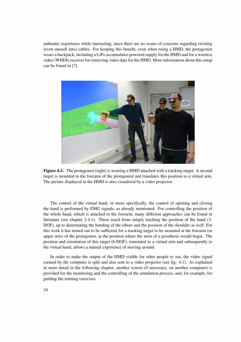
The use of virtual reality should thereby allow the protagonist to reach a high level ofimmersion while exercising. The system presented in this work allows the protagonist to weara head mounted display (HMD), visualizing the virtual environment. It is possible to look andmove around freely (in a limited area) and in a natural way, which does not require any additionallearning and allows the protagonist to concentrate on the interaction with the virtual hand.
After an amputation, the patient usually is not able to use a prosthesis immediately, sincethe arm stump has to heal first. Furthermore, a stem for the prosthesis has to be specificallymanufactured, as it has to perfectly fit the arm stump of the amputee. During this period, it wouldbe very useful for the amputee to have the possibility of exercising and preparing for the handlingof a prosthesis. In contrast to using a prosthesis stem, for capturing the necessary controllingsignals, it is usually sufficient to attach electrodes to the arm stump. Such an approach is donewithin minutes, and since much more flexibility is possible in regards to the healing process, thiscan be done much earlier than adapting a prosthesis stem.
In order to use myoelectric hand prostheses, an amputee first has to learn how to create theappropriate EMG signals. As mentioned before, this is done by respectively contracting andrelaxing the particular muscle. Especially in the beginning, the use of a virtual environment canprovide advantages for exercising. For example, by disabling the effect of gravity it is possibleto prevent objects from falling down, which could complicate the exercises.
Depending on the accident which resulted in the amputation, as well as on the developmentof the healing process of the arm stump, the degrees of freedom, with wich an amputee isable to control the prosthesis afterwards, differs from person to person. The capabilities of theamputee regarding these degrees of freedom when controling a prosthesis could be evaluated andimproved by such a system, without the need for a real prosthesis and therefore for a prosthesisstem as well.
Finally, the creation of serious game scenarios includes the possibility of creating highlyeffective exercising tasks, which are not only entertaining for the patient but also capable ofmaintaining the motivation to strive when exercising. This aspect certainly has a big influence onthe development of the rehabilitation process. In view of modern video games, the possibilitiesare given to provide a varied and challenging gaming, and thus, rehabilitation experience.
1.2 Problem Statement
The final application, as generally presented in this thesis, is the result of two consecutiveproblem specifications, which will be introduced in the following subsections.
The Primal Problem
The first specification, given by Otto Bock, was to create a non-specific virtual reality environ-ment, including a virtual prosthesis similar to the Michelangelo Hand as an interaction device,capable of grasping and moving objects.
2
A system for creating the virtual reality simulation itself already existed, therefore thedecision to make use of these technologies more ore less was given. This solution consistsof the ioTracker motion tracking system, developed at the Vienna University of Technology, formeasuring and capturing the movements of certain targets. This captured data then is transmittedthrough the OpenTracker framework, and finally sent to the game engine Unity3D for creatingand visualizing the virtual environment.
Thus, an application in Unity3D had to be developed, containing a virtual environment anda moveable model of a virtual hand, based on the Michelangelo Hand. As mentioned above,receiving tracking data of certain targets in Unity3D through the OpenTracker framework wasalready possible. These targets would be placed respectively at the protagonist’s head and arm,for moving a virtual camera and the virtual arm (respectively prosthesis stem), the virtual handis attached to.
Since the Michelangelo Hand prosthesis uses a myoelectric controlling system, the sametechnology was used for supplying the simulation with controlling signals for the virtual hand.In order to receive these signals from the tracking hardware device provided by Otto Bock, itwas necessary to extend the OpenTracker framework by an interface to this hardware, since theinterface between the OpenTracker framework and Unity3D already existed.
For mapping the received controlling signals to a certain behavior of the prosthesis, nospecifications were given. In view of a highly flexible evaluation environment, an attemptwas made to design a mapping system which is capable of fulfilling such requirements, as,for example, defining certain hand positions, which can be triggered by the protagonist of thesimulation. As the interaction of grasping virtual objects should be as realistic as possible, thegoal was to use the built-in physics engine of Unity3D to create realistic behavior of particularobjects when being grasped. Designing the environment, as no specifications were given, wasdone with the idea of a serious game scenario.
A More Specific Prototype
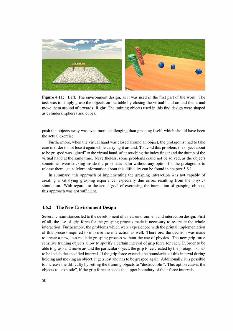
Based on this first part of the work, a more specific secondary problem statement was given. Themain focus of the second specification was the simulation of grip force for evaluating feedbackdevices regarding this issue. Additionally, a new design for the environment, including thetraining objects, was given and these training object were extended by the property of onlybeing graspable with a certain amount of grip force.
For providing this new grasping interaction, and due to problems regarding the physicsengine powered grasping process, the whole interaction process was redesigned. Additionally,for supporting the protagonist in the virtual environment in creating the right amount of gripforce when grasping an object, optical indicators had to be created.
Furthermore, the connection to the electromyographic tracking device for receiving control-ling signals for the virtual hand had to be extended to provide bidirectional communication.Therefore these additional methods had to be implemented in the OpenTracker interface forthe tracking device. Additionally, the adopted OpenTracker interface to Unity3D had to beextended by this functionality as well. In the virtual reality application itself, the functionalitywas implemented to send configuration commands to the tracking device.
3
Finally, in this second part, the concept of training scenarios was introduced in order toprepare and perform exercises. Additionally, for providing the possibility to perform varioustests, primarily for evaluating the use of grip force feedback devices, several parametersregarding the new grasping interaction were designed.
1.3 Limitations of the Thesis
The problem of tracking human motions as performed by the ioTracker system will be intro-duced in the following chapter 2.2, but since this tracking system is no part of the implementationof this thesis, the technical problem of tracking itself will not be treated.
For controlling the virtual hand, the technology of electromyographie (EMG) is used forcreating the relative signals. The main difficulty of this issue consists of recognizing therecorded EMG signal and creating the appropriate controlling signal, which basically is a patternrecognition issue. This task is performed by the EMG tracking device provided by Otto Bock,and will not be further treated in this thesis.
At the end of the practical work, tests were performed with four healthy people as well aswith four forearm amputees. The purpose of these tests was mainly to evaluate the usabilityof the simulation and the practicality of the various test scenarios. However, no (meaningful)studies have yet been performed with this application.
1.4 Chapter Overview
This thesis is separated into seven chapters. In this chapter, the problem statements regardingthe thesis were given. In the second chapter, similar research is presented, and an introductioninto the main issues regarding the design and technical implementation of such an application isgiven. The third chapter introduces the technologies, which this thesis is based on.
In the fourth chapter, the design of the grasping interaction and of the environment ispresented as well as the hardware setup for the virtual reality simulation and the scope offunctionalities and settings for controlling the progress of the simulation. In the fifth chapter,the implementation of the Unity3d application as well as of the extensions for the OpenTrackerframework are presented.
The sixth chapter presents the results of user-tests, performed at the end of the practicalwork and discusses difficulties in the implementation process as well as the usability of theenvironment and interaction design, also with regards to the user-tests performed. Finally, in theseventh chapter a summary of the thesis is given, and further goals and application possibilities,based on the insights and solutions gained during the process of the practical work, will bepresented.
4
CHAPTER 2Related Work
2.1 Introduction
In this chapter, an overview of related works and approaches as found in literature will be given,on the one hand related to this work due to the technologies used, on the other hand relateddue to similar approaches of creating a virtual training or evaluation environment for upper limbprostheses.
The important technologies used in this work can roughly be broken down into humanmotion tracking and controlling prostheses with electromyographical (EMG) signals. Theseproblems are respectively treated in the first two subchapters. The use of these technologiesstrongly influences the design of the resulting interaction interface, the level of immersion andfinally the boundaries for creating an interactive virtual environment. This issue of interactioninterfaces, as well as the continuative issue of serious games, will be treated in the thirdsubchapter, both in the context of computer supported rehabilitation.
Finally, in the fourth subchapter, works with a similar approach of creating a virtual training-and evaluation environment for upper limb prostheses will be presented and compared to therequirements of this work.
2.2 Human Motion Tracking
One approach for creating an interaction interface for a virtual reality application is to directlyuse the motions of parts of a human body and translate them into the virtual environment.
For tracking human motions, a huge range of technologies has been developed, using a widerange of different technical solutions. A general classification of these tracking technologies isgiven in [31] (fig. 2.1). As illustrated in this figure, another subdivision is done into visual andnon-visual technologies. Searching in literature for recent works with the similar goal of track-ing human motions in the domain of computer-assisted rehabilitation predominantly returnedapproaches using visual tracking technologies, again in a large variety of implementations.
5
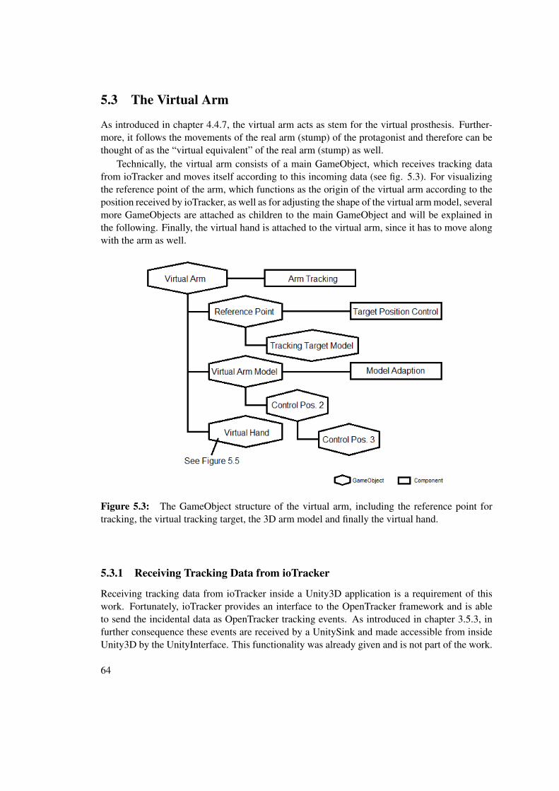
Figure 2.1: A general classification of human motion tracking technologies given by [31].
System Accuracy Costs DrawbacksInertial High Low DriftsMagnetic Medium Low Ferromagnetic materialsUltrasound Medium Low OcclusionGlove High Medium Partial postureMarker High Medium OcclusionMarker-Free High Low OcclusionCombinatorial High High MultidisciplinaryRobot High High Limited motion
Table 2.1: Performance comparison of different motion tracking systems according to fig. 2.1( [31], in condensed form).
Due to the rising capability of real time video recording and processing, especially in thedomain of smart phones, the costs for this type of technology is getting lower and the field ofpossible applications is getting bigger. Visual tracking therefore seems to be the most recentState-Of-The-Art technology and since this work also uses a marker-based visual trackingsystem, the focus in the following will be on visual tracking solutions.
A proper low-cost visual solution without using markers is the Microsoft Kinect sensor,which provides a real-time recognition and tracking of up to two protagonists. In [16] such askeletal tracking solution is presented. This technology is not expensive and even sufficientlyaccurate for moving a virtual prosthesis around in a simple training environment, but theinteraction method is more suitable for a visual output on a screen or television than on a headmounted display as used in this work, since the head motions are not translated to the virtualenvironment. Nevertheless, for rehabilitation issues as well as for virtually evaluating prosthesessuch an approach might be sufficient.
Another interesting visual approach for tracking human motions without using markers ispresented in [24]. Cameras are placed on certain points of the protagonist’s body and theircaptured material is later used for calculating a three-dimensional skeleton model (see fig. 2.2).This technology was developed for motion capturing with the goal of character animation and is
6
not suitable for this work, at least because of the expensive nature of implementing wireless real-time measurement for all the cameras. However, by comparing this and the previous technology,another interesting criteria for visual tracking systems can be introduced.
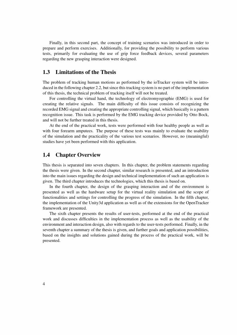
Figure 2.2: Left: The protagonist is wearing body-mounted cameras for motion capturing [24].Right: A overhead-mounted Wii Remote control is tracking the positions of the protagonist’shead and of the hand-held second Wii Remote control. The joystick of this second control isused for spatial navigation [5].
While the second solution requires the protagonist to be equipped with cameras, which afterbeing placed need to be calibrated, the Kinect sensor needs no additional equipment and theprotagonist can start interacting without any preparations, which - in relation to rehabilitationapplications - can be displeasing for the protagonist. Furthermore, the personal moving space isnot limited (even not mentally) when not wearing any equipment.
A setup better fitted to the requirements of this work is presented in [5]. This approachuses two Wii Remote controls. One is held by the user and moved around as virtual inputdevice (additionally, the joystick of the Wii Remote is used for spatial navigation in the virtualenvironment), while the other control is fixed above the head of the protagonist and used fortracking the positions of the head and the handheld-control. For tracking, the infrared sensor ofthe Wii Remote is used, and clusters of infrared lights are mounted on the protagonist’s head aswell as on the hand-held Wii Remote (see fig. 2.2).
7
Since this technology can be classified as marker-based visual tracking, and as the solutionused in this work falls into the same category, a closer overview of works using this technologywill be given in the following subchapter.
2.2.1 Marker-Based Visual Tracking
Since the goal of this work was to create a realistic simulation of controlling a prosthesis, thedecision was made to achieve this goal by using the technology of electromyography (see chapter2.3 for an introduction). For controlling a virtual hand by using a healthy hand, an approach ispresented to track the movements of the hand by using a colored glove [30] (see fig. 2.3). Thissolution is interesting insofar as the use of colored labels could also be extended to the wholebody and be used for tracking the head’s position as well. This is important for the virtual HMDexperience.
Figure 2.3: A colored glove is tracked by a camera for controlling a virtual hand [30].
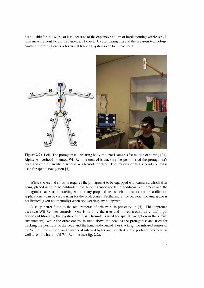
Following this last idea of tracking the whole body, a similar approach is presented in [6].This system again uses infrared LEDs, but unlike to the Wii Remote setup, the LEDs aremounted to the camera instead of the protagonist. The protagonist on the other hand wearsfive infrared-reflective markers (ankles, wrists and belly). Since a marker would be occludedeasily when only one camera is monitoring the scenery, four cameras are placed in a way thatthey monitor a certain area in which the protagonist can move around. This technology is closeto the ioTracker system used in this work.
Using the tracking system as presented in [6] allows the tracking of position of certain pointsof interest, such as the ankles, wrists and the belly of a protagonist. This allows the creation of arough 3D skeleton model, with the level of detail of this model can easily be increased by addingadditional markers (e.g. elbows, knees). For each marker, the position in space can be calculatedfor all three axes, which is consistent with three degrees of freedom (3-DOF). But for creatinga virtual HMD experience, it is necessary to track the heads position as well as its orientation,which extends the required degrees of freedom to six (6-DOF).
This can be achieved by tracking several points for each marker. While one point per markerallows 3-DOF, with two points 5-DOF and with at least three points 6-DOF are possible totrack [8] (see fig. 2.4). Similar to this approach, the ioTracker system used in this work uses
8
Figure 2.4: Left: POSTRACK protagonist wearing five retro-reflective markers [6]. Right:Tracking one, two ore three points provides information of three, five or six degrees of freedom[8].
multiple-point clouds per marker for achieving 6-DOF tracking per marker. An introduction tothe ioTracker system can be found in chapter 3.2.
2.3 Electromyography (EMG)
As mentioned in the first chapter, one goal of this work was to create a prosthesis control, whichis as realistic as possible. This was done by using hardware developed by Otto Bock and used intheir prostheses. This hardware makes use of the electromyography (EMG) technology, whichwill be introduced in the following.
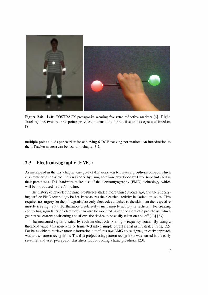
The history of myoelectric hand prostheses started more than 50 years ago, and the underly-ing surface EMG technology basically measures the electrical activity in skeletal muscles. Thisrequires no surgery for the protagonist but only electrodes attached to the skin over the respectivemuscle (see fig. 2.5). Furthermore a relatively small muscle activity is sufficient for creatingcontrolling signals. Such electrodes can also be mounted inside the stem of a prosthesis, whichguarantees correct positioning and allows the device to be easily taken on and off [13] [23].
The measured signal created by such an electrode is a high-frequency noise. By using athreshold value, this noise can be translated into a simple on/off signal as illustrated in fig. 2.5.For being able to retrieve more information out of this raw EMG noise signal, an early approachwas to use pattern recognition. The first project using pattern recognition was started in the earlyseventies and used perceptron classifiers for controlling a hand prosthesis [23].
9
Figure 2.5: Left: EMG electrodes attached to the lower arm [23]. Right: A recorded EMGsignal (top) and the corresponding control command generated by a threshold (bottom) [13].
A more recent approach of pattern recognition is presented in [22]. In this project 16electrodes are attached to the skin of the forearm1. This setup aims to reduce the noise in therecorded signal to a minimum. For feature extraction, the signal is separated into its underlyingbasic frequencies. Classification is done by collecting these frequencies together into a featurevector and compare them to a database with already classified feature vectors. Another algorithmfor classifying EMG signals is presented in [13] and is based on a neural network in combinationwith an auto-regressive based algorithm for feature extraction, in order to keep the neededprocessing power low.
More examples for the use of EMG technology in rehabilitation and prosthetics are givenin [25], where a EMG controlled voice prosthesis is presented which uses pattern recognitionfor classifying the recorded signals as single words. For post-stroke hand rehabilitation, a EMG-driven hand robot is presented in [14]. This robot is steered by two EMG electrodes, which areattached to the forearm. The electrode for opening the hand is located on the extensor digitorum(ED) muscle, which is usually used for extending parts of the hand. For closing the hand, thesecond electrode is located on the abductor pollicis brevis (APB) muscle, which is used, forexample, when grasping.
Such a controlling system consisting of two electrodes is similar to the one used in thiswork. The use of only two electrodes limits the degrees of freedom for controlling the prosthesis.However, when measuring more than two signals, things soon start to get complicated. If theelectrodes are located too close, it is not possible to detect the proper muscle activity with therespective electrode. As experienced during this work, this can even be a problem when usingonly two electrodes. Another issue is the ease of learning for the user. Concerning amputees,among other criteria it depends on the shape of the prosthesis stem, as resulting from the neededsurgeries, and also on the age of person involved, how many degrees of freedom can be handled
1Additionally to the 16 surface EMG electrodes, six needle electrodes are attached
10
by the user. Finally, opening and closing the hand prosthesis seems to be sufficient for fulfillingmost of the essential daily actions and restore independence and quality of life for the amputee,which is another important criterion for finding the right balance between easy usability andsufficient flexibility.
2.3.1 Control of a Virtual Hand
In contrast to controlling the virtual hand with visual tracking technologies, such as a coloredglove [30], in the work presented in [10], not only the movement of the virtual hand itself aretracked by EMG signals. Supported by accelerometers, the EMG signals are classified intoseveral kinds of hand motions and arm positions, and therefore also allow to approximatelytrack the position of the arm.
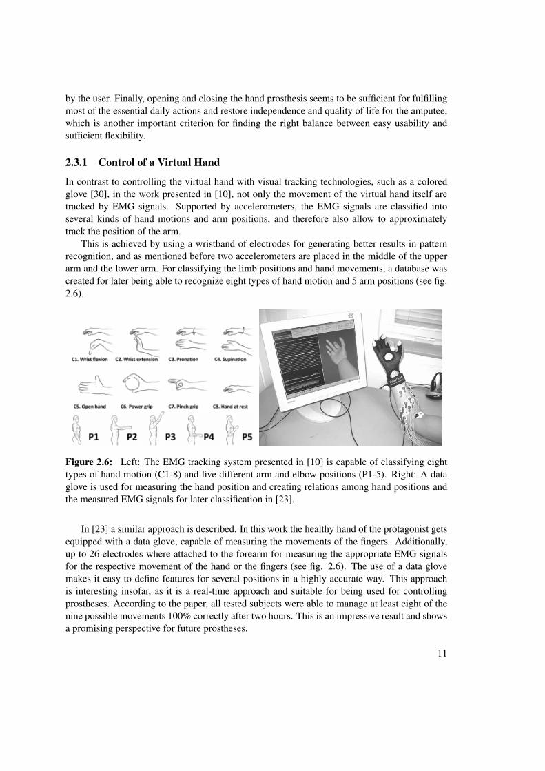
This is achieved by using a wristband of electrodes for generating better results in patternrecognition, and as mentioned before two accelerometers are placed in the middle of the upperarm and the lower arm. For classifying the limb positions and hand movements, a database wascreated for later being able to recognize eight types of hand motion and 5 arm positions (see fig.2.6).
Figure 2.6: Left: The EMG tracking system presented in [10] is capable of classifying eighttypes of hand motion (C1-8) and five different arm and elbow positions (P1-5). Right: A dataglove is used for measuring the hand position and creating relations among hand positions andthe measured EMG signals for later classification in [23].
In [23] a similar approach is described. In this work the healthy hand of the protagonist getsequipped with a data glove, capable of measuring the movements of the fingers. Additionally,up to 26 electrodes where attached to the forearm for measuring the appropriate EMG signalsfor the respective movement of the hand or the fingers (see fig. 2.6). The use of a data glovemakes it easy to define features for several positions in a highly accurate way. This approachis interesting insofar, as it is a real-time approach and suitable for being used for controllingprostheses. According to the paper, all tested subjects were able to manage at least eight of thenine possible movements 100% correctly after two hours. This is an impressive result and showsa promising perspective for future prostheses.
11
2.4 Computer-Assisted Rehabilitation
As the domain of computer-assisted rehabilitation is huge, the overview of related papers givenin this section will be limited to upper limb rehabilitation applications. The most interestingaspect of such a rehabilitation system probably is the design of the interaction interface, asthis determines the kind of exercises which can be performed. Furthermore, limiting the worksmakes it possible to compare the particular interfaces presented, as the requirements for creatingupper limb rehabilitation environments basically include the control of a virtual hand and/orarm1. This issue will be treated in the first subsection.
The effectiveness of a rehabilitation program obviously can be increased by raising the levelof active participation of the patient. Especially for elderly patients the motivation to eagerlyperform an exercise can be improved by providing interesting and entertaining training exercises[9]. Based on the interface, which in large part specifies the level of immersion that can beaccomplished by the user, this is another interesting aspect of computer-assisted rehabilitation,as the use of computers makes it easy to create quite complex multimedia-based interactivescenarios. An overview of serious games regarding upper limb rehabilitation will be given inthe second subsection.
2.4.1 Interaction Interfaces
The use of computers for rehabilitation does not only give access to a multimedia-basedplatform, it also opens the door for the use of telecommunication. This enhances the levelof convenience for patients with reduced mobility, while it also enables autonomous exercisingand allows a more efficient coaching of patients by the clinic.
Figure 2.7: A system for telerehabilitation as presented in [2].
1 The most interfaces which are considered for being used with a healthy hand, can also been thought of asclosing and opening of the virtual hand is being controlled by the use of EMG electrodes attached to an arm stump.
12
This approach was presented in 2000, therefore the technology used for the interface is notstate-of-the art. Nevertheless, it is interesting to have a closer look at it. The user wears a glovefor tracking the motion of the fingers. A receptor for a magnetic tracking system is attached tothe wrist of the user in order to track the position of the hand. For voice commands, a microphonearray, connected to a voice recognition software running in the background, is placed on top ofthe screen. Finally, a camera is installed with patient as well as in the clinic for video telephony(see fig. 2.7) [2]. This interface, if slightly modified, basically would also fit the needs of thiswork, and the concept of telerehabilitation is promising.
Another kind of interaction interface, which is rather present in works for upper limbrehabilitation, is the use of a robot arm, as presented in the rehabilitation system PLEMO [17](see fig. 2.8). Basically, the benefits of such a system in contrast to a visual tracking system arethe lower costs of calculation power needed for the process of tracking. However, for controllingthe position of a virtual arm and hand, such a system might limit the free moving space ofthe patient too much, resulting in the danger that the exercises performed are too grindingand onesided. Furthermore, because the accuracy of visual tracking systems is increasing, thebenefits of using robot arms as the less complex technical solution, is disappearing.
Figure 2.8: Left: PLEMO Rehabilitation System for Upper Limbs. The patient has to movethe grip over the working table, according to the task, given on the screen [17]. Right: The useris wearing a HMD and a glove for interacting with a virtual environment [20].
An interaction interface close to the one used in this work is presented in [20]. The patientwears a HMD display and a glove. The positions of the head and the glove are tracked andenable the patient to look around in a 3D environment and use the hand as interaction device(see fig. 2.8). Additionally, the glove measures the position of the fingers for controlling thevirtual hand. This interface setup provides a high level of immersion due to the HMD and the
13
intuitive control of the virtual arm and hand, and is therefore a good foundation for creatingexciting and entertaining rehabilitation exercises.
2.4.2 Serious Games
As mentioned in the beginning of this subchapter, the use of games for rehabilitation issues hasclearly proven its ability to increase the patient’s motivation during exercising. While creatingstimulating games for elderly people is a greater challenge, for children such a virtual interactivegaming environment can be satisfying over a longer period of time [11] [9].
An important factor for creating a satisfying gaming experience is the use of scoringmechanisms. These not only allow to monitor the progress of the rehabilitation process, butalso give the user the possibility to find a challenge in breaking a new high-score. And finally, ascoring system makes it easy to create a meaningful game, which also is an important factor formotivation [3]. Especially at the beginning of the rehabilitation process, the experience of failingcan be quite frequent for the patient. To avoid this, games can be designed in a way that theyadapt the level of difficulty to the skills of the player [4]. This is a very common approach in thedomain of entertainment games, since it is usually necessary to introduce a player to the gamingprocess at the beginning. By, for example, separating the process of playing into several stagesand respective levels, a straight and comprehensive path during the game and the rehabilitationprocess can be created for the patient. In figure 2.9, two examples for upper limb rehabilitationgames are illustrated.
Figure 2.9: Two examples for serious games used for upper limb rehabilitation. Left: Whacka mouse game, Right: Catching oranges game, both presented in [3].
The exercises themselves, seen from the perspective of rehabilitation, can also be dividedinto several different gaming tasks for keeping the patient’s motivation up. Therefore, exercisinga grasping process could start with catching a mouse on a table, while the next level in difficultycould be grabbing oranges from a tree, which requires the patient to stand straight and move thearm as well. A third level of difficulty could be the catching of some sort of moving objects.As long as playing the game creates satisfaction for the patient, it will support the rehabilitation
14
process. Scenarios as illustrated in figure 2.9 are neither costly to the hardware needed forvisualization, nor does their creation require much time. By using technologies for the domainof entertainment games, it is easy nowadays to create visually appealing games which are ableto provide a huge variety of scenarios to explore for the player.
2.5 Virtual training environments for upper limb prostheses
In this section, papers with a similar goal of creating a virtual training and also evaluationenvironment for upper limb prostheses are presented. In all of the following projects, the virtualhand is controlled by using EMG signals, the main difference among the particular works lies inthe level of immersion, determinated by the design of the (visual) feedback technology chosen,and the tracking technology used for tracking the head and arm positions of the protagonist.
The first work presents a simple training environment, consisting of EMG electrodesattached to the upper forearm of the protagonist, which sits in front of a monitor and watchinga virtual hand, which is controlled by the generated EMG signals [19] (see fig. 2.10). As notracking of the hand or arm position is done, the only possible exercising scenario for the patientis to watch a virtual illustration of the hand (or something else) opening and closing. In view ofkeeping the user motivated, this approach might be sufficient for a clinical evaluation software,but not for long-term rehabilitation exercises.
Figure 2.10: Left: A very simple setup for just controlling the closing and opening motion ofa virtual hand as presented in [19]. Right: This setup is more complex as it allows to control thecomplete arm starting from the shoulder. The task in this environment is to grasp the coloredballs [1].
A similar approach is presented in [1], which provides a higher level of freedom by givingthe patient control of the whole arm. This is not done by (visual) tracking, but also via EMGcontrol signals. To achieve this, EMG electrodes are attached to the particular muscles ofthe patient. The task given in this environment is to grasp and release balls by creating theappropriate EMG signals (see fig. 2.10), which is rather similar to the approach in this work.(Furthermore, it is notable that the design of the environment provided in [1] is very similar to
15
the final design of the environment in this work (a black background and colored balls as objectsto be grasped)). Another approach for controlling the arm’s motion is presented in [27], whereelectro-goniometers are attached to the patient’s shoulder and elbow to measure the angle anddetermine the position of the virtual hand. The hand itself is controlled by EMG electrodesattached to the forearm.
Figure 2.11: The patient is wearing a HMD and controlling a virtual hand by creating EMGsignals. The exercies task is to pick up cylinders from a table and to up them into the holes [18].
A system providing even more freedom in moving the virtual hand is presented in [18]. Thetask given is to grasp cylinders with a virtual hand and put them into holes (see fig. 2.11). Forrecognizing the several arm positions, the system first has to be trained by an avatar performingcertain movements, which then have to be repeated by the patient. For creating the visual output,the patient wears a HMD, and the position of the head is tracked. The virtual environment isbuilt in VRML (Virtual Reality Modeling Language) and visualized by using a web-browser.
The interface presented in [12] is very similar. The patient wears a HMD for visual output,the tracking of the arm is achieved by gyro-based sensors attached to the shoulder, the elbowand the wrist. For tracking the head position and the orientation, the same type of sensor is used.For controlling the virtual hand, EMG signals are created by electrodes placed in the wristband.The system is thought to be run on two computers, one for rendering the visual output for theHMD, the other one is operated as an usual desktop pc and functioning as a second eye into thevirtual environment as well as a control platform for tasks performed. The task in this work wasto grasp a random virtual cube, move it to a virtual box on a desk and release it [12] (see figure2.12).
Compared to this work, all approaches presented in this chapter provide less freedom ofmoving for the patient, regarding the virtual environment as well as the moving of the arm andthus also the virtual prosthesis. Depending on the kind of rehabilitation exercise, a limited levelmight be sufficient, but in light of the creation of exciting interaction scenarios for serious gamesthe approach used in this work might be better. For controlling the virtual hand with respect tothe prosthesis itself, several approaches were presented which provided greater access to the
16
Figure 2.12: The user is wearing a HMD and controlling a virtual hand and arm by EMGsignals respective by gyro-based sensors. The task in this application is to pick up virtual objectsand put them in a virtual box [12].
virtual hand than in this particular work by giving access to the particular fingers. This is mainlydue to the collaboration with Otto Bock and the initial goal of creating a simulation based ontheir prostheses. However, the system presented in this work easily allows to change this detailif necessary.
17
CHAPTER 3Theoretical Foundations
3.1 Introduction
As mentioned in the previous chapters, for tracking the position and the orientation of theprotagonist’s head and arm this work uses the visual, marker-based tracking system ioTracker.An introduction to ioTracker will be given in the following section. The second section willintroduce the EMG tracking device, developed by Otto Bock. This device is used for receivingcontrolling signals for the virtual hand. For creating the virtual environment and the interactiveinterface, the game engine Unity3D was used. The basic concepts of this engine will beintroduced in the third subsection. Finally in the fourth subsection the OpenTracker framework isintroduced, which is used for providing a real-time data exchange among the particular trackingcomponents and the applications providing the virtual environment.
3.2 ioTracker
The ioTracker [15] system was developed by members of the Virtual Reality Research Groupat the Vienna University of Technology and has the advantage of being a highly accurate andefficient low-cost tracking system. Referring to the classification given in [31], ioTracker is avisual marker-based tracking system (see chapter 2.2). Each target can be tracked with 6-DOF(orientation and position) and it is possible to use up to 12 tracking targets at the same time. Fortracking the protagonist’s head and arm, this is more than sufficient.
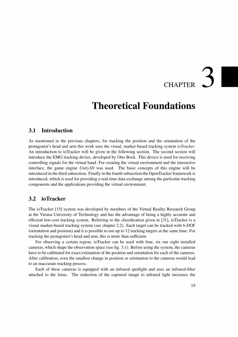
For observing a certain region, ioTracker can be used with four, six our eight installedcameras, which shape the observation space (see fig. 3.1). Before using the system, the camerashave to be calibrated for exact estimation of the position and orientation for each of the cameras.After calibration, even the smallest change in position or orientation to the cameras would leadto an inaccurate tracking process.
Each of these cameras is equipped with an infrared spotlight and uses an infrared-filterattached to the lense. The reduction of the captured image to infrared light increases the
19
Figure 3.1: Left: Tracking space shaped by 4 ioTracker cameras. Right: Functioning of anioTracker camera.
effectiveness of the tracking process, since the information which has to be processed by thetracking system is significantly reduced. The tracking targets used by the ioTracker systemconsist of several small spheres, which are covered with a retro-reflective surface1. Thesespheres are aligned in a way that they form a rotation-invariant point cloud, which allows todetermine the exact position and orientation in space. In the ideal case, due to the infrared filterattached to the cameras, each camera retrieves a black image with only the spheres of the markersused as white objects. Such a lightweight tracking target can easily be attached to almost anyobject and thereby enables this object to function as virtual interaction device. For example apen or a clipboard can be translated into a virtual environment by translating their position andorientation to virtual objects and thereby enabling the protagonist to interact with them in thevirtual world. Similarly, a tracking target attached to a head-mounted display (HMD) can turnthis display into a virtual camera, generating an image of the virtual environment (see fig. 3.2).
As one can imagine, the process of tracking has to be highly accurate. If the virtual handdoes not follow the movements of the real hand with sufficient accuracy, it would be difficult toreach for an object. Furthermore, if the position of the virtual camera did not follow the motionof the head, this could lead to so-called simulator- or cyber-sickness.
For tracking the position and orientation of a tracking target, technically images from at leasttwo cameras are required, while the minimal setup for an ioTracker system uses four cameras.The more cameras are used, more accurate and stable results can be calculated by ioTracker.Another important reason for using eight cameras, is to prevent masking of the tracking targets.This can easily occur - for example if the protagonist holds the arm (stump), attached with atracking target, in front of his body. This would mask the target for all cameras, which arelocated behind the protagonist. Since masking a tracking target would lead to an absence of
1A retro-reflector is able to reflect the impacting light back to the emitter with a minimum of scattering.
20
Figure 3.2: Two examples of ioTracker tracking targets, attached to a HMD (left) and a pen(right).
tracking data, which is needed for real-time synchronizing the virtual prosthesis and even moreimportant the virtual camera1, this situation should be avoided.
Even though the cameras of the Opentracker system only detect the reflected infrared light,tracking errors could occur if any surfaces other than the spheres of the tracking targets reflectinfrared light to only one camera. Therefore, for achieving the best tracking results, all reflectingsurfaces have to be covered or hidden from the cameras. As daylight also contains infraredradiation, it should be avoided by darken the room the ioTracker system is set up in, which hasthe additional benefit of creating a better contrast for the protagonist wearing the HMD.
For distributing the generated tracking data over a network or to other applications, ioTrackerprovides an interface to the OpenTracker framework, which will be introduced in chapter 3.5.
3.3 Otto Bock EMG Tracker
An introduction to electromyography (EMG) is given in chapter 2.3. In short, electrodes areattached to the skin of the protagonist to measure the electrical activity of the underlying skeletalmuscles. This makes it easy to (dis-)connect such a device without the need for a surgicalprocedure. The disadvantage is the inaccuracy and unsteadiness of the measured signal andrequires an efficient and complex correction of the signal. By using technologies like patternrecognition, the signal recorded by the electrodes can be translated into a controlling signal. Thestronger a muscle is contracted, the higher the resulting controlling signal. This process is achallenge of its own and has been omitted in this work by using the EMG tracker technology ofOtto Bock. This, furthermore, has the advantage that the reactions of the virtual prosthesis arequite similar to, at least, a prosthesis made by Otto Bock.
The EMG tracking device used in this work is embedded in a wristband, together with twoEMG electrodes for tracking the signals for opening and closing the hand. This setting is similar
1Masking a target can cause slight jittering of the camera or arm up to rapid jumps, which can cause cyber-sickness.
21
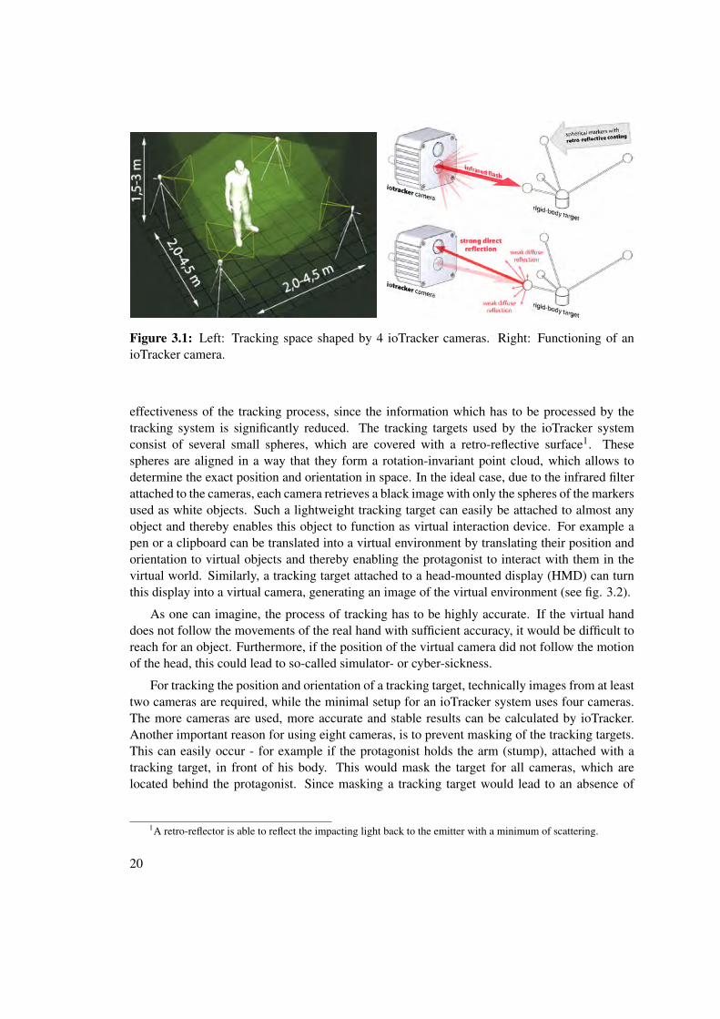
Figure 3.3: An illustration of the OttoBock EMG tracking device, embedded in a wristband.Communication to the computer is established via the bluegiga WRAP THOR module, which iscapable of connecting to another Bluetooth device (the EMG tracker), and accessable from thecomputer via a virtual serial port. For capturing the EMG signals, two electrodes are embeddedin the wristband as well and connected to the tracking device.
to the controlling electrodes in the stem of a myoelectric prosthesis. For communicating with thecomputer, a WRAP THOR module is used, which provides a virtual serial port at the computerfor sending and receiving bytes. Furthermore, this interface implements the Bluetooth protocoland is able to connect to any Bluetooth device. This allows a wireless communication betweenthe computer controlling the simulation and the protagonist wearing the EMG tracking device.
For sending and retrieving data, the OpenTracker framework was extended by an inter-face(module) capable of establishing a connection through the serial port to the WRAP THORmodule, and furthermore to the EMG tracking device. The OpenTracker framework will beintroduced in chapter 3.5, while a detailed description on the implementation of the OpenTrackerinterface for the EMG tracking device is given in chapter 5.4.
3.4 Unity3D
The Game engine Unity3D1 is a complete developing environment, providing possibilities forcreating 3D scenes with objects and lights by clicking and dragging, much the same as 3Dmodeling software, but with the exception that 3D objects cannot be created or modified. Thismakes it very easy to set up or rearrange a 3D scenery. But in contrast to modeling software,each object can contain several scripts which are capable of modifying all of the object’s scriptsas well as other objects respectively their components. For example, such a script could beused for opening a door when entering a certain area. Thereby it is possible to make the sceneinteractive.
This is done by combining the objects in the scenery with scripts which literally bringthem to life. The system of managing these objects and scripts is introduced in the first threesubsections.
Unity3D comes with the built-in physics engine PhysX from NVIDIA. This actually influ-enced the process of solution finding of this work, as a first approach of creating the graspinginteraction by making use of the physics engine was not satisfying and finally led to a simplifiedinteraction process. The physics engine will be introduced in subsection 3.4.5.
Concerning multiplayer gaming, Unity3D uses the open source multiplayer game networkengine RakNet. This engine makes it possible to use the objects as mentioned above for directlycommunicating over a network with other objects from another application. The technical aspectof using the network engine of Unity3D will be explained in detail in the last subsection.
For performance issues, each application built by Unity3D automatically provides optionsfor resolution as well as for rendering quality regarding textures, lighting and shaders. Thiseasily allows to adapt the performance required of the simulation to the capacities of thecomputer.
Especially for prototyping, but maybe also for creating the final software, using Unity3Dsafes a lot of time since a lot of functions needed to create a VR simulation are already providedand experimenting as well as debugging is very easy due to the graphical interface of Unity3Dand the possibility of real time editing. However, as Unity3D is a game engine, some specialrequirements like an extended window and widget system might not be fulfilled. Tasks whichrequire real time or at least an accurate time control might not be possible to implement due tothe fundamental Unity3D processes in the background which cannot be influenced. Therefore,it might be useful to prototype applications in Unity3D, but use less dynamic and powerfuldevelopment environments (if at all) for creating the final product. With an appropriate approach,a lot of the written code could even be reused.
3.4.1 GameObjects
A GameObject is the base class for each entity used in a Unity3D scene [29]. It contains aname which does not have to be unique and a Transform component, which defines the objectsposition, orientation and scale in the scenes coordinate system. Furthermore, GameObjectscan be tagged and applied to various layers which themselves can be defined in Unity3D.In this work this is used, for example for providing different rendering contexts inside oneUnity3D scene. Another important functionality of GameObjects is their capability of beinghierarchically composed. Each GameObject can contain other GameObjects as children. If aGameObject is a child of another GameObject, its Transform component’s position, rotationand scale are relative to the position, rotation and scale of the parent’s Transform component.Only if a GameObject has no parent, its Transform values are global1.
The real power of GameObjects is due to the fact that they contain components. Asmentioned above, each GameObject contains a Transform component which manages theGameObjects position, rotation and scale. This component is a fundamental requirement for
1Meaning that they are relative to the scene’s origin and rotation, both zero vectors and the original scale of onein each dimension.
23
a GameObject and cannot be deleted. But in addition to the Transform component, any numberof components can be added to this GameObject.
3.4.2 Components
A component is basically a script and can be applied to a GameObject. There are severaltypes of premade components for any purpose, like Mesh Filters for holding geometry data,Mesh Renderers for rendering the geometric data provided by a Mesh Filter with a certaintexture, Cameras for providing view ports the scenery can be rendered through, Lights, ParticleSystems, Physics components, Audio components, Networking controls and many more. For eachcomponent, a setting interface is provided by the Unity3d editor for adjusting the component asneeded.
One benefit of components is that they can also be created from scratch by the developer.Each component (script) is derived from the class MonoBehaviour and provides several override-able functions which are accessed by the main loop of the Unity3D application [29]. Themost important ones to be mentioned are the Start function, which is executed after loadingthe application and can be used for an initializing process, and the Update function, which isexecuted every frame.
Figure 3.4: Examples for setting interfaces of self made components.
Another very useful feature of the self made components is their capability of providing asetting interface for the Unity3D editor like the premade components do (see figure 3.4). In gamedeveloping this allows the level designers and artists to work with components at a “higher” levelwith no need to be confronted with the written code. Based on this idea, and assuming that the“experts” using the simulation are skilled in using Unity3D, this would allow a high degreeof flexibility in creating testing environments and other adjustments to the scenery. Withoutusing the Unity3D editor, this would require a complex user interface inside the application.The settings interface can be easily defined by simply defining public variables for the derivedMonoBehaviour class. Each public variable is displayed in the settings interface according to itsdata type. Therefore, text has to be typed, while number values can be typed, but also definedcontinuously by clicking and sliding. Boolean expressions are displayed as checkboxes, pointersto other classes (components) provide a window for selecting the appropriate components or can
24
be defined by directly dragging another component onto this parameter and even enumerationdata types are possible to use as parameters, providing a drop-down menu with the respectiveitems.
Finally another feature of components is the possibility to define requirements of othercomponents for being used. For example, if a component has to communicate via network,a NetworkView component is required (see 3.4.6) and ideally should be applied to the sameGameObject as the other component. Such a requirement for the NetworkView component canbe defined by adding the line [RequireComponent (typeof (NetworkView))] directly in top of theclass declaration. This also works with self-made components and has the effect that if such acomponent is applied to a GameObject in the Unity3D editor, the other components requiredare automatically created and applied to the GameObject as well. This makes it much easier -especially for non-expert stuff like artists and level designers - to stay on top of things.
3.4.3 Prefabs
Prefabs are used to save and load hierarchies of GameObjects as they are created in the Unity3Deditor. Each of the GameObjects in the hierarchy can contain several components with theirparameters specified. Even saving a whole level as a prefab would be possible. However, inthis work no levels are required, and prefabs especially are used for multiple used GameObjecthierarchies like the virtual arm containing the prosthesis with all its individual parts. Thisstructure all in all is used four times1, another example are the Training Objects, which are usedfor being grasped by the protagonist. When changing a prefab or a component of a prefab, eachoccurrence of this prefab in any scenery saved is also affected. If the user changes parametersor the structure of a prefab, which is used in the scenery loaded in the editor, the hierarchicalstructure gets detached from its binding to the prefab and is not affected by changes of the prefabanymore.
Since prefabs can help to save time in the process of level creation, this would already be agood reason to use them. However, another even more important reason is the fact, that prefabsare intended for being created and destroyed at run-time. Each prefab can be used for creatinginstances of itself during runtime. This allows to create dynamically huge amounts of objectslike trees or - as it is required for this work - Training Objects.
3.4.4 Assets
For including any form of content into a Unity3D scenery, which cannot be loaded directly bycomponents, assets are used. An asset can contain scripts, shaders and textures, but also prefabs,which again contain GameObjects with components. Generally, an asset can be considered acontainer for embedding resources, which are saved on the hard drive as a particular file. Thisfile can be a prefab file, a Unity3d scene file, a text file containing code, a 3D mesh or any typeof media as an image, sound or video file. Unity3D is capable of importing a huge range of
1The structure is used in the client application, in the big 3D monitor of the server application and in the VirtualArm Settings window preview of the server application. The Hand State Editor inside the server application onlyuses the prosthesis without the arm, which is a prefab itself and included in the other prefab containing the virtualarm as well. Apparently it is also possible to create hierarchical structures using prefabs instead of GameObjects.
25
common media file formats and is capable of several coding languages as Javascript, C# andBoo to be used for developing components and several shader languages up to ShaderLab fordeveloping shaders.
3.4.5 The Built-In Physx Engine
For physics simulations, as they are commonly used in 3D video games, Unity3D offers the built-in Physx engine. This engine provides features such as clothing simulations, the definition offorces and (partly) move-able joints, all of them provided as components, which can be attachedto a GameObject. For the physics simulation which was created in this work, two furthercomponents are used, Colliders and Rigidbodies. These two components will be introducedin the following.
The Rigidbody component allows a GameObject to be influenced by the physics simulation.To be more precise, the Rigidbody component influences the Transform component of theGameObject it is attached to. Added to an empty GameObject, without any components than therequired Transform component, the Rigidbody component would cause the GameObject to falldown - according to the gravity force defined in the settings. Usually, Rigidbody componentsshould not be moved by using the Transform component since this would falsify the physicssimulation. The required behavior for the virtual hand, being translated and rotated by the user,but still being able to interact with other physics-controlled Rigidbodies, can be achieved bysetting the Rigidbody to the kinematic state. This stops any movement, caused by the physicssimulation (even such caused through forces like gravity), and gives back full control over theGameObject’s position and orientation to its Transform component. Another parameter, whichwas important in this work, is the type of collision detection to be used. For objects, whichare moving around in a - at least for the physics engine - unpredictable way, like the prosthesisdoes, Continuous collision detection has to be chosen. For all GameObjects, which have aRigidbody component attached to and are controlled completely by the physics simulation,Discrete detection is sufficient.
With this setup of components, the GameObject would fall through any other object becauseno collisions can be recognized. For being able to do this, first a “physical” body for theGameObject has to be defined. This is done by attaching one or several Collider components tothe GameObject. A Collider component is available in several shapes, such as a box (cuboid),sphere or capsule (a cylinder with rounded ends). Furthermore a mesh Collider, which uses anattached mesh for defining the surface of the physical body of the GameObject, is provided. Thecontrol mesh for this last type of Collider is limited to 255 triangles, and the mesh has to beconvex. Since it is possible to add several colliders of different types to refine the physical bodyfor a Rigidbody component, in this work only the first three types of Colliders are used togetherfor creating the required physical shapes. For creating immovable barriers like a floor, whichkeeps things from falling through it, an additional Rigidbody component is not required, unlessthe floor is intended to move around as well.
Besides its capability of causing collisions, the Collider component has a secondary func-tionality which also has been used in this work. If a Collider component is set as Trigger, itdoes not influence the physics simulation at all, but still generates three events: when enteringan intersection with another collider object, while staying in the intersection, and when leaving
26
the intersection. This trigger functionality can be used, for example, to detect if an object enters,is inside or leaves a certain area, without influencing the physical behavior of this object.
3.4.6 About Networking in Unity3D
For supporting the creating of multiplayer games, Unity3D provides the built-in open sourceengine RakNet. RakNet’s functionality is implemented in Unity3D by the class Network1. Forbeing able to perform any data exchange among the components, first a connection has to beestablished. This has to be done the following way: RakNet provides a server/client structurewith the idea of having several game clients running at the users computers, which all areconnected to a game server. The server notices, when a user logs on or off, and furthermorecan be used for managing the action happening in the game.
After a server has been started and a client established a connection to this server, it ispossible to communicate directly from component to component. For example, the component,responsible for moving the fingers of the hand, can share this information with each otheroccurrence of itself in the network, ensuring that all occurences of hands in several applicationsare moving simultaneously. This is achieved by using remote procedure calls (RPCs), whichallow to execute functions in another application on another computer via network.
The RPC implementation of RakNet in Unity3D allows to use several data types as pa-rameters of RPC functions. These data types are integers, floating point numbers, strings andfloating point vectors in R3 and R4 (quaternions) [29]. For the execution of a RPC function, thebuilt-in NetworkView component is required, and has to be added to the sameGameObject, thecomponent initiating the execution is attached to. A certain RPC function can be addressed by itsname, if the other application has a NetworkView component with the same NetworkViewID thanthe one which is used for executing. Additionally, a component implementing the executed RPCfunction has to be attached to the same GameObject as the NetworkView component. basically,this is the procedure any communication between server and client application (components)is performed. Almost each component created for this work, which has to communicate overnetwork, is able to update instances of itself. Each of these components can be marked “assender” or “as receiver”. Even both options are possible at the same time, causing the incomingupdate to be sent to further components. This can be useful, if one client has to share informationwith all other clients and the server. In such a scenario, the request would first been sent to theserver and from there forwarded to all clients.
3.5 OpenTracker
The OpenTracker framework serves as an interface for transmitting tracking data in a highlymodular approach. The process of transmission can range from just passing on data throughserving as an interface between different communication channels2 up to processing the incom-
1In this work the network functionality of Unity3D is only used for establishing data communications betweenthe client and the server application. Data exchange from and to the Unity3D applications is performed through theOpenTracker framework.
2Like network and software protocols or even direct executing of function stacks.
27
ing data through several filters and modification modules. The focus of OpenTracker besideskeeping high modularity and high performance in processing data was focused on the attempt toprovide an easy, flexible and fast to change end user configuration, which can even be supportedwith graphical tools [26].
In this work, the OpenTracker framework is used for establishing data streams from theioTracker Software into a Unity3D application for each tracking target. Furthermore, the frame-work provides the interface for the bidirectional communication between the EMG trackingdevice developed by Otto Bock, and the Unity3D application. The advantage of OpenTrackerthereby is the possibility of splitting this process, which can be rather complex, into the part ofexchanging data between the EMG tracking device and the OpenTracker framework on the oneside, and exchanging data between the OpenTracker framework and the Unity3D application onthe other side. Following this logic, for establishing an interface from ioTracker to Unity3D, itwas also possible to make use of the already mentioned connection between OpenTracker andUnity3D after receiving data from ioTracker in the OpenTracker framework.
3.5.1 Modules, Data Sources, Data Sinks and Events
The task of sending and receiving data between a certain data source or sink and the OpenTrackerframework is handled by a so-called module. Each module usually consists of one or more datasources and data sinks, but it is also possible for modules to just provide sinks or sources forunidirectional communication.
A data source creates an event, which usually contains a position, an orientation and a time-stamp value as a minimum requirement of data needed for tracking a single ioTracker target.To each event, additional attributes can be attached, containing string, integer or floating pointvalues. After an event was created by a source, it is pushed into the OpenTracker framework andmoving through all specified modules, until it reaches the last data sink of the data flow. Duringits way through the OpenTracker framework, the data flow can pass several filters and modifiers,but it can also be split or merged. This allows a highly dynamical setup and easily swapping orreconfiguring of input- as well as output-devices or -applications, and is claimed to be a “writeonce, track anywhere” approach [26].
This approach of an setup easy to reconfigure is reached by using a XML file. Each data flowstarts at a data source, described by a XML tag and related to an implemented OpenTracker datamodule (which are usually containing a sink and a source). For sending data to a special sink,the data source tag has to be inside a data sink tag. This sink tag again can be inside anothersink tag, causing the data to be forwarded. At the beginning of the XML file, the configurationfor each module used in the data flow can be specified.
In figure 3.5, the composition of a sample configuration file is illustrated. In the moduleconfiguration section at the beginning, a parameter for the Console module is defined. After theconfiguration section, a single data flow is defined. The data is pushed into the OpenTrackerframework by a VRPN (Virtual Reality Private Network) NetworkSource, which is capable ofreceiving data, which was sent by the appendant VRPN NetworkSink. The generated data eventafterwards is sent to the EventTransform module, which changes the scale and the rotation of theincoming tracking data. This is possible, because OpenTracker provides the mentioned aboveevent data type, which clearly specifies a position and orientation value. After being scaled and
28
Figure 3.5: Example of an OpenTracker configuration file.
rotated, the event reaches the UnitySink which causes the data to be pushed into the Unity3Dapplication. The data flow in the OpenTracker framework is still not finished after this action,because the data yet has not reached the very last sink in the configuration. In this example,as illustrated in figure 3.5, the last sink is a ConsoleSink, causing the tracking data event to bedisplayed in the console window.
3.5.2 Adding modules to OpenTracker
As already mentioned, this work uses OpenTracker as an interface in order to receive the requiredtracking data, which is created by ioTracker and the OttoBock EMG tracking system, insidea Unity3D application. IoTracker was developed at the Technical University of Vienna andfortunately is compatible with the OpenTracker interface. This means, that the packages ofdata sent by ioTracker can directly be received by a VRPN Network Source. The connectionto the EMG tracking device on the other hand is established through a serial port (COM),data is transferred by an individual protocol. These circumstances require an adequate processof reading data and pushing it into the OpenTracker framework, or - the other way round -receiving data from the OpenTracker framework and writing it into the serial port, keeping thespecifications of the individual communication protocol.
In short, a OpenTracker module had to be implemented, which is acting as an interfacebetween the EMG tracking device and OpenTracker. In the following, the process of creating anew module and adding it to the OpenTracker framework will be explained in general. For moreinformation about the specific implementation of the described data-flows from ioTracker or theEMG tracker to the Unity3D applications above, please have a look at the chapters 5.3 and 5.4.
Each OpenTracker module class derives from the classes NodeFactory and Module (orThreadModule, which itself derives from Module). In contrast to Module, ThreadModuleprovides functions for using a module-internal thread, for example, for receiving data through a
29
serial port. This class provides the following virtual functions, which then have to be overriddenby the specific implementations of the respective module:
Module
• void start(): The start function is intended to start the module, right after initializationwas done. When using this method from inside a ThreadModule, usually the the originalThread::start() function is called here.
• void close(): For closing the module and clearing all resources used by the module, thisfunction can be reimplemented. Additionally, when used inside a ThreadModule, theoriginal Thread::close() function has to be executed, which deletes the thread.
• void init(StringTable& attributes, ConfigNode * localTree): For initialising the module ifnecessary, this function can be overridden. The parameters, which are passed with thefunction call, are defined in the module configuration section of the configuration XMLfile (see 3.5). As mentioned above, when used inside a ThreadModule class , the originalThread:init(...) function should be called at first, which then sets the initialisation flag forthis module.
• void pullEvent(): This function can be implemented for pulling events out of the Open-Tracker framework. It is called, after pushEvent was executed on any other module.
• void pushEvent(): For pushing events into the framework, this function can be imple-mented. However, in this work no use was made of the pushEvent() and pullEvent() func-tions, since the same functionality is provided by other functions, as onEventGenerated.More details about this approach are given after this itemization.
ThreadModule
• void run(): This function executes the internal receiver (and/or processing) loop in anindividual thread. Such a thread is, for example, required for properly receiving data froma serial port (from outside the OpenTracker framework, and pushing it forward into theparticular Data Source(s) of the module.
NodeFactory
• Node * createNode( const std::string& name, const StringTable& attributes): This func-tion is called for initialization as well, while the configuration XML file is processed. Eachtime, a data sink or source is defined in the configuration, this function is called, meant tocreate the respective sink or source class for the module. After the successful creation ofa Sink or Source, this is passed as return parameter.
Additionally, the ThreadModule provides a void lockLoop() and void unlockLoop() function.These functions are not meant to be overridden, but used for safely getting data from-, or settingdata to any variables used in the receiver loop. By locking the loop before any operation and
30
unlocking it afterwards, it is ensured that the receiver thread will not modify these variables inthe meantime. In order to receive data at a data sink and forward it out of the OpenTrackerframework, no receiver loop is needed. Instead each data sink provides an event handler, namelythe function void onEventGenerated(), which is called each time an event was received. Similarto this, each source provides the function void updateObservers(Event &data) for triggering thisevent handler at all attached sinks.
As just mentioned, the module itself would be worthless without the implementation ofdata sources and sinks, as they provide the real interface to the OpenTracker framework byencapsulating the data into an event. Both, sinks as sources, derive from the class Node, whichhandles quite everything by itself - the only thing which has to be implemented, is the handlingof pushing and pulling events.
3.5.3 The Unity3D Interface
Since OpenTracker is written in C++ and Unity3D C# is based on the .NET framework, aninterface is required for gaining access to the C++ OpenTracker functions from inside Unity3Dcode. This interface is part of the ARTiFICe framework, which was originally created by theInteractive Media Systems Group at the Vienna University of Technology [21]. In short, theinterface provides a C# wrapper for several OpenTracker classes, respectively functionalities.Most important in this work are the Tracker class encapsulating the OpenTracker UnitySink,and the TrackingEvent class providing the basic OpenTracker event functionality.
Basically, the interface provides the class Tracking, which allows to get access to a certainUnitySink by calling the getTracker method. The certain sink is identified by passing its name,as is was defined in the XML file, as parameter with the function call. The class returned bythis getTracker method is the already mentioned above Tracker class and basically encapsulatesthe OpenTracker UnitySink class (C++) for accessing received OpenTracker events in Unity3d(C#) [21].
For this work the Tracking class was extended for providing access to UnitySources as well,especially for sending events. The UnitySource class had to be added to the OpenTrackerframework as described in the chapter above. For sending an OpenTracker event through acertain class, the Tracking class was extended by the generateEvent function, which passes thename of the source and the tracking event as parameters and causes the passed event to beforwarded into the OpenTracker data flow. This extension enables bidirectional communicating,respectively sending and receiving OpenTracker Events from inside Unity3D. More informationabout the implementation of this extension can be found in chapter 5.4.
31
CHAPTER 4Interface and Application Design
This chapter discusses the creation of the virtual environment as well as the basic applicationdesign of the underlying software system. The client/server structure is introduced, which sep-arates the system into two Unity3D applications. By introducing these applications, especiallythe server, which allows to define the process of the simulation, an overview on the scope offunctionalities, provided by the virtual reality system, is given. Finally, the design of the graspinginteraction will be presented.
Since the attempt was made to place the design of the user interface above the technicalcreation of the system architecture, in the following text, those two parts will be treatedseparately. In this chapter, the technical aspect of the implementation is left out to the extentthat is possible, and will be presented in chapter 5.
4.1 Hardware Setup
The ioTracker system is set up in a room with eight cameras, which are aligned such that they canobserve a space in the middle of the room with approximate dimensions of 4x4x3 meters. Insidethis space, the protagonist is able to interact with the virtual environment. For visualization of theenvironment, the protagonist wears a head-mounted display (HMD), provided with a trackingtarget for determining the position and orientation of the virtual camera.
A HMD is usually built with two small LCD displays, one for each eye, and is thereforecapable of stereoscopic viewing. This means, that each eye receives a slightly different picture,as it is true in the real world. The brain uses this difference, or binocular disparity, to “calculate”depth in the visual scene. The greater the displacement of an object when comparing thesetwo pictures, the greater the distance of the object to the eyes. Stereoscopic viewing is a built-in functionality provided by the graphic adapter, and does not have to be implemented in theapplication. For sending both pictures, they are displayed in an alternating fashion.
As mentioned in chapter 3.3, the EMG tracking device provides wireless communication forsending controlling signals to the simulation. This setup allows for a much more natural and
33
authentic experience while interacting, since there are no issues of concerns regarding twisting(even oneself into) cables. For keeping this benefit, even when using a HMD, the protagonistwears a backpack, including a LiPo accumulator-powered supply for the HMD and for a wirelessvideo (WHDI) receiver for retrieving video data for the HMD. More information about this setupcan be found in [7].
Figure 4.1: The protagonist (right) is wearing a HMD attached with a tracking target. A secondtarget is mounted to the forearm of the protagonist and translates this position to a virtual arm.The picture displayed in the HMD is also visualized by a video projector.
The control of the virtual hand, or more specifically, the control of opening and closingthe hand is performed by EMG signals, as already mentioned. For controlling the position ofthe whole hand, which is attached to the forearm, many different approaches can be found inliterature (see chapter 2.4.1). These reach from simply tracking the position of the hand (3-DOF), up to determining the bending of the elbow and the position of the shoulder as well. Forthis work it has turned out to be sufficient for a tracking target to be mounted at the forearm (orupper arm) of the protagonist, at the position where the stem of a prosthesis would begin. Theposition and orientation of this target (6-DOF), translated to a virtual arm and subsequently tothe virtual hand, allows a natural experience of moving around.
In order to make the output of the HMD visible for other people to see, the video signalcreated by the computer is split and also sent to a video projector (see fig. 4.1). As explainedin more detail in the following chapter, another screen (if necessary, on another computer) isprovided for the monitoring and the controlling of the simulation process, and, for example, forguiding the training exercises.
34
4.2 Basic Application Design
As mentioned in the chapter before, for visualization of the virtual environment, the protagonistwears a head mounted display (HMD). Such a device is usually connected to the computer bythe common DVI/HDMI display port and shows the same image that would be visible on amonitor connected to the display port. Therefore, the easiest way to create the image output forthe head mounted device is an application, running in full screen mode and rendering the virtualenvironment through the perspective of the virtual camera in real-time.
Since common graphic adapters usually support the connection of two devices, for examplemonitors, it is appropriate to use the HMD as one device, while the other can be used fordisplaying an observation application for analyzing or guiding the action performed in the virtualenvironment on a monitor, for example, when performing exercises with a patient.
Following this idea, the decision was made to split the environment software up into twoapplications, one for creating the visual output for the HMD, and the other functioning as acontrolling application. The decision of creating two applications instead of one, providing thesetwo windows was made for several reasons. First, the free version of the game engine Unity3D,used for creating the virtual environment, restricts an application to one window. Another reasonwas the benefit of having two applications, capable of communicating with each other via anetwork. In the first subsection, the client/server structure will be presented in detail.
In the second subsection, a theoretical concept of extending this structure by one or morespectators is presented. Such an extension allows for the option of having more than oneprotagonist which is equipped to interact with the virtual environment and provides the option,for example, of creating collaborative exercising scenarios.
4.2.1 Client/Server Structure
As both the client and the server application are communicating to each other over the UDPnetwork protocol, even if used on the same computer, the rate of synchronizing the receivedtracking data (at one of the applications) is limited. In order to reduce the latency of the virtualreality system to actions of the protagonist, the decision was made to retrieve and processincoming tracking data directly at the client application, which creates the visual output forthe protagonist (see figure 4.2). Following this idea, and due to the requirement of creatingbidirectional communication to the EMG tracking device, this whole process, including datatransfer, also had to happen in the client application.
The built-in network engine of Unity3D called RakNet, is used in updating the positionof the virtual arm and hand at the server application. The server manages the creation anddestruction of the virtual objects used in the environment, and provides possibilities of changingparameters for several aspects of the simulation, most importantly mapping the created EMGcontrolling signals to a certain behavior of the prosthesis. If one of these parameters changes,this information is sent to the client. The client again processes the received tracking data forthe purpose of positioning the virtual camera and arm, and according to the parameters definedby the server, the EMG signals are translated to move the prosthesis. All these motions are sentto the server, whereby the demand of providing them in real-time is not given.
35
Figure 4.2: A work flow graph for the client/server structure. The blue arrows illustrate the dataexchange between the client application and the tracking systems using OpenTracker, while thered arrows show the communication among the Unity3D Applications using the internal RakNetengine. The yellow arrows illustrate the video data generated for the HMD and a second displaydevice.
This setup allows for the retention of the client application as purely an output, with(rather) no traditional GUI elements which are controlled by mouse and keyboard. Instead,the protagonist only interacts by using the virtual hand. All elements for interactions, whichmust be performed by mouse and keyboard, are placed at the server application.
For both the OpenTracker framework and also for the communication between the particularUnity3D applications, it is possible to exchange data over network. This allows for theencapsulation of the performance intensive task of tracking as performed by ioTracker to berun on a particular computer. This can also be done for the client application, which is noless important for achieving a minimal latency of the system as a whole. However, it is worthpointing out that, for this work, it was possible to run all applications on one computer, asmentioned at the beginning of this chapter.
4.2.2 Theoretical Spectator Extension
Since the client/server structure, provided by the built-in network engine of Unity3D, allows forthe creation of multiple clients, it is appropriate to extend this structure by an additional VR spec-tator. This second virtual reality interface could be used, for example, to create “multiplayer”rehabilitation games, where exercises have to be performed in a team. In consideration of thefact that a protagonist’s motivation is one of the most important requirements for the success
36
of a rehabilitation game, such a “multiplayer” mode could help immensely. Another sampleapplication would be to have an expert advising the protagonist from a first person perspectivein reality. The experts arm could be optically tracked, enabling the expert, for example, to pointat virtual objects. Watching the behavior of the protagonist from this perspective might also bebeneficial in some situations.
Figure 4.3: Spectator Extension work flow graph for the Client / Server structure. The bluearrows illustrate the data exchange between the client application and the tracking systems usingOpenTracker, while the red arrows show the communication among the Unity3D Applicationsusing the internal RakNet engine. The yellow arrows illustrate the video data generated for theHMD and a second display device.
For adding a second person to interact in VR, a second HMD, applied with a tracking targetis required. A second arm tracking target would also be useful in providing a virtual pointingand interaction device. This task can easily be undertaken by ioTracker, since the use of up to12 tracking targets is supported. A third Unity3D application would be needed to create theoutput image for the HMD, which directly receives the tracking data of the spectator’s headplus arm target positions from the OpenTracker framework, for keeping the minimal latency aswell for the spectator’s output image (see figure 4.3). It is conceivable that a second protagonistcould even be located remotedly, for example, at home (which often occurs in the context ofrehabilitation). The provided RPC system (see chapter 3.4.6) for communication between the
37
server and the client(s) can easily be modified for distributing the head and arm position and thehand state of the prosthesis.
4.3 Client Interface - Performing the Interaction
As mentioned before, the client processes the incoming tracking data and generates an imageof the virtual environment through the virtual camera controlled by the users head. Forvisualization, the model of an arm is controlled by the tracking target, which is mounted to thearm (stump) of the protagonist. For the virtual arm model, this coordinate origin can be definedby positioning a virtual equivalent of the tracking target in order to match the real position (seefig. 4.4). The bending of the elbow is not dynamically controllable by the protagonist, but canbe set in the server application, as can the length of the lower arm, in order to perfectly matchthe real-life circumstances.
For the purpose of interacting with objects, the protagonist must move the virtual hand intoa certain position over the desired object. In order to support the process of reaching the rightposition as well as, grasping, and releasing objects, some aides are available for the protagonist,such as the so-called object shadow, a grip force indicator and optical feedback for differentparts of the grasping action. These aides, along with the process of grasping, are explained indetail in chapter 4.6.3.
Figure 4.4: Left: A single 6-DOF tracking target is used to control a virtual arm plus theattached virtual hand. A second (6-DOF) tracking target is mounted to the HMD to control thevirtual camera. Right: The image of the virtual environment created by the virtual camera, as itis displayed in the HMD. The bright green circle indicates to the user that the hand is in the rightposition for grasping the underlying object.
The graphical interface of the client application essentially consists of the image generatedby the virtual camera. For additional information, a head-up-display (HUD) was implemented.In this work, the HUD only displays status information with regards to the connection status andseveral parameters set by the server. With a view to create a serious game, this HUD can easilybe extended in order to display a score and similar tasks.
38
4.4 Server Interface - Controlling the Action
The server application is the back-end part of the virtual environment. All parameters concerningthe progress of the simulation can be defined here. In the following subsections, an overview ofall functionalities of the server application is provided.
4.4.1 Main Interface
The server interface window consists of a toolbar at the top of the window and a big 3Dvisualization of the training environment (see fig. 4.5). In this 3D view, the operator of the serverapplication can view the actions performed by the protagonist through a camera independent ofthe protagonist. This camera can be translated easily by clicking and dragging the mouse wheel.For rotating the camera, the right mouse button must be clicked and dragged. The camera canbe translated forward or backward along its view-axis by scrolling the mouse wheel.
In order to customize the simulation of grasping, the toolbar at the top of the applicationprovides eight settings windows for different fields of functions. These functions range fromstarting the network server up to creating and performing exercises. In the following sub-sections, these eight control windows of the server application and the description of how towork with them will be provided. The implementation of the window system itself will bediscussed in chapter 5.2.2.
Figure 4.5: The server application in action, with several control windows opened.
39
Next to the buttons for the eight settings-windows, the toolbar contains a display of thenetwork status, indicating if the network server was started and whether the client is connected ornot. This gauge was implemented at an early stage of development due to unstable connections,and has proven to be useful in reminding the user that the network server of the server applicationhas not been started.
Finally, even farther to the right is a button captioned ’Start Logging’. This button remotelystarts and stops the process of data capturing at the client application. The Data Logger is used torecord the actions performed by the protagonist in a CSV (comma-separated values) formattedfile for later analysis. More details about the implementation of the data logger are given inchapter 5.7.3.
4.4.2 Mapping
The Mapping Window allows for the definition of a certain behavior of the virtual prosthesisfor each incoming EMG control signal. The idea behind this concept was to provide a highlyflexible system for setting up various different test scenarios. The concept of mappings and howto use them is explained in chapter 4.5.
4.4.3 Hand State Editor
Hand states are part of the mapping system and are used to move all or several parts of theprosthesis into a precisely defined position. This can be achieved by using them in combinationwith mappings 1. The interface of the editor window essentially consists of a list of all the(move-able) parts of the prosthesis, and each part can either be set to “ignored” or set to acertain position. As illustrated in figure 4.6, the first four parts, namely the two axes of the wristand the two axes of the thumb, are set to “ignore”, while the other four parts, the four fingers, areall moved near their absolute minimum position, bent towards the palm. This hand state, usedin a mapping, would have the following effect: The four fingers would move into the position,defined by the hand state, with the other four parts of the hand, the two axes of the thumb and ofthe wrist, are not moved at all.
For simplifying the creation of hand states, on the right half of the window the prosthesisillustrates the currently defined hand state. By left-clicking and dragging in the image boxcontaining the prosthesis, it can be rotated around its center to be observed from any position.Additionally, by moving the mouse wheel, the camera can be moved towards or away from theprosthesis. Information about the implementation of the 3D preview window can be found inchapter 5.7.1.
In order to use the created states in hand mappings, it is possible to save the state with acertain name, which can then be found later in the mapping settings. Furthermore, it is possibleto open and edit already created states. Since states are created as files in the sub-directoryserver_data/states/ of the server application, they can simply be removed by deleting thefile. The application should not be running when doing so.
1for more information about how to use hand states with mappings, see chapter 4.5
40
Figure 4.6: The Hand State Editor
Due to a difficulty in creating the GUI window system, the hand state editor window closesall other windows when displaying a confirm box, if more than three windows are alreadyopened. After replying to the confirm box, they are displayed again. This happens to preventthe stack order of the windows from being mixed up. More information about this technicalproblem can be found in chapter 5.2.2.
4.4.4 Training Objects & Test scenarios
This window provides controls for creating and destroying training objects, for adjusting thevirtual environment and for loading and saving exercises or evaluation scenarios. Furthermore,the various grasping aides which are available can be controlled here. Operation of trainingobjects and the process of setting up exercise scenarios are explained in detail in chapter 4.7.
4.4.5 Embedded Commands
Embedded Commands are meant to be used together with the Otto Bock EMG tracking device.These commands can be used to modify the processing of the raw EMG signals before theyare sent to the OpenTracker framework. More Information about the implementation of thecommunication process is given in chapter 5.4.
41
Figure 4.7: Left: The Embed Commands Window; Right: Example structure of the embed.xmlfile, defining the commands displayed in the window on the left.
The commands listed in the Embed Commands window are defined by a XML file, locatedin the data folder of the server application (server_data/embed.xml). The schematic of theXML file is pictured in Figure 4.8: a COMMANDLIST tag includes several, but at least oneCOMMAND tag. The COMMAND tag consists of a name, an unique ID and one or morePARAM tags. A PARAM tag consists of a name and an integer value in the interval [0, 255].
When the application is loaded, a group of controls is created for each of the definedcommands in the XML file. The parameters are listed with their predefined values to be changed,and additionally one parameter per command can be selected to be controlled via a slider. Inorder to send the command to the EMG tracker, the “S” button has to be clicked. When changingone value by sliding, as much changes per second as possible are sent to the EMG trackingdevice. This makes it much easier to test different values.
4.4.6 EMG Tracker Bluetooth Connection
This window is used for establishing a Bluetooth connection between the client application andthe Otto Bock EMG tracking hardware. The window allows one to define the serial port providedby the Bluetooth receiver. An address, port and connection mode must be defined in order toconnect to the EMG tracking device. Additionally, the number of incoming control values can bedefined here, which basically is determined by the incoming data stream created by the trackingdevice.
After a connection has been established, the text fields are set to “disabled”, and the buttonprovides the option to close the connection again. After a connection to the EMG trackingdevice has been established, it is neccesary to stop the connection before closing the Application.Otherwise, the EMG tracker would still be in connection mode, which prevents any automaticreset or termination after the Bluetooth connection got lost. More Information about theimplementation of this communication process is given in chapter 5.4.
42
4.4.7 Virtual Arm Settings
As mentioned in chapter 4.3, the virtual hand and the virtual arm are controlled by a singletracking target. Corresponding to a real prosthesis, which is mounted to a prosthesis stem, whichagain is fixed to the arm stump of the amputee, the virtual hand is mounted to the virtual arm.The reference point, on which the position of the real tracking target is translated to, functions asthe virtual equivalent of the arm tracking target. It is visualized as a wooden plate with a purplepoint in the middle, modeled on the primal tracking target used for this application (see fig. 4.8).
Figure 4.8: The Arm Settings Window displaying a virtual illustration of the tracking target.The target can be moved and rotated to be placed anywhere on the arm.
For best results in controlling the movements of the virtual prosthesis, the tracking targetmust be positioned as close to the hand as possible. Since each amputees arm stump is differentin shape and length, the position of the tracking target for observing the movements of thearm differs for each amputee. This requires the option of modifying the position of the virtualtracking target in order to match the position of the real target for ensuring appropriate handlingof the virtual prosthesis. To simplify this process, the virtual tracking target can be moved byleft-clicking and dragging with the mouse. By right-clicking and dragging, the target can berotated around its upwards axis. Rotating around the other two axes is done by the Marker Pitchand Marker Roll sliders.
For additional adaptation of the virtual arm to their respective circumstances, the length ofthe virtual forearm can be adjusted to fit the size of the protagonist. As mentioned earlier, it isnot possible for the protagonist to bend the arm autonomously by creating EMG signals. Instead,this is just a cosmetic issue. When positioning the tracking target close to the end of the lowerforearm or even onto the upper arm, the end of the 3D arm model can end up in front of thecamera, occluding the scenery from the protagonist. To prevent this, it is possible to change theangle of the cubital joint. Alternatively, the upper arm can be completely hidden.
43
Finally, an option of using a left arm and hand versus the right ones is provided. Unfortu-nately it was not possible to implement this functionality as intended, which led to several bugsduring the test phase. More information on the technical implementation of the virtual arm andon the difficulty of a left-handed prosthesis can be found in chapter 5.3.2. The implementationof the 3D preview window for defining the target’s position is described in chapter 5.7.1.
4.4.8 Network Controls
It is necessary to start a network server at the server application in order to set up the simulation.Only then is the client able to find the server application and to request a connection. After theclient has been connected, the HUD of the client application can be set to be displayed withfull or little information, or can be turned off alltogether. Furthermore, this window allows oneto define a certain port for the network address of the server. Finally, it provides a button forstarting up and closing the network server functionality.
4.4.9 Control Value Monitor
This window visualizes the incoming EMG signals as they are sent from the client to the serverapplication. Displaying can be turned on and off for each signal separately. With the “+” and“-” buttons, the temporal resolution can be increased and decreased. Since these values aresent from the client to the server with a sending rate lower than the one with which this signalsarrive from ioTracker, it is not possible to display the full resolution of the signals as created bythe protagonist. Information about the implementation of the line-chart window is provided inchapter 5.7.2. The EMG chart window was also used to perform certain user-tests with regardsto practising the creation of appropriate EMG signals. More information about this test senariois provided in chapter 6.1.
4.5 Prosthesis Mapping
For the purpose of controlling the virtual prosthesis, the simulation makes use of the EMGsignals created by the protagonist. Each muscle can affect one signal, which makes it nearlyimpossible to control a virtual hand in as many degrees of freedom (DOF) a real hand cannaturally control. Actually, the number of DOFs which are provided by common prosthesis, isonly two!
Therefore, the process of interacting with a prosthesis has to be simplified. The Michelan-gelo Hand, a prosthesis developed by Otto Bock, allows the amputee to use two controllingsignals for moving the hand between different states (e.g. opened, closed), whereas one signal isused to move towards one certain state. Additionally, by creating both signals at once, the gripof the hand can be changed between two different states. In the following text, these states willalso be mentioned as hand states.
While designing the application, one goal was to provide the option of experimenting and,therefore, there was a need in providing a high level of flexibility in how the prosthesis can becontrolled by the incoming EMG signals. To achieve this, each incoming EMG signal can becombined (even more often than once) with a certain reaction of the hand. Such a combination
44
of an incoming signal and a reaction will be mentioned as mapping in the following chapters.The number of mappings, which can be used at the same time is unlimited and practically moreor less limited to the number of incoming signals.
For combining a reaction of the hand to a specific incoming EMG signal with respect tothe creation of a mapping, there are several modes available: three for defining a motion of thehand and three for affecting the actual grip force of the virtual prosthesis. Furthermore, it is alsopossible to simulate the grip force completely inside a motion mapping. Defining and editingmappings is done in the Mapping window of the server application. In the following text, allmapping modes will be explained in detail.
4.5.1 Hand Movement Mappings
Direct Mode
This mode allows the control of a single moveable part of the prosthesis. As the virtual prosthesisis based on the Otto Bock Michelangelo Hand (see fig. 4.9), the following parts are available formovement:
• Each of the four fingers can be moved as a whole
• The thumb can be moved in two dimensions, towards and away from the palm and up ordown.
• The wrist can be moved in two dimensions. It can turn around the axis along the arm, andit can turn the hand up and down.
Each of these moveable parts can be assigned in the Direct Mode to move from one end ofits boundary to the other, either by following the rising and lowering of the EMG signal or itsinversion. For additional adaptation, the speed of the movement can modified by a multiplier.This multiplier is placed at the top of the window and called Direct Speed (see fig. 4.9).
Speed Mode
The functionality of this mode is very similar to the functionality of the Michelangelo handprosthesis, as described in the introduction of this section. Each EMG signal is used to move theprosthesis into a certain hand state (e.g. opened hand, pinch, lateral grip). The higher the EMGsignal, the faster the hand moves into the specific state. To prevent the hand from moving intoseveral states at the same time in the event of several incoming EMG signals, only the mappingwith the highest EMG signal is processed for Speed Mode. The hand states, which are used todefine the state the hand should move into, can be created in the hand state editor, which willbe explained in detail in chapter 4.4.3. As with the Direct Mode, an additional adaption of themovement speed is possible by modifying the appropriate multiplier. The control is placed atthe top of the window, called State Speed (Figure 4.9).
45
Figure 4.9: Left: The Mapping Window; Right: The Michelangelo hand prosthesis made byOtto Bock
Position Mode
Position Mode also makes use of hand states for moving the hand. In contrast to Speed Mode,only one EMG signal is used for controlling the movement between two specified hand states.If the signal is at its minimum (0), the prosthesis is in the first hand state. If the value is at itsmaximum (254), the prosthesis is in the second state. For each value in between, the prosthesisis moved into an interpolated hand state between the two specified ones according to the signal.Since inversion of this mapping can easily be done by swapping the first and second state, noinversion of the signal is needed in this mapping mode. Furthermore, it is not possible to modifythe speed of the movement since each value between 0 and 254, as received from the EMGtracking device, is related to a position in the interval [0, 1] – interpolating between the twodefined states.
4.5.2 Grip Force Mappings
In contrast to the previous mapping modes presented, the following modes are not used formoving the hand, but only for modifying the actual grip force of the virtual hand. Originally,grip force was introduced in the beginning of the second part of this work, and implemented asa result of creating closing signals while already holding an object. Then, the requirement wasgiven to provide more flexibility when creating grip force. It should be possible to encapsulatethe process of creating grip force from the grasping process, and to perform it outside of thesimulation. The grip force should be defined by the use of controlling signals, which are receivedthrough the EMG tracking device (more information about the particular test scenario can befound in chapter 6.1).
46
This first led to the introduction of the grip force mappings and finally resulted in threedifferent modes which will be presented in the following. Secondly, this led to the requirementof still being able to simulate grip force in a movement mapping. These simulation modes arepresented in the following subsection (4.5.3).
Grip Force Position Mode (Griffkraft)
As the name of the mode already anticipates, this mapping mode modifies the grip force in avery similar way than it is done in the Position Mode. An incoming signal in the interval [0,255] is mapped to the grip force interval of [0, 1], where zero means “no grip force at all”, andone equals to the “highest grip force possible”. Since there are no states to swap, like in thePosition Mode, an invert option for this mode is useful to provide the option of mapping anincoming value of zero to the highest grip force as well.
Grip Force Speed Mode (Yank)
This mapping mode is similar to the Speed Mode. An incoming signal can be used for in- ordecreasing the grip force, the higher the signal, the faster this happens. Therefore, to set up theactions of in- and decreasing the grip force, two signals (two mappings) are required, like it isalso necessary for opening and closing the hand in the Speed Mode. The movement speed foradjusting the grip force can be modified with a multiplier as with the Direct Mode and the SpeedMode. This modifier is called Yank Speed.
One Way Grip Force Position Mode (Griffkraft2)
This mode can be best described as a mixture of the grip force Position- and Speed modes.This mode works like the Grip Force Position Mode, with the difference that one mapping canonly increase OR decrease the grip force. The “direction” of the mapping can be set with theinvert button. As two incoming signals are required in order to increase and decrease the gripforce, this mode appears to be quite similar to the Grip Force Speed Mode(GFSM). However, inthis mode setting the value for the grip force is still done in an absolute way, which means thatthe interval [0, 254] is mapped to the grip force interval of [0, 1]. In contrast to this mode, inthe GFSM the actual value is in- or decreased by a certain amount according to the size of theincoming signal.
4.5.3 Simulating Grip Force
As mentioned in the previous subsection, simulating grip force originally was invariably com-bined with the mapping modes, intended for moving the prosthesis. With the implementation ofthe grip force mappings, additional requirements became necessary for keeping the flexibility ofthe mapping modes. As a first, this was the option of turning the grip force simulation on andoff. Furthermore, the creation of several different grip force mapping modes, as mentioned inthe previous subsection, made it necessary to provide the options for simulating all these modesas well. As a third point, the encapsulation of the grip force calculation from the actual eventsin the VR simulation created the requirement of using additional parameters in order to ensure
47
an accurate behavior of the hand movement mapping modes when calculating grip force outsideof the simulation (see fig. 4.10). This problem regards grip force mappings, mentioned in theprevious chapter, but due to its context, this issue will be explained in the following.
Figure 4.10: Options for simulating Grip Force at one mapping. Ex1 means, that the first oneof the incoming EMG signals is used as an input.
Due to the specific implementation of the grasping process, using grip force is not possiblein the Direct Mode. This is neither possible in combination with grip force mappings, nor byusing simulated grip force. Without going into too much detail, it is not possible because in thismode no specific closing or opening action of the whole hand can be determined automatically,as only one finger or part of the hand is moved at once. More details about this issue can befound in chapter 4.6.3. In the following text, the options provided for simulating grip force andhow to work with them in the Speed Mode or the Position Mode will be explained.
Speed Mode
In Speed Mode, the difficulty of simulating grip force reached its maximum complexity becausehere it is possible to simulate any of the three grip force modes available. Furthermore, whenusing a grip force mapping for creating the grip force externally, it is necessary to additionallyblock the according movement mapping. For this special case, the box “L.O.G.K.” (Lock OnGriffKraft (german: grip force) has to be checked. In any other case, grip force is simulated. Thiscan be done in the same three ways, grip force is also mapped from an incoming EMG signal(GK = Griffkraft, GK2 = Griffkraft2, YNK = Yank, look also at 4.5.2 Grip Force Mappings).Since in GK2 and YNK mode, one mapping can only be used to move the hand or grip force intoone direction. Therefore, it is necessary to invert the simulated grip force at the one mapping,which controls the opening of the hand.
Position Mode
Position mode only allows to simulate grip force with the GK mode for a simple reason: If bothopening and closing the hand are controlled by one mapping, it is also necessary to provide thisfunctionality for in- and decreasing grip force. Since this is only possible in GK mode, the othermodes would not work here.
48
4.6 Environment & Interaction Design
As mentioned in chapter 1.2, this work is based on two consecutive problem statements. As afirst step, a virtual environment was created for grasping and moving virtual objects with a virtualprosthesis. In this first part, the main application structure and functionality was designed and aprimal grasping environment was implemented. This first approach of implementing the actionof grasping objects makes use of the built-in physics engine of Unity3D.
In the second part of the work, more specific requirements with regards to the environmentand to the interaction were given. In contrast to the first specification, grip force should beused additionally when grasping objects. This addition required to re-design the process ofgrasping objects and new grip force sensitive training objects had to be developed. It was alsonecessary to create several grasping aides for the protagonist to visualize the amount of gripforce. Furthermore, the demand was given to re-design the environment itself for a better virtualreality experience.
4.6.1 The Primal Interaction Environment
Initially, no specifications were given for creating the environment. The problem rather was tocreate the basic application structure, including the client/server applications and the extensionsfor the OpenTracker interface. In further, the hand mappings were developed and the first versionof the interaction environment was designed. The environment, as illustrated in figure 4.11, wascreated with the idea of providing a comfortable, optically pleasing surrounding for exercising.It includes a stonelike plate, matching the dimensions of the tracking area, which is placed ona lawn. For easier orientation when moving the head around, the background was replaced bya skybox1, which is providing an all-surrounding background image. The stone plate visualizesthe actual area of interaction, which is limited by the tracking area. A table is placed on the stoneplate, containing objects which can be grasped. However, besides of grasping these objects fromthe table and moving them around, no further options of creating exercises were provided.
The objects intended to being grasped were simple geometric bodies like cubes, cylindersand spheres, and could appear in different colors. For grasping an object, the protagonist hadto move the opened hand towards an object and then manage to close the hand while keepingit over the object. Which sounds like the description of a very natural and daily situation hasproven to be quite challenging when performed in virtual reality. For example, when grasping acylinder, one had to take care of not pushing it away. This could easily happen by touching theobject, even just with the tip of a finger, when moving the virtual hand towards it.
In order to create a realistic behavior for the interactive objects when being grasped, thebuilt-in physics engine PhysX was used. The simulation provided by the physics engine allowsto simulate gravity for objects as well as collisions with other objects in the scenery. The ideabehind using the physics engine was to simulate the collisions between an object and the hand,for simulating a realistic behavior when the fingers start colliding with it. Objects like the tableshould not be influenced by the virtual hand at all. Unfortunately it turned out, that avoiding to
1 A skybox is a huge cube, which is placed behind and outside of all other objects in the scenery. Its geometry istextured, for example, with images of the sky and creates the illusion of a far-away background.
49
Figure 4.11: Left: The environment design, as it was used in the first part of the work. Thetask was to simply grasp the objects on the table by closing the virtual hand around them, andmove them around afterwards. Right: The training objects used in this first design were shapedas cylinders, spheres and cubes.
push the objects away was even more challenging than grasping itself, which should have beenthe actual exercise.
Furthermore, when the virtual hand was closed around an object, the protagonist had to takecare in order to not lose it again while carrying it around. To avoid this problem, the object aboutto be grasped was “glued” to the virtual hand, after touching the index finger and the thumb of thevirtual hand at the same time. Nevertheless, some problems could not be solved, as the objectssometimes were sticking inside the prosthesis palm without any option for the protagonist torelease them again. More information about this difficulty can be found in chapter 5.6.1.
In summary, this approach of implementing the grasping interaction was not capable ofcreating a satisfying grasping experience, especially due errors resulting from the physicssimulation. With regards to the actual goal of exercising the interaction of grasping objects,this approach was not sufficient.
4.6.2 The New Environment Design
Several circumstances led to the development of a new environment and interaction design. Firstof all, the use of grip force for the grasping process made it necessary to re-create the wholeinteraction. Furthermore, the problems which were experienced with the primal implementationof this process required to improve the interaction as well. Therefore, the decision was madeto create a new, less realistic grasping process without the use of physics. The new grip forcesensitive training objects allow to specify a certain interval of grip force for each. In order to beable to grasp and move around the particular object, the grip force created by the protagonist hasto be inside the specified interval. If the grip force exceeds the boundaries of this interval duringholding and moving an object, it gets lost and has to be grasped again. Additionally, it is possibleto increase the difficulty by setting the training objects to “destructible ”. This option causes theobjects to “explode”, if the grip force exceeds the upper boundary of their force intervals.
50
Figure 4.12: The second and final environment design.
In the new design, the shapes of the training objects have been reduced to spheres for acertain reason: When grasping a sphere, it is of no significance for the grasping action, fromwhich direction the hand is moved towards the object, since the shape of a sphere is the samefrom any direction. Therefore, it is much easier for the protagonist to grasp an object, since thevirtual hand does not have to be aligned additionally. As adopted from the first part of the work,the objects can appear in three different colors, namely red, green and blue. By default, each ofthe colors stands for a certain grip force interval.
Another specification for the second part of the work was to reduce the furnishing of theenvironment and to replace the sky by a black background. This finally resulted in a veryminimalist design, only consisting of a dark green floor with the dimensions of the trackingspace (see fig. 4.12). The idea behind this specification was to create an environment, whichdoes not distract the protagonist. Gravity is neither used in this approach, basically to avoid a badtraining experiences for the protagonist. Especially in the beginning of the rehabilitation processit can happen frequently that an object is not picked properly. As gravity would cause it to falldown to the floor in such a case, the protagonist would have to pick it up again, maybe evenfrom the boundaries of the interaction area, it rolled to. Since the main task is about grabbingand releasing objects, gravity is not absolutely necessary for exercising it.
4.6.3 Grasping Interaction with Grip Force
In the new approach, due to the abandonment of the physics engine no collisions occur betweenthe virtual hand and the training objects. This makes it difficult to decide, whether an object wasgrasped or not. Furthermore, the effect of shifting the object into the right position for holdingit, as it was caused by these collisions, disappears completely. Therefore, two new conditionswere introduced to provide a realistic grasping interaction. As first, the virtual hand has to beplaced at a certain position relative to the training object for grasping it. This condition has thebeneficial effect of the object already being at the “right” position when it is held, leading to amore realistic visualization of the grasping interaction. Furthermore, this leads to the solutionfor the second problem of detecting whether the fingers have already touched the object andshould not move further. As mentioned in chapter 4.5.1, each finger can be rotated within a
51
Figure 4.13: Left: The hand object shadow (grey sphere) grasping aide. Right: The handobject shadow in combination with the grip force indicator ring (yellow), which is indicating agrip force of 0%.
certain scope and each position thereby is defined by a certain angle. Depending on the handstate used, the index finger is at a certain position (angle) when the fingers start touching thesurface of the object. The angle of the index finger is used as an indicator for this specific event.
Since the new approach requires a certain position of the hand relative to a training objectfor starting the grasping process, the interaction once again differs from reality and makes itmuch harder to grasp an object. This problem was solved by providing a positioning aide to theprotagonist, the so-called hand object shadow (see fig. 4.13). This is nothing else than a semi-transparent sphere with the same dimensions as the training objects. The sphere is attachedto the virtual hand and placed exactly at the same position, an object would have to be forbeing grasped. Since a single point in space would still be hard to find, the volume of a smallcube collider is used instead for detecting, if this position was reached. More details about theimplementation of the new grasping process are provided in chapter 5.6.2.
In order to manage applying the appropriate level of grip force when grasping a trainingobject, the protagonist additionally is provided with grip force aides. Since grasping requiresthe eyes to be focused on the wanted object, these aides should not distract the protagonist’sfocus from the object during grasping. Therefore, the grip force indicator is placed directly overthe virtual hand, with the idea of the hand being in focus when placed over an object. The forceindicator is pictured as a yellow circle with the same dimensions as the hand object shadow, ifno grip force is applied (see fig. 4.13). The higher the grip force, the smaller the circle gets. Asimilar representation is also used for the visualization of the grip force interval for an object.This interval is displayed as a thicker green circle, whose borders exactly match the limits of theforce interval, according to the yellow grip force indicator. This means, that if the yellow circleis inside the green circle, the right amount of grip force was applied (see figure 4.14). Detailsabout the implementation of these force indicator rings can be found in chapter 5.6.3.
The additional condition of applying the right amount of grip force when grasping an objectcaused the process of grasping to be divided into more acts than two, namely four: In the firstact, no object is targeted. In contrast to the primal grasping process, in this act the prosthesis
52
Figure 4.14: The process of grasping with grip force: (1) No object is targeted, force indicator(yellow ring) and hand object shadow (grey sphere) are displayed. (2) The hand is over theobject, the grip force range of the object (10% - 40%) is displayed (green ring). Now graspingcan begin. (3) The fingers touched the object and will not move further. The object turns yellow.(4) The grip force of the prosthesis (yellow) was matched to be inside the required force range.The object turns red. Now it is grasped and can be moved.
does not affect the training objects at all, even if it is moved through them. In the second act,an object was targeted, meaning that it is inside the required position for being grasped. This iscommunicated to the protagonist by displaying the grip force interval of the training object as agreen circle.
Now the actual grasping action can begin. Since an object cannot be grasped while thefingers of the hand are closed, the grip force indicator will not be displayed in such a case.The opening of the hand is determined by the same threshold parameter, which is also usedfor determining whether an object was touched or not. If the fingers are closed as far that thethreshold is exceeded, the third act occurs, indicating that the fingers have reached the object andwill not close any further. Instead of moving the fingers, now grip force is applied (dependingon the hand mappings used). The occurrence of this third act is communicated to the protagonistby turning the color of the object slightly into yellow. Additionally, this act is also indicated bythe fingers stopping their movement, and by the grip force indicator, which starts decreasing itsdiameter. In this third act, the object is touched but not held. Therefore, moving the hand awayfrom the object would not affect it at all and it would be lost again.
53
The fourth act of the grasping process can only be entered, if the amount of grip force appliedis inside the boundaries of the force interval of the training object. Only under these conditions,the object can be held and in further moved around (see fig. 4.14). This event is signalizedby turning the color of the object into red. If the grip force exceeds the boundaries of the gripforce interval during this act, the object is lost. For re-grasping it, the hand has to be opened andthen closed again. If the appropriate option was activated, the object will even explode if thegrip force is higher than the maximum value specified by the training object. Additionally, thereexists a fifth act, which occurs if a held object is moved into the target depositing area. This areais illustrated as a grey rectangle which is placed on the floor (see figure 4.14, in the background)and used for “rescuing” objects. This fifth act finally is communicated to the protagonist byturning the color of the object into green.
When releasing an object, the same acts as mentioned before occur in the inverse order. Asreleasing an object does require much less attention and accuracy than grasping, this part of thegrasping interaction does not play a significant role. After the grip force exceeds the boundariesof the object’s force interval, the object is released. Since no gravity is used for the new designof the environment, the object remains at the position in space where it has been released bythe protagonist. The absence of gravity has proven to be very helpful in order to simplify thegrasping process. Furthermore, it led to the creation of certain test scenarios which would notbe possible with activated gravity. More information about using the target deposition area andabout creating scenarios in general is given in the following chapter 4.7.
4.7 Preparing and Performing Test Scenarios
An important aspect of the virtual reality experience is the interaction with training objects.The server application provides a control window, which contains all options for adjustingthis interaction. Furthermore, it is possible to prepare and perform training scenarios. In thefollowing text, all options which are available in the Training Objects window of the serverapplication are introduced, and examples are provided for how to work with these options. Moreinformation about the test scenarios performed with probands at the end of the work can be foundin chapter 6.1.
4.7.1 Generating Training Objects and Test Scenarios
Basically, the whole process of performing (or preparing) training scenarios is all about gener-ating training objects, which in further consequence have to be grasped and eventually placedsomewhere else by the protagonist.
In order to generate training objects, two approaches are possible. First, objects can bespawned randomly by clicking the “Spawn Objects” button. This option allows to generatethree types of objects with different grip force ranges at once. The number of objects for eachtype can be specified by the text-box next to the “Heavy”-, “Normal”- and “Fragile Objects”labels (see fig. 4.15). For each line, the “Min” and “Max” parameters specify the grip forcerange for the respective objects. Independent from the grip force range actually specified, theobjects set at “Heavy Objects” are colored blue, the “Normal Objects” are colored red and the
54
“Fragile” ones are colored green. By clicking the “Spawn Objects” button, the newly createdobjects will be added to the ones already existing in the scenery. For each new object a freeposition in space is searched randomly. Such a position must be inside the tracking volume, nothigher than 1.5 meters and no other object should already be placed in the close neighborhood.By clicking on the “Spawn Objects” button repeatedly, a huge amount of objects can easily becreated.
Figure 4.15: The Training Objects window, provided by the server application. This windowallows to spawn and destroy objects, as well as to load and save arrangements of them.Furthermore the available grasping aides can be adjusted.
The second approach of generating objects is to load them by a file, which specifies theposition, the grip force interval and the color for each object in the scenery. This file canbe considered as a scenario itself and in contrast to the “Spawn Objects” button, all previousobjects are removed when loading objects from a file. Therefore, this approach is useful whenfrequently restoring a certain testing scenario, for example, for the intense training of a certainmovement or task. Creating these scenario files originally was intended to be done by spawningobjects and then placing them by (the virtual) hand. After all objects are placed the right way,such a constellation can be saved by simply clicking the “Save Objects” button. The scenarioinformation is always saved into the file objectPosition.txt, located in the same directory as theserver application. In the same way, loading scenarios from this file can simply be achieved by
55
clicking the “Load Objects” button. In order to be able to work with different scenarios, it isnecessary to rename or replace this file manually.
Instead of placing the objects by hand, it is also possible to edit the scenario file manuallyin a text editor. The format of this file is plain text and the parameters are set line-wise. Thefirst line contains a number, which describes the count of objects specified in this scenario file.Then, for each object six lines are used to describe its attributes. The first line determines thecolor of the object, and can contain one of the three values “heavy”, “normal” or “fragile”. Thesecond, the third and the fourth line describe the objects position on the X, Y and Z axis, and thefifth and sixth line determine the minimum and maximum boundary of the object’s grip forceinterval. These six lines are occuring repeatedly until all objects are described.
Removing a particular training object from the scenery is not possible. Instead, all trainingobjects can be removed by clicking on the (“Reset Objects”) button. As mentioned before, thisalso happens when (before) loading a scenario.
4.7.2 Grasping and Depositing Scenarios
After the training objects have been created, the protagonist’s task is to grasp them correctlyand place them somewhere else. Originally, the objects had to be placed in a certain targetdepositing area, however, it was not used in the tests that were performed at the end of this work(see chapter6.1). This target area is placed somewhere at the floor and ranges from the floorup to three meters. When moving a training object into this target area, the object turns green,indicating that this area has been reached. If the object is released, it will fall to the floor anddisappear. This object now is counted as “saved”. Between the “Spawn Objects” and the “ResetObjects” buttons, an overview is given on the counts of objects generated, saved or still lyingaround in space(see fig. 4.15). The idea behind this overview was to provide testing scenarios,whereby the protagonist has to “save” objects in a certain time. To make this task harder for theprotagonist, the objects can be set as “destroyable”, causing them to explode if the grip forceexceeds the upper boundary of the object’s grip force range. These objects are displayed in theoverview as “destroyed” objects.
Using the target board for depositing objects at a certain place requires the protagonist tohead for the target area after grasping. Such a training scenario could be used, for example,to exercise the keeping of a certain level of grip force over some time. To avoid heading forthe target area, a further mode was implemented: when activating the “Board attached to Cam”mode, the target board is always positioned relative to the virtual camera of the protagonist.The board’s position and orientation relative to the virtual camera can be set via the additionallydisplayed parameters “Board Position” and “Board Rotation”.
4.7.3 Permanent Object Mode
This mode provides a special scenario, whereby no training objects are needed. When this modeis activated, a training object is created and attached permanently to the hand object shadowaide. Therefore, no positioning of the virtual prosthesis has to be done and the protagonist isable to concentrate on creating the right amount of grip force for grasping the training object.
56
Additionally, when this mode is activated, two additional parameters appear in the TrainingObjects window in order to specify the grip force interval of the permanent training object.
4.7.4 Training Visualisation Settings
An important parameter, which has already been mentioned, is the “Hand-Object CaptureThreshold”. This parameter is used in the grasping interaction to determine, when (it lookslike) the fingers start touching the training object (see chapter 4.6.3). This depends on the handstates used, on the position of the hand object shadow and on the size of the training objects.If any of these parameters is changed from its default settings, the threshold might have to bere-adjusted.
As just mentioned, it is possible to change the size of the training objects. In this work, itwas necessary to adjust the size of these objects to fit a real object. This requirement arised in aspecial test scenario, in which the protagonist controls a real prosthesis by his actions in the VRsimulation. This test scenario will be described in more detail in chapter 6.1.
Finally options are available for controlling the visualization of the grasping aides (describedin 4.6.3). The force interval indicator and the actual force indicator can be hidden as well as thehand object shadow. Furthermore, the color changes of the training objects, which indicate theseveral acts of grasping, can be disabled.
57
CHAPTER 5Implementation
Since the previous chapter discussed the design-oriented aspect of this work, in this chapter thetechnical part will be discussed. In the first section, an overview of the underlying structureof GameObjects and classes is given, and the main parts of the structure are introduced. Inthe following sections, for each of these parts a more detailed description of the structureis presented, and an overview with regards to the implementation of the particular classes(components) is given.
5.1 Interplay of the Components
As introduced in chapter 3.4, the structure of a Unity3D application is based on GameObjects,placed in the scene tree. Each of these GameObjects can have components attached to it, whichactually are classes and can interact with each other. These components allow to specify acertain behavior for the GameObjects, but also can perform background processes with no directvisual output. Following this idea, the structure of the applications is divided into several partsaccording to the structure of the GameObjects, which are containing the particular components.
Despite all attempts to illustrate the most important components and their relations to eachother, it was not possible to include the hierarchical relation of the particular GameObjectswithout reducing the clarity. However, this is essential for understanding the functioning of thestructure. As mentioned before, the whole structure can be reduced to several main aspects ofthe application (illustrated in fig. 5.1). This figure does not illustrate the complete structure, asseveral preview cameras and preview models (for example, for the hand state editor) also areplaced at the root node of the scenery. These structures, which were used to create the previewobjects, are similar to the parts of the structure that are mentioned above. Therefore, in view ofthe technical solution a complete overview of the implementation is given.
Referring to figure 5.1, the Client / Server GUIObj GameObject contains componentsfor displaying the GUI (Graphical User Interface) and for the basic client/server networkfunctionality. Issues with regards to the motion of the virtual arm as well as adapting the shape
59
Figure 5.1: The structure of the main GameObjects, the application is based on. Each ofthese GameObject contains several other GameObjects and Components (classes), containingthe implemented methods.
of the arm model or adjusting the virtual arm tracking target are represented by the Virtual ArmGameObject. The Virtual Hand GameObject contains the implementation for moving the handmodel according to the mappings defined and the EMG signals created. Besides, the process ofgrasping training objects is partially controlled here. For creating the spectator preview at theserver application as well as for the visual output at the protagonist’s HMD, which is controlledby the incoming tracking data of the protagonist’s head, the Preview / Protagonist’s cameraGameObject is the godparent. Finally, with regards to all aspects of creating training objects andperforming test scenarios as well as the implementation of the grasping aides is represented bythe Virtual Environment GameObject.
According to this structure, which is greatly simplified, the following sections of this chapterwill present the particular parts of these structure with regards to their implementation.
5.2 The Graphical User Interface
In this chapter the technical aspect of using graphical user interface (GUI) elements likewindows, buttons or text boxes in Unity3D will be introduced. Furthermore, and due to thedifficulties caused by using the built-in GUI windows of Unity3D, the improved GUIWindowclass with its appropriate WindowManager class - as used in the server application - will bepresented and discussed. Finally, the GUIObj as mentioned in the previous chapter is introduced,which contains all the scripts for the GUI and for the (internal) RakNet network communicationbetween client and server application.
60
5.2.1 Creating a GUI in Unity3D
Basically, creating a GUI in Unity3D is easy. Several control elements as labels, buttons, textboxes, sliders, check boxes and scroll-able areas are provided and easy to include. However,for special requirements, like drop-down menus, it has turned out to be quite hard to implementsuch a control element from scratch. In case of the drop-down menu, a workaround has beenimplemented, which is using buttons to rebuilt the menu. Examples for the use of this button-based menu can be found in the Mapping window of the server application. The difficulty ofcreating customized GUI elements lead to the decision to not use other elements than the onesoriginally provided by Unity3D, which of course restricted the design process of the interfacesignificantly.
The implementation of the built-in GUI elements is done by calling them each time they haveto be drawn. Each GUI component, which derives from the MonoBehaviour class, providesan OnGUI function, which is called every frame for drawing all GUI element, similar to itsUpdate function. In the OnGUI function, each GUI element can be created by executing afunction, which specifies the position and the default value of the element and returns the valueentered by the user. For example, creating a text box is done by executing the following functionGUI.TextField:
NewText = GUI.TextField(Rect(X, Y, Width, Height), OldText);
In a similar way, this can be done for all other elements that are provided. These functionsare called each frame and just as the user enters a new value, it is returned by the function.Next to the “interactive” elements, which allow to change a value, there exists the box element,which allows to group other elements visually, and a window element, which is described inmore detail in the following sub-chapter. It is possible to apply different “skins” to these GUIelements by using textures. Unfortunately the mapping of these textures onto their respectivetype of element cannot be changed and, for example, causes the blue title bar in each windowused in the server application to be restricted in height. The feature of creating an own skin hasonly been used for adjusting the appearance of the window elements to provide a well-knowndesign with a blue title bar, and for the text fields to provide a better contrast.
5.2.2 Server Application - GUIWindow System
Using windows in Unity3D initially seemed to be as easy as using any other GUI element.Problems started when displaying more than two windows at the same time, because the orderof the windows, which are stacked one above another, gets mixed up each time a new windowis opened or closed. This seems to be a problem in Unity3D 3.4 and is completely unacceptablefor creating a pleasant user interface experience. The biggest problem in this context was theuse of dialogs to open and save files, and confirm dialogs. The disorder of windows caused suchdialogs to appear behind the window, which actually made them visible.
This difficulty caused the decision to improve the built-in GUI.Window element by imple-menting the abstract class GUIWindow. This class implements the execution of the originalGUI.Window draw function and additionally contains event handlers for the window being
61
closed or focused. As this class is abstract, each of the control windows, which are implementedin the server application, are created as individual classes, all derivating from the GUIWindowclass. The abstract function drawContent has to be redefined for each window to contain thedefinition of all GUI elements, as described in the previous subsection.
Additionally to the GUIWindow, the WindowManager class was implemented, taking careof drawing all opened windows in the correct order. Each derivation of GUIWindow, which getscreated, has to be added to the WindowManager to ensure that the closing and focusing eventsare sent to the WindowManager. In order to draw all windows, it is only necessary to call theDrawWindows function of the WindowManager. In this function, the actual stack order of thewindows is determined and then all visible windows are drawn in this order. Unfortunately -since for drawing still the original GUI.Window routine is used - the faulty ordering of windowsstill affects the new created windows. It was not possible to change the ordering effectivelywith the built-in functions GUI.BringWindowToFront and GUI.BringWindowToBack, since thesefunctions seem to mix up the stack again. Anyhow, the focused window always gets drawn atthe topmost position.
Furthermore, it was possible to solve the problem of file and confirm dialogs appearingbehind the focused window, even if this solution might seem to be a little strange. Besidesto the GUIWindows, the WindowManager class also contains the file and confirm dialog boxwindows. Since each GUIWindow has a pointer to these dialog boxes, the WindowManager isable to recognize, if one of these dialog boxes currently is set to visible. In such a case, onlythe topmost window (which has the focus and usually also caused the dialog box) and the dialogbox window itself are drawn in the right stack order, since - as mentioned in the beginning - itis possible to define the order, if there are not more than two windows. After the dialog box isclosed by the user, all windows are displayed again.
5.2.3 The GUIObj
The so-called GUIObj is simply a GameObject, which contains the component for renderingthe graphical user interface. The GameObject itself is not visible, and has the only function ofserving as a container for the components, which are attached to it. Since the interface for theclient and the server application are different, two separate components are used for each, namelythe MainGui_Server and the MainGui_Actor. For being able to communicate component-based,each application has to contain both components in its GUIObj, with the second one only neededas reference for the calling RPC functions and set to disabled1. Furthermore, the GUIObjcontains all components, which are used by the control windows of the server and have noother GameObject to be attached to, like the component, which controls the communication tothe Otto Bock EMG tracker (see fig. 5.2).
Additionally to the GUI components, each GUIObj, both at the server and the clientapplication, also contains a component which is responsible for creating the basic client/servernetwork communication, as it is provided by RakNet. This basic setup is not used for thecommunication between the particular components, but only implements the functionality of
1If a component is disabled, this simply means that it is not updated anymore and therefore does not receive anyevents such as Update() and OnGui().
62
Figure 5.2: The Components attached to the GUIObj GameObject. Each GUIObj GameObject,at the server as well as at the client, contains several components of both applications forenabling direct communication from component to component.
creating a server and in further consequence connecting/disconnecting any client to it. As this isa basic functionality provided by RakNet, no special solutions were required.
5.2.4 The MainGui Components
As already mentioned before, for rendering the GUI two components exist, namely the Main-Gui_Server and the MainGui_Actor component. These components are not only responsible forrendering the GUI, but also have another important task.
If a client has connected to the server, the MainGui component of the server applicationcalls the remoteInitActor RPC function at the clients MainGui component. When executing thisfunction, the server passes the NetworkViewIds of all NetworkView components used to theclient. This is necessary for the client application to “assign” each NetworkView component toone of the server application. After the NetworkViewIds are set properly, each component isable to send (and receive) remote procedure calls (RPC) to instances of itself occuring in one ofthe other clients, or at the server. After this process is finished, the client application is initializedand the components will start to exchange data with the server application.
63
5.3 The Virtual Arm
As introduced in chapter 4.4.7, the virtual arm acts as stem for the virtual prosthesis. Further-more, it follows the movements of the real arm (stump) of the protagonist and therefore can bethought of as the “virtual equivalent” of the real arm (stump) as well.
Technically, the virtual arm consists of a main GameObject, which receives tracking datafrom ioTracker and moves itself according to this incoming data (see fig. 5.3). For visualizingthe reference point of the arm, which functions as the origin of the virtual arm according to theposition received by ioTracker, as well as for adjusting the shape of the virtual arm model, severalmore GameObjects are attached as children to the main GameObject and will be explained inthe following. Finally, the virtual hand is attached to the virtual arm, since it has to move alongwith the arm as well.
Figure 5.3: The GameObject structure of the virtual arm, including the reference point fortracking, the virtual tracking target, the 3D arm model and finally the virtual hand.
5.3.1 Receiving Tracking Data from ioTracker
Receiving tracking data from ioTracker inside a Unity3D application is a requirement of thiswork. Fortunately, ioTracker provides an interface to the OpenTracker framework and is ableto send the incidental data as OpenTracker tracking events. As introduced in chapter 3.5.3, infurther consequence these events are received by a UnitySink and made accessible from insideUnity3D by the UnityInterface. This functionality was already given and is not part of the work.
64
For processing the incoming data in Unity3D, the HMDReceiver component was imple-mented. This component makes use of the Tracking class, which is provided by the UnityIn-terface and listens to incoming events at the specified UnitySink. If an event was received, thereceived position and orientation are set to the Transform component of the main virtual armGameObject, where the HMDReceiver component is attached to. For controlling the positionand orientation of the virtual camera, the HMDReceiver component is used as well.
In order to share the virtual arm position with the server application, for visualizing themovements of the protagonist in the server applications preview window, the Arm PositionSender component was implemented. This component synchronizes all occurrences of itself(of the component) over network with the actual position and orientation of the virtual arm.
5.3.2 Customizing the Virtual Arm
As illustrated in figure 5.3, the GameObject which contains the model of the arm, is attachedas a child to the main GameObject. This again updates its position according to the receivedtracking data. As presented in chapter 4.4.7, it is possible to specify the position of the virtualtracking target relative to the virtual arm for matching the position of the real tracking target.This is implemented by not moving the virtual tracking target, which always stays at the origin.Instead, the model of the virtual arm is moved and rotated in the opposite sense.
The ability of bending the forearm and hiding the upper arm was achieved by adding askeletal bone model to the geometric 3D model of the arm. This feature can be saved in the3DS (3D Studio) file format, and gets properly imported in Unity3D. The bones in Unity3D arevisualized as empty GameObjects. By moving, rotating or scaling the Transform componentsof these GameObjects, in figure 5.3 simplified illustrated as Control Pos. 2 and so on, the endpoints of the primal bone model are moved, causing several parts of the geometry to follow thismovement more or less, depending on the distance to the particular bone. This, for example,allows to bend the arm by stretching and bending the skin instead of crushing the geometricmodel. As an additional benefit, adjusting the size and length of the individual parts of thissingle 3DS model can easily be performed by modifying the Transform component of the boneGameObjects.
5.4 An Interface for the Otto Bock EMG Tracker
In order to ensure a “realistic” behavior of the virtual prosthesis, this work makes use of thehardware developed by Otto Bock for controlling their prostheses. In contrast to the problem ofreceiving tracking data from ioTracker, no OpenTracker interface was available for this issue.Furthermore, communication with the Otto Bock EMG tracker device had to be implementedbidirectional. As mentioned in chapter 3.5.3, it was necessary to extend the functionality ofthe UnityInterface by the ability of sending OpenTracker events from inside Unity3D as well.Additionally, an Opentracker interface for the purpose of communicating with the EMG trackerdevice had to be implemented. The general approach of adding modules to the OpenTrackernetwork was already presented in chapter 3.5.2. In the following, the focus lies on the implemen-tation of an OpenTracker interface, capable of receiving EMG controlling signals and forwarding
65
them as OpenTracker events on the one hand, capable of receiving OpenTracker events andsending them as commands to the tracking device on the other hand. The implementation of thisOpenTracker framework extension, as it is introduced in the following text, is written in C++and has nothing to do with Unity3D.
5.4.1 Setup of the Connection
As introduced in chapter 3.3, the EMG tracker device is mounted to the arm (stump) of theprotagonist and connected via Bluetooth to a wrapper module, which again provides access to thedevice through a serial port. For using the Bluetooth functionality of the wrapper module, ASCIItext commands have to be sent through the serial port, using the iWRAP firmware protocol.
In order to connect the EMG tracker device to the WRAP module, first a connection to thewrapper module itself has to be established by opening a serial port. Then, the connection tothe EMG tracking device has to be established by sending the appropriate commands throughthe virtual serial port. After this connection has been established, the EMG tracker immediatelystarts sending data back through the serial port, additionally the DTR (Data Terminal Ready)bit of the serial port is set to high. In this mode, it is possible to communicate directly withthe tracking device for sending additional commands. For stopping the connection from thewrapper module to the EMG tracker, the DTR bit of the serial port has to be set to low fordirectly accessing the wrapper module again when sending data through the serial port, andthe respective commands have to be sent. In the following subchapters, a closer look on theseparticular steps is given.
5.4.2 Establishing the Connection
When the serial port has been opened1, a connection to the THOR module already has beenestablished. For connecting the wrapper module to the tracking device, the following commandhas to be written to the serial port as text:
call 10:20:e8:e2:8d:33 1101 RFCOMM
The first parameter after the command call specifies the Bluetooth address of the EMGtracking device, the second parameter defines a channel and the third parameter the connectionmode. All three parameters can be defined in the server application.
After this command has been sent to the THOR module, two responses are possible. Thefirst line returned should always be “CALL 0”, indicating that the following line has somethingto do with the first call (connection) of the module, since more than one connection is possibleat the same time. If the line returned would be “CALL 1”, this would indicate that anotherconnection is still opened, which should not be the case in this scenario at all. If the connectionhas been established successfully, the second line returned is “CONNECT 0”, where the numberzero refers to the number of the connection. Any other case signalizes, that the connection
1The functionality of opening and closing serial ports as well as sending and receiving bytes is provided by C++,and will not be explained in more detail.
66
could not have been established. Usually, this is indicated by the line “NO CARRIER 0”, but asimplemented, any other value returned than “CONNECT 0” is interpreted as a failure.
After a connection has been established, the THOR wrapper module switches from com-mand mode to data mode. In this mode, the DTR bit of the serial port is set to HIGH and thewrapper module is forwarding any data, which is sent through the virtual port to the deviceconnected (in this case the EMG tracker). For stopping the call, the wrapper module directly hasto be accessed, which is not possible in the data mode.
For switching the wrapper module back to command mode, the DTR bit of the serial portsimply has to be set to LOW again. After this is done, the wrapper module can be accessed againdirectly by sending ASCII commands, which is signalized by returning the line “READY.”. Forstopping the call, the command “CLOSE 0” has to be sent, were the zero once again refers to thenumber of the connection about to close. After the connection has been closed, either the line“NO CARRIER 0 ERROR 0” is returned, indicating that the connection was closed successfully.Another possibility is the return of the line “NO CARRIER 0”, which signalizes the occurenceof an error, but nevertheless the connection was closed.
The greatest difficulty when implementing this process, was to prevent the system frommoving into a deadlock state due to the loss of the Bluetooth connection. This happens, if theconnection is aborted by external circumstances, and the devices do not react properly to thissituation, like closing the connection unilaterally. So, for example, when the EMG tracker device“thinks” that the connection is still opened, it would not react to any attempts of recreating theconnection, since the old one first has to be terminated. Since it was not possible to modifythe EMG tracking device, this problem is still present. A similar problem was given by theTHOR wrapper module, but as it is permanently connected to the computer and accessible viaserial port, in this case it was much easier to “reset” the status of the connection in case of anerror. This was implemented mainly by flushing the in- and output buffers of the serial portwhen starting a connection, and additionally sending a stop command to the THOR modulefor closing any still opened connections. This process is repeated three times, if problems areoccurring when establishing a connection, and significantly reduced the need of fully reset thewhole system (including a restart of the Unity3D applications).
5.4.3 Receiving Tracking Data
After the connection has been established successfully, the tracking device starts sending data.For each signal, the value sent is ranged in the interval [0, 254] and therefore can be sent as onebyte. The value 255 is not used for directly transmitting signal data, but instead it functions asan end-of-line marker. For transmitting the values of the particular signals, all bytes describingthe respective values are sent consecutively. After the bytes of all signals have been sent, theend-of-line marker - a byte with the value of 255 - is sent. Then the byte describing the firstsignal value is sent again, and so on.
For receiving, first the number of signals has to be specified. In this work, usually eightsignals were transmitted due to the configuration of the EMG tracking device. Most of thetime, only two of these eight signals were actually containing tracking data, and in further wereprocessed by the Unity3D applications. For receiving eight signals, the interface tries to alwaysread nine bytes at once, the eight signal values and the end-of-line marker. If the ninth bit is
67
not equally to the value of 255, this means that the values received are not corresponding to therespective signals. In such a case, the mode of receiving bytes is switched to only process onebyte at a time, until the end-of-line marker was found again. After the marker was found, thereceiving mode is switched back again to reading blocks of 9 bytes at once from the serial port.
Finally, the received values have to be put into a OpenTracker event in order to send themthrough the OpenTracker framework by a OpenTracker data source. Fortunately, besides thecapability of holding position and orientation data, such an event allows to define additionalparameters, furnished with a name and a value. By the use of this name, the value of eachparameter can later be read from the event by any OpenTracker data sink.
5.4.4 Sending Embedded Commands
For sending embedded commands to the tracking device, for example, to modify the mappingof the raw EMG signal to a EMG control signal, first the according OpenTracker event has to besent from the Unity3D application and to be received by the data sink of the OpenTracker EMGinterface module.
As mentioned in chapter 4.4.5, such a command consists of a name, an ID and severalparameters, each containing a value ranged in the interval of one byte ([0, 255]). When sendinga command to the tracking device, the name of the command does not play a role, as it was onlyimplemented for supporting the user in keeping an overview of the commands. The trackingdevice only requires the ID and the parameters of an command. Therefore, for sending thecommand to the device, it has to be prepared first. As it will be explained in more detail inthe following subsection, the OpenTracker event received by Unity3D contains the ID of thecommand and the count of parameters. Additionally, each particular parameter value is stored.The names of all these parameters contained by the OpenTracker event are well known, whichallows them to be read out and processed automatically. In order to send a command to thetracking device, it has to be put into the following format:
Figure 5.4: The structure of an embedded command, as it is sent to the tracking device. Thecommand illustrated consists of six bytes, the checksum at the end is calculated as the sum ofthe previous bytes modulo 256.
The first byte of the command describes the absolute size of the command in bytes (includingthe checksum). The second byte sent is the value of the ID, which is necessary for the deviceto recognize the command which was sent. In the following, the values of all parameters aresent, each parameter thereby is described by one byte. Finally, as a last byte and also includedin the size calculation for the first parameter, a checksum is sent. This checksum is calculatedby summing up the values of all previous bytes sent, and then performing a modulo calculation
68
with the sum as dividend and a divisor of 256. This ensures that the value of the checksum canbe represented by one byte as well.
After an embedded command was received successfully by the tracking device, this issignalized by interrupting the EMG signal data stream 1, and replying the whole command.Afterwards, sending the EMG signal data stream is continued immediately. Therefore, afteran embedded command was sent to the tracking device, the process of receiving bytes andinterpreting them as signal values is interrupted as well, until the appropriate command wasreturned or a timeout has been exceeded. Afterwards, the process of receiving bytes is continuedas well. For ensuring a proper receiving without affecting the execution of the OpenTrackerinterface itself by, for example, waiting for the exceeding of timeouts, the process of receivingbytes from the serial port was encapsulated to be executed inside an individual thread.
5.4.5 Sending and Receiving in Unity3D
While the previous subchapters treated the issue of creating an interface between OpenTrackerand the EMG tracking device, in this chapter the implementation with regards to Unity3D andOpenTracker will be discussed. As mentioned in chapter 3.5.3, an interface for this issue wasalready available and simply allows to receive OpenTracker events in Unity3D.
For the part of receiving EMG signals, as they are sent by the tracking device, thisfunctionality was sufficient. The events, as received in Unity3D, provide the functionality ofreading out all parameters, even the additionally added ones which contain the values of theEMG controlling signals. Therefore receiving the EMG signals can be performed in a quitesimilar way than receiving the tracking signals from ioTracker. The component ExtControl,attached to the GUIObj GameObject (as mentioned in chapter 5.2.3), takes care of the receivingand the storing of the actual value for each controlling signal. These values are then provided bythe ExtControl component for further processing.
As already mentioned in chapter 3.5.3, in order to send events from Unity3D into theOpenTracker framework, the Unity3D interface as a part of the ARTiFICe framework hadto be extended by an OpenTracker data source, which is capable of sending OpenTrackerevents. As such an Opentracker event was already implemented for the process of receiving, theimplementation for the OpenTracker data source basically consists of creating a very commonsource with no special processing needed (for more information, please see chapter 3.5). TheOpenTracker event for sending a command, as it is explained in the previous section, containsthe ID of the command, the number of parameters used and the values of these parameters. Suchan event is completely created in Unity3D and just looped through the Unity3D OpenTrackersink into the OpenTracker framework, where it is received by the OpenTracker source of theEMG tracker interface and processed in further.
1The whole process of sending embedded commands can only happen if the THOR wrapper module is in datamode and therefore the direct connection to the EMG tracking device is already established.
69
5.5 The Virtual Hand
As described in chapter 4.5.1, the virtual prosthesis used in this simulation is based on the OttoBock Michelangelo Hand, especially with regards to its moveable parts. For creating a moveable3D Model according to the prosthesis, each moveable part of the 3D prosthesis model first wasseparately saved into a 3DS (3D Studio file format) mesh file with its pivot point (origin ofordinates) aligned to the rotation axis of the moveable part. The rotation axis is the axis, such apart would rotate around when moving the prosthesis.
This has the advantage of such a mesh being easily imported into Unity3D. As the rotationaxis of the mesh matches one of its coordinate axes, and its pivot point also is aligned withthe rotation axis, the rotation of this moveable part can easily be accomplished by rotating thewhole Game Object, which is containing the particular part as a mesh, around one axis. This isdone by modifying the Transform component of the particular GameObject (see chapter 3.4.1).Furthermore, as the hierarchical structuring of GameObjects causes children GameObjects tofollow the translations, rotations and changes in scale of the parent GameObject, it was obviousto create the moveable GameObject structure for the virtual hand according to the dependenciesof the particular parts to each other. In figure 5.5, the resulting structure is illustrated.
This structure allows to control each part, which is intended to be moved, by the attachedAxis Controller component. For processing the incoming controlling signals related to themappings defined in the server application, further structuring was necessary.
Based on the idea of creating a hierarchical controlling structure, the moveable parts of thehand can be considered as the structure’s lowest level. The second level may be formed bythe Hand Control component, which has the task of assigning the moveable parts of the lowestlevel to the respective finger, thumb- or wrist-axis of the hand. The next level in this structureis formed by the hand states 1. This level handles the position of one or more items from thelowest level to shape a certain hand state. Finally, the fourth and last level can be considered theprocessing stage for the incoming controlling signals created by the user.
For implementing this structure, basically each level is managed by a component. Forcontrolling the rotation of a single move-able part around a certain axis, the Axis Controllercomponent was implemented. Second, the Hand Control component takes care of accessing therespective controller for a move-able part and is capable of locking the fingers movements,for example, when touching an object. The State Control component as third level movesthe prosthesis into a certain pre-defined hand state (accessing one or more Axis Controllersthrough the Hand Control) and the Mapping Control component translates the incoming EMGcontrolling signals created by the protagonist, depending on the mapping modes defined, intoa certain movement, either of a single finger or thumb-(respectively wrist-)axis (by accessingHand Control) or into a hand state (by accessing State Control) (see figure 5.6).
5.5.1 Axis Controller
The Axis Controller component basically is capable of rotating a Game Object around oneaxis. It is either possible to rotate the object continuously, or with a maximum and a minimum
1see chapter 4.4.3 Hand State Editor and 4.5.1 Hand Movement Mappings for more information
70
Figure 5.5: The GameObject structure of the virtual hand. Each moveable part (eachGameObject) of the hand has an Axis Controller component attached to it for controlling themotion by the components attached to the virtual hand GameObject (Hand Control, MappingControl...) .
boundary. Besides the task of keeping these boundaries, another important function of the AxisController is to provide the actual rotation value for other components. This rotation valueis the angle of the object being rotated around the selected axis in degrees. As this value ispassed on directly to the Transform component of the Game Object, it does not have to be inthe interval [0, 360] but is converted automatically for rotating. Nevertheless, for providing anusable value for the other components when rotating continuously, it is kept in the interval [0,360]. Furthermore, a default value for the rotation has to be specified, which should match the
71
Figure 5.6: Signal data workflow for moving the virtual prosthesis.
default rotation angle of the respective part around its selected axis in the initial position. TheAxis Controller component affects the game object, it is applied to, and automatically makes useof its Transform component.
Figure 5.7: Parameters for the Axis Controller Component
5.5.2 Hand Controller
As already mentioned, the main task of the Hand Controller component is to provide anassignment of the eight Axis Controllers used to the respective parts of the prosthesis they belongto. In order to simplify this access for other components, each Axis Controller can be accessedthrough the Hand Controller directly via a specific integer index, or by using an enumerationdata type for specifying the particular part of the hand.
Next to providing access to the particular Axis Controllers, two important values are storedand provided by this component. These are the actual grip force of the virtual hand, which isvisualized by the yellow force indicator ring, and a threshold value1 which is indicating, whether
1The rotation angle of the index finger
72
the fingers of the virtual hand have touched an object or not (see chapter 4.6.3). If the fingersare in contact with the object, the Hand Controller component can be set as locked, causing it toblock the movement commands, as arriving from the higher levels of the hand’s control structure,instead of forwarding them to the particular Axis controllers. In order to support the graspingprocess, two callback function pointers are available. These are executed by the ObjectGraspingcomponent, when the fingers are opening or closing1.
The Hand Controller component is able to synchronize all occurrences of itself over networkby executing RPC functions (see 3.4.6). This means that the “original” virtual prosthesis, whichis located in the client application and directly controlled by the actions of the protagonist, sharesits actual state with all its other occurrences, like the virtual prosthesis in the server spectatorview or an additional prosthesis in the theoretical spectator extension (see 4.2.2). For specifyingthe role of a Hand Controller, the component can be marked as “Sender”, causing itself to shareits state repeatedly. Instead of, or additionally to this, the component can also be marked as“Receiver”, updating itself on each incoming RPC from the sender.
5.5.3 State Controller & Hand States
For managing hand states, the State Controller component makes use of the class HandState,which derives from the built-in Unity3D class Object. This is generally required in order toenable classes in Unity3D to reference to another class.
The main function of the HandState class is to store and provide all data necessary fordescribing a hand state created in the Hand State Editor (see chapter 4.4.3). This basically is thecontrol value for each one of the individual moveable parts, and an unique name for the state.Furthermore, the HandState class provides functions for setting and reading these parameters inseveral ways, and furthermore the option of saving a hand state to-, or loading it from a specifiedfile.
As mentioned earlier, the State Controller component is responsible for moving the prosthe-sis into a certain pre-defined position (the so-called hand state), by accessing the Hand Controllercomponent and move each part towards its defined position. For keeping the flexibility, whichis predetermined by the mapping user interface (see 4.5), an option is provided for moving theprosthesis towards a certain hand state by a certain amount (Speed Mapping). To ensure, that allmoveable parts will reach their final positions at the same time, even with if some parts alreadyclose to it and others far away, the movement speed for each part is calculated individually.This is done by using the part with the greatest distance to its final posision as a reference, andaccording to this distance by speeding up the movements of all the other moveable parts.
A similar function, as used for the Position Mapping mode, is capable of setting theprosthesis into a hand state, which is created by interpolating between two given hand states.By the use of an additional parameter w in the interval [0, 1] the weight for the first state isdefined as w, while for the second state it is defined as 1 - w. Therefore, it is possible to movethe hand from one hand state fluently into another. Since the parameter w defines an absoluteposition for all move-able parts, the movement speed for each particular part does not have to bemodified.
1Detailed information about the whole grasping process can be found in 5.6.2
73
Besides these two functions, another important task of the State Controller component isto function as a manager for all hand states, which are available in the simulation. As thehand states usually are saved at the server location, it is necessary to provide the client with allhand states at startup. Also, if a new state is created and saved in the editor, while the clientapplication is running and connected to the server, this new state has to be transmitted to theclient. This process of synchronization is done in a similar way as for the Hand Controllercomponent, described in the chapter before, by defining a sender (which in this case is the serverapplication) and a receiver component.
5.5.4 Mapping Control
The Mapping Control component as the topmost layer in the process of controlling the virtualhand, makes use of the Hand State component as well as of the Hand Controller component forapplying the mappings as they are specified in the server application1. Due to the progressiveadaption and extension of the functionality of mappings, especially of the several simulationmodes for grip force, all the required parameters are stored in only six values.
Basically, for each mapping a control signal source has to be set and a mapping mode has tobe defined. When using the Direct Mode, a moveable part has to be chosen, similar to selectinga Hand State when using the Speed Mode. In the Position Mode, two hand states have to beset in order to move the virtual hand between them. Furthermore, in the Direct Mode as in allGrip Force mapping modes, an option is provided for inverting the mapping. All these settings,five in number, are stored separately in an individual value. Additionally, for each mapping thevalue of the incoming EMG control signal from the selected signal source is stored, completingthe six values as mentioned in the previous paragraph.
Basically, it is possible to store all required information by using the parameters listed above.However, for Speed and Position Mode the additional parameters are stored as bit flags in theparameter which was originally used for storing the index number of the second hand state, asrequired for the Position Mode. Assuming, that there will never be more than 256 hand statesloaded and used, additional five parameters are stored in the five bits up from 256. Table 5.1illustrates the meanings of these bit flags:
Bit Precondition Meaning256 Simulating: Griffkraft512 Simulating: Griffkraft2 (GK2)1024 Simulating: Yank2048 Simulating, Yank or GK2: Invert Grip Force4096 Not Simulating Lock on Grip Force (L.O.G.K.)
Table 5.1: The Bit flags used to store additional Grip Force simulation parameters in a SpeedMode mapping.
1A detailed description about mappings is given in chapter 4.5.
74
Besides its capability of processing the selected mappings, the Mapping Control componentalso handles the number of mappings used, and the multiplier options for modifying the speed ofthe Direct Mode and the Speed Mode, and in further the speed for in-/decreasing the grip force,as provided by the Yank Grip Force mapping.
All these parameters, the specified mappings as the values of the particular multipliers, canbe shared with other occurrences of this component. This is required for the following reason:In the server application, the mappings are defined in the Mappings window and directly setto an instance of the Mapping Control component inside the server application. This mappingcontrol shares all changes with another instance of the Mapping Control component, which isinside the client application, and responsible for moving the client’s prosthesis. The movementsperformed by the client’s prosthesis again are communicated to the server application by itsHand Controller component as mentioned in sub-chapter 5.5.2. The reason for this sophisticatedprocedure is once again to keep the latency of the VR system, especially the client application,as low as possible.
5.6 The Interaction Environment
Since the primal, physics engine based approach for an implementation of the grasping processturned out to be not satisfying for creating a realistic grasping interaction, a simpler approachwas designed in the second part of the work. In chapter 4.6 an overview on this difficulty, andboth approaches are introduced. This chapter will present and discuss the technical implemen-tation of these two approaches. Furthermore, the remaining components used for the graspinginteraction are introduced. These are the grasping aides for positioning and indicating gripforce, the training objects themselves as well as their management for creating and destroyingand, finally, the target object depositioning area.
5.6.1 Physx-powered Grasping
The physics engine powered approach makes use of some components provided by the built-in Physx engine, namely Rigidbodies and Colliders. A short introduction on using the Physxengine, and these components, is given in chapter 3.4.5.
Each Object, which is intended to be influenced by physics1, has to contain a Rigidbodycomponent. With regards to this work, such objects would be all the Training Objects and thevirtual prosthesis, as they are intended to move around and interact with each other. The TrainingObjects should remain idle, until they receive any impact of another Rigidbody and therefore arecompletely controlled by the physics simulation. In contrast, the prosthesis is not intended to beaffected at all when colliding with another object, but instead should be controlled completelyby the protagonist’s movements to match the real-life circumstances. As mentioned in chapter3.4.5, for just building up an immovable barrier for Rigidbodies, using a Collider component issufficient and no additional Rigidbody component is required. For the prosthesis, this would not
1Meaning that it is pushed away when receiving impacts of other objects, and falling to the floor, influenced bygravity.
75
work properly, since it is not only moving around fast, but furthermore doing so in a way, whichis not predictable for the physics simulation at all.
Due to performance reasons, the Physx engine is not capable of handling those unpredictablemovements sufficiently accurate, which causes Rigidbodies being able to move through aCollider in the worst case. For the special treatment, as it is required by the virtual prosthesis,the Physx Engine provides two essential parameters: By setting the Rigidbody to Kinematic, theTransform component of the GameObject is not influenced by the physics simulation anymore(see also 3.4.5). Second, the Collision Detection Mode has to be set to Continuous, which forcesa faster update cycle for this Rigidbody Component to avoid the above described problem. Dueto performance reasons, this mode should not be used with many Rigidbodies at the same time.Basically, this was no problem in this work, since the prosthesis is the only object which requiresthis special treatment.
Figure 5.8: The virtual prosthesis with all its Collider Components (illustrated as thin greenlines), as it was used for the Physx-powered grasping process. The thumb and the index fingercontain two layers of Collider components, slightly differing in size and one placed inside theother. Covering the fingers is achieved by the use of capsule colliders, for the palm and the lowerpart of the thumb box colliders were used.
76
In order to add a “physical” shape to the Rigidbody component, colliders are used andattached to the same GameObject, which already contains the Rigidbody component. For theTraining Objects, adding the physical shape was easy, since the primal training objects used inthe first part as well as the new ones are shaped as cubes, spheres or cylinders. For these basicgeometric shapes, colliders are provided. The most efficient way for shaping the physical shellof the hand was again to just use these basic shaped colliders. Since each GameObject can onlycontain one collider, but a RigidBody component handles all colliders from all GameObjectsattached to it as children as well, each moveable part of the prosthesis - which is a GameObjectitself - contains a collider (see figure 5.8). For eaxmple, for matching the bent shape of thefingers, three colliders per finger were used. This was achieved by adding empty GameObjectsto the each finger, which are respectively containing the colliders.
After having set up all relevant objects with “physical” shapes, the main idea behindgrasping them with the virtual hand was (due to the available grasp hand states provided bythe Michelangelo Hand prosthesis), that any object can be treated as grabbed, when it is touchedby the thumb and the index finger of the hand at the same time. As mentioned before, thisevent can be handled by using the OnCollisionEnter and OnCollisionExit functions, which areprovided by each collider component. Additionally to catching these events, each collider of thehand, the ones not used for event handling as well, should ensure that no grabbed object can passthrough the hand. In practice, this setup still caused problems like the hand moving through theobjects instead of grabbing them or grabbing them too late, causing the fingers to stop inside thegrabbed object. Furthermore, moving the arm still caused objects passing through the collidersof the virtual hand if performed too fast, and, for example, led to objects irreversibly stickinginside the palm of the hand.
For some reason, the OnCollisionEnter and OnCollisionExit functions did not work properlyall the time. For improving the triggering of these functions, the ArmSwitchDebug componentwas implemented, which searches for a Rigidbody component and during runtime constantlychanges the collision detection mode of this Rigidbody component between “Discrete” and“Continous”. This workaround seemed to help, but as the name of the component says, it wasnot intended to be the final solution. As mentioned in chapter 3.4.5, colliders can also be usedas triggers, which disables their physical effect of creating collisions. The benefit of doing sowas, that the OnTriggerEnter and OnTriggerExit functions seem to work more reliable than thecollision event handling. Therefore, a second layer of colliders was built for the thumb andthe index finger. This (outer) second layer should function as trigger, while the inner layer ofcolliders traditionally functions as the physical barrier for training objects (see figure 5.8). Thissetup did improve the reaction of the hand with regards to collisions with a training object,causing the object being fixed at the virtual hand until opening. The event of opening simplyoccurred in the OnTriggerExit, practically meaning that the thumb or the index finger movedaway from each other again.
Even if this setup was working, it was not sufficient for being used as a virtual prosthesissimulation. The protagonist had to concentrate much on moving the hand over the object withoutpushing it away, and even if this was performed correctly, there was no guarantee that thegrabbed object will behave correctly due to the collisions with the finger colliders. Instead,the collisions caused the grasped objects to stick irreversibly in the virtual hand or just being
77
tossed out of it several times. This difficulty led to a new concept of grasping, which will beintroduced in the following chapters.
5.6.2 Simplified Grasping
The new approach for a grasping interaction, as it was developed in the second part of the work,especially adds the use of grip force to the grasping process (see chapter 4.6.3). Additionally,due to the problems which were epxerienced with the primal grasping approach, especially withregards to the physics engine, in this new approach the attempt was made to abstain from arealistic physics simulation at all. However, some functionalities of the built-in Physx engineare still used, as the recognition of collisions by using Collider components. Though, the visualpart of the grasping interaction goes without the use of physics.
The main idea behind the new approach was to divide the grasping process into two steps.First, the virtual hand should be placed at the right position above the object about to be grabbed.This ensures, that the object is already at its final position for being held afterwards. Secondly,the virtual hand would have to be closed, until the right amount of grip force is reached. Thenthe grasping action is over, and the object is held. Actually, this process was divided into four“acts”, which are described in detail in chapter 4.6.3). In the following text, the implementationof these acts will be presented.
The process of grabbing is controlled by the ObjectCatching component, which is attachedto the virtual hand GameObject. This component receives an collision event, if the collider,which is placed at the center of the hand object shadow (see fig. 5.9), collides with a trainingobject’s own collider. This indicates to the ObjectCatching component, that the virtual handis placed right above a training object, and initiates entering act two of the grasping process(displaying the green grip force indicator ring).
Figure 5.9: Left: The hand collision point collider, illustrated as green cube, is used fordetecting, if the hand is correctly placed over a training object. Right: The two grip forcering indicators, in contrast to their usual appearence they are not facing the camera, and theirgeometry is visualized.
78
While the hand remains in the right position and is closing, the ObjectCatching componentpermanently checks the threshold for decide, when the fingers start touching the object. If theObjectCatching component receives an onCollisionExit event, the hand was moved away fromthe object before holding it.
Assuming that the hand still remains in the right position, and the fingers already startedtouching the object, the third act was already entered as well. Now, the ObjectCatchingcomponent permanently checks the grip force, as provided by the HandControl component,to decide, whether an object is grasped hard enough for being held or even too hard, leading tothe execution of the destroy method of this particular training object. If the grip force interval ofthe training object is reached, its GameObject is “mounted” as a child to the hand (according tofig. 5.5, it is attached to the Wrist Y-Axis GameObject).
While an object is held, the ObjectCatching component continuously checks the applied gripforce, causing the object to be dropped again if the grip force drops under the required force forholding the respective Training Object. Technically, the GameObject of the training object is“dismounted” from the virtual hand by setting its parent to null (the scene root).
Additionally to the management of the grasping process, the ObjectCatching componentalso receives an event callback from the target deposition area, which is used for “rescuing”Training Objects and occurs if the protagonist moves the virtual hand into the space of the targetdeposition collider. If this event happens while the hand is holding a Training Object, reachingthe “drop zone” is indicated to the user by turning the color of the object into green. If theobject is released before leaving this area, the according method of the Training Object will beexecuted by the ObjectCatching component, causing it to fall down through the floor and finallybeing removed from the scenery.
The special function of a permanent Training Object, which is already sticking at the rightposition under the prosthesis, even if not held, is also implemented in the ObjectCatchingcomponent. This is easily done by creating and “mounting” a training object to the virtualhand, and thereby ignoring any incoming event callbacks.
Furthermore, the ObjectCatching component is taking care of displaying the various grasp-ing aides like the range and force rings, the hand object shadow and the permanent TrainingObject, sharing the settings of how to display them over network as well. For synchronouslydisplaying and hiding the range ring at the client and server applications (which indicates thatthe hand was moved into the right position over an object), this event also is shared by the clientapplication.
5.6.3 Force Ring Indicators
As introduced in chapter 4.6.3, an essential aide for the grasping process are the two indicatorsfor visualizing the grip force range of a training object and the actual grip force currentlyapplied to the virtual hand. Each grip force indicator consists of a GameObject, that has anempty MeshFilter component (a container for model data) attatched, and further a MeshRenderercomponent for displaying the model data. Both components are built-in Unity3D components.Additionally, each indicator GameObject has attached the RenderTorus component, whichcreates the geometry of a torus mesh at initialization of the application, and passes the datato the MeshFilter component. Another way to achieve this would have been to create such a
79
mesh in a 3D modeling software and import it into Unity3D. The reason for creating the meshby code was the easy modification of the inner and the outer radius of the range ring indicator.
Figure 5.10: The ring indicator shader written in ShaderLab language. Basically, this shader is aslight modification of the built-in Unity3D self-illuminating diffuse shader. Setting the “Queue”tag to “Overlay” and “ZTest” to “Always” ensure the wanted behavior. The properties listed inthe first section of the code are accessible through the Unity3D editor interface, similar to thepublic parameters of a component (see chapter 3.4.2).
In order to create the torus, first two circles of points (vertexes) are created, additionallytexture coordinates are created for each vertex. In a second step, faces are created by sequentiallyadding the indices of three vertices each time which describe a face. This process onlyhappens once at startup of the application. For adjusting the size of the two ring indicators,the GameObject can easily be scaled by its Transform component. Each percentage can easilyand exactly be visualized by defining the scale of one as a grip force of 100
A final requirement for the ring indicators was to display them always on top of everythingelse to prevent them being covered by the virtual hand or any training object. Additionally, theyshould always face the camera, which mathematically means that the direction from the camerato the middle of the torus should be perpendicular to the plane created by the faces of the torus.Since the position of the indicators should also be right above the virtual hand, respectivelyat the same point where the object is being grasped for easily keeping both in view, the easiestsolution was to position the ring indicators at the center of the hand object shadow, which sloppysaid is the spot the action takes place (see fig. 5.9). To encapsulate their functionality, they arechildren of the GameObject RingHolder, which contains a component with the same name. This
80
component receives the events for displaying and hiding the indicators as well as for adjustingtheir size. Additionally, the component takes care of adjusting the orientation of the RingHolderGameObject to always face the camera. This automatically leads to all indicators being orientedright, as they are children of the RingHolder GameObject.
In order to make sure, that the ring indicators are always painted on top, it was necessaryto create a shader with disabled depth-buffer testing. In Unity3D, each geometry surface isdescribed by materials, which again contain shaders. Even, for example, when painting a redobject without any lighting effects, a shader would be defined. These shaders are coded in theShaderLab language (fig. 5.10), which again can contain CG and GLSL shader code [29]. Forachieving the required results, in this case it was sufficient to slightly modify the built-in self-illuminating diffuse shader by disabling the depth-buffer testing (setting “ZTest” to “Always“)and additionally ensuring that this object will be put at the end of the render queue for drawingit at last (by setting the tag “Queue” to “Overlay”, see fig. 5.10).
5.6.4 Training Objects
Training Objects are the objects intended for being grabbed. They can appear in differenttextures and contain a certain grip force range within they have to be grasped. Each TrainingObject consists of a main GameObject, containing the Catchable Object component, whichholds the parameters described above. Additionally, each training object contains two childrenGameObjects, one containing a small collider positioned in the middle of the GameObject. Thiscollider is used for creating the collision with the collider inside the hand object shadow forindicating, that the prosthesis is held in the right position for grasping. The other GameObjectattached to the training object contains a particle system and a particle animation component.
The Catchable Object component provides methods for destroying (with or without showingthe particle animation) and rescuing the object if released inside of the target area as well ascallback functions for the Object Manager, which will be described in the following sub-chapter.
5.6.5 Object Manager
The main task of the Object Manager component is to spawn and destroy objects, and to sharethese events with the client application. The other way round, if the protagonist is interactingwith a training object and, for example, destroying or saving it, this information is shared withthe server. The moving of objects while they are held, as well as the interaction of grasping, andthe adaption of the grasping aides to the grasping process are all calculated individually for theclient and the server to reduce the complexity of the synchronization process. Only the importantchanges happen at the client and are then forwarded to the server, as saving or destroying a gameobject and the most important changes of the grasping process as touching, holding or releasingan object.
When spawning objects at the server, for each object spawned, a RPC method is called tocreate exactly the same object at exactly the same position at the client application. If a clientconnects to the server while training objects are existing in the scenery of the server, these objectsare not spawned remotely. In such a case, the environment has to be reset and new objects haveto be created. For managing the destruction (or rescue) of an training object, each training object
81
gets a reference to the Object Manager when it is created. By using this reference, the object isable to call certain methods as mentioned in the previous subsection, for signalizing the ObjectManager that an object has been destroyed or saved.
5.6.6 Target Depositing Area
In order to extend the options of creating test scenarios, a target depositing area was imple-mented. This area technically seen consists of a collider, which is attached to a GameObject.When moving a training object into the space of the collider, an event for rescuing the trainingobject as described in the previous subsection is triggered at the respective object. Additionally,the functionally was implemented to attach the target board to the camera for always beingvisible and reachable for the protagonist. This is performed by modifying the hierarchicalstructure of the GameObjects, and simply defining the virtual camera as new parent for theboard. Adjusting the position of the board can be done in the training object settings of theserver application.
5.7 Further Implementations
In this chapter, the concept of creating 3D previews will be presented, as it is used, forexample, in the Hand State Editor window or the Arm Settings window of the server application.Furthermore, the implementation of the EMG line chart window, as used in the server applicationas well, will be presented and, finally, the implementation of the DataLogger component will bediscussed, which is used for recording data of the simulation process for later analyzing.
5.7.1 Preview Cameras
For creating 3D preview windows, as they are used in the Handstate Editor- and Arm Settingswindows of the server application (see chapter 4.4.3 and 4.4.7), an individual camera componentis required for each preview. The model of the hand or the arm, which should be visualized in thepreview, also has to be an individual GameObject in order to be controllable independently fromthe ones, wich are used for the main preview camera of the server application (which displaysthe current action going on in the virtual environment of the client application). Since thereis only one Unity3D scenery for putting all these objects together, it is necessary to separatethem in a way that each camera only displays a certain selection the GameObjects. This can beachieved by using the built-in functionality of layers.
Usually a camera displays all GameObjects, independently from the layer they are assignedto. By setting the Culling Mask property of a camera to a certain layer, this camera gets restrictedto only display GameObjects which are assigned to the respective layer. In this work, for eachpreview camera an individual layer was created. In order to control the preview models of thearm or the hand, the same components are used as for controlling the objects in the simulationitself. The only difference is that they neither send nor receive any status information overa network. By using the same components for the preview as well, it is guaranteed that thepreviews match the final results in the simulation.
82
In Unity3D, the image of the virtual environment created by a camera is not visible, exceptif the camera was selected as the main camera of the scenery - then the picture of the camerais rendered into the main view-port (the window) automatically. For rendering an additionalcamera into a preview window, first the GUI has to be drawn. Then, the view-port bounds ofthis camera are limited to the exact position and dimensions of the desired preview rectanglearea. This can easily be done by setting the pixelRect property of a camera to the desired area.Afterwards, the camera image can easily be rendered by executing the Render() method of thecamera. This has to be done every frame after the GUI elements have been drawn, and thereforeis executed in the OnGUI method of the GUIObj GameObject.
5.7.2 EMG Line Chart
As introduced in chapter 4.4.9, the server application provides a line chart visualization for theincoming control (EMG) values. The rendering of the chart lines also requires the use of layers(see 5.7.1) in order to prevent them from being rendered by the main camera as well. The lines,as well as the colored squares, then are drawn by directly using OpenGL functions, which areexecuted in the OnGUI method of the GUIObj GameObject.
For each line (or incoming signal), an array exists which is capable of holding 300 values,and is read out continuously for rendering the lines. After 300 values have been received and thearray is full, an index value is used for determining the start of the line as well as the position forstoring the next value in the array. This index value is increased each time, a value is received,and resetted if exceeding the capacity of the array. The same process happens for all lines (orincoming signals) used.
5.7.3 DataLogger
The DataLogger component is attached to the client, and remotely controlled via RPC functionswhich are received from the server. The reason for this setup is to be capable of recording thesituation of the simulation as it occurs in the client, and not as it is forwarded (in a limited way)to the server.
As no knowledge had been available with regards to the requirements of collecting data forlater analysis, the decision was made to record the position and orientation of the virtual camera(head) and the arm, and additionally the values of the eight EMG controlling signals. Later thethreshold value, which is used for deciding, whether an object was grasped or not, was addedto the data log. More information about the practicability of these recordings is presented inchapter 6.1.3.
83
CHAPTER 6Results
Since the scope of the application already has been presented in the previous chapters, in thischapter no summary of the final resulting software will be given.
After the implementation of the second part of the work was finished, the capability of theapplication was tested by creating several scenarios, which were performed by eight probands.The four basic scenarios of these tests as well as the reactions of the probands during and afterperforming the exercises will be presented in the first section of this chapter. Furthermore, theattempt of analyzing the data, which was recorded during these tests by using the data logger,will be presented.
In the second section, a general discussion about the implementation of the work is pre-sented. Furthermore, the remaining problem of capturing data for analysis is treated separately,as well as the difficulties, experienced with the primal grasping approach.
Due to the experiences made during the design and implementation phase of the work, butespecially due to the experiences made while user-testing and according to the feedback of theprobands, in the third section the design of the interaction interface will be discussed, especiallywith regards to the design of the environment and the creation of exercise scenarios.
6.1 User Tests
At the end of the project, the virtual reality system was tested in practice with eight probands,four healthy persons and four forearm amputees. In order to perform these tests, four differentscenarios where created with the idea of increasing the difficulty by each scenario. Additionally,each of these scenarios had to be performed several time with different mappings by each of theprobands.
In the first subsection, the creation of the four basic scenarios will be described in detail andthereby gives an example of using the virtual reality system in a practical manner. In the secondsubsection, the reactions of the probands is presented and discussed, with regards to the virtualreality experience on the one hand, and the grasping process in particular on the other hand. As
85
the intention of performing these user tests partially was to record the processes of performingexercises for later analyzing and evaluating, in the third subsection an overview of this difficultyis given.
6.1.1 Scenarios
The scenarios created for the user tests basically consist of three different grasping tasks, whichhad to be performed up to eight times respectively with a different hand mapping setup and usingdifferent training objects (with regards to their grip force interval). Additionally, an fourth taskwas created, which only makes use the EMG graph control window of the sever application forpracticing the creation of EMG signals. In the following paragraphs, each of these scenarioswill be described in detail. To give an idea of the mapping setups used with these scenarios,for example, instead of using two signals for opening and closing the hand, only one signal wasused, which again was calculated by the EMG tracking device, according to the two signalscreated by the proband. In another setup, the EMG tracking device was sending the data to areal Michelangelo Hand prosthesis, which then performed the grasping action, while forwardingthe position of the hand as well as the grip force to the simulation. For all the scenarios and theirvariations, only two hand states were used, one for an opened, and one for a closed hand. Thesestates were created with regards to the states of the real Michelangelo Hand prosthesis.
The MyoTrainer
This test scenario was not intended while implementing the application, and does not requirethe virtual reality system itself. In this scenario, the proband is wearing the EMG trackingdevice and is placed in front of a monitor, which displays the EMG Graph control window of theserver application. In this window, as already mentioned, all incoming EMG control signals arevisualized in different colors. The task for the probands was to create EMG controlling signals,respectively by one electrode, which have to follow a sinus curve signal, created by the EMGtracking device and therefore also displayed in the EMG graph (see fig.6.1). The configurationand activation of this sinus curve was done by embedded commands. For each proband, threedifferent tests have been performed, using three different frequencies (20, 50 and 80 Hz).
Simple Grasping Interaction
For introducing the proband into the virtual grasping interaction, this scenario makes use of thePermanent Object mode, as it is described in chapter 4.7.3. The proband is sitting but alreadywearing a HMD and looking towards the (virtual) arm. As the training object to be grasped isattached to the hand, and therefore will follow all movements of the arm as well, the probandonly has to concentrate on the process of closing the hand without exceeding the required gripforce. The arm does not have to be moved at all. As well as the following scenarios, this graspingscenario was performed twice for each mapping setup with different grip force intervals for thetraining objects.
86
Figure 6.1: Left: The EMG graph used as a Myo-Trainer. The task was to follow the gray linewith the white line by creating the appropriate EMG signals. The edges in the displayed sinuscurve are caused by the irregularly intervalic synchronization process between client and server.Right: The Grasping and Depositing in Motion scenario, from the viewpoint of the protagonist.The completely red ball is held and moved by the proband.
Statical Grasping and Depositing
In order to slightly increase the difficulty of interacting, in this scenario the proband is stillsitting, but in contrast to the previous scenario, the training object is not mounted to the hand buthas to be grasped and deposited each time.
This scenario was achieved by saving a training object scenario, which only contains oneobject. At the beginning of the exercise the scenario is loaded, and the proband has to be placedin front of the object. The elbow of the proband is placed on a table and only the arm is moved.For performing the task, the proband has to grasp the object, located in the middle of the field ofvision, with the appropriate grip force and move it towards the left or right before depositing itagain. After depositing, the exercise instructor has to reload the training object scenario, causingthe object to be moved back to its primal position. As this resetting can be done instantly (if theexercise instructor is attentive), fluent grasping and depositing actions can be performed by theproband.
Grasping and Depositing in Motion
Finally, in this fourth scenario the proband is moving around freely. The task of this scenario is tograsp and deposit 32 training objects, which are placed as a circle with a diameter of two metersin the middle of the tracking area (the area of the tracking area is 4x4 meters). For depositing,primarily the depositing area was intended, but due to the main goal of testing and observing thegrasping interaction, it was decided to be sufficient, if the protagonist is just grasping an objectwith the appropriate grip force (which is the actual exercise) and moving it slightly to the sidebefore releasing it (see fig. 6.1).
This scenario also uses training object scenarios, which in contrast to the previous scenariopresented, are only loaded once. The scenario remains, until the propand finished grasping all
87
objects in the circle. For positioning the training objects for matching a circle, the coordinateshave been calculated manually and the training object file was created in a text editor (see 6.2).
Figure 6.2: The Grasping in Motion scenario. The task of this scenario was to grasp andslightly move away the training objects before releasing them again. The objects were aligendin the shape of a circle, placed in the middle of the interaction (tracking) area.
6.1.2 User Feedback
All the probands were able to manage the interaction of grasping within minutes, even thehardest task of grasping and depositing in motion. After the exercises were performed, threeof the four amputees replied, that the feeling of the grasping process changed from creating theappropriate EMG signals to “directly” interacting with the virtual hand. In relation to the age ofthe probands, after two to three hours first signs of fatigue arised, especially in the muscles whichwere used for creating the EMG signals. The virtual reality experience itself was evaluatedpositively by all the probands. All probands replied, that the movements they performed didmatch the image in virtual reality. Furthermore, seven of the eight probands replied that movingthe virtual arm felt like moving their own arm.
Problems were caused by the black background of the environment, which partially led toproblems of orientation due to the uniform coloring, especially at the beginning of the tests.
One of the probands started to feel sick after about three hours of testing (breaks included),which finally required to break the tests for this proband. According to himself, the sickness wasprimarily caused by the action of looking down and up again. This can be due to fatigue causedby looking into the HMD, which gets demanding for the eyes after a while. Furthermore, itcan also be due to the uniform background, which next to orientation problems created a strongcontrast to the bright colorful objects in the foreground, causing additional stress for the eyes.
Finally, the probands were asked to rate their favorite test scenario out of the four, presentedin the previous subsection. Most of the probands claimed, that the third and especially the fourthscenario was the best, which is the scenario with the highest level of difficulty. One probandeven stated, that these scenarios were better because they are more meaningful. Furthermore, it
88
was noticeable that the repetition of the four scenarios with several mapping modes decreasedthe motivation of the probands and their effort to perform the exercise without mistakes.
6.1.3 Data Evaluation
For analyzing the movements of the probands, for example, with regards to different simulationsof grip force, or for illustrating the improvement of the grasping process, a data logger wasimplemented (see chapter 5.7.3). This functionality records the position and orientation of theprotagonist’s head as well as of the arm target (which approximately also defines the position andorientation of the hand). Additionally, all incoming EMG signals, and the hand object capturethreshold for determining the closing position of the hand.
Originally, the idea behind this selection of data was to implement a “player” function forreplaying the recorded actions for further analysis. Unfortunately, due to time restrictions it wasnot possible to implement such a functionality. The approach of directly analyzing the recordeddata resulted in the problem, that the particular data sets were not recorded at regular intervals(about 24 times per second). Since no timestamp was created with these data sets, it was notpossible to retrace the action properly.
Due to this difficulty, but furthermore due to the problem, that no specific thoughts weremade about how to analyze these data before recording it, afterwards it turned out to nearlybe impossible reusing this data for any interpretations. In the following chapter 6.2, a shortdiscussion about possible and useful approaches of recording data is given.
6.2 Implementation
The implementation of the work was mainly done in Unity3D for creating the server and theclient application. Basically, implementing the virtual reality environment was easy and nottechnically challenging, as Unity3D takes care of performance issues and provides a scalable3D engine with a huge scope of features. Furthermore, next to the unreachable quality of sucha professional and therefore almost bug-free engine, Unity3D also provides support for severalplatforms like Windows and MacOSx, which are available in the free version.
Generally, the most difficulties while implementing were caused by additional requirementsarising, whose implementations caused conflicts with the already implemented architecture.This especially happened during the second part of the work, while designing the functionalitiesfor creating various testing scenarios. This resulted, for example, in the unusual approach forsaving the options for simulating grip force in a Speed Mode or Position Mode mapping (asdescribed in chapter 5.5.4).
A major difficulty was the implementation of the primal, physics engine supported graspinginteraction. Since the difficulty, as it appeared during the project, was already discussed inchapter 5.6.1, in the following subsection a possible approach how to overcome these problemswill be presented, which unfortunately originated after finishing this project.
The second unsolved issue with regards to the implementation is the data logger. In theprevious section 6.1, the difficulty of using the data, which was recorded during the user-tests,
89
is presented. In the secondly following subsection, more thoughts will be made with regards toproviding useful data for later analyzing and evaluating.
6.2.1 Physx Powered Grasping
The grip force sensitive, new grasping process as implemented in the second part of the work, notonly has proven to be more than sufficient for providing an easy to learn and immersive graspinginteraction. Furthermore, the user-tests performed have clearly shown, that it is not necessaryto provide a super-realistic grasping process to achieve the goal of creating an immversiveexperience. Nevertheless, in the following an approach is presented, which might help toovercome the problems of unwanted physical behavior, as they are described in chapter 5.6.1.
As stated in the reference of the built-in Physx engine, using a wrong-scaled scenery cancause problems when using Rigidbody components. In general, for providing a working physicssimulation, it is suggested to use scales, which are according to the real world. For example, thesize of a person should be about 1.5-2 units (meters).
Basically, this was fulfilled when designing the applications, not least because the positiondata, received by the ioTracker system also is measured in meters. The reason for the stilloccurring problems might be caused due to the fact, that in usual gaming scenarios, as Unity3Dis made for, the size of objects commonly affected by the physics simulation is not smaller thana box or a cup. The relative small size of the fingers, in comparison with these objects, may betoo small in order to provide a proper behavior of the physics engine of Unity3D.
This insight emerged during the work on a slightly modified application which was alsobased on the virtual hand model, as it is used for this work. Since it was required to usethe physics simulation for creating a virtual hand, capable of pushing away objects it collideswith, similar problems were experienced as during the implementation of the primal graspinginteraction. Especially, it was not possible to detect the collision between a particular finger andanother object properly.
Out of necessity, the try was made to increase the scale of the whole environment by thefactor 10, which immediately led to the success of solving this particular problem. As thephysics simulation, which processes in this other project is not as complex as the collisions,which are occuring when grasping an object with a hand (as it was implemented in the primalgrasping approach), the attempt still has to be made, if this solution would also improve thisparticular problem. On the other hand, as the user-tests have shown, such a realistic approachmight not provide a better experience than the one, finally used for this work, is capable of.
6.2.2 Data Logger
As mentioned in the previous section, one problem when using the recorded data was the absenceof a timestamp. Such a timestamp could have been used for retracing the intervals betweenthe particular data sets. Indeed, if the existence of such a timestamp would have helped inevaluating the data is to be seriously doubted. Such has the recording of the probands head andarm position proven to be completely useless for evaluating the action of moving towards anobject. This matter could maybe be better evaluated, for example, by measuring the distance ofthe hand to the nearest object, or to the object the hand is pointing towards. In a similar way it
90
would be necessary to create several more indicative values, like the already implemented hand-object-capture threshold value, for better describing the grasping interaction than by recordingthe incoming EMG controlling signals.
The problem of measuring in accurate intervals can be overcome by using a timestamp foreach data set recorded. Providing data, which is recorded in (small) regular intervals is notpossible, as the update method of an GameObject as the lowest level of the implementationstructure in Unity3D is not called regularly either. Therefore the recording intervals have to bechosen smaller than the required temporal resolution.
6.3 Discussion about the Design
In this chapter, the design of the interaction interface, including the hardware used as well asthe grasping interaction itself and finally the virtual environment setting as a whole will bediscussed. Experiences regarding this issue were acquired during the implementation process,but not surprisingly especially when performing the user-tests.
6.3.1 Hardware
As presented in chapter 4.1, the protagonist is wirelessly connected to the immobile parts ofthe virtual reality system. While this setup basically has proved its benefits, the Bluetoothconnection to the EMG tracking device did break down several times during the tests for eachproband. It was not possible to find any rational reason for this problem.
The first HMD used in this work was an emagin Z800 and had a resolution of 800x600 pixels.This has proven to be quite exhausting for the eye, when wearing the display for a longer time.The second HMD used, the Silicon Micro Display ST1080, had a resolution of 1920x1080 pixels(Full HD). This significantly increased the comfort of looking into the display. Unfortunately,this second HMD was shaped in a way that it absolutely did not match the shape of a humanhead, which resulted in a barely more pleasant virtual reality experience.
Figure 6.3: Left: The emagin Z800 HMD. Right: The Silicon Micro Display ST1080 HMD.
91
6.3.2 Grasping Interaction & Aides
The implementation of the new grasping process in comparison to the first one has the followingbenefit for the protagonist: When moving towards an object, the protagonist does not have tocare about not touching the object before holding it, since it does not interact physically with thehand at all. As the test runs have shown, moving the hand towards the right position aided by thehand object shadow was easy to learn for the probands. This allows a protagonist to concentrateon the real task of closing the hand and creating the appropriate amount of grip force.
The usefulness of the hand object shadow has also been proven due to a certain bug, whichappeared during the user tests. When reloading a training object scenario, the objects werealways created with the default size, even if the size of the objects had been adjusted manually.This bug resulted in training objects being smaller than the hand object shadow, which wasinterpreted by the probands with regards to the perspective view, as the hand object shadowbeing too far away when grasping an object and led them to always grasp too far behind theobject. This illustrates the effectiveness of the grasping aide for finding the right position of thetraining object, and with regards to the feedback of the probands it does not influence the realismof the grasping process.
Another bug, resulting from the difficulty of mirroring the whole environment for creatinga left-handed virtual arm and hand (see chapter 5.3.2), clearly shows that the exactness of thevisualization process is not essential for creating an immersive user experience.
For still being able to perform the tests with a left-handed proband, the arm target wasattached in a way that the right hand was positioned as left hand, with the thumb pointingdownwards. The proband equipped with this setup did neither significantly needed more timeto learn the grasping interaction, nor did he experienced more difficulties when performingthe exercises. The use of the hand object shadow as well as the approximate visualizationof closing and opening of the hand obviously are sufficient for a proper grasping interaction.Therefore, such a “realistic” visualization of a grasping process, as it was primarily intended, isnot necessary at all for creating an immersive virtual reality experience for the protagonist whileexercising. And this, after all, was the original intention behind creating a realistic graspingprocess.
6.3.3 Training Environment
Similar to the grasping interaction, the approach of designing the virtual environment hasfundamentally changed from a playful and friendly environment to a clean and minimalist one.The idea behind this was to support the exercising task by not distracting the protagonist fromthe interaction.
According to the feedback given by the probands, neither the danger of being distractedby the environment was given, nor did the minimalist design, especially the black background,support them in any way. A few proband had problems with orienting in the virtual environmentdue to the uniform black coloring of the background. Furthermore, due to the obvious decreasingof the probands motivation while repeating the same scenarios with different mapping settings,it can be assumed that an approach similar to the first design of the environment would be more
92
supporting for the user after all. For providing more variety, the environment as well as the taskshave to differ more for keeping the motivation of the probands at a high level.
With regards to serious games, such an environment does not have to be detailed or complexat all. Therefore it would be easy to create such environments in large numbers. Serious gamescenarios, such as catching oranges from a tree (presented in [3]), create a meaningful contextand therefore provide the user in finding a challenge, like catching as many oranges as possiblein a certain time. Such a challenge is harder to find, if the context of the tasks, as in this work, ismore or less without any meaning.
93
CHAPTER 7Summary and Future Work
The application presented in this thesis provides a full immersive virtual reality experiencefor performing exercises with a virtual hand (prosthesis). This experience is created by theinteraction of the ioTracker tracking system, the EMG tracking hardware provided by Otto Bock,the OpenTracker framework and finally the game engine Unity3D.
The motion of the protagonist’s head and arm are tracked with the visual marker-basedtracking system ioTracker, and then forwarded through the OpenTracker framework as well asthe EMG controlling signals for the virtual hand. These signals again are originally created asEMG signals by the protagonist and then processed and transmitted by the EMG tracking deviceprovided by Otto Bock. Using the OpenTracker framework as an interface for receiving andsending (tracking) data allows for easy use of different technologies for tracking the motionsof the protagonist as well as for creating EMG controlling signals without any need for re-implementing parts of the Unity3D applications. The OpenTracker framework forwards thereceived tracking data to a Unity3D application, which is the client, creating the visual outputfor the head mounted display (HMD) the protagonist is wears.
For interacting in the virtual environment, the protagonist simply has to move his arm(stump) with the tracking target attached, in order to stear the virtual arm and hand towardsa virtual object. For the grasping motion itself, the appropriate EMG controlling signals arecreated by contracting and relaxing the respective muscles. The environment itself only consistsof a black background and a green floor with the approximate dimensions of the trackingvolume of about 4x4 meters. In the space above this accessible area, the sphere shaped trainingobjects are placed freely in the air. Several optical aides support the protagonist during thegrasping action, first by moving the hand correctly over an object, and secondly by creating theappropriate amount of grip force for grasping and holding the particular object.
A second Unity3D application, the server, functions as the controlling unit. This applicationis connected to the client via a network, and allows to adjust particular parts of the simulationprocess. The behavior of the virtual hand, respectively prosthesis, can thus be defined accordingto the incoming EMG signals created by the protagonist. Additionally, the simulation of gripforce can be activated or even calculated outside of the application. A hand state editor allows
95
to define any type of hand position for later use in the controlling mechanism for the virtualhand. The virtual arm the hand is attached to can be adjusted in size and shape for best matchingthe real circumstances. Furthermore, it is possible to dynamically specify the position of thetracking target, which is mounted to the protagonist’s arm (stump). This setup allows to locatethe virtual hand at part in space, the protagonist would expect his real hand to be.
For additional configuration of the EMG tracking device, the functionality of embeddedcommands, as provided in the sever application, allows to easily send control commands to thedevice while receiving the EMG control signal data as created by the protagonist. To achievethis, the interface to the OpenTracker framework had to be extended by this functionality aswell.
Finally, the server application provides the possibility of creating and performing exercisingscenarios, which is the actual main task with regards to the creation of a virtual evaluationand training environment. This functionality makes it possible to save and reload a certainadjustment of training objects in the environment. For each training object the particular gripforce interval can be specified. In addition to the scenario of just grasping and releasing theseobjects, the exercising task can be extended by using a depositing area, either positioned inthe environment or virtually attached to the protagonist. A second test scenario is providedunder the name “Permanent Object Mode”, and allows to practice only the grasping interactionwithout heading towards a training object, by providing an object attached to the virtual hand.For creating even more basic test scenarios, the EMG signal graph can be used for concentratingonly on creating the appropriate EMG signals.
Future Work
As the user-tests, which were performed at the end of the work (see chapter 6.1) have shown, thevirtual grasping interaction as it is presented in this thesis is sufficient for creating an immersivetraining experience. Based on this idea, the application could be extended by the option of usingdifferent environments for creating a more varied offer of possible exercise scenarios. As theaction to be exercised cannot provide much diversity in the exercising progress, this is a possiblealternative.
The goal of such an approach would be to create a gaming experience for the patient, whichhelps him keeping the level of motivation during the whole process of rehabilitation. Besides thediversity, provided by alternating environments and exercising task, another important aspect forcreating a gaming experience is the use of a scoring system. For example, the grasping processcan become more challenching, if the task is given to grasp as many objects as possible in alimited amount of time. Using scores can also be a simple and motivating way of illustrating theprogress of the rehabiliation process to the patient.
In addition, the application presented in this thesis could also be used, for example, for post-stroke rehabilitation regarding upper limbs. The use of EMG signals, at it is used in this workfor controlling the virtual hand, is a common approach in works regarding the issue of upperlimb post-stroke rehabilitation (see chapter 2).
96
Bibliography
[1] Adel Al-Jumaily and Ricardo A Olivares. Electromyogram (emg) driven system basedvirtual reality for prosthetic and rehabilitation devices. In Proceedings of the 11th Inter-national Conference on Information Integration and Web-based Applications & Services,pages 582–586. ACM, 2009.
[2] Grigore Burdea, Viorel Popescu, Vincent Hentz, and Kerri Colbert. Virtual reality-based orthopedic telerehabilitation. Rehabilitation Engineering, IEEE Transactions on,8(3):430–432, 2000.
[3] James William Burke, MDJ McNeill, DK Charles, Philip J Morrow, JH Crosbie, andSM McDonough. Serious games for upper limb rehabilitation following stroke. In Gamesand Virtual Worlds for Serious Applications, 2009. VS-GAMES’09. Conference in, pages103–110. IEEE, 2009.
[4] James William Burke, MDJ McNeill, DK Charles, Philip J Morrow, JH Crosbie, andSM McDonough. Augmented reality games for upper-limb stroke rehabilitation. In Gamesand Virtual Worlds for Serious Applications (VS-GAMES), 2010 Second InternationalConference on, pages 75–78. IEEE, 2010.
[5] Yang-Wai Chow. Low-cost multiple degrees-of-freedom optical tracking for 3d interac-tion in head-mounted display virtual reality. ACEEE International Journal on NetworkSecurity, 1(1), 2010.
[6] Jaeyong Chung, Namgyu Kim, Jounghyun Kim, and Chan-Mo Park. Postrack: a low costreal-time motion tracking system for vr application. In Virtual Systems and Multimedia,2001. Proceedings. Seventh International Conference on, pages 383–392. IEEE, 2001.
[7] Mathis Csisinko and Hannes Kaufmann. Cutting the cord: Wireless mixed reality displays.In Proceedings of the Virtual Reality International Conference (VRIC 2011), 2011. Vortrag:Laval Virtual - Virtual Reality International Conference 2011, Laval, France; 2011-04-06– 2011-04-08.
[8] D Shefer Eini, N Ratzon, AA Rizzo, SC Yeh, B Lange, B Yaffe, A Daich, PL Weiss, andR Kizony. A simple camera tracking virtual reality system for evaluation of wrist range ofmotion. 2010.
97
[9] Eletha Flores, Gabriel Tobon, Ettore Cavallaro, Francesca I Cavallaro, Joel C Perry, andThierry Keller. Improving patient motivation in game development for motor deficitrehabilitation. In Proceedings of the 2008 International Conference on Advances inComputer Entertainment Technology, pages 381–384. ACM, 2008.
[10] Anders Fougner, Erik Scheme, Adrian DC Chan, Kevin Englehart, and Øyvind Stavdahl.Resolving the limb position effect in myoelectric pattern recognition. Neural Systems andRehabilitation Engineering, IEEE Transactions on, 19(6):644–651, 2011.
[11] Rhona Guberek, Sheila Schneiberg, Patricia McKinley, Felicia Cosentino, Mindy F Levin,and Heidi Sveistrup. Virtual reality as adjunctive therapy for upper limb rehabilitation incerebral palsy. In Virtual Rehabilitation International Conference, 2009, pages 219–219.IEEE, 2009.
[12] Markus Hauschild, Rahman Davoodi, and Gerald E Loeb. A virtual reality environmentfor designing and fitting neural prosthetic limbs. Neural Systems and RehabilitationEngineering, IEEE Transactions on, 15(1):9–15, 2007.
[13] S Herle, S Man, Gh Lazea, C Marcu, P Raica, and R Robotin. Hierarchical myoelectriccontrol of a human upper limb prosthesis. In Robotics in Alpe-Adria-Danube Region(RAAD), 2010 IEEE 19th International Workshop on, pages 55–60. IEEE, 2010.
[14] XL Hu, KY Tong, XJ Wei, W Rong, EA Susanto, and SK Ho. The effects of post-stroke upper-limb training with an electromyography (emg)-driven hand robot. Journalof Electromyography and Kinesiology, 2013.
[16] Abhishek Kar. Skeletal tracking using microsoft kinect. Methodology, 1:1–11, 2010.
[17] Takehito Kikuchi, Hu Xinghao, Kazuki Fukushima, Kunihiko Oda, Junji Furusho, andAkio Inoue. Quasi-3-dof rehabilitation system for upper limbs: Its force-feedback mecha-nism and software for rehabilitation. In Rehabilitation Robotics, 2007. ICORR 2007. IEEE10th International Conference on, pages 24–27. IEEE, 2007.
[18] E Lamounier, Kenedy Lopes, Alexandre Cardoso, Adriano Andrade, and Alcimar Soares.On the use of virtual and augmented reality for upper limb prostheses training and simula-tion. In Engineering in Medicine and Biology Society (EMBC), 2010 Annual InternationalConference of the IEEE, pages 2451–2454. IEEE, 2010.
[19] BA Lock, K Englehart, and B Hudgins. Real-time myoelectric control in a virtualenvironment to relate usability vs. accuracy. Myoelectric Symposium, 2005.
[20] Xun Luo, Robert V Kenyon, Tiffany Kline, Heidi C Waldinger, and Derek G Kamper.An augmented reality training environment for post-stroke finger extension rehabilitation.In Rehabilitation Robotics, 2005. ICORR 2005. 9th International Conference on, pages329–332. IEEE, 2005.
98
[21] Annette Mossel, Christian Schönauer, Georg Gerstweiler, and Hannes Kaufmann. Artifice- augmented reality framework for distributed collaboration. The International Journal ofVirtual Reality, 11(3):1–7, 2012.
[22] J Rafiee, MA Rafiee, F Yavari, and MP Schoen. Feature extraction of forearm emg signalsfor prosthetics. Expert Systems with Applications, 38(4):4058–4067, 2011.
[23] F Sebelius, M Axelsson, N Danielsen, J Schouenborg, and T Laurell. Real-time control ofa virtual hand. Technology and Disability, 17(3):131–141, 2005.
[24] Takaaki Shiratori, Hyun Soo Park, Leonid Sigal, Yaser Sheikh, and Jessica K Hodgins.Motion capture from body-mounted cameras. In ACM Transactions on Graphics (TOG),volume 30, page 31. ACM, 2011.
[25] Cara E Stepp, James T Heaton, Rebecca G Rolland, and Robert E Hillman. Neck and facesurface electromyography for prosthetic voice control after total laryngectomy. NeuralSystems and Rehabilitation Engineering, IEEE Transactions on, 17(2):146–155, 2009.
[27] Toyokazu Takeuchi, Takahiro Wada, Masato Mukobaru, et al. A training system formyoelectric prosthetic hand in virtual environment. In Complex Medical Engineering,2007. CME 2007. IEEE/ICME International Conference on, pages 1351–1356. IEEE,2007.
[28] Unity3D Game Engine. http://www.unity3d.com. Accessed: 2013-2-26.
[29] Unity3D Scripting Reference. http://docs.unity3d.com/documentation/scriptreference/index.html.Accessed: 2013-3-25.
[30] Robert Y Wang and Jovan Popovic. Real-time hand-tracking with a color glove. In ACMTransactions on Graphics (TOG), volume 28, page 63. ACM, 2009.
[31] Huiyu Zhou and Huosheng Hu. Human motion tracking for rehabilitation—a survey.Biomedical Signal Processing and Control, 3(1):1–18, 2008.