A Wideband Bandpass Filter by Integrating a Section of High Pass HMSIW with a Microstrip Lowpass Filter Fan Fan He, Ke Wu, Fellow, IEEE, Wei Hong, Senior Member, IEEE State Key Laboratory of Millimeter Waves School of Information Science and Engineering, Southeast University Nanjing, 210096, P. R. China E-mail: ffheem-field.org, ke.wu.;eee.org, weihongseu.edu.cn Abstract-This paper presents a wideband bandpass filter based on the highpass or cutoff characteristic of the half mode substrate integrated waveguide (HMSIW) and the lowpass characteristic of a microstrip lowpass filter. The HMSIW can be seen as a highpass filter because it is inherent sharp cutoff in lower frequency. A section of HMSIW and a microstrip lowpass filter can be cascaded to form a wide-band filter. A prototype is designed and implement with the passband from 7.1-16.6GHz, 74% bandwidth with low insertion loss and a flat good group delay in pass band are achieved. I. INTRODUCTION Recently, the substrate integrated waveguide (SIW) technology which can be integrated in the dielectric substrate with low insertion loss, low radiation loss and high Q has been developed widely. Also, the SIW can be fabricated by many processes including the standard PCB, the LTCC and the Thin- Film process. On the basis of the SIW, many passive and active devices such as filters, couplers, antennas and mixers using theses processes were proposed and realized [1]-[5]. Meanwhile, in order to reduce the size of the SIW devices, a novel technology named half mode substrate integrated waveguide (HMSIW) was proposed [6]. As shown in Fig. 1, the HIMSIW is realized by cutting the SIW along the center plane where can be considered as an equivalent magnetic wall when the SIW is used with a dominated mode. The HIMSIW can keep the original performance of SIW with nearly a 50% reduction in size. In addition, the HMSIW has the wider dominant mode range than the SIW due to the former intrinsically can not support the TE(2m)n modes as well as TM modes. Some devices based on the HMSIW were realized with good performances [7]-[9]. The SIW and HMSIW are highpass transmission line because they have the inherent cutoff frequency as the metal rectangular waveguide. The inherent sharp cutoff behavior in low side can be used to develop some SIW or HMSIW devices such as filters [3][9]. In [3], the highpass characteristic was used to develop a super wideband bandpass filter (BPF) by combining EBG structures into the SIW, where EBG and SIW provide the bandstop and highpass behaviors, respectively. In this paper, we take the advantage of the highpass characteristic of the HMSIW to simply realize a super NA'W' Figure 1. Dominant field distribution in HMSIW and SIW. wideband BPF by cascading a section of HIMSIW and a microstrip lowpass filter (LPF). The HMSIW and microstrip LPF decide the lower side and upper side of the amplitude response of the wideband BPF, respectively. Firstly, the width of the HIMSIW is determined for the cutoff frequency. In other words, the lower side of the frequency response of the wideband BPF is determined by the width of the HMSIW. Secondly, the microstrip LPF is designed to determine the upper side of the frequency response. Finally, the wide-band BPF is developed, simulated and measured. II. WIDEBAND BPF DESIGN Fig.2 shows the schematics of the forming process of the wideband BPF consists of the LPF and highpass filter (HPF). The stop-band frequency of the LPF and IHPF are the upper Lowpass filter + Highpass filter (m1cr iip L[ P (VimILW _I Wide-band bandpass filter *~~~~~~~~~~~~~~~~~~~~~~~~~~~...... ........ Figure 2. schematics of the forming process of the wide-band bandpass filter side and lower side stop-band frequency of the wideband BPF, respectively. Meanwhile, the group delay of the designed filter 978-1-4244-1886-2/08/$25.00 C2008 IEEE. GSMM2008 Proceeding
Transcript
A Wideband Bandpass Filter by Integrating a
Section of High Pass HMSIW with a
Microstrip Lowpass FilterFan Fan He, Ke Wu, Fellow, IEEE, Wei Hong, Senior Member, IEEE
State Key Laboratory of Millimeter WavesSchool of Information Science and Engineering, Southeast University
Nanjing, 210096, P. R. ChinaE-mail: ffheem-field.org, ke.wu.;eee.org, weihongseu.edu.cn
Abstract-This paper presents a wideband bandpass filterbased on the highpass or cutoff characteristic of the half modesubstrate integrated waveguide (HMSIW) and the lowpasscharacteristic of a microstrip lowpass filter. The HMSIW can beseen as a highpass filter because it is inherent sharp cutoff inlower frequency. A section of HMSIW and a microstrip lowpassfilter can be cascaded to form a wide-band filter. A prototype isdesigned and implement with the passband from 7.1-16.6GHz,74% bandwidth with low insertion loss and a flat good groupdelay in pass band are achieved.
I. INTRODUCTION
Recently, the substrate integrated waveguide (SIW)technology which can be integrated in the dielectric substratewith low insertion loss, low radiation loss and high Q has beendeveloped widely. Also, the SIW can be fabricated by manyprocesses including the standard PCB, the LTCC and the Thin-Film process. On the basis of the SIW, many passive andactive devices such as filters, couplers, antennas and mixersusing theses processes were proposed and realized [1]-[5].
Meanwhile, in order to reduce the size of the SIW devices, anovel technology named half mode substrate integratedwaveguide (HMSIW) was proposed [6]. As shown in Fig. 1, theHIMSIW is realized by cutting the SIW along the center planewhere can be considered as an equivalent magnetic wall whenthe SIW is used with a dominated mode. The HIMSIW cankeep the original performance of SIW with nearly a 50%reduction in size. In addition, the HMSIW has the widerdominant mode range than the SIW due to the formerintrinsically can not support the TE(2m)n modes as well as TMmodes. Some devices based on the HMSIW were realized withgood performances [7]-[9].The SIW and HMSIW are highpass transmission line
because they have the inherent cutoff frequency as the metalrectangular waveguide. The inherent sharp cutoff behavior inlow side can be used to develop some SIW or HMSIW devicessuch as filters [3][9]. In [3], the highpass characteristic wasused to develop a super wideband bandpass filter (BPF) bycombining EBG structures into the SIW, where EBG and SIWprovide the bandstop and highpass behaviors, respectively.
In this paper, we take the advantage of the highpasscharacteristic of the HMSIW to simply realize a super
NA'W'
Figure 1. Dominant field distribution in HMSIW and SIW.
wideband BPF by cascading a section of HIMSIW and amicrostrip lowpass filter (LPF). The HMSIW and microstripLPF decide the lower side and upper side of the amplituderesponse of the wideband BPF, respectively. Firstly, the widthof the HIMSIW is determined for the cutoff frequency. In otherwords, the lower side of the frequency response of thewideband BPF is determined by the width of the HMSIW.Secondly, the microstrip LPF is designed to determine theupper side of the frequency response. Finally, the wide-bandBPF is developed, simulated and measured.
II. WIDEBAND BPF DESIGN
Fig.2 shows the schematics of the forming process of thewideband BPF consists of the LPF and highpass filter (HPF).The stop-band frequency ofthe LPF and IHPF are the upper
is the sum of those of the LPF and HIPF. In this paper, thestepped-impedance Butterworth LPF is selected because it hasa good performance with the group delay. The filter issimulated and designed with the full-wave CAD software CST,and fabricated on Rogers Duroid 5880 substrate with dielectricconstant of 2.2 and a thickness of 0.5mm.
A. HMSIWFig. 3 depicts the layout of the HMSIW with a cutoff
frequency of 7.1 GHz, where D and S are the diameter andperiod of metallic vias, and WHMSIW stands for the HMSIWwidth that determines its cutoff frequency. This cutofffrequency is also the lower side's that of the wideband BPF.The SIW-microstrip transition is used for connecting 50Q2testing system, where W50 and Wtaper are the widths at bothends of the microstrip taper, and Liaper is the length of the taper.Dimensions of the HIMSIW can be expressed as D=0.4mm,S=0.8mm, WHMsIw=7.1mm, Wso=1.5mm, WUtaper2.5mm andLiaper114mm.As shown in Fig.4, simulated results indicated that the
HIMSIW has a good highpass characteristic with a lowinsertion loss in pass band and sharp cutoff. The return lossover 7.1-19GHz is better than -lOdB and the insertion loss ismore than 30dB below 5GHz.
substrate
practical line impedance is 125Q2, the lowest is 20Q2; theinsertion loss is more than 30dB at 20GHz. To satisfy thesespecifications, an eleven order LPF is designed as shown infig.. /WI, W2 and Li are the physical microstrip line widths andlengths of low impedance and high impedance lines,respectively. Dimensions of the LPF are WU=5.31mm,W2=0.27mm, L1=0.08mm, L2=0.40mm, L3=0.57mm,L4=0.84mm, L5=0.85mm and L6=1.OOmm.
Simulated results of the LPF are shown in fig. 6. It is foundthat the insertion loss is less than 0.3dB and the return loss ismore than 15dB. Simulated performance of the LPF can satisfyspecifications proposed in advance.
Figure 5. Configuration and dimensions of the LPF
metallic via
-10
asmE
.H)Q0
Figure 3. Configuration and dimensions of the HMSIW.
-20
-30
-40 _
0
-10
m2-20-a
E -30
-40
s~~~~~~~~~~~~~i I
---Simulated S1 140 / I, Simulated S21 ---------- -. X
4 6 8 10 12 14 16 18 20Frequency (GHz)
-50
Figure 4. Simulated frequency responses of the HMSIW
B. Microsrlip LPFAs stated above, the stepped-impedance LPF has a
maximally flat response. The specifications of this filter are:
cutoff frequency of 16.6GHz; impedance of 50Q2; the highest
-505 10 15 20
Frequency (GHz)
25 30
Figure 6. Simulated frequency responses of the LPF
C. Wide-bandBPFAs shown in fig. 7, the wide-band BPF is formed when the
LPF and a section of HJMSIW are cascaded together.Meanwhile, the performance of the wideband BPF is alreadydetermined by the LPF and HMSIW. The predicated centerfrequency and bandwidth are 12.85GHz and 74%, because thecutoff frequency of the LPF and HIMSIW are 7.1GHz and16.6GHz, respectively. The upper side and lower side stopbandfrequency response should be the same as that of the LPF andIHMSIW.As can be seen from Fig 8, simulated and measured results
agree with the predicated results very well. The lower sidestopband is within 0-7.1GHz., while the insertion is more than30dB below 5GHz. In the pass band, the insertion is about 1+0.4dB and the return loss is better than lOdB. The wideband
metal
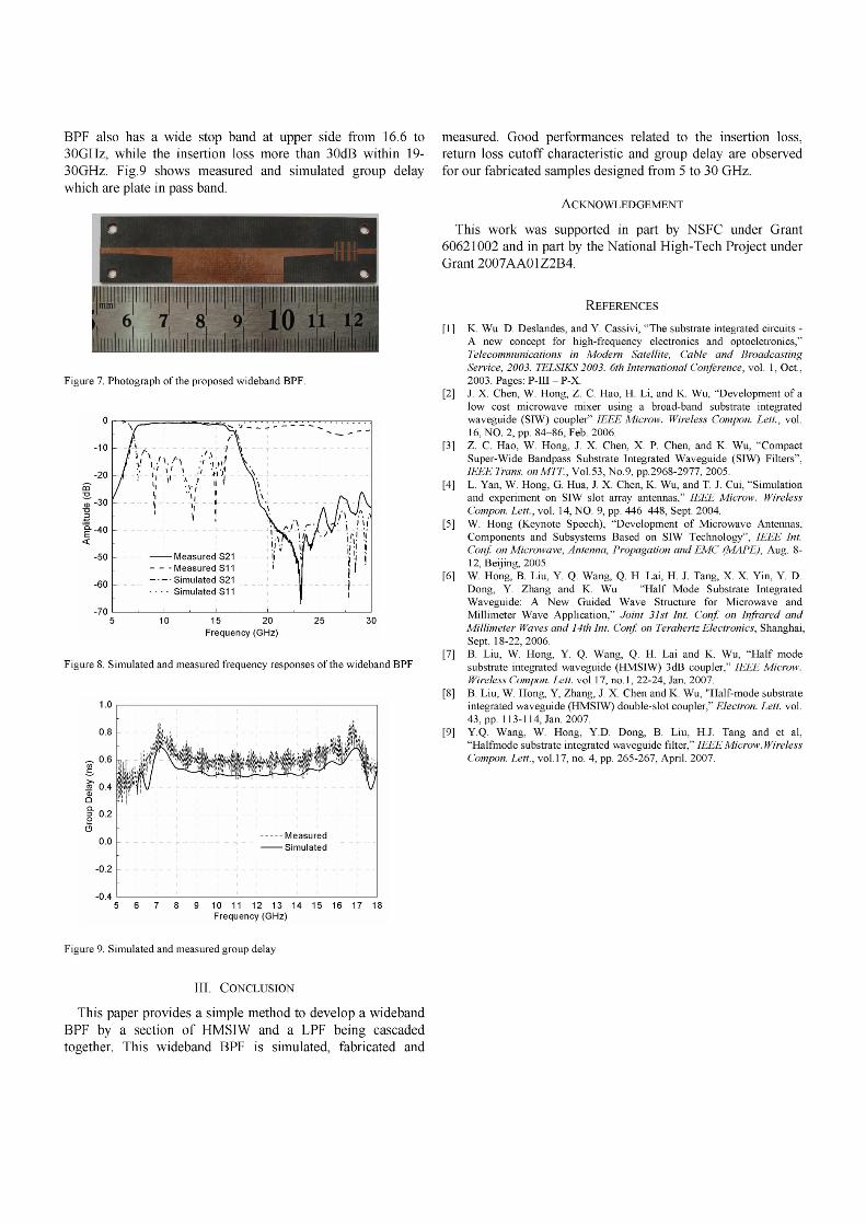
BPF also has a wide stop band at upper side from 16.6 to30GHz, while the insertion loss more than 30dB within 19-30GHz. Fig.9 shows measured and simulated group delaywhich are plate in pass band.
Figure 7. Photograph of the proposed wideband BPF.
O0 ...........
-40
Frequency (GHz)
Figure 8. Simulated and measured frequency responses of the wideband BPF
1 .0
0.8
0.6U)
X 0.4a)
= 0.20
0.0
-0.2
-0.4 L5 6 7 8 9 10 11 12 13 14 15 16 17
Frequency (GHz)
measured. Good performances related to the insertion loss,return loss cutoff characteristic and group delay are observedfor our fabricated samples designed from 5 to 30 GHz.
ACKNOWLEDGEMENT
This work was supported in part by NSFC under Grant60621002 and in part by the National High-Tech Project underGrant 2007AAOlZ2B4.
REFERENCES
[1] K. Wu. D. Deslandes, and Y. Cassivi, "The substrate integrated circuits -A new concept for high-frequency electronics and optoeletronics,"Telecommunications in Modern Satellite, Cable and BroadcastingService, 2003. TELSIKS 2003. 6th International Conference, vol. 1, Oct.,2003. Pages: P-Ill - P-X.
[2] J. X. Chen, W. Hong, Z. C. Hao, H. Li, and K. Wu, "Development of alow cost microwave mixer using a broad-band substrate integratedwaveguide (SIW) coupler" IEEE Microw. Wireless Compon. Lett., vol.16, NO. 2, pp. 84-86, Feb. 2006.
[3] Z. C. Hao, W. Hong, J. X. Chen, X. P. Chen, and K. Wu, "CompactSuper-Wide Bandpass Substrate Integrated Waveguide (SIW) Filters",IEEE Trans. on WT., Vol.53, No.9, pp.2968-2977, 2005.
[4] L. Yan, W. Hong, G. Hua, J. X. Chen, K. Wu, and T. J. Cui, "Simulationand experiment on SIW slot array antennas," IEEE Microw. WirelessCompon. Lett., vol. 14, NO. 9, pp. 446-448, Sept. 2004.
[5] W. Hong (Keynote Speech), "Development of Microwave Antennas,Components and Subsystems Based on SIW Technology", IEEE Int.Conf on Microwave, Antenna, Propagation and EMC (MAPE), Aug. 8-12, Beijing, 2005.
[6] W. Hong, B. Liu, Y. Q. Wang, Q. H. Lai, H. J. Tang, X. X. Yin, Y. D.Dong, Y. Zhang and K. Wu "Half Mode Substrate IntegratedWaveguide: A New Guided Wave Structure for Microwave andMillimeter Wave Application," Joint 31st Int. Conf on Infrared andMillimeter Waves and 14th Int. Conf on Terahertz Electronics, Shanghai,Sept. 18-22, 2006.
[7] B. Liu, W. Hong, Y. Q. Wang, Q. H. Lai and K. Wu, "Half modesubstrate integrated waveguide (HMSIW) 3dB coupler," IEEE Microw.Wireless Compon. Lett. vol. 17, no. 1, 22-24, Jan. 2007.
[8] B. Liu, W. Hong, Y, Zhang, J. X. Chen and K. Wu, "Half-mode substrateintegrated waveguide (HMSIW) double-slot coupler," Electron. Lett. vol.43, pp. 113-114, Jan. 2007.
[9] Y.Q. Wang, W. Hong, Y.D. Dong, B. Liu, H.J. Tang and et al,"Halfmode substrate integrated waveguide filter," IEEE Microw. WirelessCompon. Lett., vol. 17, no. 4, pp. 265-267, April. 2007.
Figure 9. Simulated and measured group delay
111. CONCLUSION
This paper provides a simple method to develop a widebandBPF by a section of HIMSIW and a LPF being cascadedtogether. This wideband BPF is simulated, fabricated and


![-10 0 · Design IIR Bandpass Filters In this post, I present a method to design Butterworth IIR bandpass filters. My previous post [1] covered lowpass IIR filter design, and provided](https://static.documents.pub/doc/80x56/5ebb71a95c880514701dd82d/10-0-design-iir-bandpass-filters-in-this-post-i-present-a-method-to-design-butterworth.jpg)


