Paper–A ZigBee and Sip-Based Smart Home System Design and Implementation A ZigBee and Sip-Based Smart Home System Design and Implementation https://doi.org/10.3991/ijoe.v13i01.6258 Jian. Luo Zhejiang Technical Institute of Economics, Hangzhou, China [email protected]Abstract—This investigation presents a ZigBee and Sip based smart home system (ZSS) that automates home-service operations and remote access. The ZSS home system comprises five subsystems, namely home automation net- work, home IP network, home gateway, remote access unit, and cloud service unit. The home automation network is a wireless sensor network, responsible to sample sensors data and control actuators by ZigBee instructions. Security sys- tem adopts IP network technology to transmit videos from IP cameras to remote units. A home gateway middleware is designed to extract atomic service pro- vided by a single device, and then customize service rules which can meet vari- able user demands. Peer to Peer transparent data channels between remote mo- bile phones and home devices are set up by Sip framework to overcome con- nection issues due to network address translation and dynamic public IP ad- dress. A novel data stream algorithm named GCOKDE is exploited to get prob- ability density distribution of environmental parameters which can be used for the condition value of service rule. At the end, this study constructs a prototype to reveal the procedure of realization. Index Terms—ZSS Home System, Home Gateway, Customized Service Rule, P2P, Data Mining 1 Introduction In recent years, research achievements and application hotspots in the field of smart homes continue to emerge, mainly due to the rapid progress of the Internet of Things (IoT), mobile Internet, cloud computing, big data and other information technologies. Providing environment awareness and remote control services, monitoring the home environment with intelligent algorithms, and maximizing the comfort and satisfaction of occupants based on ubiquitous computing are the main tasks of the development of smart home systems [1]. Of these, environment awareness is an indispensable precon- dition for home intelligence. It takes in features of the environment and behavioural habits of occupants in many ways and assists users in customizing home intelligence 42 http://www.i-joe.org
Transcript
Paper–A ZigBee and Sip-Based Smart Home System Design and Implementation
A ZigBee and Sip-Based Smart Home System Design and Implementation
https://doi.org/10.3991/ijoe.v13i01.6258
Jian. Luo Zhejiang Technical Institute of Economics, Hangzhou, China
Abstract—This investigation presents a ZigBee and Sip based smart home system (ZSS) that automates home-service operations and remote access. The ZSS home system comprises five subsystems, namely home automation net-work, home IP network, home gateway, remote access unit, and cloud service unit. The home automation network is a wireless sensor network, responsible to sample sensors data and control actuators by ZigBee instructions. Security sys-tem adopts IP network technology to transmit videos from IP cameras to remote units. A home gateway middleware is designed to extract atomic service pro-vided by a single device, and then customize service rules which can meet vari-able user demands. Peer to Peer transparent data channels between remote mo-bile phones and home devices are set up by Sip framework to overcome con-nection issues due to network address translation and dynamic public IP ad-dress. A novel data stream algorithm named GCOKDE is exploited to get prob-ability density distribution of environmental parameters which can be used for the condition value of service rule. At the end, this study constructs a prototype to reveal the procedure of realization.
Index Terms—ZSS Home System, Home Gateway, Customized Service Rule, P2P, Data Mining
1 Introduction
In recent years, research achievements and application hotspots in the field of smart homes continue to emerge, mainly due to the rapid progress of the Internet of Things (IoT), mobile Internet, cloud computing, big data and other information technologies. Providing environment awareness and remote control services, monitoring the home environment with intelligent algorithms, and maximizing the comfort and satisfaction of occupants based on ubiquitous computing are the main tasks of the development of smart home systems [1]. Of these, environment awareness is an indispensable precon-dition for home intelligence. It takes in features of the environment and behavioural habits of occupants in many ways and assists users in customizing home intelligence
42 http://www.i-joe.org
Paper–A ZigBee and Sip-Based Smart Home System Design and Implementation
services. This is achieved by identifying and collecting status parameters and au-dio/video signals generated through the interaction between the user and the residential intelligent devices such as sensors, controllers and IP cameras. Meanwhile, with the rapid expansion of Internet infrastructure and increasing popularity of smartphones, it is necessary for smart home systems to allow users to remotely access multiple intelli-gent devices in the home network and stay informed as to what is happening at home[2].
With short transmission distance and low-power consumption, a wireless sensor network (WSN) can effectively converge sensor nodes to collect data, and actuator nodes to control lighting switches and household appliances, forming a home automa-tion network. Compared with wired networks, a wireless ad-hoc network is scalable and more suitable for home use since knob-and-tube wiring can be avoided. Currently, mainstream WSN protocols include ZigBee and 6LoWPAN, etc [3, 4]. Both of them have some merit and demerit respectively.
Remote access technology allows peer-to-peer data exchange (P2P) via the Internet and home networks whenever and wherever people want it. Reachability, addressabil-ity and security are the major challenges currently facing remote access [2]. Due to the scarcity of IPV4 addresses, most ISPs allocate only one public IP address to each home system, so only local private networks can be built within the home system and IP devices within that system access the Internet by NAT on a home gateway [5]. For the sake of safety, NAT limits direct access to IP devices within the intranet from the out-side. Even if remote access can overcome the reachability limitations of NAT and allow forwarding of external datagrams to corresponding devices in the private net-work, the home gateways' public IP addresses allocated by ISPs are usually dynamic. This means remote access needs appropriate strategies for effectively identifying these dynamic addresses. The connection between private home networks and the Internet also means there is a vulnerability to public network hackers and virus attacks; there-fore the ZSS home system must pass robust authentication and authorization measures, and ensure there is no disclosure of user privacy.
Each device in the ZSS home system has a single function. From a practical stand-point, it is necessary to combine the atomic services of these devices and provide per-sonalized services to users based on specific rules. For example, for a security alarm, the active infrared sensor in its monitoring status will trigger an alarm when it detects an intrusion; upon receiving notification of the alarm on a smartphone, the user may access the video function and execute remote monitoring, while the system will auto-matically activate auxiliary devices in the field to provide variable responses. The combination of device functions resulting in a rule-based service that makes physical devices transparent to users, helps users understand the systems’ functions at the se-mantic level, and facilitates ease of end-user operation. In addition, based on data streams of environment parameters uploaded from the ZSS home system [6], the cloud data mining algorithm, taking advantage of grid and clustering, will evaluate the prob-ability density distribution of all parameters in real-time [7], and assist users in under-standing the dynamic changes of their home environment, while intelligently activating the particular service rules.
The remainder of the paper is organized as follows: Section II discusses the relevant protocol standards, especially comparing the similarities and differences between ZigBee Protocol and 6LoWPAN Protocol. Section III shows system architecture and corresponding functions. Section IV describes the technical detail of building ZigBee network in the ZSS home system. Online and history video processing for security monitoring is listed in Section V. A lightweight embedded middleware, which is the
iJOE ‒ Vol. 13, No. 1, 2017 43
Paper–A ZigBee and Sip-Based Smart Home System Design and Implementation
control center of ZSS home system and allows users to customize service rules, is described in Section VI. The steps of establishing a P2P data channel between remote mobile phones and home devices are illustrated in Section VII. To get the condition value of a condition-based service rule, Section VIII presents a real-time data stream kernel density estimation algorithm named GCOKDE. In Section IX, the implementa-tion process of ZSS home system is clarified by a prototype platform. Finally, the con-clusions and some suggestions for future work are given in Section X.
2 Relevant Protocol Standards
The design and implementation of ZSS home system is primarily based on ZigBee Protocol and Sip Protocol. Developed and recommended by the ZigBee Alliance, ZigBee Protocol is a low-speed WPAN protocol established on the physical layer and the MAC layer compliant with IEEE802.15.4, and with a maximum data transfer rate of 250kbps. Its node signal can be transmitted up to 100 meters. Based on AES 128-bit security encryption algorithm [3], the ZigBee network is soundly secured.The new ZigBee3.0 Standard has removed the problematic connection between the mainstream application layer protocols experienced by its predecessor, but it still fails to solve the issue of cross-protocol interconnection[8]. It is incompatible with the TCP/IP Protocol, so datagrams that need to be transmitted between devices working under different protocols must be forwarded via a home gate. Another WPAN protocol is 6LoWPAN, or LOW-power wireless Personal Area Network IPV6 protocol. It has also established on the basis of IEEE802.15.4. Compared to the ZigBee Protocol, its greatest advantage is that it can be seamlessly integrated with other IP systems. However, its integration is a bit costly at present. Firstly, RFC2460 defines 1280 bytes as IPv6's Maximum Transmission Unit (MTU) [9], while IEEE802.15.4 defines 127 bytes as its Maximum Frame Size. So, an Adaptation Layer between the Network Layer and the MAC Layer must be created by IPv6's related protocol stacks for fragmentation and reorganization of datagrams, enabling IPv6 datagrams to be transmitted over networks working under IEEE 802.15.4. Secondly, in light of the considerable investment required and the necessity of keeping day-to-day business uninterrupted, global transition from the current IPV4-based Internet infrastructure to IPV6-compatible Internet infrastructure is an on-going process expected to take a long time. In an actual application scenario, the connection between the 6LoWPAN subnet and an IPV4-based network requires the utilization of access technologies to realize the conversion between IPV4 and IPV6 protocols [10]. In light of the technical characteristics, official support, recognition from the third party manufacturers and market acceptance of ZigBee and 6LoWPAN protocols, the ZigBee protocol has been selected as the basic protocol for the ZSS home system. In addition an application layer gateway allowing interoperability be-tween ZigBee equipment and IP equipment has been designed and showcased.
Sip Protocol is an IP-based multimedia audio and video signalling protocol [11]. Similar to the http Protocol, Sip encapsulates the text of control information in the message header field, and achieves establishment/release calls with client/server archi-tecture and a three-way handshake mechanism (Request - Response - Confirm). Com-bining Sip, Stun, Ice and other protocols [12, 13], P2P connection channels over heter-ogeneous networks can be established to realize reachability, while also addressability and security for remote access.
44 http://www.i-joe.org
Paper–A ZigBee and Sip-Based Smart Home System Design and Implementation
3 System Architecture
The ZSS home system consists of a home automation network, home IP network, home gateway, remote access unit and cloud services unit, as shown in Fig. 1. There are two ways for users to communicate with the system from their smartphones: (1) Directly access the home IP network through the home WiFi, or (2) Access the system through an outside network connected to Internet. For example, a 3G/4G mobile net-work.
Fig. 1. System Architecture Overview
The home automation network collectively controls and monitors multiple low-speed ZigBee devices, such as lighting, smoke/infrared/magnetometer/gas sensors, HVAC, and household appliances, etc. Control is achieved by manual operation by the user or automatic operation of the system. In manual control mode, the user can direct-ly control actuators in the system through a smartphone, and perform operations such as turning on/off a specified device, adjusting signal strength, etc. For automatic con-trol, the control logic is determined by the service rules predefined by the system. It allows condition control, timing control and periodic control, bringing convenience and comfort to users. The monitoring function collects data of environment parameters through sensors in the network and sends it to the user's smartphone for browsing, or uploads it to a cloud data service unit for data mining, which in turn helps trigger the automatic execution of condition-based predetermined service rules. Due to reliable household power supply and the potential demand for data communication between home devices, most ZigBee devices in the system are active full-function devices, and the ZigBee network uses mesh topology.
The high-speed IP broadband network allows easy and fast access of WiFi-supported devices, such as a smartphone, PDA, computer, IP camera, etc. It also satis-fies the big data throughput of multimedia applications, and fulfills tasks like security video monitoring and playback.
Home gateway connects various devices in the ZSS home system and bridges the ZSS home system to the outside world. Its functions include:
iJOE ‒ Vol. 13, No. 1, 2017 45
Paper–A ZigBee and Sip-Based Smart Home System Design and Implementation
1. A wireless AP with routing capability, capable of being connected to an existing home IP network or setting up an IP network itself, and providing access to the In-ternet;
2. Gateway (coordinator) for the ZigBee network, for establishing a ZigBee device network within the designated area;
3. Providing interoperability between a heterogeneous WiFi network and the ZigBee network and carrying out conversion of commands and data between the TCP/IP protocol and the ZigBee protocol at the application layer;
4. In consideration of data security and limited resource of cloud services, during a process of remote access, heterogeneous remote access unit, serving as the Sip user agent, not only assists in securing reliable P2P communication between smartphone in 3G/4G mobile network or WIFI network and devices in the home network, but also avoids data transfer in cloud servers.
5. Establishing a unified middleware platform for smart home device management, and abstracting atomic services provided by the devices, monitoring requests from remote mobile terminals and distributing services based on customized service rules.
The home gateway and remote access unit in the heterogeneous network require support from public cloud services to realize the system’s functions. The reasons are shown below:
1. Setup and release of Sip calls rely on a Sip proxy, register and location services; Stun/Turn services support the establishment of data channels and media channels for communication [14]; and Web services provide access to the back-end data-base. To access home gateway and remote access unit, all these services have to be set up in the cloud.
2. Compared with the overall investment in a smart home system, it is inadvisable to set up high performance data analysis servers and media servers in a home net-work. It is an economic choice to make full use of the powerful computing and da-ta handling capacities of public cloud services, and enable users to share cloud re-sources on the premise that their privacy is ensured.
4 Home Automation Network
The home automation network is based on ZigBee Alliance standards and the Z-Stack protocol stack [15, 16]. The process of ZigBee network construction, node ac-cess to the network and network management are described in detail in this section.
4.1 Forming the ZigBee Network
In forming the ZigBee network, a ZigBee coordinator integrated in the home gate-way completes network initialization by sending a NLME-NETWORK-FORMATION.request primitive, selecting a Personal Area Network Identifier (PAN_id) randomly, and setting the coordinator network address to 0X0000. PAN_id
46 http://www.i-joe.org
Paper–A ZigBee and Sip-Based Smart Home System Design and Implementation
and other process parameters are stored in the Non-Volatile memory (NV) of the coor-dinator. Recovery of factory settings is impossible unless pressing the reset key of home gateway. Therefore, if a power failure occurs in the coordinator causing it to restart, the above parameters will be read directly from the NV for network set-up. This can accelerate network set-up and speed up the process for the devices to rejoin the network. Given the ad-hoc capability of the ZigBee network, to prevent accident joining of neighbors’ devices, the NLME-PermitJoining.request (0x00) primitive is sent to the coordinator and the router to prevent unauthorized access of new devices to prohibited networks without affecting those already connected to the network before.
4.2 Joining the ZigBee Network
The joining device sends the NLME-NETWORK-DISCOVERY.request primitive to scan alternative channels, and then collect technical parameters of nearby networks in the returned beacon frame, including channel identifier, PAN_id, and permit joining flag, etc. If there are any networks that can be accessed, call NLME-JOIN.request primitive to join the network. The process includes searching for a suitable parent node in the neighbor table at the network layer and sending MLME-ASSOCIATE.request primitive to establish a connection at the MAC layer. After successfully joining the network, refresh the neighbor table of parent node and child node, update network parameters in the Network Information Base (NIB), and store the PAN_id and other parameters distributed by the network in NV. For network outages due to power-off recovery, displacement, or environment change (becoming an orphan node) of network devices, the strategy for reconnection is to use the network status monitoring function nwk_Status provided by the protocol stack. If NWK_ERROR_ASSOC_ CNF_DENIED shows disconnected, call primitives like NLME-REJOIN.request or NLME-JOIN.request through orphaning to restart connection. Rejoining network is not limited by network access restriction, unless the NV of the device was reset to factory settings.
4.3 Managing the ZigBee Network
The Monitor and Test interface (MT) of the protocol stack supports transmission of network management commands and application data through the RS232 serial port between the host and the coordinator within the home gateway. Management com-mands are responsible for reading information at different levels of the protocol stack, and for configuring the networks and devices. The application data follows the network and device operation standards as defined by ZigBee Home Automation Public Appli-cation Profile [15]. The MT commands, which are sent by the home gateway to the coordinator and parsed by the serial port callback function MT_UartProcess ZToolData, will generate the CMD_SERIAL_MSG message. The message is extracted from the event execution function at the MT layer subject to protocol stack polling, and it calls multiple command process functions by function pointers to parse and execute specified commands. Responses to command requests are classified into two kinds: synchronous responses, namely instantaneous return of the results, and asynchronous response, by subscribing to a callback function that returns the results. Data packets sent by the node to the coordinator include an asynchronous response to the request command and uploaded application data. On receiving the data packets, the coordina-tor uploads them to the home gateway after packing them.
iJOE ‒ Vol. 13, No. 1, 2017 47
Paper–A ZigBee and Sip-Based Smart Home System Design and Implementation
5 Security Monitoring
In Fig. 1, there are two security application scenarios in the ZSS home system:
1. Online accessing of real-time video recorded by in-house IP cameras through re-mote/indoor devices like a smartphone;
2. Online browsing of archived security videos stored in the cloud media database through remote/indoor devices like a smartphone.
In scenario 1, a standard media stream is acquired via a RTSP message from IP camera [17]; RTSP messages are classified into request commands and response com-mands, and signaling methods include DESCRIBE, SETUP, PLAY and TEARDOWN. RTSP message exchange between the mobile phone and the IP camera completes pa-rameters transmission and controls the start and stop of media stream transmission. Media stream is encapsulated in RTP format and transmitted via UDP and multicast methods [18]. The RTSP communication process is shown in Fig. 2.
Fig. 2. RTSP Communication process
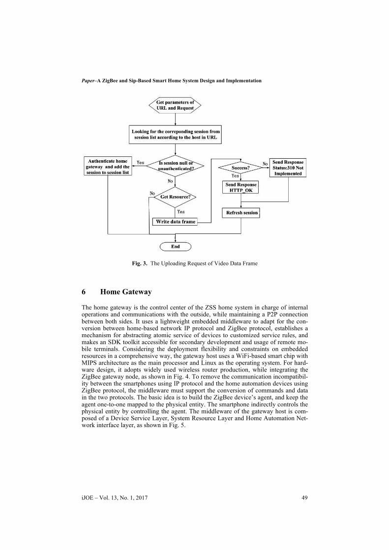
In scenario 2, the smartphone’s query of videos from the cloud media database is in principle identical with that in scenario 1 – acquiring and controlling the video stream from the media database by RTSP messages. So the procedure is not repeated here. The process of uploading video to the media database is completed by HTTP request and response. Once the home gateway receives an alarm from the device, it will re-trieve whether there is action associated with the alarm and whether the customized service rules require the video to be uploaded to the cloud or not. If yes, the system will send an Http request to a web service, and the web service will convert the Http request through FastCGI, and handle the request accordingly. The three kinds of Http requests include requesting video upload, requesting video data frame upload, and requesting video upload termination. Processing flow of video data frame uploading request is shown in Fig 3.
48 http://www.i-joe.org
Paper–A ZigBee and Sip-Based Smart Home System Design and Implementation
Fig. 3. The Uploading Request of Video Data Frame
6 Home Gateway
The home gateway is the control center of the ZSS home system in charge of internal operations and communications with the outside, while maintaining a P2P connection between both sides. It uses a lightweight embedded middleware to adapt for the con-version between home-based network IP protocol and ZigBee protocol, establishes a mechanism for abstracting atomic service of devices to customized service rules, and makes an SDK toolkit accessible for secondary development and usage of remote mo-bile terminals. Considering the deployment flexibility and constraints on embedded resources in a comprehensive way, the gateway host uses a WiFi-based smart chip with MIPS architecture as the main processor and Linux as the operating system. For hard-ware design, it adopts widely used wireless router production, while integrating the ZigBee gateway node, as shown in Fig. 4. To remove the communication incompatibil-ity between the smartphones using IP protocol and the home automation devices using ZigBee protocol, the middleware must support the conversion of commands and data in the two protocols. The basic idea is to build the ZigBee device’s agent, and keep the agent one-to-one mapped to the physical entity. The smartphone indirectly controls the physical entity by controlling the agent. The middleware of the gateway host is com-posed of a Device Service Layer, System Resource Layer and Home Automation Net-work interface layer, as shown in Fig. 5.
iJOE ‒ Vol. 13, No. 1, 2017 49
Paper–A ZigBee and Sip-Based Smart Home System Design and Implementation
Fig. 4. The Hardware Principle of Home Gateway Host
Fig. 5. The Middleware Framework of Gateway Host
50 http://www.i-joe.org
Paper–A ZigBee and Sip-Based Smart Home System Design and Implementation
6.1 The Interface Layer of Home Automation Network
The TCPZigBeeRawDataServer component is responsible for receiving/sending MT command frames from/to the ZigBee network coordinator via a RS232 serial port. This component provides the ability for sending/receiving binary byte streams, data checks and buffering functions, and it is connected with the core Zport module. The Zport module parses the MT frame in a binary byte stream from the TCPZigBeeRawDa-taServer component, de-serializes it into program-friendly class format commands and adds it to Class CMD Processing Unit for later execution; similarly, it serializes class format commands in the Class CMD Release Unit into MT frames in binary byte streams before they are sent to the coordinator by the TCPZigBeeRawDataServer component. Meanwhile, the Zport module can enable connection/disconnection to the ZigBee network. This function is used to connect to the ZigBee network and maintain the heartbeat of the ZigBee network after connection, or to disconnect the ZigBee network.
6.2 System Resource Layer
The system resource layer maintains the resources to be invoked and configured by the system, which includes the Configuration Center, Device Manager, Rule Center, and other relevant resources. The Configuration Center permanently stores the service rules in XML format, the ZigBee device agent, IP devices, region parameters and other configured system parameters. The ZigBee device agent stores the MAC address, net-work short address, endpoint number, clusterId, device type, device sub-type, availabil-ity, region data, online flags and other fields which are one-to-one mapped to the ZigBee device by a fixed MAC address. Please see the examples below for reference: <object id="00124B000218ED526F" nwkaddr="47588" endpoint="111" cluster="6" type="OnOffLight" subtype="0" enabled="true" region="1# warehouse” icon="droplight_icon.png" LQI="0" battery="0" online="1">light</object>
A gateway host allows for activating the configuration mode when the network ac-cess mode is enabled. The Gateway Host will receive message commands from mobile phones in the TLV format, and search the ZigBee network for all ZigBee devices with the RF function activated thereby enabling the ability to search, retrieve, update and/or remove ZigBee devices. The Configuration Service component allows for the configu-ration of user application information of ZigBee device agents in order to augment the description of ZigBee devices. After configuring the settings and logging out from the configuration mode, the ZigBee device agent is established. All mobile phone-based operations will then be forwarded by the Service Cluster, through standard IP sockets, and to the ZigBee device agent enabling control of the ZigBee device. Vice versa, the data uploaded by ZigBee device is also transmitted through the Service Cluster after locating ZigBee device agent to mobile phones. Furthermore, it must be noted that each IP device application has its own IP address and socket number that is registered in the Device Manager and used in the establishment of service rules.
6.3 Customized Service Rule
The Device Service component controlled by the mobile phone performs read-ing/writing (R/W) operations on ZigBee devices, and only a single device can be oper-ated immediately. Many tasks of the ZSS home system involve simultaneous opera-
iJOE ‒ Vol. 13, No. 1, 2017 51
Paper–A ZigBee and Sip-Based Smart Home System Design and Implementation
tions and pre-conditioned execution of multiple devices. A customized service rule can be preset and executed just like pressing the "all in one key". The service rule consists of one or more conditions and optional action lists. In a Scene Rule, instant actions on multiple devices activated by clicking can be set; for a Senior Rule, conditions of logic, timing and devices are added in scene rules or newly established rules, thus meeting multiple application requirements. The following example describes a timing rule based in XML syntax format:
<rule id="C5E72714-D270-0001-16A1-16DBB2301AA3" description="go on
According to the rule "go on working", the system executes the action at 22:35 Oc-tober 30th, 2016, turns off the device coded "00124B000220F9946F" and turns on the device coded "00124B000220F7536F". A scenes cluster of device groups is defined in ZCL [19], but it only supports the instant combined operation of devices within the group and no control conditions are set. As a result, to realize the above "go on work-ing" rule, the Rule Service component inside the middleware facilitates two functions:
1. When action objects in a rule are multiple ZigBee devices, the system converts the actions into ZCL commands before it is sent to any ZigBee device group. This in-cludes the command of adding a group and adding a scene in the initialization pro-cess, and scene execution command after the timing precondition is met etc. It should be made clear that the middleware scene refers to the scene rule defined by the user, while the ZCL scene cluster provides operation commands for multiple devices. The two are different in their meanings.
2. Trigger the timing rule by the timing task mechanism in the Linux system of the gateway host.
To initialize gateway host, the system calls for Configuration Center information, in-itializes services, the Class CMD Release/Processing Unit and the Zport module in sequence; and then the Listener Service component will listen to the connection from the smartphone by the TCP Socket. Once the request for connection arrives, the inter-action between the mobile phone and the system starts. The Application CMD Service component parses the control command sent by mobile phone in XML format, and returns its response after finishing the operation. Control commands include read-ing/writing device, reading/writing configuration, executing single action and execut-ing actions in a rule.
52 http://www.i-joe.org
Paper–A ZigBee and Sip-Based Smart Home System Design and Implementation
7 P2P Connection
Each IP device registered with the Device Manager has its own IP address and sock-et number. All agents of ZigBee devices also have a universal IP address and socket number. Establishment of multiple P2P transparent transmission channels between the agent and the remote mobile phone is based on task division and collaboration between Sip, Sdp, Ice, Stun and Turn protocols [20]. Fig. 6 shows a more complex situation in which the gateway host and the remote phone are in different NATs. In this scenario, the mobile phone may be in a remote WiFi network, and there is cascade connection between multiple gateway hosts in the home network. It is similar to the case in which a mobile phone operates in a 3G/4G network. So, that scenario will not be repeated here.
Fig. 6 Establishment Process of the P2P channel
1. Collecting the transmission address: the session initiator collects a set of local ad-dresses (IP and socket) and public addresses (provided by Stun and Turn). The ad-dress provided by Stun is the extranet address of the session initiator; the address from Turn is the relay address used when a direct P2P transfer fails.
2. Initiating Stun and identifying address priority: the session initiator initializes the Stun service in a local transmission address, and determines priority of each trans-mission address based on their traffic flows.
3. Generating and sending the Sip signal of the invite message: the session initiator and recipient have been registered and located in the Sip service in advance, and a correlation has been established already (see Section VIII: System Implementation). The header field of the Sip signal contains a list of reachable addresses for the ses-sion recipient based on correlated information; Sdp contains a set of transmission addresses collected in step 1. As soon as the above invite message for the Sip sig-nal is created, it will be sent and call the session recipient.
4. Generating and returning an ack message, and establishing a transparent transmis-sion channel: when the recipient receives a call, repeat step 1 and step 2. Then send an ack message, which includes the list of its transmission addresses, to the session initiator, so that both sides are aware of each other’s candidate transmission ad-dresses. Ice negotiation then starts. Addresses of the two parties are matched one by one. Both send Stun Binding requests to each other to check the connectivity and determine the optimal address pairing. Stun Binding requests are sent asyn-chronously and bidirectionally, and have to achieve the four-handshake procedure in order to overcome NAT’s restricted access to data packets from unregistered public network addresses. This ensures reachability.
To preserve resources, NAT will automatically close channel(s) that are unused for a certain period of time [5], and the home network public IP provided by the ISP is gen-erally dynamic. Because of this, both sides should send heartbeat packets to each other regularly after the establishment of connected channels to ensure the efficient address-ing of transparent transmission. Once a heartbeat packet reception times out, a P2P connection must be re-established to ensure real-time performance and reliability of data transmission.
iJOE ‒ Vol. 13, No. 1, 2017 53
Paper–A ZigBee and Sip-Based Smart Home System Design and Implementation
Fig. 6. The Network Topology of P2P connection
8 Data Mining And Simulation
The sampled data uploaded to the cloud data service center in real time is chronologically arriving, quickly changing, massive and potentially infinite, and matches the basic characteristics of data streams [6]. In the fundamental process of feedback control, sensors collect the environmental parameters of the field, and once the threshold is met the actuator is activated to ensure the stability of these parameters. To overcome transient disturbance error, and reflect the environment parameters of the data stream over time, it is necessary for the ZSS home system to obtain probability density function (PDF) of environment parameters within a fixed window period, and take the mean of PDF as an independent variable for triggering condition-based service rules. For example, gas sensors can collect PM2.5 sample on a regular basis, and ac-cordingly the action and termination of an air purifier can be controlled intelligently based on the mean of samples taken within a time window.
The ZSS home system exploited a real-time data stream kernel density estimation algorithm GCOKDE combining grid, clustering, and optimization technology [7]. The algorithm uses online/offline two-stage architecture as shown in Fig. 7. The online stage continues to maintain non-stop data streams and store them in a FIFO queue. The head data and tail data of the queue are mapped to corresponding grids to enable updat-ing of the clustering feature (CF) of the grids. Statistical information from the original data is stored in the grid sextuple. Grid clustering based on weighted K-means is per-formed at the offline stage, and the number of the grids involved in the kernel density estimation is reduced to the number of clustering kernels. The obtained clustering is corrected according to optimization strategies to ensure the local minimum kernel merging error, thereby acquiring clustering optimized kernel. This allows collection of the data stream kernel density estimation at the query points, displays system environ-mental parameters automatically triggering service rules.
54 http://www.i-joe.org
Paper–A ZigBee and Sip-Based Smart Home System Design and Implementation
!
Z
Time Queue
Data Stream
Tail Head
! .. ..
....
...! !
! !
Add Remove
Online Stage
Abandon
Data Grid
! .. ..
....
...
! . . .
Offline Stage
Fig. 7. The Framework of GCOKDE
A simulation of 8 mixed Gauss distributions in Table I by GCOKDE is shown in Fig. 8. It can be seen that the algorithm is of high quality. The mean of real-time PM2.5, temperature, and humidity within a time window, which are calculated with this algo-rithm and displayed on a mobile phone APP interface, is shown in Fig. 9.
Paper–A ZigBee and Sip-Based Smart Home System Design and Implementation
Fig. 9. PM2.5 by GCOKDE
9 System Implementation
To clarify the implementation process of the ZSS home system, a prototype platform is set up in Fig. 10.
Fig. 10. System Prototype
56 http://www.i-joe.org
Paper–A ZigBee and Sip-Based Smart Home System Design and Implementation
The main operation steps are shown below:
1. When the gateway host starts for the first time, the identity certificate is sent to the cloud server for verification. The login account and the security key are then gen-erated.
2. As a user agent, the gateway host is located by Sip location server through a Sip register server every time the gateway host starts. The Sip server requires the gate-way host to perform digest access authentication scheme and ensure secure access. The ZigBee application and IP application of the gateway host listen to outside connection requests at their individual socket.
3. First-time users need to register a cloud service account by sending an http request with their phone.
4. Similar to step 2, every time a user logs in with a cellphone, serving as a user agent, it will be located by Sip location server through a Sip register server. The Sip server requires the mobile phone to perform digest access authentication scheme and ensure secure access.
5. LAN broadcast establishes a correlation between the mobile phone and the gate-way. A many-to-many relationship between the mobile phone, the host and the us-er is stored in the cloud database.
6. If communication between the mobile phone and the gateway host is needed, query the cloud database to obtain the corresponding gateway host identifier, and receive the target address from the Sip location server. Then a session with the gateway host is established through the relay of the Sip server. The two sides negotiate with each other by Ice protocol, and search for and establish an optimal P2P data chan-nel for transparent transmission.
7. The mobile phone calls the Application CMD Service at the corresponding socket of the gateway host, and monitors areas under the host area’s surveillance. The two are connected in a many-to-many configuration.
For the prototype platform in Fig. 10, the ZigBee actuators are simple switches to control the lights and fans; the infrared/gas sensor serves as a ZigBee node. Together with the coordinator embedded in the home gateway, they constitute a ZigBee wireless network. The IP camera and the home gateway are connected via a WiFi network. Fig. 11 shows the devices in the area named “Simulation” on the phone’s APP interface. Each device can be operated individually. In the picture, two lights are on. Fig. 12 is a scene mode in which the user can turn on/off a set of predefined devices by pressing an “all in one key” according to customized service rules.
The infrared alarm in security monitoring is based on predefined service rules, as shown in Fig. 13. On detecting any intrusion, the infrared sensor will trigger service rules, alert the mobile phone (Fig. 14), activate the auxiliary devices in the field, and upload video to the cloud media server for later review (Fig. 15).
iJOE ‒ Vol. 13, No. 1, 2017 57
Paper–A ZigBee and Sip-Based Smart Home System Design and Implementation
Fig. 11. Devices in Areas
Fig. 12. System Scene
Fig. 13. Alarm rule
Fig. 14. APP Alarm
Fig. 15. Alarm Video
58 http://www.i-joe.org
Paper–A ZigBee and Sip-Based Smart Home System Design and Implementation
10 Conclusion
The ZSS home system integrates a number of technologies, such as wireless com-munication, middleware, data mining, streaming media, and cloud service, etc. It can operate home automation devices and security monitoring remotely by customized service rules. During the writing of this paper, the ZSS home system has run in a number of smart communities successfully. In the future, we will concentrate our efforts on two areas. One is to update ZigBee protocol to version 3.0, which can en-hance the interoperability with third party manufacturers. The other is to adopt more data mining and artificial intelligence algorithms, which can provide a better user experience.
11 References
1. R. A.Muhammad, B.I.R. Mamun and A.M.A. Mohd, “A Review of Smart Homes—Past, Present, and Future”, IEEE Transactions on Systems, Man, and Cybernetics—Part C: APPLICATIONS AND REVIEWS, vol. 42, no. 6, 2012,pp. 1190-1203. https://doi.org/10.1109/TSMCC.2012.2189204
2. P. Belimpasakis and V. Stirbu, “A survey of techniques for remote access to home net-works and resources”, Multimedia Tools and Applications, vol. 70, no. 3,2014, pp. 1899-1939. https://doi.org/10.1007/s11042-012-1221-y
4. Internet Engineering Task Force (IETF), “IPv6 over Low power WPAN (6lowpan)”, https://datatracker.ietf.org/wg/6lowpan/documents/, 2012.
5. Internet Engineering Task Force (IETF), “The IP Network Address Translator (NAT)”, https://www.ietf.org/rfc/rfc1631.txt, 1994.
6. P. Domingos and G. Hulten, “Catching up with the data: Research issues in mining data streams”, Workshop on Research Issues in Data Mining and Knowledge Discovery, Cali-fornia, USA, May ,2001.
7. J. Luo, W.M. Wang and Y. G. Zhu, “Combining Grid and Cluster to Enhance Kernel Den-sity Estimation over Real Data Streams”, P.R.C Patent Application Number 201610647210.9, 2016, Aug 9.
8. ZigBee Alliance, “ZigBee 3.0: The Foundation for the Internet of Things is now Availa-ble!”, http://www.zigbee.org/zigbee-for-developers/zigbee3-0/ , 2016.
9. Internet Engineering Task Force (IETF), “Internet Protocol, Version 6 (IPv6) Specifica-tion”, https://datatracker.ietf.org/doc/rfc2460/, 1998.
10. D.Q.Geng, X.L.Li and F.J.Dai, “Research and Implementation of 6lowpan Subnet Ac-cess(IPV4) Internet Technology”, Journal of Sichuan University(Natural Science Edition), vol. 51, no. 5, 2014, pp. 931-936.
11. Internet Engineering Task Force (IETF), “SIP: Session Initiation Protocol”, https://datatracker.ietf.org/doc/rfc3261/, 2002.
12. Internet Engineering Task Force (IETF), “Session Traversal Utilities for NAT (STUN)”, https://datatracker.ietf.org/doc/rfc5389/, 2008.
13. Internet Engineering Task Force (IETF), “Interactive Connectivity Establishment (ICE): A Protocol for Network Address Translator (NAT) Traversal for Offer/Answer Protocols”, https://datatracker.ietf.org/doc/draft-ietf-ice-rfc5245bis/, 2016.
iJOE ‒ Vol. 13, No. 1, 2017 59
Paper–A ZigBee and Sip-Based Smart Home System Design and Implementation
14. Internet Engineering Task Force (IETF), “Traversal Using Relays around NAT (TURN): Relay Extensions to Session Traversal Utilities for NAT (STUN)”, https://datatracker.ietf.org/doc/rfc5766/, 2010.
15. ZigBee Alliance, “ZigBee Home Automation Public Application Profile”, http://www.zigbee.org/, 2010.
20. Internet Engineering Task Force (IETF), “SDP: Session Description Protocol”, https://datatracker.ietf.org/doc/rfc2327/, 1998.
12 Author
Jian Luo is with the school of Digital Information, Zhejiang Technical Institute of Economics, Hangzhou, China. He is a member of China Computer Federation (e-mail: 8488613@ qq.com).
This work was supported by Public Welfare Technology Application Research Foundation of Zhejiang Province under grant No. 2015C31107, and the Higher Education and Teaching Reform Foundation of Zhejiang Province under grant No.JG2015367. Submitted 11 July 2016. Published as resubmitted by the author 23 October 2016.