50
ZIPP MANUFACTURING A Zippkits R/C Boat Building Instructions 2014 JMP Hobby Group LLC Indiana USA (866) 922-9477 www.zippkits.com
Z I P P M A N U FA C T U R I N G
A Zippkits R/C Boat
Building Instructions
2014 JMP Hobby Group LLC Indiana USA (866) 922-9477
www.zippkits.com
Table of Contents
Introduction 1
S E C T I O N 1 - T H E F R A M E
Supplies needed to build 3
Equipment needed to run 4
Building Surface 5
Parts identification 5
Building Jig 8
Keel 8
Bulkheads and Spines 8
Engine rails 9
Stringers 10
S E C T I O N 2 - S H E E T I N G
Side Sheeting 12
Bottom Sheeting 13
Transom 14
Sealing interior 21
Deck Sheeting 24
Windshield 39
S E C T I O N 3 - E Q U I P M E N T
Radio Box 16
Fuel Tank 33
Running Hardware 30
Engine Mounting 27
Stuffing Tube 26
S E C T I O N 4 - P A I N T
Hull prep 35
Sanding and Filling 40
Primer and Paint 40
Decals 40
S E C T I O N 5 - A S S E M B L Y
Hardware Assembly 41
Setup 42
S E C T I O N 6 - R U N N I N G
Running 43
A L S O S E E :
Troubleshooting
E A S Y V E E
1
Introduction
Thank you for purchasing this kit. We are sure that it will provide you with many hours of enjoyment.
Please take the time to read this entire manual before building this boat. You will become familiar with the building order, and less likely to make mistakes.
This kit is not a toy. Although R/C boating is a fun and rewarding hobby, it can be dangerous if not done with common sense and safety in mind. Just about anyone should be able to build this kit, but it should not be operated by children without close adult supervision.
Here are a few safety tips:
Never operate your boat alone. If you get hurt, you may not be able to drive for help.
Never, ever operate your boat in an area where there are full size boats or swimmers. If something happens, a 15 pound object traveling at 50+ mph can do serious damage.
Always use a failsafe. This shuts the engine off in the event of radio signal loss. Test the failsafe each day of running, by shutting off your transmitter.
Always carry a fire extinguisher, as gasoline is extremely flammable.
The manufacturer assumes no liability for damages or other loss in the use of this product, as we have no control over the construction or end use of this
product.
E A S Y V E E
2
Purpose
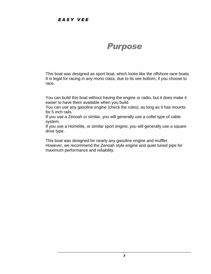
This boat was designed as sport boat, which looks like the offshore race boats. It is legal for racing in any mono class, due to its vee bottom, if you choose to race. You can build this boat without having the engine or radio, but it does make it easier to have them available when you build. You can use any gasoline engine (check the rules), as long as it has mounts for 5 inch rails. If you use a Zenoah or similar, you will generally use a collet type of cable system. If you use a Homelite, or similar sport engine, you will generally use a square drive type. This boat was designed for nearly any gasoline engine and muffler. However, we recommend the Zenoah style engine and quiet tuned pipe for maximum performance and reliability.
E A S Y V E E
3
Tools and supplies needed to build:
Small wood plane (mini plane)
Sanding blocks with 80 and 220 grit paper
Drill with bits
Right angle drill or attachment
Square
12x48 FLAT plywood (the thicker the better)
Medium CA glue and accelerator
Good quality 30 minute epoxy
Epoxy finishing resin
2 feet of 6 ounce fiberglass cloth, 3 inches wide
Medium sized rubber bands (3 or 4)
3 inch screws or nails
Waxed paper
Lots of clamps! Spring clamps, paper clamps, c clamps, etc.
Razor saw
Wide tape
Wood filler
Primer
Paint
E A S Y V E E
4
Additional items needed to complete:
Gasoline engine with 5 inch mounts (Zipp 3409 Zenoah mounts)
.250 Collet for engine (Zenoah type engines) (Zipp 3446 )
.250 24 inch cable w/welded stub shaft (Zenoah type engines) (Zipp 3444 )
.250-.250 brass ferrule (sport “trimmer” type engine) (Zipp 3433 )
24 inch section of square drive cable (“trimmer” type engine- get from trimmer)
¼ inch stub shaft (“trimmer” type engine) (Zipp 3447 )
¼ inch thrust bearing (“trimmer” type engine) (Aeromarine # 1502 )
Tuned pipe w/90 or 100 degree header or canister muffler (Zipp 2000/2010 or 2011)
2 channel surface radio with 1 standard and 1 heavy duty servo (100 in/oz minimum)
Throttle pushrod (Zipp 3462)
Rudder pushrod (at least “4-40” size) (Zipp 3463)
2 pushrod seals (Zipp # 3404 )
14-24 ounce fuel tank (or 500-750mL IV bag) and tubing (gasoline compatible)
.250 stinger type drive (Zipp 3401)
.250 drive dog (Zipp # 3405 )
70 mm prop (starting point) (Zipp 4000)
Prop nuts (Zipp # 3450 )
Cable grease (Aeromarine # 7145 )
Large rudder (water pickup type- Zipp #3402 or 3413)
3 feet large silicone tubing (water line, Zipp 3461)
Trim tabs and turn fin (Zipp 3417 and 3410)
36 inch length of 5/16 brass tubing (Zipp 3452)
Floatation (pool noodles, foam, etc.)
E A S Y V E E
5
Before we can start building, we need to do some prep work. Good prep work will pay off later with a straight, true running boat. First, we need a flat work surface. Nothing else will do. If you don’t have a perfectly flat bench, you can make one with your piece of 12x48 plywood. Simply screw a couple of 2x4’s lengthwise to the bottom. Make sure the 2x4’s are straight! You can then put this on a bench, and shim the corners to make it steady. Or, if you are really pressed for space, you can set it on a couple of saw horses.
The Build
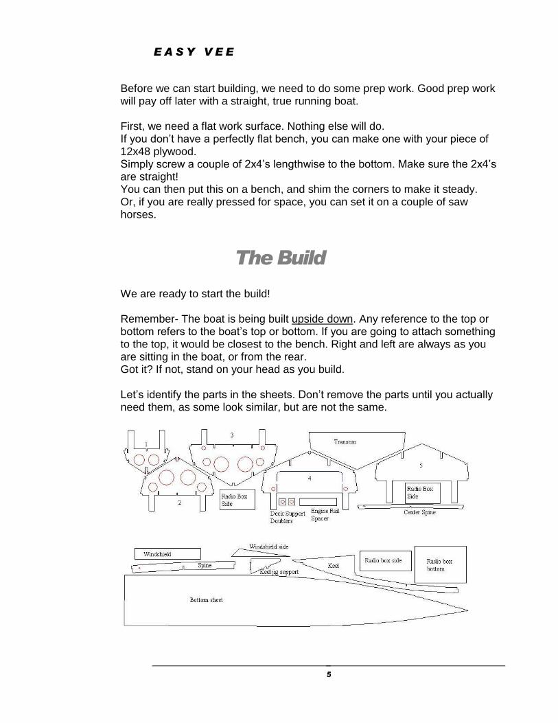
We are ready to start the build! Remember- The boat is being built upside down. Any reference to the top or bottom refers to the boat’s top or bottom. If you are going to attach something to the top, it would be closest to the bench. Right and left are always as you are sitting in the boat, or from the rear. Got it? If not, stand on your head as you build. Let’s identify the parts in the sheets. Don’t remove the parts until you actually need them, as some look similar, but are not the same.
E A S Y V E E
6
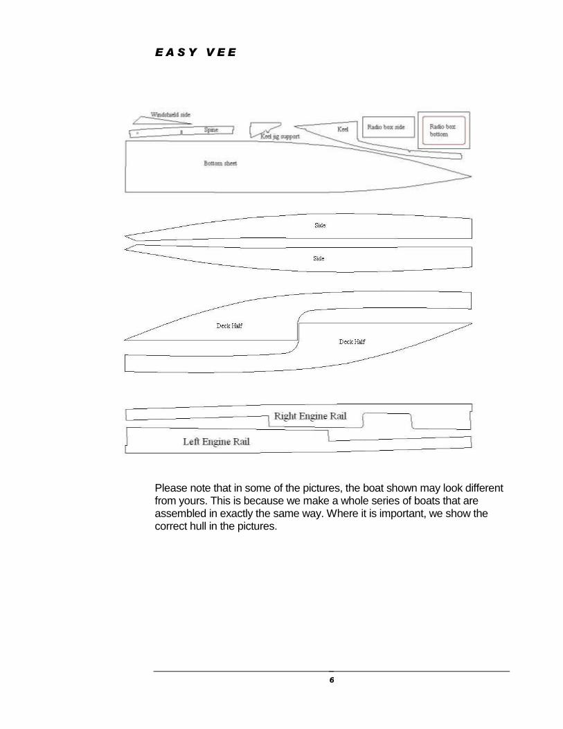
Please note that in some of the pictures, the boat shown may look different from yours. This is because we make a whole series of boats that are assembled in exactly the same way. Where it is important, we show the correct hull in the pictures.
E A S Y V E E
7
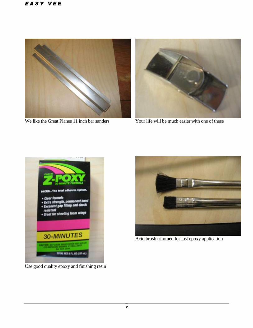
We like the Great Planes 11 inch bar sanders
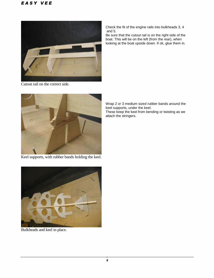
Use good quality epoxy and finishing resin
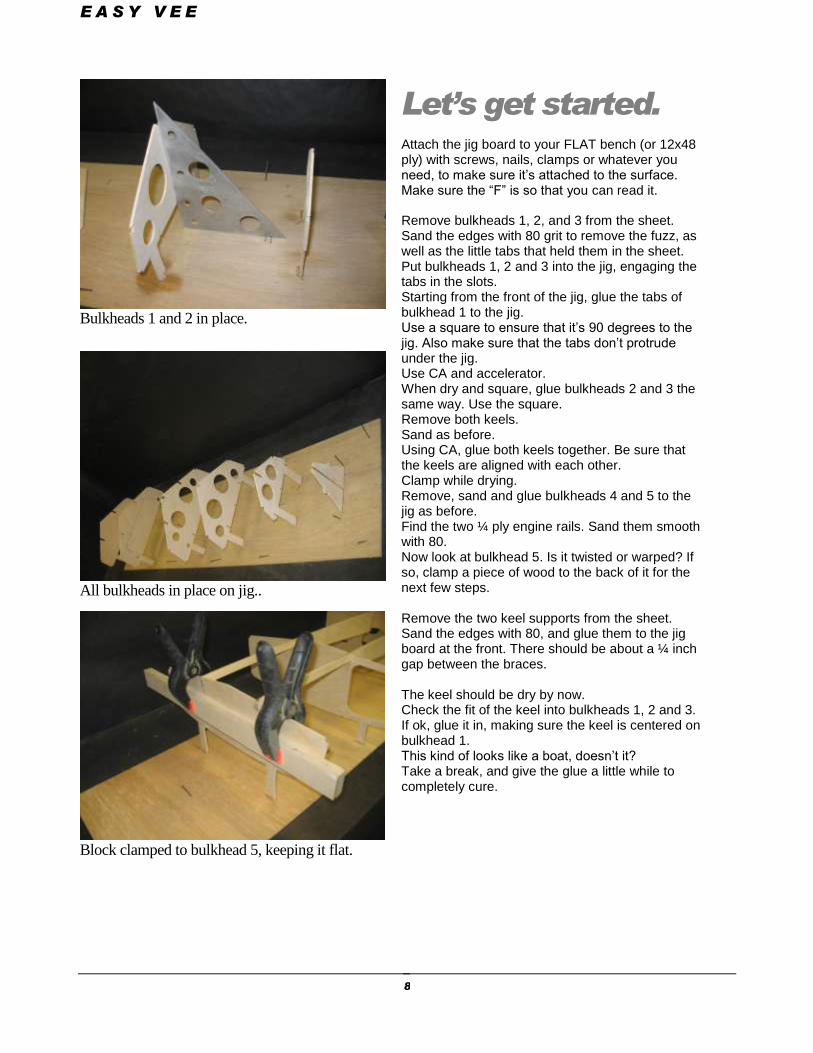
Your life will be much easier with one of these
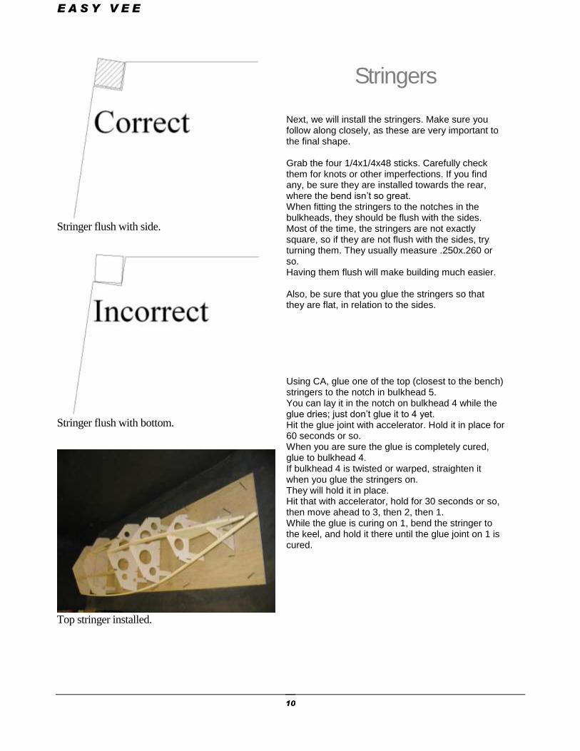
Acid brush trimmed for fast epoxy application
E A S Y V E E
8
Bulkheads 1 and 2 in place.
All bulkheads in place on jig..
Block clamped to bulkhead 5, keeping it flat.
Let’s get started.
Attach the jig board to your FLAT bench (or 12x48 ply) with screws, nails, clamps or whatever you need, to make sure it’s attached to the surface. Make sure the “F” is so that you can read it.
Remove bulkheads 1, 2, and 3 from the sheet. Sand the edges with 80 grit to remove the fuzz, as well as the little tabs that held them in the sheet. Put bulkheads 1, 2 and 3 into the jig, engaging the tabs in the slots. Starting from the front of the jig, glue the tabs of bulkhead 1 to the jig. Use a square to ensure that it’s 90 degrees to the jig. Also make sure that the tabs don’t protrude under the jig. Use CA and accelerator. When dry and square, glue bulkheads 2 and 3 the same way. Use the square. Remove both keels. Sand as before. Using CA, glue both keels together. Be sure that the keels are aligned with each other. Clamp while drying. Remove, sand and glue bulkheads 4 and 5 to the jig as before. Find the two ¼ ply engine rails. Sand them smooth with 80. Now look at bulkhead 5. Is it twisted or warped? If so, clamp a piece of wood to the back of it for the next few steps. Remove the two keel supports from the sheet. Sand the edges with 80, and glue them to the jig board at the front. There should be about a ¼ inch gap between the braces. The keel should be dry by now. Check the fit of the keel into bulkheads 1, 2 and 3. If ok, glue it in, making sure the keel is centered on bulkhead 1. This kind of looks like a boat, doesn’t it? Take a break, and give the glue a little while to completely cure.
E A S Y V E E
9
Cutout rail on the correct side.
Keel supports, with rubber bands holding the keel.
Bulkheads and keel in place.
Check the fit of the engine rails into bulkheads 3, 4 and 5. Be sure that the cutout rail is on the right side of the boat. This will be on the left (from the rear), when looking at the boat upside down. If ok, glue them in.
Wrap 2 or 3 medium sized rubber bands around the keel supports, under the keel. These keep the keel from bending or twisting as we attach the stringers.
E A S Y V E E
10
Stringer flush with side.
Stringer flush with bottom.
Top stringer installed.
Stringers
Next, we will install the stringers. Make sure you follow along closely, as these are very important to the final shape. Grab the four 1/4x1/4x48 sticks. Carefully check them for knots or other imperfections. If you find any, be sure they are installed towards the rear, where the bend isn’t so great. When fitting the stringers to the notches in the bulkheads, they should be flush with the sides. Most of the time, the stringers are not exactly square, so if they are not flush with the sides, try turning them. They usually measure .250x.260 or so. Having them flush will make building much easier. Also, be sure that you glue the stringers so that they are flat, in relation to the sides. Using CA, glue one of the top (closest to the bench) stringers to the notch in bulkhead 5. You can lay it in the notch on bulkhead 4 while the glue dries; just don’t glue it to 4 yet. Hit the glue joint with accelerator. Hold it in place for 60 seconds or so. When you are sure the glue is completely cured, glue to bulkhead 4. If bulkhead 4 is twisted or warped, straighten it when you glue the stringers on. They will hold it in place. Hit that with accelerator, hold for 30 seconds or so, then move ahead to 3, then 2, then 1. While the glue is curing on 1, bend the stringer to the keel, and hold it there until the glue joint on 1 is cured.
E A S Y V E E
11
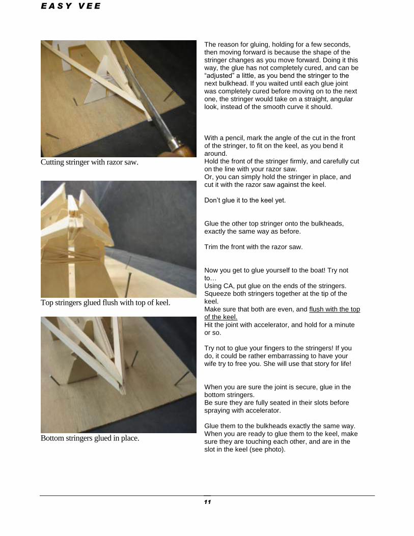
Cutting stringer with razor saw.
Top stringers glued flush with top of keel.
Bottom stringers glued in place.
The reason for gluing, holding for a few seconds, then moving forward is because the shape of the stringer changes as you move forward. Doing it this way, the glue has not completely cured, and can be “adjusted” a little, as you bend the stringer to the next bulkhead. If you waited until each glue joint was completely cured before moving on to the next one, the stringer would take on a straight, angular look, instead of the smooth curve it should. With a pencil, mark the angle of the cut in the front of the stringer, to fit on the keel, as you bend it around. Hold the front of the stringer firmly, and carefully cut on the line with your razor saw. Or, you can simply hold the stringer in place, and cut it with the razor saw against the keel. Don’t glue it to the keel yet. Glue the other top stringer onto the bulkheads, exactly the same way as before. Trim the front with the razor saw. Now you get to glue yourself to the boat! Try not to… Using CA, put glue on the ends of the stringers. Squeeze both stringers together at the tip of the keel. Make sure that both are even, and flush with the top of the keel. Hit the joint with accelerator, and hold for a minute or so. Try not to glue your fingers to the stringers! If you do, it could be rather embarrassing to have your wife try to free you. She will use that story for life! When you are sure the joint is secure, glue in the bottom stringers. Be sure they are fully seated in their slots before spraying with accelerator. Glue them to the bulkheads exactly the same way. When you are ready to glue them to the keel, make sure they are touching each other, and are in the slot in the keel (see photo).
E A S Y V E E
12
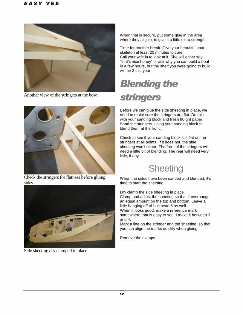
Another view of the stringers at the bow.
Check the stringers for flatness before gluing
sides.
Side sheeting dry clamped in place.
When that is secure, put some glue in the area where they all join, to give it a little extra strength.
Time for another break. Give your beautiful boat skeleton at least 20 minutes to cure. Call your wife in to look at it. She will either say “that’s nice honey” or ask why you can build a boat in a few hours, but the shelf you were going to build will be 3 this year.
Blending the
stringers Before we can glue the side sheeting in place, we need to make sure the stringers are flat. Do this with your sanding block and fresh 80 grit paper. Sand the stringers, using your sanding block to blend them at the front. Check to see if your sanding block sits flat on the stringers at all points. If it does not, the side sheeting won’t either. The front of the stringers will need a little bit of blending. The rear will need very little, if any.
Sheeting When the sides have been sanded and blended, it’s time to start the sheeting. Dry clamp the side sheeting in place. Clamp and adjust the sheeting so that it overhangs an equal amount on the top and bottom. Leave a little hanging off of bulkhead 5 as well. When it looks good, make a reference mark somewhere that is easy to see. I make it between 3 and 4. Mark a line on the stringer and the sheeting, so that you can align the marks quickly when gluing. Remove the clamps.
E A S Y V E E
13
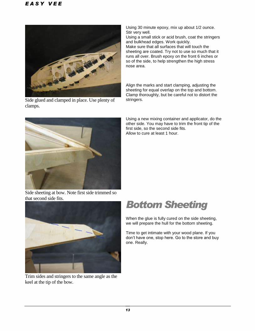
Side glued and clamped in place. Use plenty of
clamps.
Side sheeting at bow. Note first side trimmed so
that second side fits.
Trim sides and stringers to the same angle as the
keel at the tip of the bow.
Using 30 minute epoxy, mix up about 1/2 ounce. Stir very well. Using a small stick or acid brush, coat the stringers and bulkhead edges. Work quickly. Make sure that all surfaces that will touch the sheeting are coated. Try not to use so much that it runs all over. Brush epoxy on the front 6 inches or so of the side, to help strengthen the high stress nose area. Align the marks and start clamping, adjusting the sheeting for equal overlap on the top and bottom. Clamp thoroughly, but be careful not to distort the stringers. Using a new mixing container and applicator, do the other side. You may have to trim the front tip of the first side, so the second side fits. Allow to cure at least 1 hour.
Bottom Sheeting When the glue is fully cured on the side sheeting, we will prepare the hull for the bottom sheeting. Time to get intimate with your wood plane. If you don’t have one, stop here. Go to the store and buy one. Really.
E A S Y V E E
14
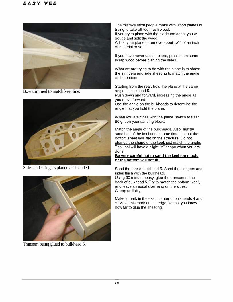
Bow trimmed to match keel line.
Sides and stringers planed and sanded.
Transom being glued to bulkhead 5.
The mistake most people make with wood planes is trying to take off too much wood. If you try to plane with the blade too deep, you will gouge and split the wood. Adjust your plane to remove about 1/64 of an inch of material or so. If you have never used a plane, practice on some scrap wood before planing the sides. What we are trying to do with the plane is to shave the stringers and side sheeting to match the angle of the bottom. Starting from the rear, hold the plane at the same angle as bulkhead 5. Push down and forward, increasing the angle as you move forward. Use the angle on the bulkheads to determine the angle that you hold the plane. When you are close with the plane, switch to fresh 80 grit on your sanding block.
Match the angle of the bulkheads. Also, lightly sand half of the keel at the same time, so that the bottom sheet lays flat on the structure. Do not change the shape of the keel, just match the angle. The keel will have a slight “V” shape when you are done. Be very careful not to sand the keel too much, or the bottom will not fit! Sand the rear of bulkhead 5. Sand the stringers and sides flush with the bulkhead. Using 30 minute epoxy, glue the transom to the back of bulkhead 5. Try to match the bottom “vee”, and leave an equal overhang on the sides. Clamp until dry.
Make a mark in the exact center of bulkheads 4 and 5. Make this mark on the edge, so that you know how far to glue the sheeting.
E A S Y V E E
15
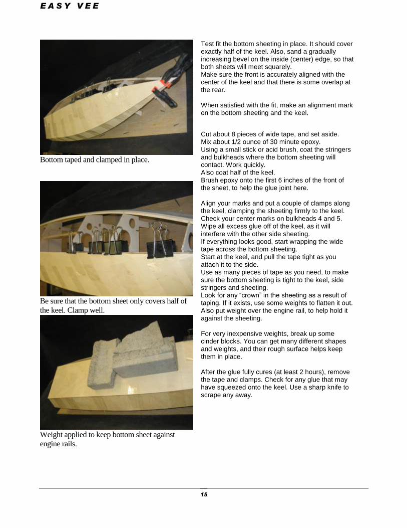
Bottom taped and clamped in place.
Be sure that the bottom sheet only covers half of
the keel. Clamp well.
Weight applied to keep bottom sheet against
engine rails.
Test fit the bottom sheeting in place. It should cover exactly half of the keel. Also, sand a gradually increasing bevel on the inside (center) edge, so that both sheets will meet squarely. Make sure the front is accurately aligned with the center of the keel and that there is some overlap at the rear. When satisfied with the fit, make an alignment mark on the bottom sheeting and the keel.
Cut about 8 pieces of wide tape, and set aside. Mix about 1/2 ounce of 30 minute epoxy. Using a small stick or acid brush, coat the stringers and bulkheads where the bottom sheeting will contact. Work quickly. Also coat half of the keel. Brush epoxy onto the first 6 inches of the front of the sheet, to help the glue joint here. Align your marks and put a couple of clamps along the keel, clamping the sheeting firmly to the keel. Check your center marks on bulkheads 4 and 5. Wipe all excess glue off of the keel, as it will interfere with the other side sheeting. If everything looks good, start wrapping the wide tape across the bottom sheeting. Start at the keel, and pull the tape tight as you attach it to the side. Use as many pieces of tape as you need, to make sure the bottom sheeting is tight to the keel, side stringers and sheeting. Look for any “crown” in the sheeting as a result of taping. If it exists, use some weights to flatten it out. Also put weight over the engine rail, to help hold it against the sheeting. For very inexpensive weights, break up some cinder blocks. You can get many different shapes and weights, and their rough surface helps keep them in place. After the glue fully cures (at least 2 hours), remove the tape and clamps. Check for any glue that may have squeezed onto the keel. Use a sharp knife to scrape any away.
E A S Y V E E
16
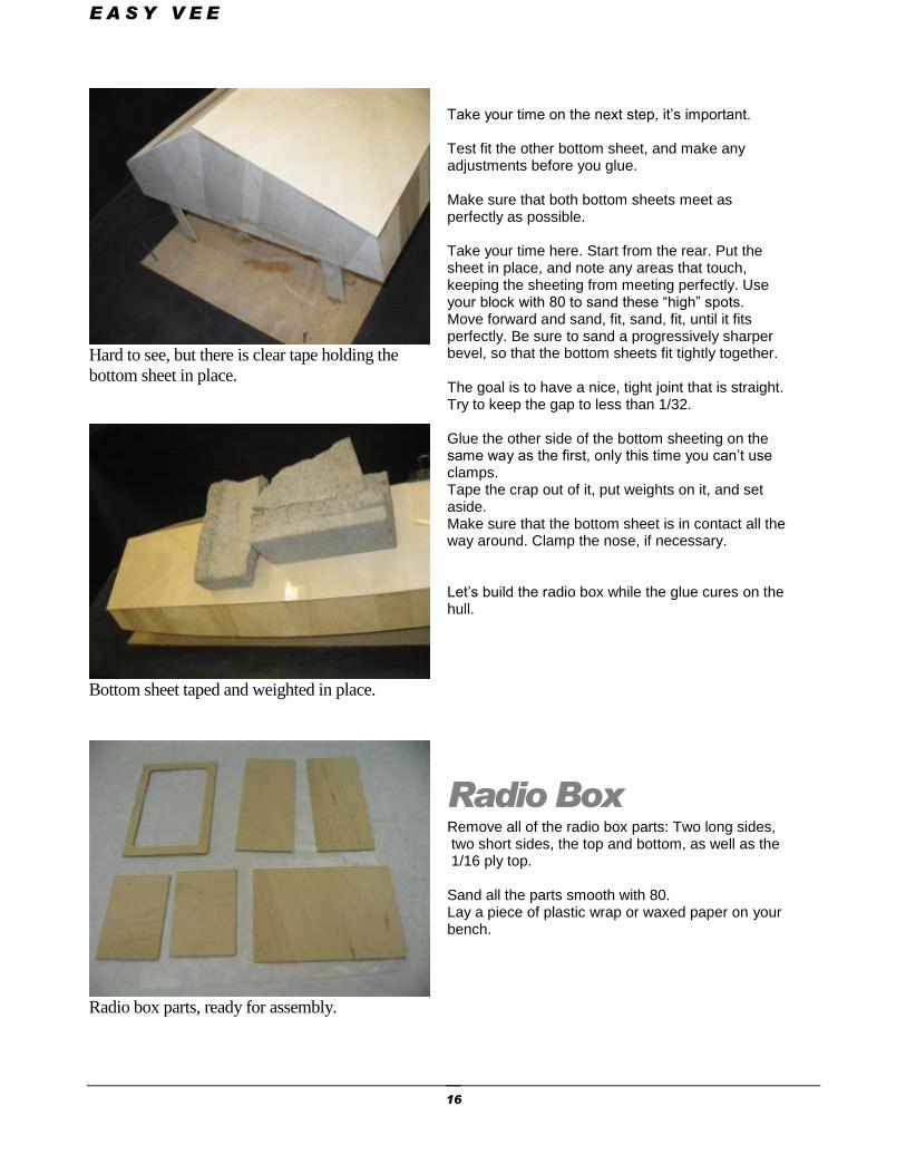
Hard to see, but there is clear tape holding the
bottom sheet in place.
Bottom sheet taped and weighted in place.
Radio box parts, ready for assembly.
Take your time on the next step, it’s important. Test fit the other bottom sheet, and make any adjustments before you glue. Make sure that both bottom sheets meet as perfectly as possible. Take your time here. Start from the rear. Put the sheet in place, and note any areas that touch, keeping the sheeting from meeting perfectly. Use your block with 80 to sand these “high” spots. Move forward and sand, fit, sand, fit, until it fits perfectly. Be sure to sand a progressively sharper bevel, so that the bottom sheets fit tightly together. The goal is to have a nice, tight joint that is straight. Try to keep the gap to less than 1/32. Glue the other side of the bottom sheeting on the same way as the first, only this time you can’t use clamps. Tape the crap out of it, put weights on it, and set aside. Make sure that the bottom sheet is in contact all the way around. Clamp the nose, if necessary. Let’s build the radio box while the glue cures on the hull.
Radio Box Remove all of the radio box parts: Two long sides, two short sides, the top and bottom, as well as the 1/16 ply top. Sand all the parts smooth with 80. Lay a piece of plastic wrap or waxed paper on your bench.
E A S Y V E E
17
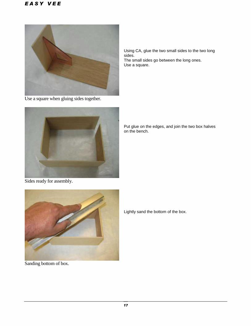
Use a square when gluing sides together.
Sides ready for assembly.
Sanding bottom of box.
Using CA, glue the two small sides to the two long sides. The small sides go between the long ones. Use a square. Put glue on the edges, and join the two box halves on the bench. Lightly sand the bottom of the box.
E A S Y V E E
18
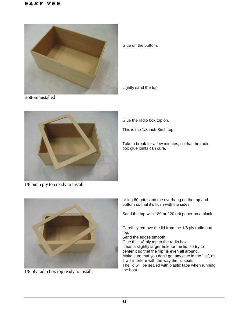
Bottom installed
1/8 birch ply top ready to install.
1/8 ply radio box top ready to install.
Glue on the bottom. Lightly sand the top. Glue the radio box top on. This is the 1/8 inch Birch top. Take a break for a few minutes, so that the radio box glue joints can cure. Using 80 grit, sand the overhang on the top and bottom so that it’s flush with the sides. Sand the top with 180 or 220 grit paper on a block. Carefully remove the lid from the 1/8 ply radio box top. Sand the edges smooth. Glue the 1/8 ply top to the radio box. It has a slightly larger hole for the lid, so try to center it so that the “lip” is even all around. Make sure that you don’t get any glue in the “lip”, as it will interfere with the way the lid seats. The lid will be sealed with plastic tape when running the boat.
E A S Y V E E
19
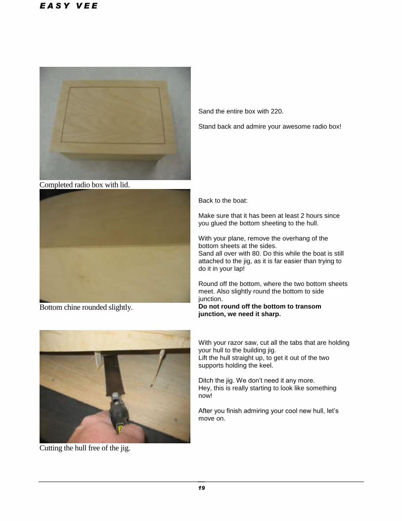
Completed radio box with lid.
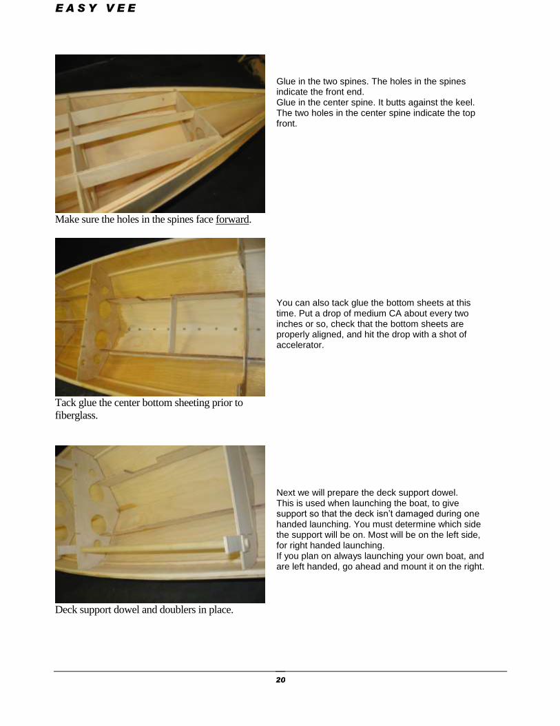
Bottom chine rounded slightly.
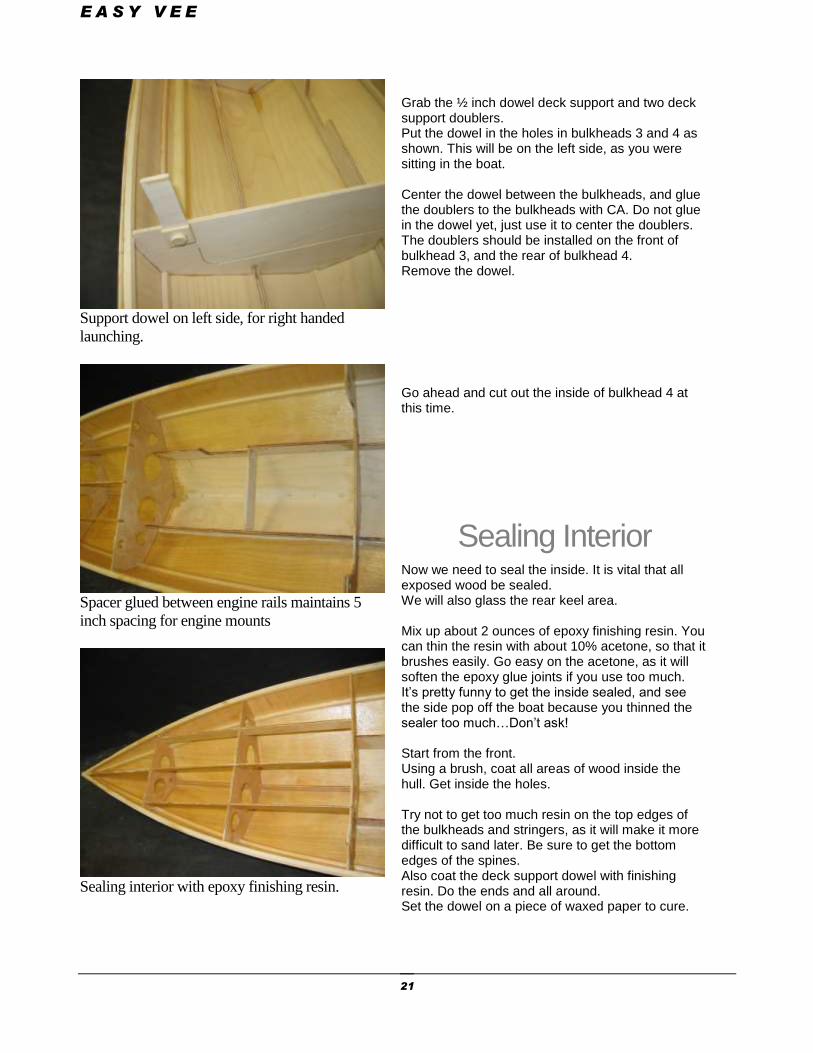
Cutting the hull free of the jig.
Sand the entire box with 220. Stand back and admire your awesome radio box!
Back to the boat: Make sure that it has been at least 2 hours since you glued the bottom sheeting to the hull. With your plane, remove the overhang of the bottom sheets at the sides. Sand all over with 80. Do this while the boat is still attached to the jig, as it is far easier than trying to do it in your lap! Round off the bottom, where the two bottom sheets meet. Also slightly round the bottom to side junction. Do not round off the bottom to transom junction, we need it sharp.
With your razor saw, cut all the tabs that are holding your hull to the building jig. Lift the hull straight up, to get it out of the two supports holding the keel. Ditch the jig. We don’t need it any more. Hey, this is really starting to look like something now! After you finish admiring your cool new hull, let’s move on.
E A S Y V E E
20
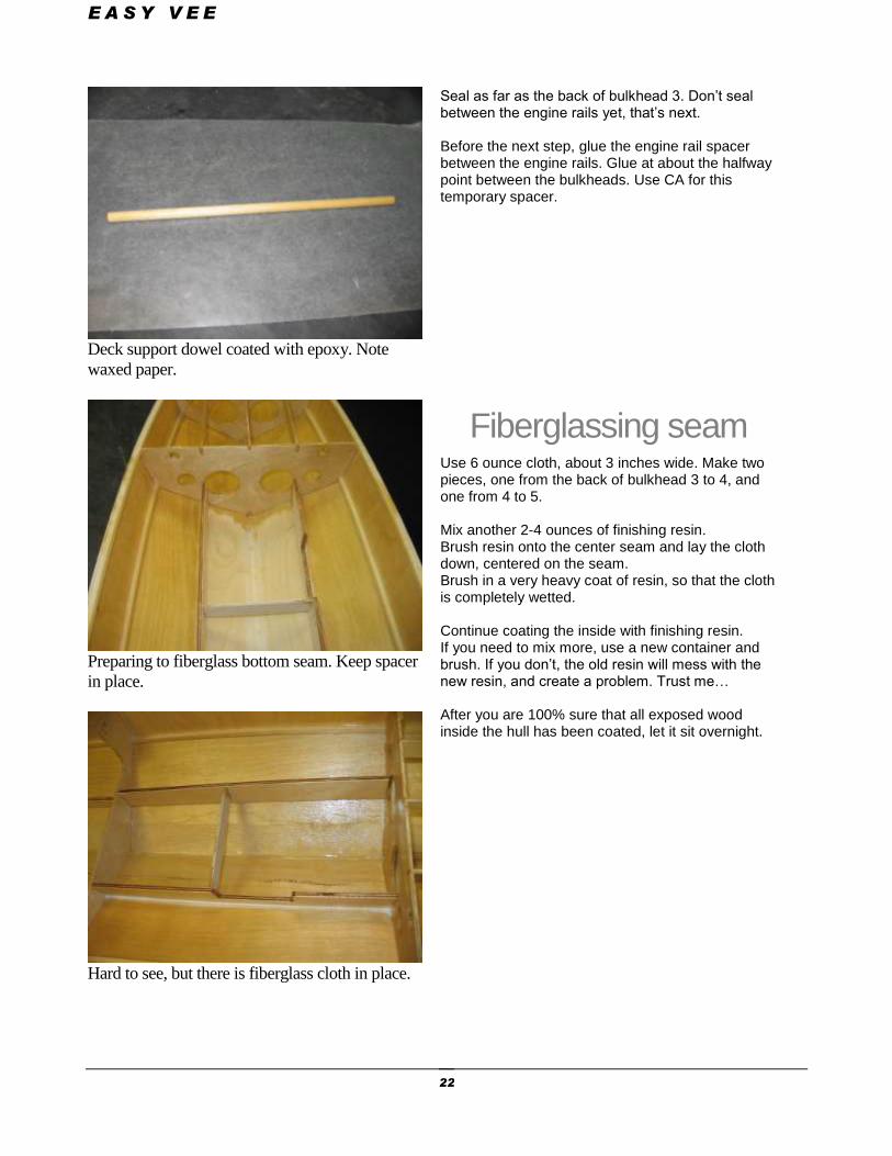
Make sure the holes in the spines face forward.
Tack glue the center bottom sheeting prior to
fiberglass.
Deck support dowel and doublers in place.
Glue in the two spines. The holes in the spines indicate the front end. Glue in the center spine. It butts against the keel. The two holes in the center spine indicate the top front. You can also tack glue the bottom sheets at this time. Put a drop of medium CA about every two inches or so, check that the bottom sheets are properly aligned, and hit the drop with a shot of accelerator. Next we will prepare the deck support dowel. This is used when launching the boat, to give support so that the deck isn’t damaged during one handed launching. You must determine which side the support will be on. Most will be on the left side, for right handed launching. If you plan on always launching your own boat, and are left handed, go ahead and mount it on the right.
E A S Y V E E
21
Support dowel on left side, for right handed
launching.
Spacer glued between engine rails maintains 5
inch spacing for engine mounts
Sealing interior with epoxy finishing resin.
Grab the ½ inch dowel deck support and two deck support doublers. Put the dowel in the holes in bulkheads 3 and 4 as shown. This will be on the left side, as you were sitting in the boat. Center the dowel between the bulkheads, and glue the doublers to the bulkheads with CA. Do not glue in the dowel yet, just use it to center the doublers. The doublers should be installed on the front of bulkhead 3, and the rear of bulkhead 4. Remove the dowel.
Go ahead and cut out the inside of bulkhead 4 at this time.
Sealing Interior Now we need to seal the inside. It is vital that all exposed wood be sealed. We will also glass the rear keel area. Mix up about 2 ounces of epoxy finishing resin. You can thin the resin with about 10% acetone, so that it brushes easily. Go easy on the acetone, as it will soften the epoxy glue joints if you use too much. It’s pretty funny to get the inside sealed, and see the side pop off the boat because you thinned the sealer too much…Don’t ask! Start from the front. Using a brush, coat all areas of wood inside the hull. Get inside the holes. Try not to get too much resin on the top edges of the bulkheads and stringers, as it will make it more difficult to sand later. Be sure to get the bottom edges of the spines. Also coat the deck support dowel with finishing resin. Do the ends and all around. Set the dowel on a piece of waxed paper to cure.
E A S Y V E E
22
Deck support dowel coated with epoxy. Note
waxed paper.
Preparing to fiberglass bottom seam. Keep spacer
in place.
Hard to see, but there is fiberglass cloth in place.
Seal as far as the back of bulkhead 3. Don’t seal between the engine rails yet, that’s next. Before the next step, glue the engine rail spacer between the engine rails. Glue at about the halfway point between the bulkheads. Use CA for this temporary spacer.
Fiberglassing seam Use 6 ounce cloth, about 3 inches wide. Make two pieces, one from the back of bulkhead 3 to 4, and one from 4 to 5. Mix another 2-4 ounces of finishing resin. Brush resin onto the center seam and lay the cloth down, centered on the seam. Brush in a very heavy coat of resin, so that the cloth is completely wetted. Continue coating the inside with finishing resin. If you need to mix more, use a new container and brush. If you don’t, the old resin will mess with the new resin, and create a problem. Trust me… After you are 100% sure that all exposed wood inside the hull has been coated, let it sit overnight.
E A S Y V E E
23
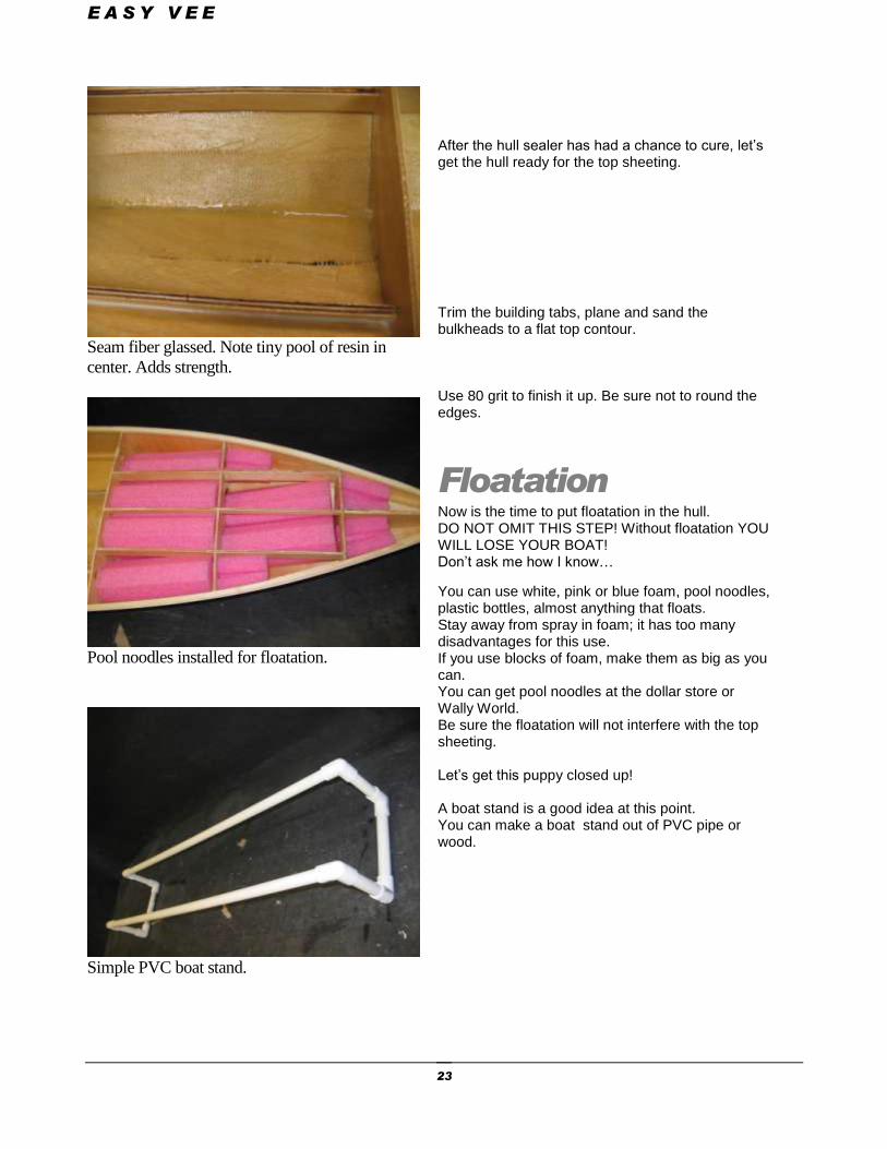
Seam fiber glassed. Note tiny pool of resin in
center. Adds strength.
Pool noodles installed for floatation.
Simple PVC boat stand.
After the hull sealer has had a chance to cure, let’s get the hull ready for the top sheeting. Trim the building tabs, plane and sand the bulkheads to a flat top contour. Use 80 grit to finish it up. Be sure not to round the edges.
Floatation Now is the time to put floatation in the hull. DO NOT OMIT THIS STEP! Without floatation YOU WILL LOSE YOUR BOAT! Don’t ask me how I know…
You can use white, pink or blue foam, pool noodles, plastic bottles, almost anything that floats. Stay away from spray in foam; it has too many disadvantages for this use. If you use blocks of foam, make them as big as you can. You can get pool noodles at the dollar store or Wally World. Be sure the floatation will not interfere with the top sheeting. Let’s get this puppy closed up! A boat stand is a good idea at this point. You can make a boat stand out of PVC pipe or wood.
E A S Y V E E
24
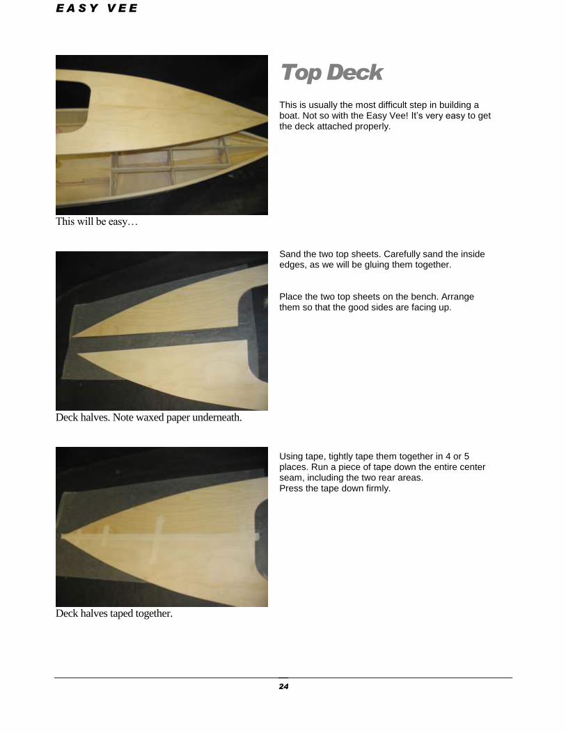
This will be easy…
Deck halves. Note waxed paper underneath.
Deck halves taped together.
Top Deck This is usually the most difficult step in building a boat. Not so with the Easy Vee! It’s very easy to get the deck attached properly. Sand the two top sheets. Carefully sand the inside edges, as we will be gluing them together. Place the two top sheets on the bench. Arrange them so that the good sides are facing up. Using tape, tightly tape them together in 4 or 5 places. Run a piece of tape down the entire center seam, including the two rear areas. Press the tape down firmly.
E A S Y V E E
25
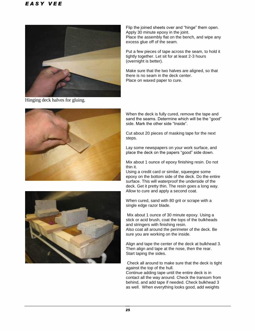
Hinging deck halves for gluing.
Flip the joined sheets over and “hinge” them open. Apply 30 minute epoxy in the joint. Place the assembly flat on the bench, and wipe any excess glue off of the seam. Put a few pieces of tape across the seam, to hold it tightly together. Let sit for at least 2-3 hours (overnight is better). Make sure that the two halves are aligned, so that there is no seam in the deck center. Place on waxed paper to cure. When the deck is fully cured, remove the tape and sand the seams. Determine which will be the “good” side. Mark the other side “Inside”. Cut about 20 pieces of masking tape for the next steps. Lay some newspapers on your work surface, and place the deck on the papers “good” side down. Mix about 1 ounce of epoxy finishing resin. Do not thin it. Using a credit card or similar, squeegee some epoxy on the bottom side of the deck. Do the entire surface. This will waterproof the underside of the deck. Get it pretty thin. The resin goes a long way. Allow to cure and apply a second coat. When cured, sand with 80 grit or scrape with a single edge razor blade. Mix about 1 ounce of 30 minute epoxy. Using a stick or acid brush, coat the tops of the bulkheads and stringers with finishing resin. Also coat all around the perimeter of the deck. Be sure you are working on the inside. Align and tape the center of the deck at bulkhead 3. Then align and tape at the nose, then the rear. Start taping the sides. Check all around to make sure that the deck is tight against the top of the hull. Continue adding tape until the entire deck is in contact all the way around. Check the transom from behind, and add tape if needed. Check bulkhead 3 as well. When everything looks good, add weights
E A S Y V E E
26
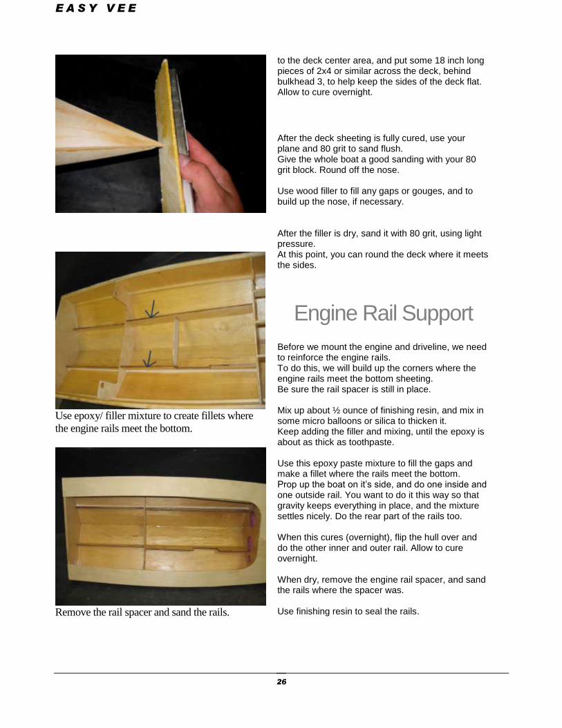
Use epoxy/ filler mixture to create fillets where
the engine rails meet the bottom.
Remove the rail spacer and sand the rails.
to the deck center area, and put some 18 inch long pieces of 2x4 or similar across the deck, behind bulkhead 3, to help keep the sides of the deck flat. Allow to cure overnight.
After the deck sheeting is fully cured, use your plane and 80 grit to sand flush. Give the whole boat a good sanding with your 80 grit block. Round off the nose. Use wood filler to fill any gaps or gouges, and to build up the nose, if necessary. After the filler is dry, sand it with 80 grit, using light pressure. At this point, you can round the deck where it meets the sides.
Engine Rail Support Before we mount the engine and driveline, we need to reinforce the engine rails. To do this, we will build up the corners where the engine rails meet the bottom sheeting. Be sure the rail spacer is still in place. Mix up about ½ ounce of finishing resin, and mix in some micro balloons or silica to thicken it. Keep adding the filler and mixing, until the epoxy is about as thick as toothpaste. Use this epoxy paste mixture to fill the gaps and make a fillet where the rails meet the bottom. Prop up the boat on it’s side, and do one inside and one outside rail. You want to do it this way so that gravity keeps everything in place, and the mixture settles nicely. Do the rear part of the rails too. When this cures (overnight), flip the hull over and do the other inner and outer rail. Allow to cure overnight. When dry, remove the engine rail spacer, and sand the rails where the spacer was. Use finishing resin to seal the rails.
E A S Y V E E
27
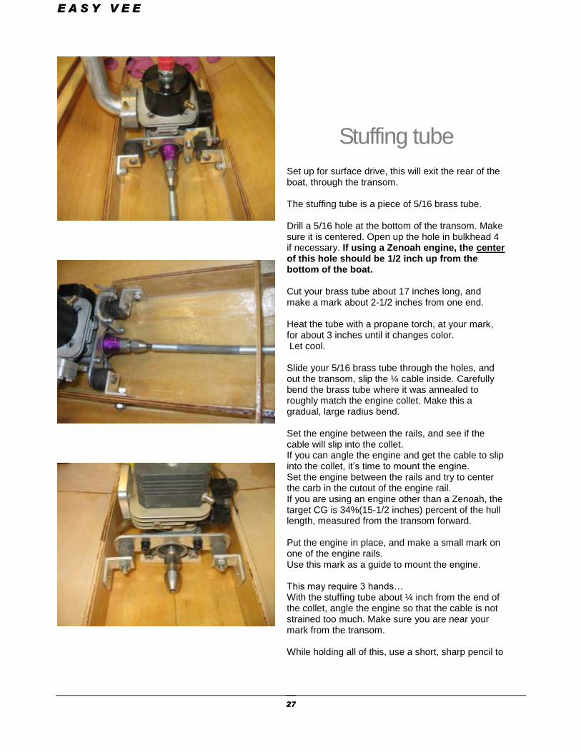
Stuffing tube Set up for surface drive, this will exit the rear of the boat, through the transom. The stuffing tube is a piece of 5/16 brass tube. Drill a 5/16 hole at the bottom of the transom. Make sure it is centered. Open up the hole in bulkhead 4 if necessary. If using a Zenoah engine, the center of this hole should be 1/2 inch up from the bottom of the boat. Cut your brass tube about 17 inches long, and make a mark about 2-1/2 inches from one end. Heat the tube with a propane torch, at your mark, for about 3 inches until it changes color. Let cool. Slide your 5/16 brass tube through the holes, and out the transom, slip the ¼ cable inside. Carefully bend the brass tube where it was annealed to roughly match the engine collet. Make this a gradual, large radius bend. Set the engine between the rails, and see if the cable will slip into the collet. If you can angle the engine and get the cable to slip into the collet, it’s time to mount the engine. Set the engine between the rails and try to center the carb in the cutout of the engine rail. If you are using an engine other than a Zenoah, the target CG is 34%(15-1/2 inches) percent of the hull length, measured from the transom forward. Put the engine in place, and make a small mark on one of the engine rails. Use this mark as a guide to mount the engine. This may require 3 hands… With the stuffing tube about ¼ inch from the end of the collet, angle the engine so that the cable is not strained too much. Make sure you are near your mark from the transom. While holding all of this, use a short, sharp pencil to
E A S Y V E E
28
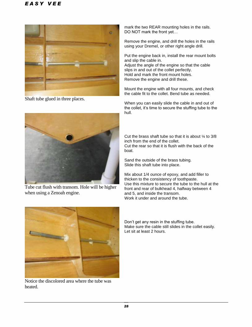
Shaft tube glued in three places.
Tube cut flush with transom. Hole will be higher
when using a Zenoah engine.
Notice the discolored area where the tube was
heated.
mark the two REAR mounting holes in the rails. DO NOT mark the front yet… Remove the engine, and drill the holes in the rails using your Dremel, or other right angle drill. Put the engine back in, install the rear mount bolts and slip the cable in. Adjust the angle of the engine so that the cable slips in and out of the collet perfectly. Hold and mark the front mount holes. Remove the engine and drill these. Mount the engine with all four mounts, and check the cable fit to the collet. Bend tube as needed. When you can easily slide the cable in and out of the collet, it’s time to secure the stuffing tube to the hull. Cut the brass shaft tube so that it is about ¼ to 3/8 inch from the end of the collet. Cut the rear so that it is flush with the back of the boat. Sand the outside of the brass tubing. Slide this shaft tube into place. Mix about 1/4 ounce of epoxy, and add filler to thicken to the consistency of toothpaste. Use this mixture to secure the tube to the hull at the front and rear of bulkhead 4, halfway between 4 and 5, and inside the transom. Work it under and around the tube. Don’t get any resin in the stuffing tube. Make sure the cable still slides in the collet easily. Let sit at least 2 hours.
E A S Y V E E
29
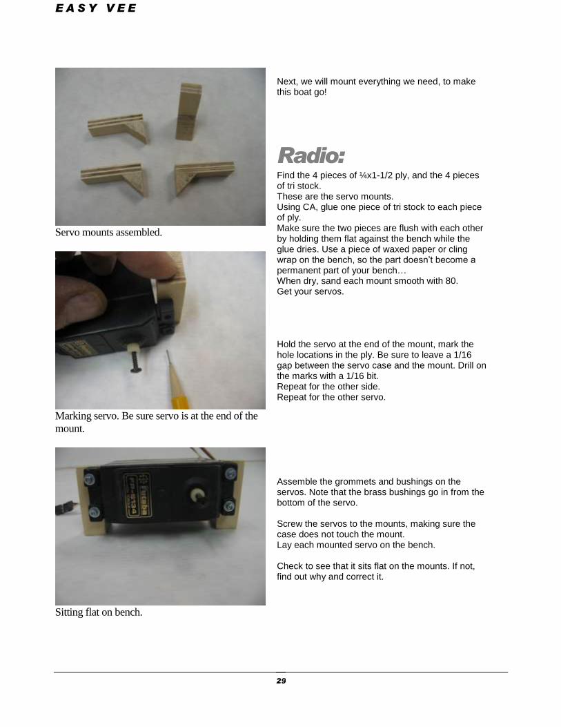
Servo mounts assembled.
Marking servo. Be sure servo is at the end of the
mount.
Sitting flat on bench.
Next, we will mount everything we need, to make this boat go!
Radio: Find the 4 pieces of ¼x1-1/2 ply, and the 4 pieces of tri stock. These are the servo mounts. Using CA, glue one piece of tri stock to each piece of ply. Make sure the two pieces are flush with each other by holding them flat against the bench while the glue dries. Use a piece of waxed paper or cling wrap on the bench, so the part doesn’t become a permanent part of your bench… When dry, sand each mount smooth with 80. Get your servos. Hold the servo at the end of the mount, mark the hole locations in the ply. Be sure to leave a 1/16 gap between the servo case and the mount. Drill on the marks with a 1/16 bit. Repeat for the other side. Repeat for the other servo. Assemble the grommets and bushings on the servos. Note that the brass bushings go in from the bottom of the servo. Screw the servos to the mounts, making sure the case does not touch the mount. Lay each mounted servo on the bench. Check to see that it sits flat on the mounts. If not, find out why and correct it.
E A S Y V E E
30
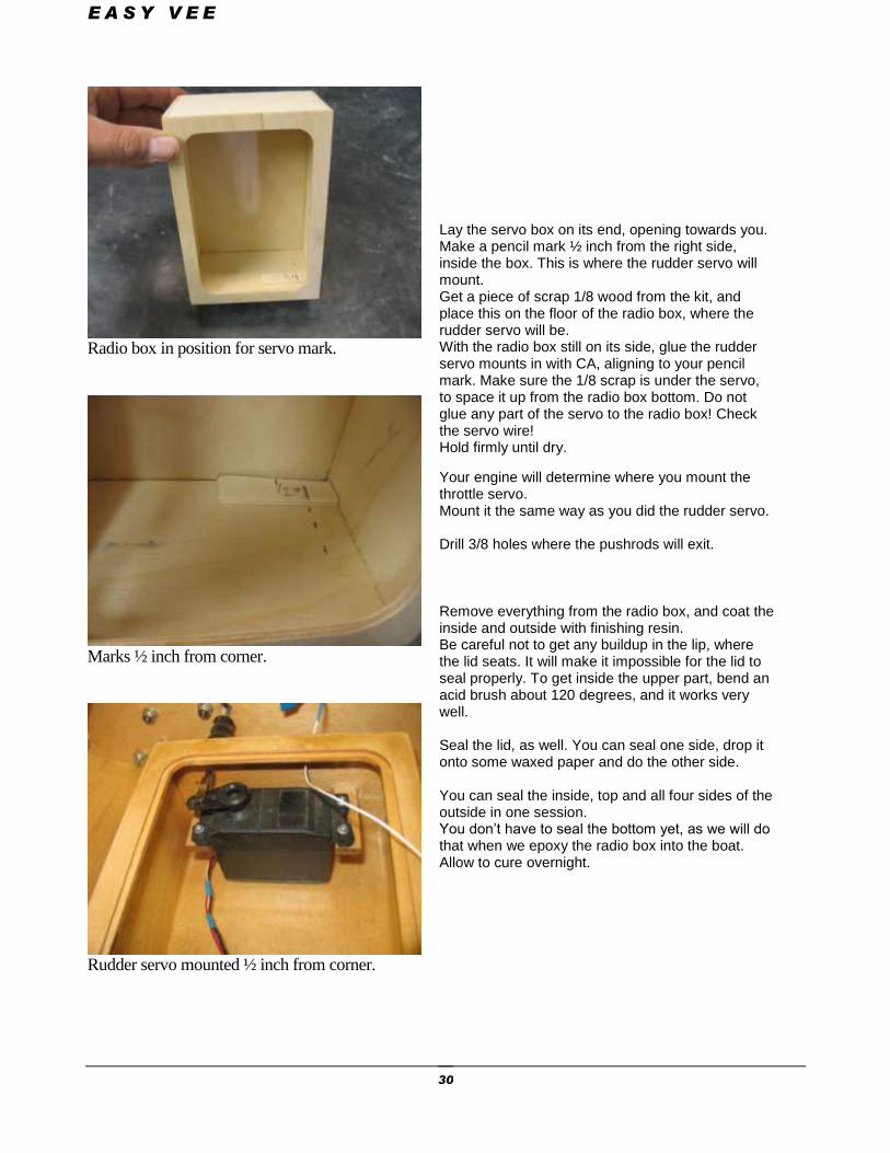
Radio box in position for servo mark.
Marks ½ inch from corner.
Rudder servo mounted ½ inch from corner.
Lay the servo box on its end, opening towards you. Make a pencil mark ½ inch from the right side, inside the box. This is where the rudder servo will mount. Get a piece of scrap 1/8 wood from the kit, and place this on the floor of the radio box, where the rudder servo will be. With the radio box still on its side, glue the rudder servo mounts in with CA, aligning to your pencil mark. Make sure the 1/8 scrap is under the servo, to space it up from the radio box bottom. Do not glue any part of the servo to the radio box! Check the servo wire! Hold firmly until dry.
Your engine will determine where you mount the throttle servo. Mount it the same way as you did the rudder servo. Drill 3/8 holes where the pushrods will exit. Remove everything from the radio box, and coat the inside and outside with finishing resin. Be careful not to get any buildup in the lip, where the lid seats. It will make it impossible for the lid to seal properly. To get inside the upper part, bend an acid brush about 120 degrees, and it works very well. Seal the lid, as well. You can seal one side, drop it onto some waxed paper and do the other side. You can seal the inside, top and all four sides of the outside in one session. You don’t have to seal the bottom yet, as we will do that when we epoxy the radio box into the boat. Allow to cure overnight.
E A S Y V E E
31
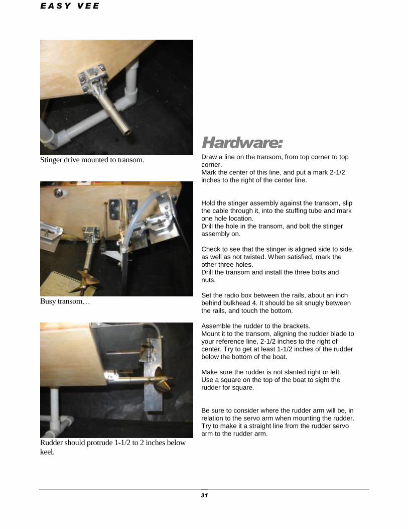
Stinger drive mounted to transom.
Busy transom…
Rudder should protrude 1-1/2 to 2 inches below
keel.
Hardware: Draw a line on the transom, from top corner to top corner. Mark the center of this line, and put a mark 2-1/2 inches to the right of the center line. Hold the stinger assembly against the transom, slip the cable through it, into the stuffing tube and mark one hole location. Drill the hole in the transom, and bolt the stinger assembly on. Check to see that the stinger is aligned side to side, as well as not twisted. When satisfied, mark the other three holes. Drill the transom and install the three bolts and nuts. Set the radio box between the rails, about an inch behind bulkhead 4. It should be sit snugly between the rails, and touch the bottom. Assemble the rudder to the brackets. Mount it to the transom, aligning the rudder blade to your reference line, 2-1/2 inches to the right of center. Try to get at least 1-1/2 inches of the rudder below the bottom of the boat. Make sure the rudder is not slanted right or left. Use a square on the top of the boat to sight the rudder for square. Be sure to consider where the rudder arm will be, in relation to the servo arm when mounting the rudder. Try to make it a straight line from the rudder servo arm to the rudder arm.
E A S Y V E E
32
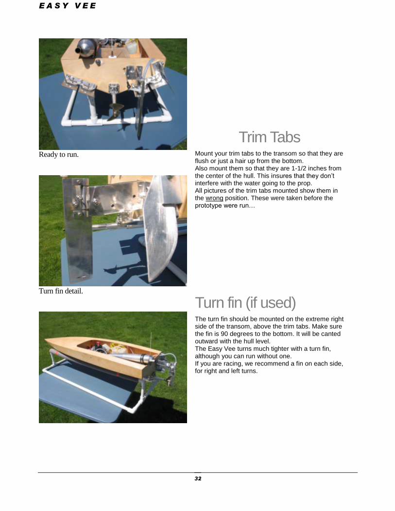
Ready to run.
Turn fin detail.
Trim Tabs Mount your trim tabs to the transom so that they are flush or just a hair up from the bottom. Also mount them so that they are 1-1/2 inches from the center of the hull. This insures that they don’t interfere with the water going to the prop. All pictures of the trim tabs mounted show them in the wrong position. These were taken before the prototype were run…
Turn fin (if used) The turn fin should be mounted on the extreme right side of the transom, above the trim tabs. Make sure the fin is 90 degrees to the bottom. It will be canted outward with the hull level. The Easy Vee turns much tighter with a turn fin, although you can run without one. If you are racing, we recommend a fin on each side, for right and left turns.
E A S Y V E E
33
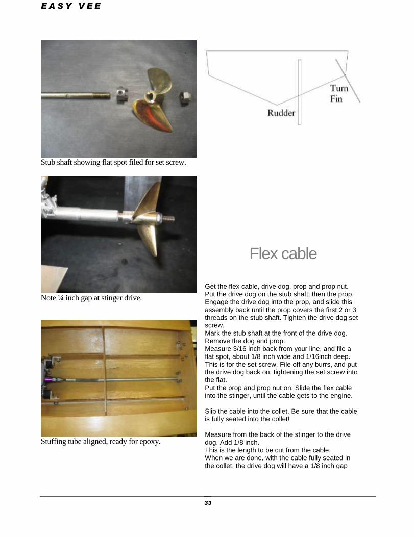
Stub shaft showing flat spot filed for set screw.
Note ¼ inch gap at stinger drive.
Stuffing tube aligned, ready for epoxy.
Flex cable Get the flex cable, drive dog, prop and prop nut. Put the drive dog on the stub shaft, then the prop. Engage the drive dog into the prop, and slide this assembly back until the prop covers the first 2 or 3 threads on the stub shaft. Tighten the drive dog set screw. Mark the stub shaft at the front of the drive dog. Remove the dog and prop. Measure 3/16 inch back from your line, and file a flat spot, about 1/8 inch wide and 1/16inch deep. This is for the set screw. File off any burrs, and put the drive dog back on, tightening the set screw into the flat. Put the prop and prop nut on. Slide the flex cable into the stinger, until the cable gets to the engine. Slip the cable into the collet. Be sure that the cable is fully seated into the collet! Measure from the back of the stinger to the drive dog. Add 1/8 inch. This is the length to be cut from the cable. When we are done, with the cable fully seated in the collet, the drive dog will have a 1/8 inch gap
E A S Y V E E
34
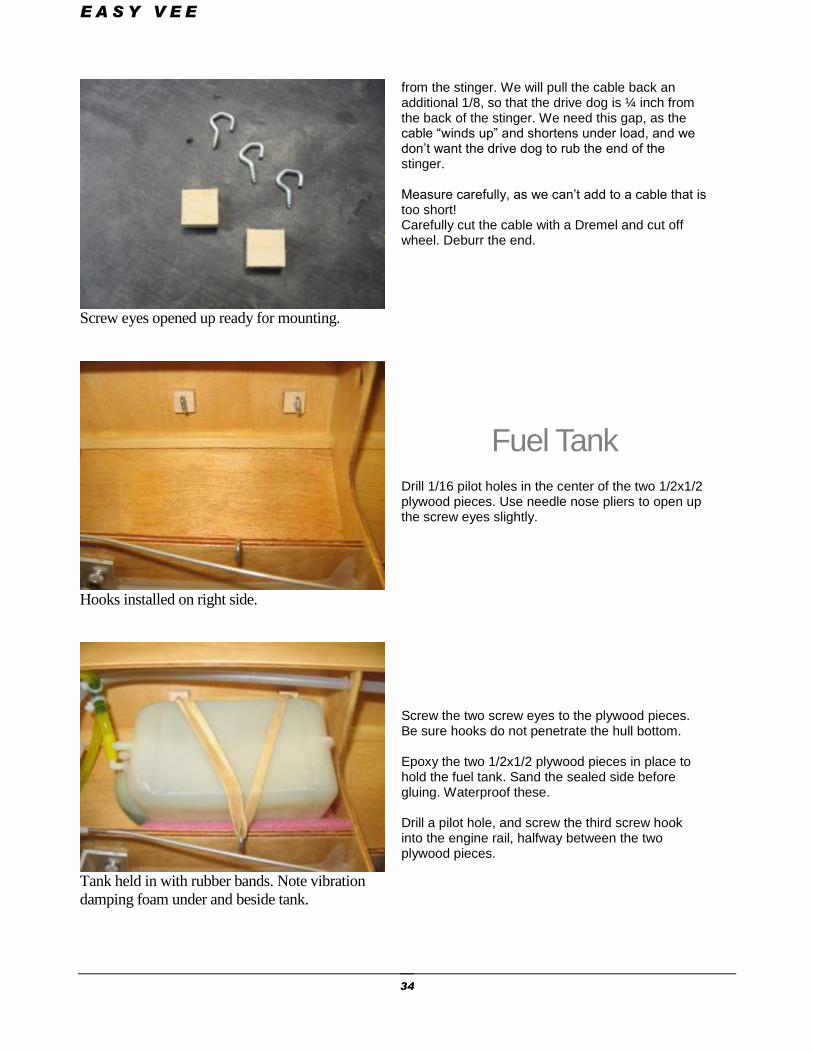
Screw eyes opened up ready for mounting.
Hooks installed on right side.
Tank held in with rubber bands. Note vibration
damping foam under and beside tank.
from the stinger. We will pull the cable back an additional 1/8, so that the drive dog is ¼ inch from the back of the stinger. We need this gap, as the cable “winds up” and shortens under load, and we don’t want the drive dog to rub the end of the stinger. Measure carefully, as we can’t add to a cable that is too short! Carefully cut the cable with a Dremel and cut off wheel. Deburr the end.
Fuel Tank
Drill 1/16 pilot holes in the center of the two 1/2x1/2 plywood pieces. Use needle nose pliers to open up the screw eyes slightly. Screw the two screw eyes to the plywood pieces. Be sure hooks do not penetrate the hull bottom. Epoxy the two 1/2x1/2 plywood pieces in place to hold the fuel tank. Sand the sealed side before gluing. Waterproof these. Drill a pilot hole, and screw the third screw hook into the engine rail, halfway between the two plywood pieces.
E A S Y V E E
35
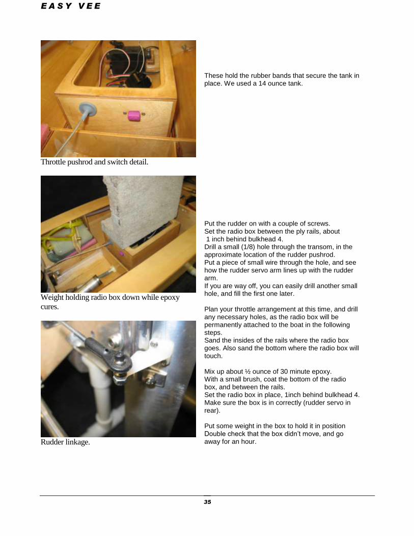
Throttle pushrod and switch detail.
Weight holding radio box down while epoxy
cures.
Rudder linkage.
These hold the rubber bands that secure the tank in place. We used a 14 ounce tank. Put the rudder on with a couple of screws. Set the radio box between the ply rails, about 1 inch behind bulkhead 4. Drill a small (1/8) hole through the transom, in the approximate location of the rudder pushrod. Put a piece of small wire through the hole, and see how the rudder servo arm lines up with the rudder arm. If you are way off, you can easily drill another small hole, and fill the first one later. Plan your throttle arrangement at this time, and drill any necessary holes, as the radio box will be permanently attached to the boat in the following steps. Sand the insides of the rails where the radio box goes. Also sand the bottom where the radio box will touch. Mix up about ½ ounce of 30 minute epoxy. With a small brush, coat the bottom of the radio box, and between the rails. Set the radio box in place, 1inch behind bulkhead 4. Make sure the box is in correctly (rudder servo in rear). Put some weight in the box to hold it in position Double check that the box didn’t move, and go away for an hour.
E A S Y V E E
36
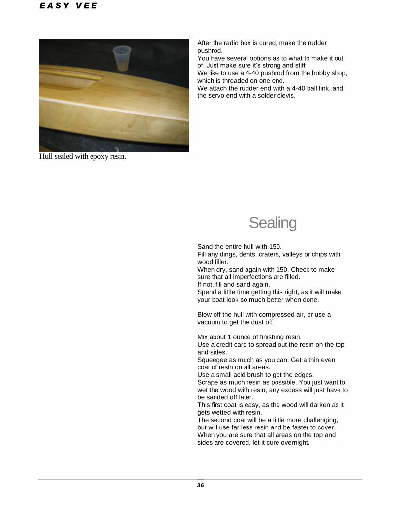
Hull sealed with epoxy resin.
After the radio box is cured, make the rudder pushrod. You have several options as to what to make it out of. Just make sure it’s strong and stiff We like to use a 4-40 pushrod from the hobby shop, which is threaded on one end. We attach the rudder end with a 4-40 ball link, and the servo end with a solder clevis.
Sealing Sand the entire hull with 150. Fill any dings, dents, craters, valleys or chips with wood filler. When dry, sand again with 150. Check to make sure that all imperfections are filled. If not, fill and sand again. Spend a little time getting this right, as it will make your boat look so much better when done. Blow off the hull with compressed air, or use a vacuum to get the dust off. Mix about 1 ounce of finishing resin. Use a credit card to spread out the resin on the top and sides. Squeegee as much as you can. Get a thin even coat of resin on all areas. Use a small acid brush to get the edges. Scrape as much resin as possible. You just want to wet the wood with resin, any excess will just have to be sanded off later. This first coat is easy, as the wood will darken as it gets wetted with resin. The second coat will be a little more challenging, but will use far less resin and be faster to cover. When you are sure that all areas on the top and sides are covered, let it cure overnight.
E A S Y V E E
37
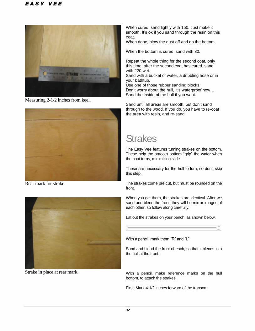
Measuring 2-1/2 inches from keel.
Rear mark for strake.
Strake in place at rear mark.
When cured, sand lightly with 150. Just make it smooth. It’s ok if you sand through the resin on this coat. When done, blow the dust off and do the bottom. When the bottom is cured, sand with 80. Repeat the whole thing for the second coat, only this time, after the second coat has cured, sand with 220 wet. Sand with a bucket of water, a dribbling hose or in your bathtub. Use one of those rubber sanding blocks. Don’t worry about the hull, it’s waterproof now… Sand the inside of the hull if you want. Sand until all areas are smooth, but don’t sand through to the wood. If you do, you have to re-coat the area with resin, and re-sand.
Strakes The Easy Vee features turning strakes on the bottom. These help the smooth bottom “grip” the water when the boat turns, minimizing slide.
These are necessary for the hull to turn, so don’t skip this step.
The strakes come pre cut, but must be rounded on the front.
When you get them, the strakes are identical. After we sand and blend the front, they will be mirror images of each other, so follow along carefully.
Lat out the strakes on your bench, as shown below.
With a pencil, mark them “R” and “L”.
Sand and blend the front of each, so that it blends into the hull at the front.
With a pencil, make reference marks on the hull bottom, to attach the strakes.
First, Mark 4-1/2 inches forward of the transom.
E A S Y V E E
38
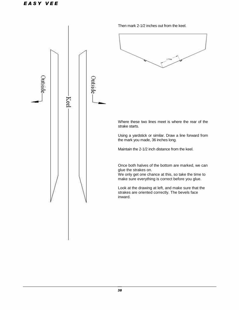
Then mark 2-1/2 inches out from the keel.
Where these two lines meet is where the rear of the strake starts.
Using a yardstick or similar. Draw a line forward from the mark you made, 36 inches long.
Maintain the 2-1/2 inch distance from the keel.
Once both halves of the bottom are marked, we can glue the strakes on. We only get one chance at this, so take the time to make sure everything is correct before you glue. Look at the drawing at left, and make sure that the strakes are oriented correctly. The bevels face inward.
E A S Y V E E
39
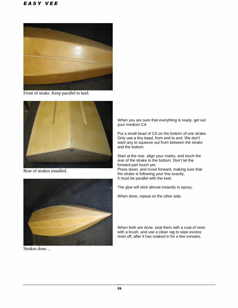
Front of strake. Keep parallel to keel.
Rear of strakes installed.
Strakes done…
When you are sure that everything is ready, get out your medium CA Put a small bead of CA on the bottom of one strake. Only use a tiny bead, from end to end. We don’t want any to squeeze out from between the strake and the bottom. Start at the rear, align your marks, and touch the rear of the strake to the bottom. Don’t let the forward part touch yet. Press down, and move forward, making sure that the strake is following your line exactly. It must be parallel with the keel. The glue will stick almost instantly to epoxy. When done, repeat on the other side. When both are done, seal them with a coat of resin with a brush, and use a clean rag to wipe excess resin off, after it has soaked in for a few minutes.
E A S Y V E E
40
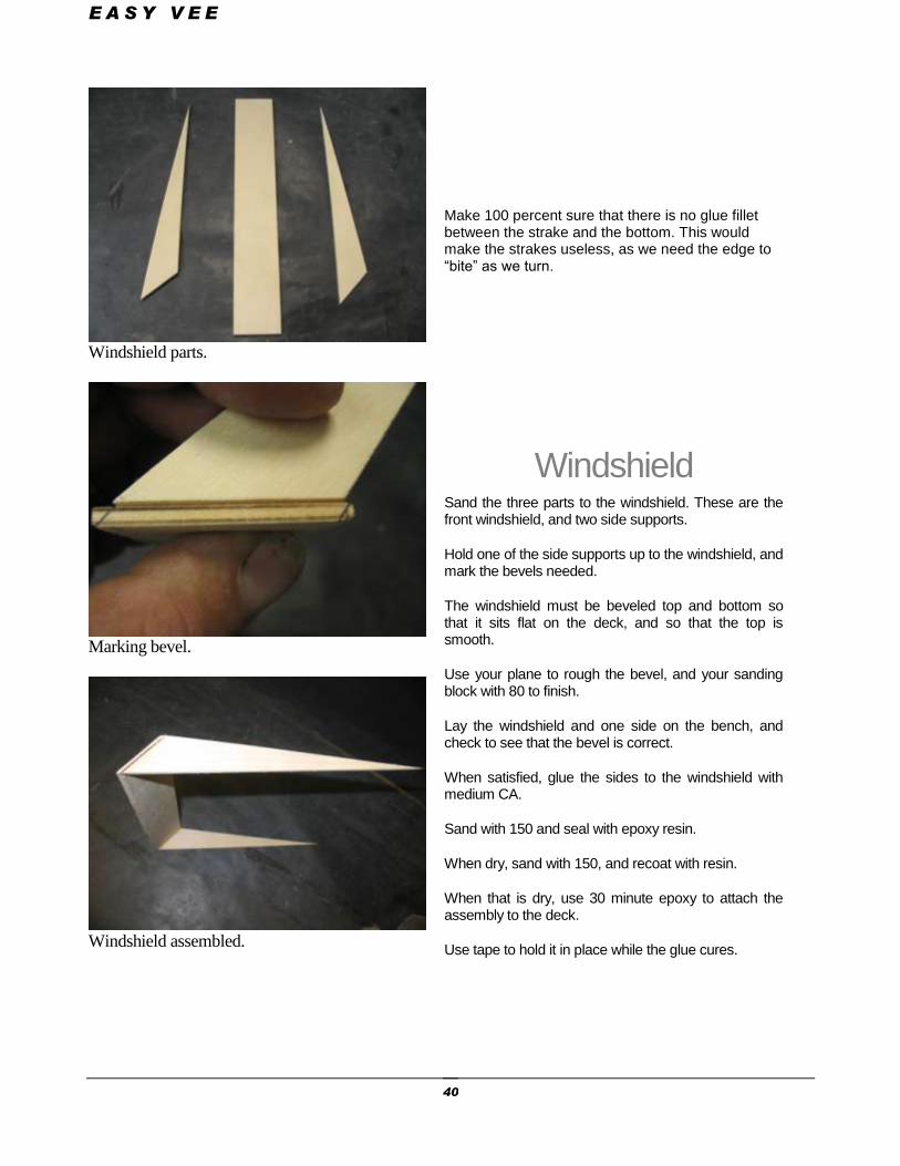
Windshield parts.
Marking bevel.
Windshield assembled.
Make 100 percent sure that there is no glue fillet between the strake and the bottom. This would make the strakes useless, as we need the edge to “bite” as we turn.
Windshield Sand the three parts to the windshield. These are the front windshield, and two side supports.
Hold one of the side supports up to the windshield, and mark the bevels needed.
The windshield must be beveled top and bottom so that it sits flat on the deck, and so that the top is smooth.
Use your plane to rough the bevel, and your sanding block with 80 to finish.
Lay the windshield and one side on the bench, and check to see that the bevel is correct.
When satisfied, glue the sides to the windshield with medium CA.
Sand with 150 and seal with epoxy resin.
When dry, sand with 150, and recoat with resin.
When that is dry, use 30 minute epoxy to attach the assembly to the deck.
Use tape to hold it in place while the glue cures.
E A S Y V E E
41
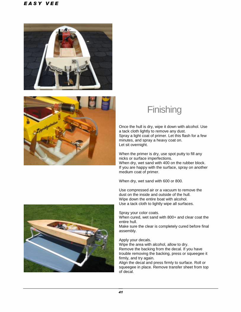
Finishing
Once the hull is dry, wipe it down with alcohol. Use a tack cloth lightly to remove any dust. Spray a light coat of primer. Let this flash for a few minutes, and spray a heavy coat on. Let sit overnight. When the primer is dry, use spot putty to fill any nicks or surface imperfections. When dry, wet sand with 400 on the rubber block. If you are happy with the surface, spray on another medium coat of primer. When dry, wet sand with 600 or 800. Use compressed air or a vacuum to remove the dust on the inside and outside of the hull. Wipe down the entire boat with alcohol. Use a tack cloth to lightly wipe all surfaces. Spray your color coats. When cured, wet sand with 800+ and clear coat the entire hull. Make sure the clear is completely cured before final assembly. Apply your decals. Wipe the area with alcohol, allow to dry. Remove the backing from the decal. If you have trouble removing the backing, press or squeegee it firmly, and try again. Align the decal and press firmly to surface. Roll or squeegee in place. Remove transfer sheet from top of decal.
E A S Y V E E
42
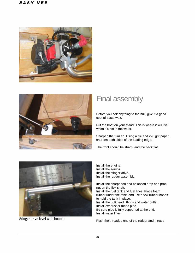
Stinger drive level with bottom.
Final assembly Before you bolt anything to the hull, give it a good coat of paste wax. Put the boat on your stand. This is where it will live, when it’s not in the water. Sharpen the turn fin. Using a file and 220 grit paper, sharpen both sides of the leading edge. The front should be sharp, and the back flat. Install the engine. Install the servos. Install the stinger drive. Install the rudder assembly. Install the sharpened and balanced prop and prop nut on the flex shaft. Install the fuel tank and fuel lines. Place foam rubber under the tank, and use a few rubber bands to hold the tank in place. Install the bulkhead fittings and water outlet. Install exhaust or tuned pipe. Be sure pipe is fully supported at the end. Install water lines. Push the threaded end of the rudder and throttle
E A S Y V E E
43
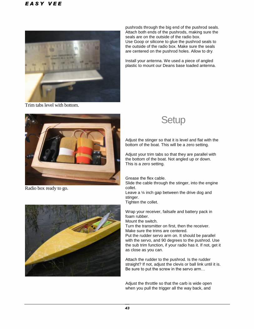
Trim tabs level with bottom.
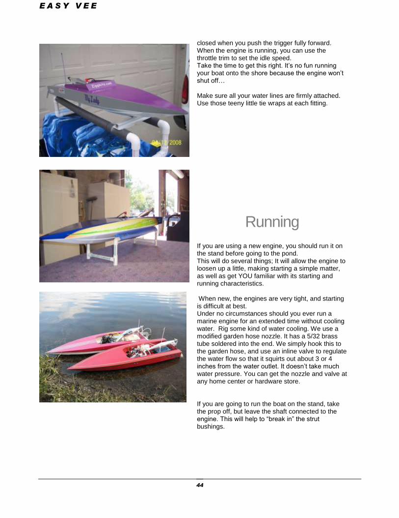
Radio box ready to go.
pushrods through the big end of the pushrod seals. Attach both ends of the pushrods, making sure the seals are on the outside of the radio box. Use Goop or silicone to glue the pushrod seals to the outside of the radio box. Make sure the seals are centered on the pushrod holes. Allow to dry.
Install your antenna. We used a piece of angled plastic to mount our Deans base loaded antenna.
Setup Adjust the stinger so that it is level and flat with the bottom of the boat. This will be a zero setting. Adjust your trim tabs so that they are parallel with the bottom of the boat. Not angled up or down. This is a zero setting. Grease the flex cable. Slide the cable through the stinger, into the engine collet. Leave a ¼ inch gap between the drive dog and stinger. Tighten the collet. Wrap your receiver, failsafe and battery pack in foam rubber. Mount the switch. Turn the transmitter on first, then the receiver. Make sure the trims are centered. Put the rudder servo arm on. It should be parallel with the servo, and 90 degrees to the pushrod. Use the sub trim function, if your radio has it. If not, get it as close as you can. Attach the rudder to the pushrod. Is the rudder straight? If not, adjust the clevis or ball link until it is. Be sure to put the screw in the servo arm… Adjust the throttle so that the carb is wide open when you pull the trigger all the way back, and
E A S Y V E E
44
closed when you push the trigger fully forward. When the engine is running, you can use the throttle trim to set the idle speed. Take the time to get this right. It’s no fun running your boat onto the shore because the engine won’t shut off… Make sure all your water lines are firmly attached. Use those teeny little tie wraps at each fitting.
Running If you are using a new engine, you should run it on the stand before going to the pond. This will do several things; It will allow the engine to loosen up a little, making starting a simple matter, as well as get YOU familiar with its starting and running characteristics. When new, the engines are very tight, and starting is difficult at best. Under no circumstances should you ever run a marine engine for an extended time without cooling water. Rig some kind of water cooling. We use a modified garden hose nozzle. It has a 5/32 brass tube soldered into the end. We simply hook this to the garden hose, and use an inline valve to regulate the water flow so that it squirts out about 3 or 4 inches from the water outlet. It doesn’t take much water pressure. You can get the nozzle and valve at any home center or hardware store. If you are going to run the boat on the stand, take the prop off, but leave the shaft connected to the engine. This will help to “break in” the strut bushings.
E A S Y V E E
45
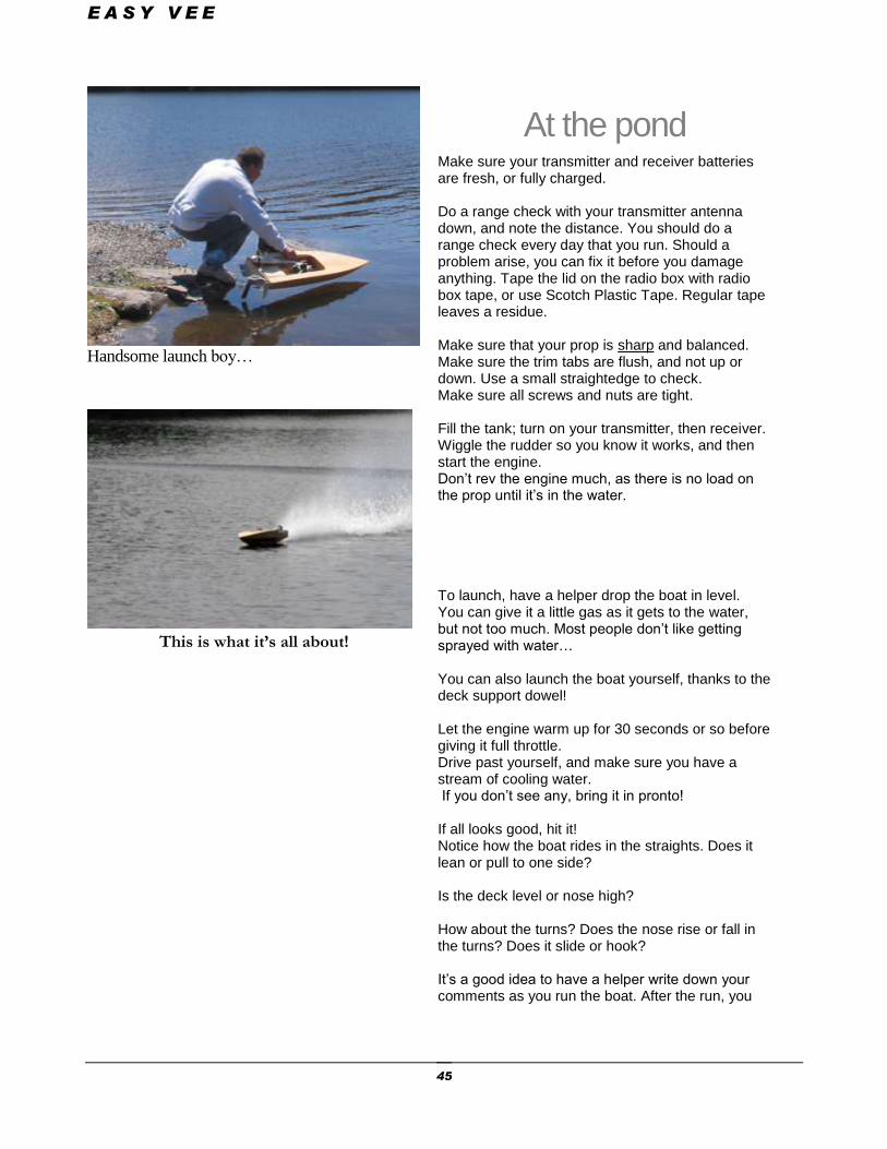
Handsome launch boy…
This is what it’s all about!
At the pond Make sure your transmitter and receiver batteries are fresh, or fully charged. Do a range check with your transmitter antenna down, and note the distance. You should do a range check every day that you run. Should a problem arise, you can fix it before you damage anything. Tape the lid on the radio box with radio box tape, or use Scotch Plastic Tape. Regular tape leaves a residue. Make sure that your prop is sharp and balanced. Make sure the trim tabs are flush, and not up or down. Use a small straightedge to check. Make sure all screws and nuts are tight. Fill the tank; turn on your transmitter, then receiver. Wiggle the rudder so you know it works, and then start the engine. Don’t rev the engine much, as there is no load on the prop until it’s in the water. To launch, have a helper drop the boat in level. You can give it a little gas as it gets to the water, but not too much. Most people don’t like getting sprayed with water… You can also launch the boat yourself, thanks to the deck support dowel! Let the engine warm up for 30 seconds or so before giving it full throttle. Drive past yourself, and make sure you have a stream of cooling water. If you don’t see any, bring it in pronto! If all looks good, hit it! Notice how the boat rides in the straights. Does it lean or pull to one side? Is the deck level or nose high? How about the turns? Does the nose rise or fall in the turns? Does it slide or hook? It’s a good idea to have a helper write down your comments as you run the boat. After the run, you

E A S Y V E E
46
can use the included” Tuning Tools” sheet to help you sort out any problems. Have fun, be safe, and send us your pictures! Send pics and videos to [email protected]

E A S Y V E E
47
Troubleshooting
Boat bounces in the straights- Stinger angled up CG too far back Speed too slow Boat blows over at high speed- CG too far back Stinger angled up Inner tabs too high Boat “plows”- CG too far forward Stinger angled down Inner tabs too low Boat is very “light” and unstable- Inner tabs too high Stinger drive too deep Boat needs left trim to go straight- Prop walk Prop walk Prop walk Rudder not aligned correctly Prop walk Boat slides too much in turns- CG too far forward Turn fin too small Boat hooks in turns- CG too far back Turn fin too big Rudder angled back Boat “chine walks”- Center tabs too high Stinger too deep Boat “heels” right with power- Right inner tab too high Boat leans too far and turns Rudder angled left poorly Boat is slow and won’t turn- Get a Zippkits boat!
E A S Y V E E
48
Race Setup
With many people racing their EV’s, we have some great setup tips. The EV should be able to handle a stock or mild Zenoah
and turn tight on the buoys…
Stinger-
Set the centerline of the prop shaft 1/2 inch above the bottom of the hull. This allows the boat to settle in the water a little, calming it down.
Set the stinger level with the bottom of the boat. Trim this down if the nose runs high in the straights.
Trim Tabs-
Set all tabs straight. Adjust RH inner tab to make hull ride level (side to side, not leaning)
Make the RH outer tab the same as the inner, then adjust down to tighten right turns. Adjust LH inner so that hull chine walks slightly in the straights.
Adjust LH outer for best left turns.
Try different props-
We like the Zipp 470, Zipp 670, Prather 270, 275 or Octura X670 for a stock engine. Try different props to get the handling you want.
The Easy Vee responds well to small 3 blade props like 6518 and 2514.
Pull the pipe in-
Once you get the boat handling the way you want, pull the tuned pipe in by 1/8 inch increments. If the engine seems to “bog” going into, or out of turns, pull the pipe out
slightly until it doesn’t.


