A.1A38 10 IMPLEMENTING PC (LNEAR PREDICTIVE COOING) ALGORITHMS l THESTUDY OF SP,.U AIRFORCE INST OF TECH SITRIGHT-PATTERSON AFB OH SCHOOL OF ENGI. C E MCKOWN mNLSE Eh3AI/EE hE8D-4hh 9/hE ELEMEh~hE
Transcript
A.1A38 10 IMPLEMENTING PC (LNEAR PREDICTIVE COOING) ALGORITHMS lTHESTUDY OF SP,.U AIRFORCE INST OF TECH
SIT RIGHT-PATTERSON AFB OH SCHOOL OF ENGI. C E MCKOWN
mNLSE Eh3AI/EE hE8D-4hh 9/hE
ELEMEh~hE
g 132 2
NANLBi ~ A AO~ll A
ACb
DIC
IEPREMENTING LPC ALG ORTHMS
AIN THRE ISTIUDY O PEHERCESSNGLG
Di2LTuio UnSiite
DTIC
AFIT/GE/EE/83D-4 5
Accession For
NTIS(AIDTIC TABUnannovuneed
JUStificntio.n
By
Distribution/
Availability Codes
Avail and/or
Dist Special
D?,c
II
IMPLEMENTING LPC ALGORITHMSIN THE STUDY OF SPEECH PROCESSING
THESIS
AFIT/GE/EE/8 3D-4 5
CRAIG E. McKOWN2LT USAF
DTICI I ELE2CTL.
SEB 2 2 184j
D
As-4k
. Approved for public release; distribution unlimited
WO-
AFIT/GE/EE/83D-45
IMPLEMENTING LPC ALGORITHMS IN THE STUDY OF SPEECH
PROCESSING
THESIS
Presented to the Faculty of the School of Engineering
of the Air Force Institute of Technology,
Air University
*in Partial Fulfillment of the
Requirements for the Degree of
Master of Science in Electrical Engineering
by
Craig E. McKown
2Lt USAF
Graduate Electrical Engineering
December 1983
4A
, Approved for public release; distribution unlimited
PREFACE
Digital Voice Communication is a pervasive phenomenon
in our society. Without even noticing it we carry on phone
conversations over a digital channel. So, why is digital
communication so widely used? One reason is that the
digital speech signals can be made more noise immune or even
secure than the analog signals. Another reason is the
advanced development in integrated circuit technology, which
allows easier implementation of digital processing
techniques. Whatever the case, the field of digital
communication is an exciting field and one which I feel is
expanding. Therefore, I am glad that I could prepare my
thesis under this topic.
Linear Predictive Coding is one facet of the field of
digital communication. The goal of the coding is to reduce
the bit rate of the signal sent over the communication
channel. The system I developed does not reduce the bit
rate very much, but then it is not a true communication
system. It is a computer simulation of such a system, which
will give the user an opportunity to explore some of the
ideas, methods, and problems of LPC.
Since the system developed here is a tool, the most
important product of the thesis may well be the user's
guide. It presentq the programs and demonstrates how a
student may actually process speech through an LPC system.
ii
But let me not forget those who made it possible for me
to finish this project and receive my degree. I must thank
my thesis advisor, Major Larry Kizer, who presented me with
the project and let me develop it in my own way.
I wish to thank my readers, Dr. Matthew Kabrisky and
Major Kenneth Castor. I also thank Dan Zambon for keeping
Bertha, the computer operating most of the time.
I also need to thank Capt Willis Janssen for tolerating
me those late nights in the summer when we hacked away until
midnight trying to debug code.
I am also indebted to my roommate, Chuck Lutes, who let
me use his computer to write this thesis.
Craig E. McKown
4gW
~iii
TABLE of CONTENTS
PAGE
Preface Bn ...... ................................. ...... ii
Table of Contents.............................iv
List of Figuress................. .. ............ . ....... vi
List of Tables ......... d............................ vii
ArAbstract ................. o........ ............ ... ...... viii
I Introduction Meth.................. ....... . I-8
Background ............. ....................... 11-9Statement of the Problem ...................... I-4Scope ... .. . . . . . . . . . . . . . . . . . -
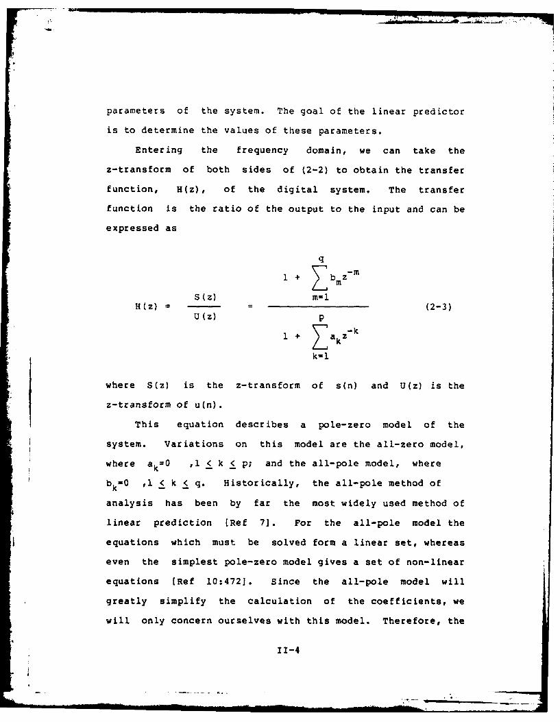
Derviptio of the LPCte .........er.............II-5
ID. The Theory of Linear Prediction .............. II-
gain factor (UNGA), and the shape of the glottal pulse
(NGLT)] are then written to the channel file. This completes
the initialization of the system. The rest of the system is
a large loop which is repeated until the input speech data
is exhausted.
The first order of business within the loop is to load
a large array with five blocks of speech (each block
contains 256 samples) from the contiguous input file. This
large array is needed because this data is written to two
small arrays, one used for pitch detection, and one used for
111-5
predictor coefficient generation. Each array contains one
frame of speech. The length of each frame is set by a
decision variable (MAXFR). The large size is so that a wide
range of frame sizes can be used by the analyzer.
Using counters to keep track of where the process is in
terms of blocks and array members, a portion of the large
array is written to a smaller array. This smaller array
contains one frame of speech to be processed for energy and
pitch. This frame is first processed by the energy
subroutine. This subroutine finds the energy (sum of the
squares) in the frame to determine if the data can be
considered silence or speech. The test threshold is a
decision variable (THRESH) which is set by the user. The
energy of the frame is a functon of its length, therefore,
if the length of the frame is changed, the decision variable
THRESH should be changed by a proportional amount to
maintain consistent results. If the threshold is not
exceeded, the signal is considered silence, and no more
calculations need be made on this frame. The subroutine has
a memory of three previous energy calculations. The need for
the memory will become apparent when the nature of the pitch
detection and the synchronous nature of the analysis is
discussed.
If the frame has sufficient energy to be considered
speech and not background noise, the pitch is then
calculated. The pitch detection routines perform two tasks:
determining the voiced quality of the speech (whether the
111-6
L
frame is voiced or not), and then the pitch of the speech if
the frame is voiced. The frame for pitch is moved at an
interval (MAXPT) which is set by the user. Pitch is
therefore updated every MAXPT samples and is assumed
constant over the frame.
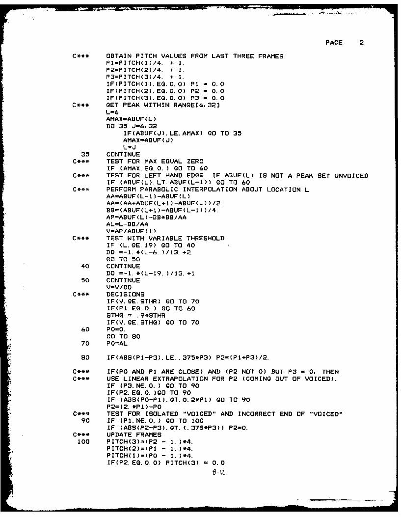
One method of pitch detection is essentially a
correlation process. The frame array is correlated against
itself, and the peaks which fall within an allowable range
of times are tested to find a maximum. The maximum peak is
then tested against a threshold which is set by the user.
This threshold is the decision variable STHR. If the
magnitude of the peak falls below the threshold, the speech
is declared unvoiced, otherwise it is declared voiced. The
pitch is a function of the location of the peak. Since the
range of fundamental pitch of most human speakers falls
within a fairly narrow range (70-350 Hz) [Ref 9], only a
narrow range of peak positions need to be considered. Due
to the harmonics and the formant structure of speech, the
pitch period is a difficult calculation and is quite prone
to error. Therefore interpolation is employed to smooth the
curve described by the pitch values.
This interpolation delays the final value of the pitch
by three frames (see figure 3-3). An estimate of the pitch
in the first pitch analysis frame is computed. The frame
start is shifted by the pitch shift interval (MAXPT), and
the pitch of the second frame is estimated. Similarly, the
pitch of the third frame is estimated. These three values
111-7
P~-~ A AV n~v
FAA OIE
TiriE
Figure 3-3 Relationship between pitch analysis frames showinq a 2:1overlap.
111-8
are used to interpolate a better estimate of the pitch in
the first frame. The pitch in the following frames is
determined in a similar manner. For instance, the estimateof the fourth frame is used along with the estimates of he
second and third frame to interpolate a better estimate of
the pitch in the second frame. This delay requires that the
calculation of the predictor coefficients be equivalently
delayed. The pitch detectors must therefore have a memory
of three to perform the interpolation and to accomodate the
delay of the coefficient analysis.
After the pitch is determined by interpolation, the LPC
coefficients and the gain must be calculated. The
coefficient analysis frame can be pre-processed in a number
of different ways. If desired, the speech can be
pre-emphasized. The pre-emphasis is accomplished wih the
operation
y(n) = x(n) - .9x(n-l) (3-1)
The decision variable which controls this is NEMP. Also
available to the user is the option to window the frame. A
decision variable, Hl, controls whether or not a Hamming
window is used on the speech. After pre-processing, the LPC
calculations are straight-forward, and are performed by one
of the algorithms presented in Chapter II. A decision
variable (MP) controls which algorithm to use, and therefore
which subroutine to perform. A decision variable (POLES)
also contols the number of poles used in the analysis. The
system is unable to operate with more than 20 poles, because
111-9
of constraints on the size of some of the arrays. The
predictor coefficients are computed synchronously, that is
the start of the frame used by the coeffiecient generating
routines is set by the shift introduced by the pitch period.
This avoids the problem of having analysis extend over two
adjacent frames.
The last task during processing of each frame is to
write the relevant parameters to the channel file. These
parameters are the voiced quality of the speech, the pitch,
the output analysis frame size, the predictor coefficients,
and the gain of the system. The output analysis frame size
is the shift interval for the start of the next coefficient
analysis frame.
Description of the Synthesizer
The LPC synthesizer produces speech from the parameters
read from a channel file. The first stage of the
synthesizer program opens the channel file and creates the
file to which synthesized speech will be written. The
program is initialized by reading the first four values from
the channel file. These values are the number of poles used
in the analysis and the synthesis (POLES), the glottal pulse
shape (NGLT), the unvoiced gain factor (UNGA), and the value
of the flag indicating whether pre-emphasis was employed at
the input to the analyzer (NEMP). The unvoiced gain factor
is used to normalize the unvoiced excitation to the output
filter. The vocoder then synthesizes one variable length
III-10
iI
frame of speech at a time. The frames have varying length
because of the synchronous method of coding. To synthesize
each frame, the vocoder first reads the pitch information,
the length of the frame to be produced, and the gain. It
then reads the predictor coefficients. The pitch
information drives the synthesis process.
If the frame is voiced, an array simulating the glottal
pulse drives the digital output filter. Two pulses are
generated at intervals separated by the pitch period, and
are written to an array of length twice the period. This
array, the predictor coefficients, and the gain then drive
the subroutine NTHROAT" which is the digital output filter.
The output of this filter is the synthesized speech and is
written to the output file.
If the frame is unvoiced, a noise generation routine is
called. This double-precision routine uses a uniform random
number generator to produce a normal random number sequence.
This routine writes the sequence to an array. The gain from
the input file is scaled by the unvoiced gain factor to give
a value for the gain to drive the digital output filter.
This scaling is required because the excitation of the
filter (the noise array) is not normalized in energy with
the excitation of the filter when the speech is voiced.
This array, the predictor coefficients, and the gain then
drive the digital output filter. The output of this filter
is the synthesized speech, which is written to the output
file.
* 111
:>2
If the frame is silence, the output filter is by-passed
and zeros are written directly to the output file.
If pre-emphasis was used by the analyzer, then
de-emphasis must be employed before the speech is written to
the output file. The inverse function of the pre-emphasis
is used for this
y(n) = x(n) + .9y(n-l) (3-2)
The speech is finally scaled so that it can be listened to
by using the "AUDIOHIST" or "AUDIOMOD" programs.
Synchronous Analysis
The LPC system developed in this thesis uses a
synchronous method of analysis. Synchronous analysis
requires an update of the predictor coefficients once every
pitch period (see figure 3-4). Because of the delay in
determining the correct pitch, the predictor coefficients
are generated with a two frame delay with respect to the
pitch detection. The shift interval of the coefficient
analysis is a multiple of the pitch period (P1 in figure
3-3). When the start of an analysis frame falls after the
start of the next pitch detection frame, the value of this
pitch (P2 ) is used as the shift interval. The frame
start is then shifted as before until a new pitch value is
needed. At this point, a new frame is estimated for pitch.
In a synchronous system, analysis on each voiced
segment of speech begins at the beginning of the pitch
period and the analysis frame is shifted at an interval
111-12
...
V- " ... v 1 v v v V . . :
91 --- ---I CA ew
I[- P. - P -P-- -
P, 4P
: ~- - P .
I 7. - -11
~.2, , ,f,.p, ,V,. ,..J f,-.
3f'~ t
Figure 3-4 Relationship between coefficient analysis frames for a
synchronous analysis system.
111-13
which is a multiple of the pitch period (see figure 3-3).
The vocoder only synthesizes the speech between the start of
every analysis frame. For this reason is the analysis frame
size written onto the channel file. Synchronous analysis
avoids the problem of having a pitch period of voiced speech
straddling the boundary between two consecutive frames.
When analysis straddles two frames, the coefficients must be
interpolated for the portion of speech reproduced over the
boundary. The interpolated values of these coefficients are
not guaranteed to give stable results.
During unvoiced speech, the shift interval is constant.
A constant frame rate (MAXFR) is used for shifting the
coefficient analysis.
The three frame delay of the pitch detector requires a
delay of the coefficient analysis by a corresponding time
period. Therefore the frame starts and boundaries of the
pitch analysis frame and the coefficient analysis frame are
different. This is the reason for the memory of the pitch
and energy detectors and the initial large array. With this
$array, the current pitch can be calculated with one portion
of the data, and used for interpolation of past pitch. At
the same time, the delayed pitch can be used to determine
the correct starting locati - in the past for predictor
coefficient generation. Therefore the system can perform
coefficient calculation in step with pitch detection. This
does tend to limit flexibility because it does not allow
asynchronous analysis.
111-14
some complexity is added because of the synchronous
nature of the analysis. For example, the bookkeeping for
each frame is doubly complex; two sets of counters must be
maintained. It is also confusing that the pitch detection
and predictor coefficient generating routines do not work on
the same data simultaneously. This requires that the
predictor coefficient generating routines operate after the
pitch has been calculated for the final frame. Substantial
gains are realized, though, because interpolation of
predictor coefficients need not be performed. Counters
would also have to be maintained in vocoder to mark the
beginning and ending of boundary-overlapping sections of
speech.
Time Constraints
Unfortunately, the system does not run in real-time. A
number of factors affect the speed of the system, among
these: the software implementation, the audio interface, and
the speed of the computer.
The biggest constraint on time is the software in the
system. Since the software is written in a high level
language, its speed is limited by the constraints of the
language. Some of these constraints are the time necessary
to write to a file and the operation rate of the
minicomputer. A hardware implementation would not be under
these constraints. The software is also a bit cumbersome in
that it must be flexible enough to operate properly with
111-15
many different possible prediction schemes. For use in the
laboratory, the transmitter and the receiver programs must
be run sequentially, whereas they would operate in parallel
if in a normal communication configuration.
Another time constraint is that the audio interface in
the lab is not prepared for real time events. The program
which performs the digital to analog calculations and
channel calling routines required to listen to the
synthesized speech must read a file first. The size of this
file is limited by the program to less than three seconds.
Therefore, long utterances are impossible to process and
listen to without interuption and user interaction with the
system.
Summary
The two-program nature of the LPC system is used to
imitate the tranmitter and receiver nature of a true
communication link. These two programs are the LPC analyzer
and the LPC synthesizer. The channel between them is a file
written in the memory of the computer. Subroutines are used
extensively to permit easy examination of internal results
and provide flexibility to run or add different subroutines
which perform the same analysis in different ways.
Synchronous analysis is employed to simplify synthesis of
the output speech.
111-16
CHAPTER IV
Testing and Results
The System
This thesis designed an LPC speech processing system
which operates in the Signal Processing Laboratory at the
Air Force Institute of Technology. It is an operational
model and replicates a number of aspects of a true LPC
speech communication system. Unfortunately, this system
does not run in real time, as it is written entirely in
software and must access and write files which reside in the
minicomputer's memory. A real LPC processor and synthesizer
would receive and transmit signals over a communication
channel, and except for buffering, would require no reading
or writing from files. Most of these operations would be
handled by more time-efficient hardware.
A simple test of the system consists of actually
processing an utterance. Each utterance is a digitized
version of a sentence spoken by a human. These utterances
or speech files are relatively noise-free so that the noise
problem of LPC would not need to be considered. These
utterances were successfully processed by the system to give
intelligible results.
To demonstrate the flexibility of the system, various
combinations of shift intervals, analysis window size,
prediction methods, pitch detection algorithms, and
IV-l
threshold values were tested. The results of these
combinations indicate that the system is flexible. Table
4-1 shows the allowable ranges of the decision variables.
The recommended values on this table indicate values for the
decision variables which seemed the give the best results.
Other testing showed that with only a very few exceptiops,
the system could handle all of the combinations with which
it was tested. The exceptions are noted below.
On occasion, especially when a low pitched voice was
processed, the vocoded speech was so unintelligible that it
was impossible to determine that an utterance was present.
This problem arises from the nature of the synchronous
analysis. Synchronous analysis demands that two shift
intervals be maintained, one for the pitch analysis window
and one for the coefficient analysis window. During voiced
speech, the shift interval for the coefficient analysis
window is based on the pitch period, but the bookkeeping
counters are based on the shift interval of the pitch
detector. If the shift interval is less than the length of
the longest pitch period during voiced speech, the analysis
window used to calculate the prediction coefficient is
incorrectly bounded. Results in this case are consistently
poor, and result in unstable filters which produce
unintelligible clicks, buzzes, and squeals. To eliminate
this problem, the frame shift interval must be increased to
accomodate the lowest pitch frequency of the file. For the
file which contained the lowest pitch this interval is
IV-2
Table 4-1
Ranges of the Decision Variables
Decision Lower Upper RecommendedVariable Limit Limit Value
POLES 6 20 16MP a - - 1MAXFR 100 400 200MAXPT b 80 200 100NEMP a - - 1NGLT a - - 3H1 a - - 1MPCH a - - 0NPCS a - - 1STHR 0.0 1.0 0.35SCAF 1.0 1000.0 1.0THRESH 0.0 1000000.0 250.0UNGA 0.001 100.0 0.1
a) These variables are flags which determine whethersubroutines will be performed or not. They do not haveupper or lower limits over a range.
b) It is recommended that the value of MAXPT be half thevalue of MAXFR. This gives a 2:1 overlap.
IV-3
between 80 and 100 samples.
Two methods of predictor coefficient generation are
included in the system and were examined extensively. Both
give acceptable results and produce intelligible speech at
the output. Although theory indicates that the covariance
method of prediction need not be windowed, much better
results are attainable when the incoming speech signal is
weighted by a Hamming window. In this context, better
results mean higher quality. Without the windowing, the
method often produces unstable output filters. With the
windowing, the resultant speech exceeded the quality of
spech produced with the autocorrelation method.
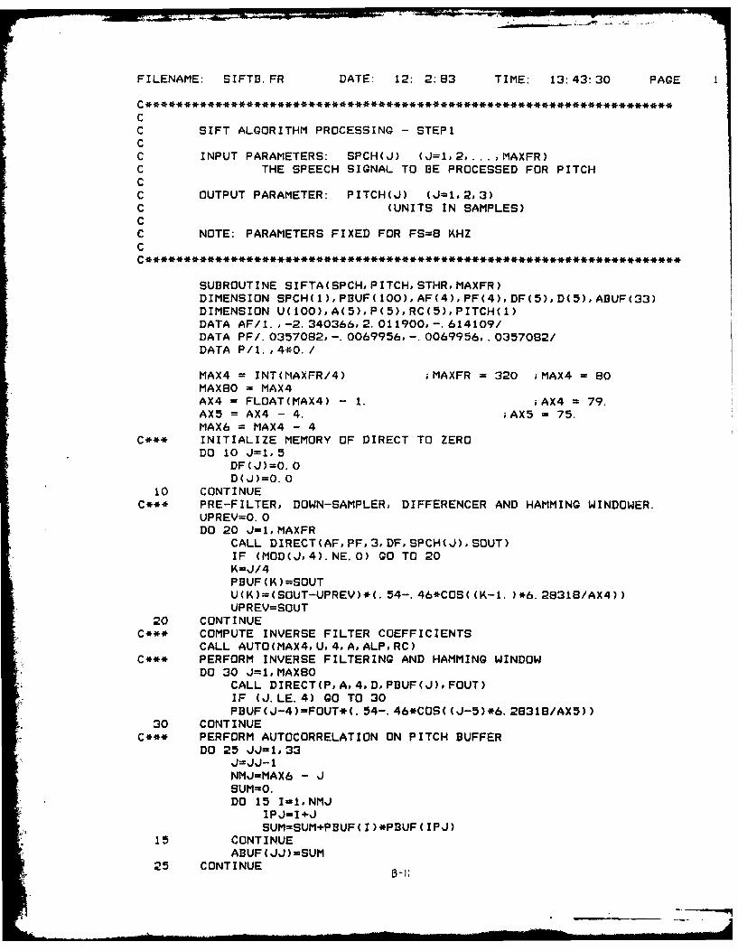
The Sift routine [Ref 9,10] for pitch detection was the
only satisfactory pitch detector implemented. The Sift
algorithm uses an inverse filtering technique to cancel the
effect of the formant structure. In a non-noise
environment, this detector can consistently differentiate
between voiced and unvoiced speech It can also successfully
determine the pitch to produce natural sounding speech. An
autocorrelation method was also examined but the algorithm
did not give consistent results. The calculated pitch was
monotone except for a disconcerting waver.
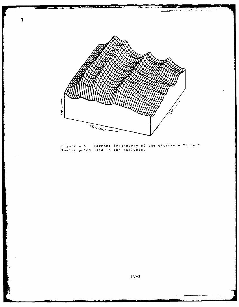
The number of poles in the analysis was also varied.
Ten poles marked a qualitative boundary between clear speech
and muffled speech. Using too few poles gave vocoded speech
which was severely muffled. With such a small number of
poles the filter does not have the resolution required to
IV-4
• 71
describe the complete formant structure of the modeled vocal
tract (see figures 4-1 to 4-5). With less than six poles,
the speech becomes unintelligible. With more than ten
poles, the quality of the resultant speech increases with
the addition of poles, with maximum quality reached at about
sixteen poles. With sixteen or more poles, the quality
remains approximately the same.
Noise
The noise was introduced to each utterance by adding a
random noise signal to the file containing the utterance.
This was accomplished with the same random noise generating
subroutine which is used to excite the vocoder during
unvoiced speech. A separate program performs this noise
addition. The maximum value of the noise can be varied to
provide noise levels from zero to considerably in excess of
the speech power. Because speech is not a stationary
process, a true signal to noise level is difficult to
calculate. It varies widely if the noise level is constant
because the speech energy varies widely from low energy in
the fricatives (s,sh,f,th...) to much higher energy in the
voiced sounds such as vowels. For our concerns, a signal to
noise ratio (SNR) was determined by calculating the power of
the noise and comparing it to the power of the voiced
portion of a clean file. Although the true SNR may vary
from frame to frame and from speech file to speech file,
consistent results are possible. That is, equivalent
IV-5
T.~
K
Figure 4-1 Formant Trajectory of the utterance "five."Four poles used in the analysis.
Figure 4-2 Formant Trajectory of the utterance "five."Six poles used in the analysis.
IV-6
Figure 4-3 Formant Trajectory of the utterance "five."Eight poles used in the analysis.
Figure 4-4 Formant Trajectory of the utterance "five."Ten poles used in the analysis.
iv-7
Figure 4-5 Formant Trajectory of the utterance "five.
Twelve poles used in the analysis.
IV- 8
values of added noise gave approximately the sa-e SNR to all
cases (see table 4-2) and the synthesized speech suffered
the same problems of unintelligibilty.
Table 4-2
Noise
Maximum Value of Noise Power in Signal to NoiseAdded Noise the Frame (dB) Ratio-SNR (dB)
0 58 20100 61 16200 64 14500 70 8
1000 73 4
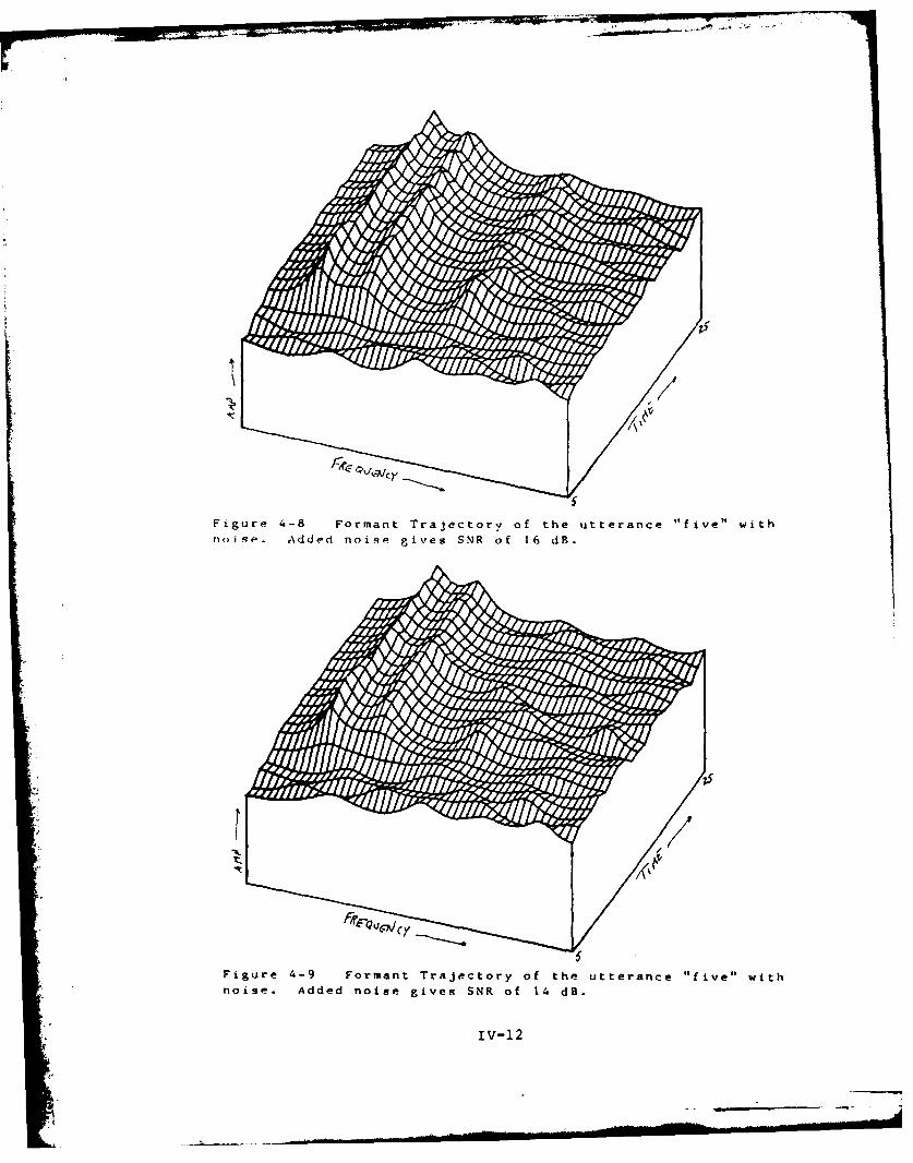
To test the effects of noise, speech files with
different signal to noise ratios were tested. Degradation
occured even with fairly small amount of added noise (SNR =
16dB). Severe degradation of the re-synthesized speech
occured with a SNR of about 8dB for the noisy input signal.
At this level, the output was unintelligible.
The analyzer consists of two parts, a pitch detector
and a prediction coefficient generating routine. These two
parts were examined to determine which is the more sensitive
to noise corruption. This was accomplished by processing
two versions of the same utterance, one which was an
unaltered version of the original speech file, and one which
was the original file plus an amount of random noise added.
These files were processed separately wihin the same
program, one for pitch and the other for the prediction
coefficients. Preliminary results indicate that the
IV-9
predictor coefficients are more susceptible to noise than is
the pitch detection.
With this processing scheme, four permutations of noisy
and clean files are possible. Two permutations use the same
file for pitch detection and coefficient generation. One
performs pitch detection on a clean file and coefficient
generation on a noisy file, and one performs pitch detection
on a noisy file and coefficient generaton on a clean file.
The clean/clean test was used as a control example and
the other permutations were examined for a qualitative
analysis of intelligibility. The signal to noise ratio was
maintained constant over all of the files. Noisy speech
files with a SNR of 8dB gave unintelligible results but were
identifiable as speech, so this level was used as the noisy
file. The mixed analysis (noisy/clean, clean/noisy) gave
interesting results. The noisy coefficient/clean pitch gave
highly degraded speech which was only slightly better than
the noisy/nolisy analysis. Contrasting with this, the clean
coefficient/noisy pitch gave only slightly degraded results.
Three of the five tests were noticably degraded, yet still
intelligible. Two were virtually indistiguishable from the
clean/clean example. It was expected that the noise would
degrade the pitch detection severely and render any
reproducton unintelligible. In the five tests, this was not
the case: the predictor coefficient generating algorithm
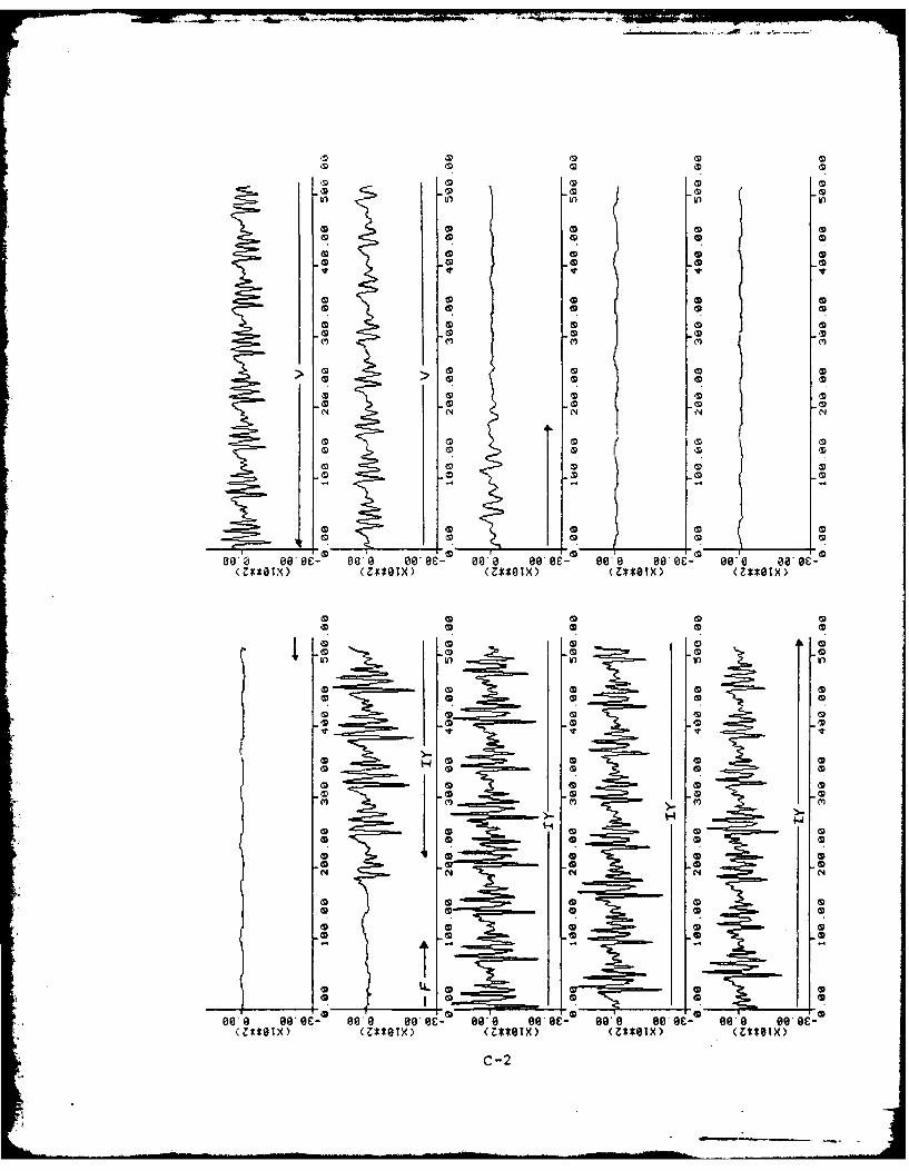
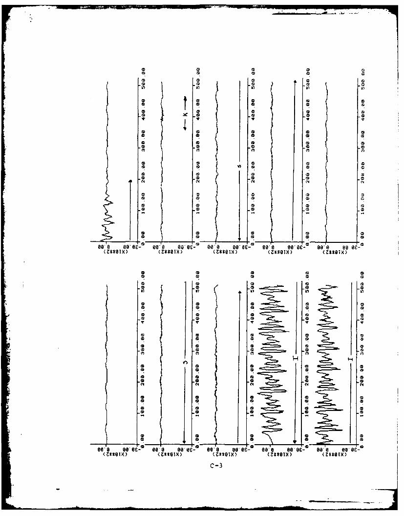
failed. This can be heard in the output speech and seen in
a plot of the frequency response of the ensemble of the
IV-lO
Figure 4-6 Formant Trajectory of the Utterance "five."
Ten poles used in thp analysis. Frames 1-50 shown.
Figure 4-7 Formant Trajectory of the utterance "five." No
added noise. Frames 2-25 shown. (SNR m20 dB).
'V-11
Figure 4.-8 Formant Trajectory of the utterance "five" with
noise. Added noise gives SNR of 1 dB.
IV-12
FR FOICA]f
Figure 4-10 Formant Trajectory of the utterance "five" wit'noise. Added noise gives SNR of 8 dB.
Figuire '.-tl Formant Trajectory of the utterance "five" with
noisp. Addled noise gives SNR of 4 dR.
iv-13
digital filters (figures 4-6 to 4-11). The formant
structure is lost in the noise; only the first formant can
be located and identified on these plots.
To further examine this phenomenon, the glottal pulse
excitation of the outp - filter was replaced by the random
noise excitation. The results in this case sounded like a
whispered utterance, but were still intelligible. In fact,
preliminary results indicate that in a high noise
environment, intelligibility can be gained by neglecting
pitch information at the output and generate the utterance
with only only a random excitation to the output filter.
The waveshape of the synthesized speech was examined to
possibly locate the source of the unintelligibilty. It was
determined that the voiced frames in the synthesized speech
are the main cause of the squeals and buzzes which make the
speech unintelligible.
IV-14
CHAPTER V
Conclusions and Recommendations
Conclusions
This report describes a system which processes speech
using linear predictive methods. The system is a software
simulation of an LPC analyzer and synthesizer. The system
consists of two programs, one of which processes the speech
to generate the LPC parameters, and another which processes
these parameters to resynthesize the speech. An important
aspect of the system is that it enables the user to select
from various pitch and coefficient analysis methods. It
also allows the user to vary other parameters in order to
simulate other changes in the processing scheme.
To test the operation of the system, a regimen of
testing was performed by varying the different parameters.
A separate program allows a simple method for changing all
of the parameters over which the user has control. These
parameters are called the decision variables and each has an
allowable range of values. The system operated
satisfactorally over all values of the decision variables.
The flexibilty exhibited by the system in this testing
indicates that the system can be a valuable tool for the
study of linear predictive coding of speech in the Signal
Processing Lab at AFIT.
Some of the parameters which were tested extensively
V-I
were the number of poles in the analysis, the different
methods of analysis and pitch detection. It was determined
that ten poles give a reasonable representation af speech.
The covariance method of detection exceeded the
autocorrelation method with respect to quality of output
speech. The SIFT pitch detection routine far exceeded the
AUTOC method in determining pitch.
Also examined were some of the noise problems of LPC.
Various noise levels were tested to determine at which level
noise corruption rendered the LPC system useless. This
level was found to be at a signal to noise ratio of about
8dB. Another important result was that the coefficient
generation was greatly affected by noise. The effect of the
predictor coefficients was much greater than the effect of
the pitch detection. This result may be useful in exploring
techniques to counter the effects of noise corruption.
Recommendations
The linear predictive coding system presented in this
thesis can be used as a firm foundation for more study in
the process of linear predictive coding of speech.
Continuing effort with this project could extend in two
general directions. One direction would be software
oriented with further work being done to expand the system
with more subroutines. The other general direction is
oriented to studying more about LPC using the system as a
tool.
V-2
Further Work in Software Development
Part of the flexibilty of the system stems from the
extensive use of subroutines. Additional subroutines could
be incorptrated into the system to expand the present
capabilities of the LPC anlyzer. Perhaps the first task to
be attempted would be to incorporate the recursive LPC
method as developed by Capt Willis Janssen [Ref 4] into this
system. This would offer an opportunity to compare this
method with some of the more common techniques which have
been implemented in the current system. A lattice
formulation of the predictor coefficients would offer
another method of analysis. This method is decribed in the
book by Rabiner and Schafer [Ref 101. An undebugged version
of a possible subroutine implementation is presented in
Appendix D.
Other useful additions to the present system would be
additional pitch detection methods. The AUTOC method might
be altered slightly to give better results. The current
literature describes other methods of pitch detection. The
system would be greatly enhanced if it offered the
availablity of more methods with which to analyze the input
speech signal.
A process for simulating the bit rates actually
transmited over the channel would be a useful addition. At
present, all quanization is done in 2 byte (16 bit)
segments. The coefficients sent over the channel are 4 byte
V-3
floating point words. The flags sent over the channel
require at most 2 bits each, but each is quantized as 16 bit
integers. The pitch is likewise represented as a 16 bit
integer. It could easily be represented with fewer bits.
The frame size information sent over the channel is
redundant and could be eliminated. All of these
compressions could reduce the effective bit rate of the
communicated signal.
Also needed is a better interface with the audio input
and output. The present means to listen to processed speech
is to move the file containing the speech to another
directory (on a different system even) and invoke another
program. This method is time consuming and reduces the
effectiveness of a synthesize-listen-compare atmosphere of
testing.
Further Testing
Since this simulation was designed as a tool to study
the process of linear predictive coding of speech, it seems
only natural that considerable further testing can be
imagined. A fine place to start further research is with
the ubiquitous noise problem.
A possible technique for reducing the effect of noise
was discovered in this work. The technique is to ignore the
pitch detector information. If all speech is presumed to be
unvoiced, the synthesized speech will resemble whispered
speech. In noise, the greatest difference between the input
V-4
speech and the output speech occured during periods of the
utterance declared to be voiced speech. I recommend this
technique to be further explored.
Dr Kabrisky is interested in a method of compressing
the formant frequencies while maintaining the ratio between
them. This system models the human speech production system
with the poles of a digital filter. These poles describe
the formant locations. Therefore digital processing
techniques could be used to shift the poles and consequently
the formants.
One final recommendaton is to use this system as a
means to study the speech recognition capabilities of LPC.
Other research has shown the feasibilty of LPC for speech
recognition tasks [Ref 2]. The feature vector as described
by the predictor coefficients is easily extractable from
this system. The flexibilty of the system offers the user
to vary a wide range of parameters in search for a set which
expedites recognition.
V-5
Bibliography
1. Atal, B. S. and Remde, J. R. "A Model of LPC Excitationfor Producing Natural-Sounding Speech at Low BitRates," Proc. IEEE Conf. on Accoustics, Speech, andSignal Processing , pp. 614-617, 1982
2. Doddington, G. R. and Schalk, T. B. "Speech Recognition:Turning Theory to Practice," IEEE Spectrum , pp.26-32, Sep 1981
3. Hunter, C. J. Time Axis AnalZsis of Gravity DistortedSpeech . MS Thesis GE/EE/81D-27. Wright Patterson AFB,Ohio: School of Engineering, Air Force Institute ofTechnology, Dec 1981.
4. Janssen W. A. A Recursive Linear Predictive VocoderMS Thesis GE/EE/83D-33. Wright Patterson AFB, Ohio:School of Engineering, Air Force Institute ofTechnology, Dec 1983.
5. Kelton, W. D. and Law, A. M. Simulation Modeling andAnalysis , New York, McGraw-Hill, 1982
6. Kinderman, A. J. and Ramage, J. G. "Computer Generationof Normal Random Variables," Journal of AmericanStatistical Association , vol. 71, Dec 1976
7. Makhoul, J. "Linear Prediction -- A Tutorial Review,"Proc. of the IEEE , vol. 63, pp. 561-580, April 1975
8. Makhoul, J. "Stable and Efficient Lattice Methods forLinear Prediction," IEEE Trans. Acoust., Speech,Signal Processing , vol. ASSP-25, pp. 423-428, Oct.1977
9. Markel, J. D. "The SIFT Algorithm for FundamentalFrequency Estimation," IEEE Trans. Audio andElectroacoustics , vol. AU-20, no. 5, Dec. 1972
10. Markel, J. D. and Gray, A. H. Linear Prediction ofSpeech , New York: Springer-Verlag, 1976
11. Rabiner, L. R. and Schafer, R. W. Digital Processing0f Speech Signals , Englewood Cliffs, NJ: Prentice-Hall, 1978
12. Rabiner, L. R. and Schafer, R. W. "DigitalRepresentations of Speech Signals," Proceedings of theIEEE , vol. 63, pp. 662-677, Apr 1975
BIB-I
13. Rosenburg, A. E. "Effects of Glottal Pulse Shape on theQuality of Natural Vowels," J. Acoust. Soc. Am. , vol.49, pp 583-590, Feb 1971
I
BI--
APPENDIX A
User's Manual
A-1
USER'S MANUAL
A LINEAR PREDICTIVE CODING SYSTEM
DESIGNED AND WRITTEN BYLT CRAIG E. MCKOWN
THIS USER'S MANUAL IS COMPOSED OF THREE PARTS, EACH
CORRESPONDING TO A SEPERATE PROGRAM WHICH IS REQUIRED TOOPERATE THE COMPLETE SYSTEM. THE FIRST PART DESCRIBES THE USEOF THE PROGRAM SETUP, WHICH IS USED TO CREATE THE DECISIONVARIABLE FILES. THE SECOND PART DESCRIBES THE USE OF THEPROGRAM PREDICT, WHICH IS THE LPC ANALYZER. THE LAST PARTDESRIBES THE USE OF THE PROGRAM VOCODE, WHICH SYNTHESIZES THEVOCODED SPEECH.
BEFORE PREDICT OR VOCODE CAN BE RUN, A DECISION VARIABLE
FILE MUST EXIST. TO CREATE A NEW DECISION VARIABLE FILE ORTO UPDATE AN OLD ONE, THE PROGRAM SETUP MUST BE USED. THEOUTPUT OF PREDICT IS THE INPUT TO VOCODE, SO PREDICT MUST BERUN BEFORE VOCODE.
THE SPEECH INPUT TO PREDICT MUST BE IN A CONTIGUOUS FILE,
IN INTEGER FORM. PREDICT AND VOCODE HAVE NO LIMITATON ON THE
LENGTH OF THE SPEECH FILE, BUT THE AUDIO INTERFACE DOES. ITLIMITED TO 88 BLOCKS (2.8 SECONDS). THEREFORE IT IS RECOMMENDEDTHAT THE PROCESSED SPEECH BE LIMITED TO 88 BLOCKS.
A-2
PROGRAM SETUP
FILE: SETUP. FRDIRECTORY: DP4:KOWNLANGUAGE: FORTRAN5DATE: SEP 83AUTHOR: W. JANSSEN / REVISED BY CRAIG MCKOWNSUBJECT: CREATES FILE OF DECISION VARIABLES NEEDED BY
THE MCKOWN LPC ANALYZER.
ARGUMENTS TYPE PURPOSE& VARIABLES
RELVAR REAL ARRAY REAL VALUED DECISION VARIABLESINTVAR INTEGER ARRAY INTEGER VALUED DECISION VARIABLESSIZER INTEGER NUMBER OF ELEMENTS IN RELVARSIZEI INTEGER NUMBER OF ELEMENTS IN INTVAROUTFILE STRING NAME OF DECISION VARIABLE FILE
FUNCTION:THIS PROGRAM CREATES A FILE CONTAINING THE DECISIONVARIABLES (DV) REQUIRED BY THE LPC ANALYZER DESIGNED BY C.MCKOWN. IT CAN CREATE A NEW FILE OR OVERWRITE AN OLD FILETHE PROGRAM WILL PROMPT THE USER FOR ALL NECESSARY INPUTS.THE CURRENT VALUE OF EACH DV WILL BE SHOWN AND THE USERWILL BE GIVEN AN OPTION OF CHANGING EACH ONE.THE PROGRAM WILL ALSO PRINT OUT THE DECISION VARIABLESIN A READABLE FORMAT TO THE SCREEN OR THE PRINTER ORBOTH, AS DESIRED BY THE USER.
PROGRAM USE:THE PROGRAM IS LOADED BY THE FOLLOWING COMMAND:
RLDR SETUP @FLIB@
RUN THE PROGRAM--"SETUP"THE FIRST PROMPT WILL ASK IF YOU ARE UPDATING AN OLDFILE. ANSWER YES ("I") IF DV FILE CREATED PREVIOUSLY.THE NEXT PROMPT WILL ASK FOR THE FILE NAME; RESPONDWITH "FILENAME" OF THE FILE YOU WISH TO PREPARE. THEOLD FILE WILL BE OVER-WRITTEN BY ANY CHANGES MADE.THE REST OF THE PROGRAM IS EXPLAINED BY THE PROMPTS.
SEE USER'S MANUAL FOR PROGRAM "PREDICT" FOR A LIST OFTHE NAMES OF THE VARIALBES TO BE CHANGED OR SET.
SUBROUTINES REQUIRED:NONE
A-3
CHANGES:ADDING NEW DECISION VARIABLES IS NOT DIFFICULT.ADDITIONAL SPACE REMAINS IN EACH DV ARRAY FOR AT LEASTFIVE MORE VARIABLES. THE PROGRAM MUST BE UP-DATED INFOUR PLACES FOR EACH ADDITIONAL VARIABLE.1) IN THE *** UPDATE ARRAYS *** SECTION. FOLLOW
THE FORMAT OF THE OTHER VARIABLE UPDATES. YOUMUST CHANGE THE LINE NUMBER AFTER THE "IFOGOTO"IN THE UPDATE PRECEDING THE ADDITIONAL UPDATE.
2) IN THE *** TYPE ARRAYS *** SECTION. FOLLOW THEFORMAT OF THE OTHER TYPE STATEMENTS.
3&4) IN THE *** OUTPUT FILE *** SECTION. A NEW WRITESTATEMENT AND FORMAT STATEMENT MUST BE ADDED FOREACH NEW VARIABLE FOLLOW THE FORMAT OF THE OTHERWRITE AND FORMAT STATEMENTS.
EXAMPLE:
A-4
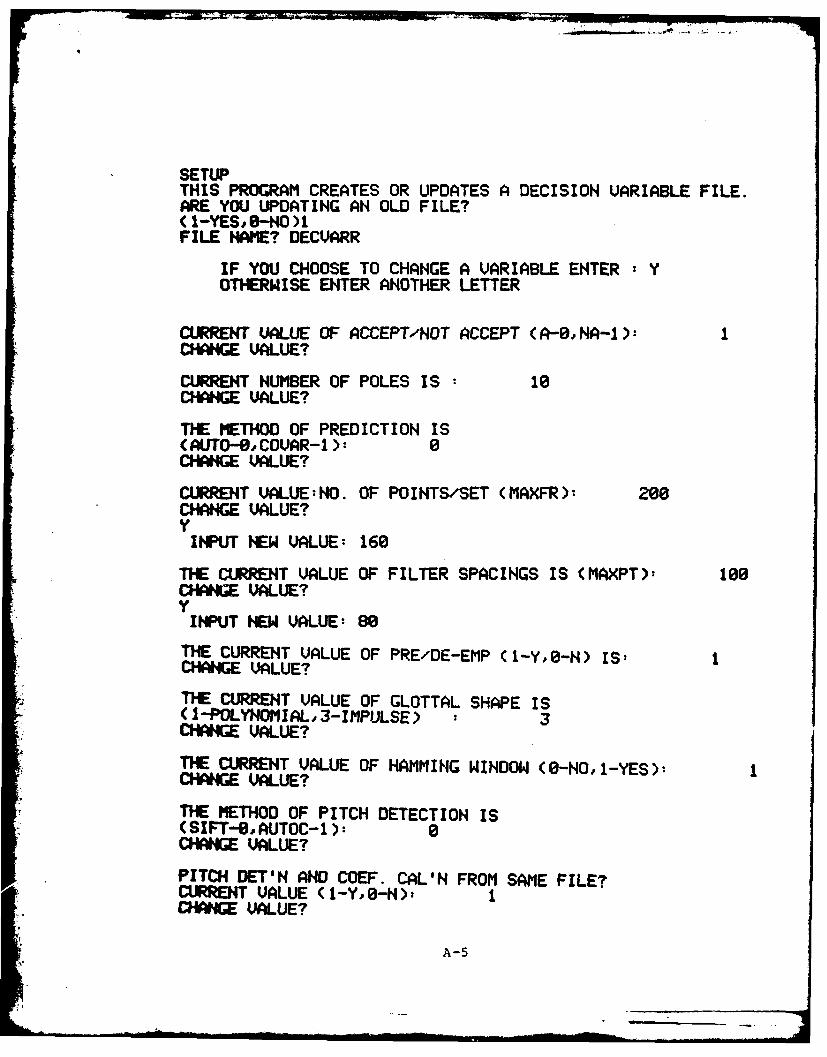
SETUPTHIS PROGRAM CREATES OR UPDATES A DECISION VARIABLE FILE.ARE YOU UPDATING AN OLD FILE?(1-YES -NO )1FILE NAME? DECVARR
IF YOU CHOOSE TO CHANGE A VARIABLE ENTER : YOTHERWISE ENTER ANOTHER LETTER
CURRENT VALUE OF ACCEPT/NOT ACCEPT (A--,NA-I):CHAWGE VALUE?
CURRENT NUMBER OF POLES IS 10CHANGE VALUE?
THE METHOD OF PREDICTION IS(AUTO-@, COUAR-1 0CHANGE VALUE?
CURRENT UALUE:NO. OF POINTS/SET (MAXFR): 200CHANGE VALUE?
INPUT NEW VALUE: 160
THE CURRENT VALUE OF FILTER SPACINGS IS (MAXPT)- 100CHANGE VALUE?
INPUT NEW VALUE: 80
THE CURRENT VALUE OF PRE/DE-EMP (1-YO-N) IS:CHANGE VALUE?
TIE CURRENT VALUE OF GLOTTAL SHAPE IS(1-POLYNOMIAL.3-IMPULSE) : 3CHANGE VALUE?
THE CURRENT VALUE OF HAMMING WINDOW (0-HO, 1-YES):CHANGE VALUE?
THE METHOD OF PITCH DETECTION IS(SIFT--, AUTOC-1): 0CHANGE VALUE?
PITCH DET'N AND COEF. CAL'N FROM SAME FILE?CURRENT VALUE (1-Y,O-N)t ICHARNGE VALUE?
A-5
U I .
THE CURRENT VALUE OF VOICED/UN THRESH IS: .400000CHANGE VALUE?Y
INPUT HEW REAL VALUE: .35
CLRRENT VALUE OF SPEECH SCALE-( IN CODER), 1.00000CHANGE VALUE?
CURRENT VALUE OF SILENCE THRESH-(IN ENER)IS, 350.000CHANGE VALUE?
CURRENT VALUE OF UNVOICED GAIN FACTOR IS, .100000CHANGE VALUE?
THE ARRAYS HAVE BEEN LOADEDDO YOU WANT TO HAVE THE ARRAY TYPED( -YES,0-HO): 1ACCEPT/NOT ACCEPT: 1NUMBER OF POLES: 10METHOD (8-AUTO,1-COVAR,): 0MAXFR' 160
PREDE-EIP (1-Y,O-N): 1GLOT (i-POLYHOMIAL,3-IMPULSE)- 3HAMMING WINDOW? (1-Y,0-N): 1METHOD PITCH DET (0-SIFT, 1-AUTOC): 0PITCH & COEF'S SAME FILE(1-Y,O-N): I
WRITE DECISION VARIABLES TO SAME FILE?(1-YES,-NO): 1PRINT ARRAY OH PRINTRONICS?(I-YO-H) 1PRORAM COMPLETED
STOPR
A-6
f ....
DECVARR
DATE 2/12/83
TIME 13:56:47
ACCEPT/NOT ACCEPT 1
NUMBER OF POLES 10
METHOD (0-AUTO, 1-COVAR) 0
MAXFR 160
MAXPT 80
PRE/DE-EMP? (1-Y,O-N) 1
GLOTTAL PULSE (1-POLY ,3-IMPULSE) 3
HAMMING WINDOW? (1-Y,O-N) 1
METHOD PITCH DET (0-SIFT, 1-AUTOC) 0
PITCH & COEF's F'M SAME FILE(1-Y,O-N) 1
VOICED/UNVOICED THRESHOLD .35000
SPEECH SCALE 1.00000
SILENCE THRESHOLD 350.00000
UNVOICED GAIN FACTOR .10000
A-7
PROGRAM PREDICT
FILE: PREDICT. FRDIRECTORY: DP4:KOWNLANGUAGE: FORTRAN5DATE: SEP 83AUTHOR: CRAIG MCKOWNSUBJECT: DIGITAL PROCESSING OF SPEECH--LINEAR PREDICTION ANALYZER
ARGUMENTS TYPE PURPOSE& VARIABLES
MAXPT INTEGER SAMPLES BETWEEN PITCH DETECTIONMAXFR INTEGER SAMPLES IN ANALYSIS WINDOWNSET INTEGER COUNTER FOR PITCH FRAME NUMBERNFRAME INTEGER COUNTER FOR LPC FRAME NUMBERNPTS INTEGER NUMBER OF SAMPLE POINTS ANALYZEDK,S,KS,JS,JK INTEGERS COUNTERS (USED FOR BOOKKEEPING)P1 INTEGER COUNTER FOR NUMBER OF SAMPLES TO
START OF NEXT LPC ANALYSIS WINDOWJUMP INTEGER FLAG INDICATING NATURE OF PREVIOUS
FRAME OF SPEECH (VOICEDUNVOICED ORSILENCE)
SPEEFL1 STRING NAME OF SPEECH FILE (FOR LPC)SPEEFL2 STRING NAME OF SPEECH FILE (FOR PITCH)DUMMY STRING NAME OF FILE HOLDING DECISION VARIABLESPARAM STRING NAME OF FILE TO WHICH LPC DATA IS
WRITTEN (ACTS AS TRANSMISSION CHANNEL)DECISION VARIABLES
POLES INTEGER NUMBER OF POLES IN THE OUTPUT FILTERMP INTEGER METHOD OF PREDICTION
(1-POLYNOM',2-TRIGON',3-IMPULSE)MPCH INTEGER METHOD OF PITCH DETECTION
(0-SIFT, 1-AUTOC)NPCS INTEGER PITCH/LPC FILES THE SAME (0-NO, I-YES)NEMP INTEGER PRE/DE-EMPHASIS (0-NO, I-YES)HI INTEGER HAMMING WINDOW (0-NO, 1-YES)STHR REAL VOICED/UNVOICED THRESHOLD
(USED FOR PITCH DETECTION)SCAF REAL SCALE FACTOR (INPUT SPEECH DIVIDED BY
THIS TO AVOID OVERFLOW)THRESH REAL SPEECH/SILENCE THRESHOLDUNGA REAL UNVOICED GAIN FACTOR (OUTPUT; UNVOICED
INPUT TO OUTPUT FILTER MULTIPLIED BYTHIS TO PREV
A-8
VARIABLES (CONT.)
VAL INT ARRAY DUMMY ARRAY TO HOLD THE SAMPLED SPEECHBEFORE IT IS WRITTEN TO SPEE & SPCH
SPEE REAL ARRAY ARRAY HOLDING DATA FOR LPC COEFFICIENTGENERATION
SPCH REAL ARRAY ARRAY HOLDING DATA FOR PITCH DETECTIONAR REAL ARRAY ARRAY HOLDING THE LPC COEFFICIENTS
AR(l)=AOAR(2)=Al... AR(POLES)=AP.ONLY AR(2) TO AR(POLES) ARE WRITTEN TOTHE CHANNEL FILE
RCOF REAL ARRAY REFLECTION COEFFICIENTSAENRG REAL ARRAY ENERGY FROM ENERGY DETECTORPITCH REAL ARRAY PITCH FROM PITCH DETECTORPIT INTEGER INTERPOLATED PITCH (WRITTEN TO CHANNEL)VOCD INTEGER FLAG INDICATING NATURE OF SPEECH
(WRITTEN TO CHANNEL)AL REAL ALPHA, ERROR COEFFICIENT, USED AS GAIN
FOR OUTPUT CHANNEL. COMPUTED IN COEF-FICIENT GENERATING ROUTINES.
FUNCTION:THIS PROGRAM EMULATES THE ANALYSIS OF A LINEAR PREDICTIVECODING SCHEME. IT INPUTS SAMPLED SPEECH DATA AND PRODUCESTHE PARAMETERS REQUIRED BY A VOCODER TO REPRODUCE THE SPEECH.THESE PARAMETERS ARE WRITTEN TO A FILE WHICH ACTS AS THECOMMUNICATION CHANNEL. FOR MORE INFORMATION, SEE MCKOWNTHESIS.THE FORM OF THE CHANNEL FILE IS COMPATIBLE TO THE VOCODERPROGRAM BY THE SAME AUTHOR.
PROGRAM USE:THE PROGRAM IS LOADED WITH THE FOLLOWING COMMAND:
RLDR PREDICT IOF SIFTB ENER DCOVAR DIRECT DAUTO AUTOC 2FLIB@
BEFORE RUNNING THIS PROGRAM, IT IS ADVISED THAT THE USERCREATE (OR UPDATE) A FILE CONTAINING THE DECISION VARIABLESREQUIRED TO PROPERLY EXECUTE THIS PROGRAM. THIS IS EASILYACCOMPLISHED BY USING THE PROGRAM "SETUP." SEE USER'S MANUALFOR THE PROGRAM "SETUP."I RECOMMEND THAT A MACRO FILE IS EMPLOYED TO RUN THISPROGRAM AND THE VOCODER PROGRAM USED TO SYNTHESIZE THESPEECH. THE MACRO FILE SHOULD BE OF THE FORM:
THE FILE SPEECHFILEI IS THE NAME OF THE INPUT SPEECH FILEUSED FOR THE PREDICTOR COEFFICIENT GENERATION. THE FILESPEECHFILE2 IS THE NAME OF THE INPUT SPEECH FILE USED TOACCOMPLISH THE PITCH DETECTION. THE FILE DECVAR IS THE NAME
A-9
OF THE FILE WHICH CONTAINS THE DECISION VARIABLES.THE NAME CHANNELFILE IS THE NAME OF THE FILE TO WHICH THELPC PARAMETERS ARE WRITTEN. IT MUST HAVE THE SAME NAMEAS THAT WHICH IS USED FOR VOCODE.
SUBROUTINES REQUIRED:NAME: LOCATION: PURPOSE:IOF DP4:KOWN READS RUN MACRO FILESIFTB A" PITCH DETECTIONAUTOC '' PITCH DETECTIONENER "' ENERGY DETECTIONDAUTO '' LPC COEF GENERATIONDCOVAR '' LPC COEF GENERATIONDIRECT '' DIRECT FORM FILTER
NOTE:SOME INFORMATION IS WRITTEN TO THE SCREEN TO ASSURE THEUSER THAT THE PROGRAM IS INDEED RUNNING. THE RUN TIMEOF THE PROGRAM IS ABOUT FOUR MINUTES, AND IS DEPENDENTUPON THE METHODS OF PITCH DETECTION AND COEFFICIENT GENER-ATION, AS WELL AS THE NUMBER OF POLES USED FOR ANALYSIS.
SEE USER'S MANUAL FOR "VOCODE"
A-1O
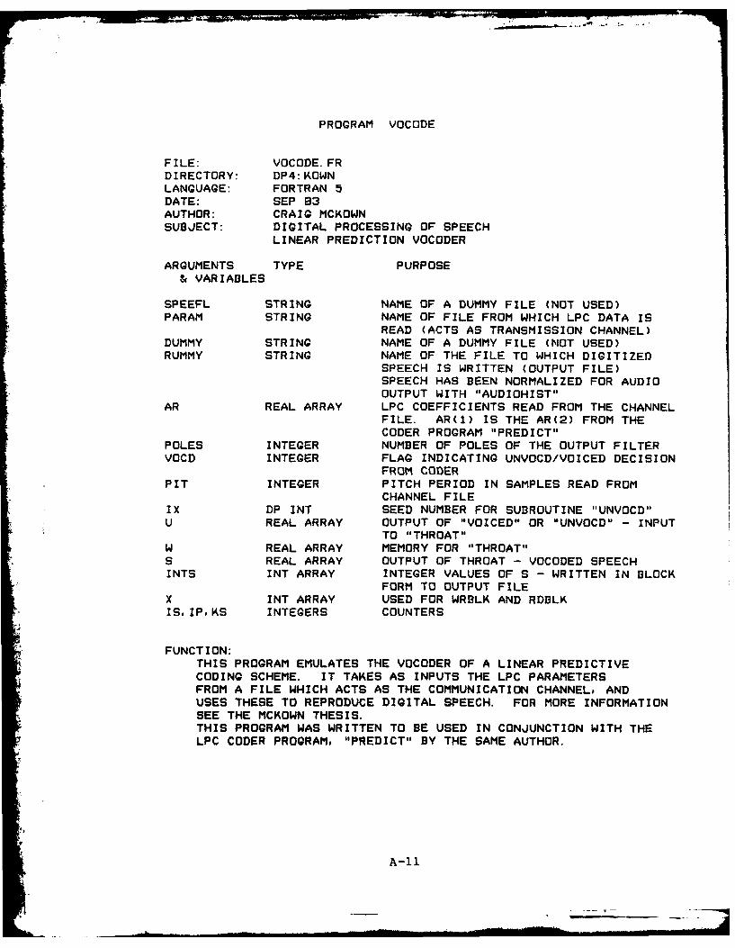
PROGRAM VOCODE
FILE: VOCODE. FRDIRECTORY: DP4:KOWNLANGUAGE: FORTRAN 5DATE: SEP 83AUTHOR: CRAIG MCKOWNSUBJECT: DIGITAL PROCESSING OF SPEECH
LINEAR PREDICTION VOCODER
ARGUMENTS TYPE PURPOSE& VARIABLES
SPEEFL STRING NAME OF A DUMMY FILE (NOT USED)PARAM STRING NAME OF FILE FROM WHICH LPC DATA IS
READ (ACTS AS TRANSMISSION CHANNEL)DUMMY STRING NAME OF A DUMMY FILE (NOT USED)RUMMY STRING NAME OF THE FILE TO WHICH DIGITIZED
SPEECH IS WRITTEN (OUTPUT FILE)
SPEECH HAS BEEN NORMALIZED FOR AUDIOOUTPUT WITH "AUDIOHIST"
AR REAL ARRAY LPC COEFFICIENTS READ FROM THE CHANNELFILE. AR(1) IS THE AR(2) FROM THECODER PROGRAM "PREDICT"
POLES INTEGER NUMBER OF POLES OF THE OUTPUT FILTERVOCD INTEGER FLAG INDICATING UNVOCD/VOICED DECISION
FROM CODERPIT INTEGER PITCH PERIOD IN SAMPLES READ FROM
CHANNEL FILEIX DP INT SEED NUMBER FOR SUBROUTINE "UNVOCD"U REAL ARRAY OUTPUT OF "VOICED" OR "UNVOCD" - INPUT
TO "THROAT"W REAL ARRAY MEMORY FOR "THROAT"S REAL ARRAY OUTPUT OF THROAT - VOCODED SPEECHINTS INT ARRAY INTEGER VALUES OF S - WRITTEN IN BLOCK
FORM TO OUTPUT FILEX INT ARRAY USED FOR WRBLK AND RDBLKIS, IPoKS INTEGERS COUNTERS
FUNCTION:THIS PROGRAM EMULATES THE VOCODER OF A LINEAR PREDICTIVECODING SCHEME. IT TAKES AS INPUTS THE LPC PARAMETERSFROM A FILE WHICH ACTS AS THE COMMUNICATION CHANNEL, ANDUSES THESE TO REPRODUCE DIGITAL SPEECH. FOR MORE INFORMATIONSEE THE MCKOWN THESIS.THIS PROGRAM WAS WRITTEN TO BE USED IN CONJUNCTION WITH THELPC CODER PROGRAM, "PREDICT" BY THE SAME AUTHOR.
A-II
I -- ;Rim
PROGRAM USE:THE PROGRAM IS LOADED BY THE FOLLOWING COMMAND:
THE PROGRAM "PREDICT" MUST BE EXECUTED BEFORE THIS PROGRAMCAN BE USED; THE OUTPUT OF THAT PROGRAM IS USED AS THEINPUT FOR THIS PROGRAM. IT IS RECOMMENDED THAT A MACROFILE BE USED TO RUN THIS PROGRAM. A SUGGESTED FORMAT IS:
THE FILE DUMMY IS THE NAME OF A DUMMY FILE. IT IS NOT USEDSO IT DOES NOT HAVE TO EXIST. THE FILE CHANNELFILE MUST BETHE SAME AS IS USED FOR THE PREDICT PROGRAM. THE NAMEOUTPUTSPEECH IS FOR THE FILE WHICH CONTAINS THE VOCODEDSPEECH.
THE OUTPUT FILE TO THIS PROGRAM CONTAINS A DIGITAL REPRE-SENTATION OF THE OUTPUT SPEECH. TO LISTEN TO THE SPEECH,THE PROGRAM "AUDIOHIST" MUST BE USED. THE OUTPUT FILE MUSTBE MOVED TO A DIRECTORY CONTAINING THIS PROGRAM (E.G.DPO:SPOUT). TO LISTEN TO THE OUTPUT SPEECH, GET INTO THEDIRECTORY WHICH NOW CONTAINS THE OUTPUT SPEECH FILE AND RUNTHE PROGRAM "AUDIOHIST." TO THE FIRST PROMPT TYPE THE NAMEOF THE OUTPUT SPEECH FILE, TO THE SECOND PROMPT TYPE "1",AND TO THE THIRD PROMPT TYPE "2."
SUBROUTINES REQUIRED:NAME: LOCATION: PURPOSE:IOF DP4:KOWN READS RUN MACRO FILEUNVOCD "o PRODUCES NORMAL RANDOM NOISE
WHICH DRIVES THE OUTPUT FILTERFOR UNVOICED SPEECH
DRAND of PRODUCES UNIFORMLY DISTRIBUTEDNOISE WHICH IS REQUIRED BY"UNVOCD"
VOICED# PRODUCES A GLOTTAL PULSE FORVOICED SPEECH
ACTUAL FILE NAMES ARE:GLOTI op GLOTTAL PULSE SHAPE: POLYNOM.GLOT2 " GLOTTAL PULSE SHAPE: TRIGONOM.GLOT3 '' GLOTTAL PULSE SHAPE: IMPULSE
THROAT THE OUTPUT FILTER
NOTE: THE INPUT FILE TO THIS PROGRAM SHOULD BE IN A FORM COMPATIBLEWITH THE CODER PROGRAM "PREDICT" WRITTEN BY C. MCKOWN. ANYOTHER FORM WILL GIVE SPURIOUS RESULTS.
A-12
TYPE RUNI.MCPREDICT DP5:FIVE/C OPS:FIVE/P DECUARR/I SYNLPC/OVOCODE S4/X LOUT/Y SYHLPC/I WORD:YO1/OR
46 TYPE POLES," POLESNPOLES = POLES + 1MAXFR1 = MAXFR - I ;FOR HAMMING WINDOWWRITE BINARY(3) POLESNEMP,UNGANGLT CHANNEL WRITE
C*** THE OPERATIONAL PROGRAM...
C*** START OF LOOP50 CONTINUE
CvI** READ IN A NEW BLOCK OF DATACALL RDBLK(loK,VALo5,IER) ; READ THE SPEECH INTO AN ARRAYIF (IER. EQ. 9) GO TO 260IF (IER. NE. 1) TYPE "READ FILE ERROR ", IER
C*** START A NEW FRAME OF PITCH DETECTION52 NSET = NSET + 1
NPOINT = 0F = S + MAXFR - IIF(NPCS. EQ.O) GO TO 60DO 55 J=S,F
NPOINT=NPOINT+ISPCH(NPOINT) = FLOAT(VAL(J))/SCAF ; SPCH FOR SIFT & ENER
55 CONTINUEGO TO 61
C*** USED IF PITCH AND COEFFICIENT FILES ARE DIFFERENT60 CALL RDBLK(4,KNAL,5oIER) ; READ THE SPEECH INTO AN ARRAY
IF (IER. EQ. 9) GO TO 260IF (IER.NE.1) TYPE "READ FILE ERROR ", IERDO 61 J=S,F
NPOINT=NPOINT+ISPCH(NPOINT) = FLOAT(NAL(J))/SCAF ; SPCH FOR SIFT & ENER
61 CONTINUE
C*** CALCULATE ENERGY IN A FRAME62 CALL ENER(SPCH, THRESH, NEN, AENRGMAXFR)
IF (NEN. EQ.O) GO TO 65 . NO NEED TO GET PITCH
C*** CALL TO THE SUBROUTINES WHICH PERFORM PITCH ANALYSIS63 IF(MPCH. EQ.O) CALL SIFTA(SPCHPITCHSTHR,MAXFR)
C*** LOAD ARRAY AND PREEMPHASIZE FOR COEFFICIENT GENERATIONIF(H1. EQ.0) GO TO 179 ; NO NEED FOR HAMMING WINDOWIF(NEMP. EQ.O) GO TO 81 ; NO PRE-EMPHASISDO 80 J = KSF
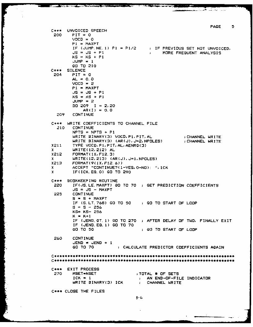
X211 TYPE VOCD,P1,PITAL, AENRG(3)X WRITE(12,212) ALX212 FORMAT(IX, F12.3)X WRITE(12,213) (AR(J),J=loNPOLES)X213 FORMAT(9(1X,F12.6))X ACCEPT "CONTINUE?(1-YES, 0-NO): ",ICKX IF(ICK. EQ.0) GO TO 290
C*** BOOKKEEPING ROUTINE220 IF(JS.LE.MAXPT) GO TO 70 GET PREDICTION COEFFICIENTS
JS = JS - MAXPT225 CONTINUE
S = S + MAXPT
IF (S. LT. 768) GO TO 50 gO TO START OF LOOPS = S - 258KS= KS- 256K - K+IIF (JEND.GT. 1) GO TO 270 ; AFTER DELAY OF TWO, FINALLY EXITIF (JEND. EQ. 1) GO TO 70GO TO 50 ; GO TO START OF LOOP
260 CONTINUEJEND = JEND + 1GO TO 70 ; CALCULATE PREDICTOR COEFFICIENTS AGAIN
C ADAPTED FROM SUBROUTINE WRITTEN BY LT. SIMMONS 10 SEPT 81CC THIS FORTRAN 5 SUBROUTINE WILL READ FROM THE FILE COM.CMC (FCOM.CM IN THE FORE GROUND) THE PROGRAM NAME,ANY GLOBALC SWITCHES, AND UP TO FOUR LOCAL FILE NAMES AND CORRESPONDINGC LOCAL SWITCHES.CC ARGUMENTS:CC N IS THE NUMBER OF LOCAL FILES AND SWITCHES TO BE READ FROMC (F)COM.CM. N MUST BE 1, 2, 3, OR 4.CC MAIN IS AN ASCII ARRAY FOR THE MAIN PROGRAM FILE NAME.CC Fl, F2, F3, AND F4 ARE THE FOUR ASCII ARRAYS TO RETURN THEC LOCAL FILE NAMES.CC MS IS A TWO-WORD INTEGER ARRAY THAT HOLDS ANY GLOBAL SWITCHESCC 51, S2, S3, AND S4 ARE TWO-WORD INTEGER ARRAYS THAT HOLD THEC LOCAL SWITCHES CORRESPONDING TO Fl THROUGH F4 RESPECTIVELY.C
C CHECK BOUNDS ON NIF(CN.LT.l).OR.(N.GT.4)) STOP ;N OUT OF BOUNDS
C PROCESS THE DATA IN (F)COM. CMCALL GROUND(I) ;FIND OUT WHICH GROUND PROGRAM IS INIF(I.EQ.0)OPEN 01 "COM. CM" ;OPEN CH. 0 TO COM.CMIF(I.EG.1)OPEN O."FCOM.CM" ;OPEN CH. 0 TO FCOM.CMCALL COMARG(OMAINMSIER) ;READ FROM (F)COM.CMIF( IER. NE. 1) TYPE" COMARG ERROR: ", IERWRITE(1O,1) MAIN(1) ;TYPE PROGRAM NAME
1 FORMAT(' PROGRAM ',S13. 'RUNNING.)CALL COMARGCO,Fl,Sl,JER) ;READ FROM (F)COM.CMIF(JER.NE.1) TYPE" COMARG ERROR (Fl):",JE-RIF(N.EQ.1) GO TO 2 ;TEST NCALL COMARG(0,F2,S2,KER) ;READ FROM (F)COM.CMIF(KER.NE.1) TYPE" COMARG ERROR (F2):",KERIF(N. EQ.2) GO TO 2 ;TEST NCALL COMARG(0.F3,S3,LER) ;READ FROM (F)COM.CMIF(LER.NE.1) TYPE" COMARG ERROR (F3):",LERIF(N. EQ.3) GO TO 2 ;TEST NCALL COMARG(0,F4,S4,LER) ;READ FROM (F)COM.CMIFCLER.NE.l) TYPE" COMARO ERROR (F4):".LER
CC THIS SUBROUTINE DETERMINES WHETHER A FRAMES ENERGYC EXCEEDS A SILENCE THRESHOLD (NEN=O:SILENCE; NEN=I:SPEECH)CC AENRG IS A THREE-MEMBER ARRAY WHICH HOLDS A MEMORY OF THEC PREVIOUS VALUES OF THE COMPUTED ENERGY.CC******************************************************************
CC SIFT ALGORITHM PROCESSING - STEP1CC INPUT PARAMETERS: SPCH(J) (J=1,2,. .. ,MAXFR)C THE SPEECH SIGNAL TO BE PROCESSED FOR PITCHCC OUTPUT PARAMETER: PITCH(J) (J=1.2,3)C (UNITS IN SAMPLES)CC NOTE: PARAMETERS FIXED FOR FS=8 KHZC
C************************************************************CC THIS SUBROUTINE CALCULATES THE PITCH PERIODCC INPUT PARAMETERS: SPCH(J) J=12, ... ,MAXFRC THE SPEECH SIGNAL TO BE PROCESSED FOR PITCHCC OUTPUT PARAMETERS: PITCH(J) J=1,2,3C THE PITCH IN NUMBER OF SAMPLESCC NOTE: PARAMETERS SET FOR FS - 8KHZCC***************************************************************
CC SUBROUTINE AUTO AS PRESENTED ON PAGE 219 OF MARKEL & GRAYCC THE ARITHMETIC IN THIS SUBROUTINE IS PERFORMED IN DOUBLEC PRECISION TO REDUCE THE EFFECTS OF ILL-CONDITIONING OF THEC AUTOCORRELATION MATRIX.C
11A38 0 IMPLEMENTING LPC ( NEAR PREDICTIVE CODING) ALGORITHMS 22IN THESTUDY OF SP..U AIR FORCE ND OF TECHWRIGHT-PATTERSON AFB ON SCHOOL OF ERGI. C E MCKOWN
CC SUBROUTINE COVAR AS PRESENTED ON PG 221 OF MARKEL & GRAYCC THE NUMERICAL MANIPULATIONS REQUIRED IN THIS ALGORITHM AREC PERFORMED IN DOUBLE PRECISION ARITHMETIC TO COMBAT POSSIBLEC ILL-CONDITIONING OF THE COVARIANCE MATRIX.C
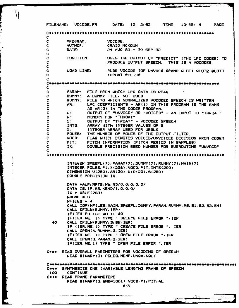
C PROGRAM: VOCODE.C AUTHOR: CRAIG MCKOWNC DATE: 24 AUG 83 - 30 SEP 83CC FUNCTION: USES THE OUTPUT OF "PREDICT" (THE LPC CODER) TOC PRODUCE OUTPUT SPEECH. THIS IS A VOCODER.CC LOAD LINE: RLDR VOCODE IOF UNVOCD DRAND GLOT1 GLOT2 GLOT3C THROAT @FLIBe
C
C
C PARAM: FILE FROM WHI'CH LPC DATA IS READC DUMMY: A DUMMY FILE, NOT USEDC RUMMY: FILE TO WHICH NORMALIZED VOCODED SPEECH IS WRITTENC AR: LPC COEFFICIENTS - AR(1) IN THIS PROGRAM IS THE SAMEC AS AR(2) IN THE CODER PROGRAM.C U: OUTPUT OF "UNVOCD" OR "VOICED" - AN INPUT TO "THROAT"C W: MEMORY FOR "THROAT"C S: OUTPUT OF "THROAT" - VOCODED SPEECHC INTS: ARRAY WITH INTEGER VALUES OF SC X: INTEGER ARRAY USED FOR WRBLKC POLES: THE NUMBER OF POLES OF THE OUTPUT FILTER.C VOCD: FLAG WHICH DENOTES VOICED/UNVOICED DECISION FROM CODERC PIT: PITCH INFORMATION (PITCH PERIOD IN SAMPLES)C IX: DOUBLE PRECISION SEED NUMBER FOR SUBROUTINE "UNVOCD"C
INTEGER SPEEFL(7),PARAM(7),DUMMY(7)oRUMMY(7)oMAIN(7)INTEGER POLES,P1oX(256),VOCDoPITINTS(200)DIMENSION U(250)oAR(20),W(0:20)oS(250)DOUBLE PRECISION IX
DATA VALF, NPTS°N6,N5/0.0,000/DATA IS, IP.KS.KEND/1,0,00/IX - DBLE(203)
NDONE - 0NFILES - 4CALL IOF(NFILES, MAIN SPEEFL, DUMMY, PARAM, RUMMY, MS, S1, S2, S3, S4)CALL DFILW(RUMMYoIER)IF(IER.EG. 13) GO TO 40IF(IER.NE. 1) TYPE " DELETE FILE ERROR "PIER
40 CALL CFILW(RUMMY,3o8#IER)IF (IER.NE.1) TYPE " CREATE FILE ERROR ", IERCALL OPEN(4, RUMMY, 3.IER)IF(IER.NE. 1) TYPE " OPEN FILE ERROR "PIERCALL OPEN(3,PARAM,3, IER)IF(IER. NE. 1) TYPE " OPEN FILE ERROR "PIER
C*** READ OVERALL PAREMETERS FOR VOCODING OF SPEECHREAD BINARY(3) POLES, NEMP°UNGA, NGLT
C********************************************************************-C*** SYNTHESIZE ONE EVARIABLE LENGTH3 FRAME OF SPEECH
100 CONTINUEC*** READ FRAME PARAMETERS
READ BINARY(3,END-1001) VOCD.P1,PITAL0 -21
PAGE 2DO 110 J-1,POLES
READ DINARY(3,END=1001) AR(J)110 CONTINUE
C*** SET MEMORY OF OUTPUT FILTER TO ZERODO 120 1 0,20
W(I) =0. 0120 CONTINUE
C*** VOCD/UNVOCD/SILENCE DECISIONVIF(VOCD.EQ.l) GO TO 300 ;VOICED SPEECHIF(VOCD. EQ. 2) 0O TO 400 ;SILENCE
C*** UNVOICED SPEECHCALL UNVOCD(U.Pi. IX)AL - AL*UNGA £UNVOICED GAIN FACTORCALL THROAT(U, P1.AR. POLES, AL, S. )GO TO 500
VALD - S(J)IF(VALD. OT. 2000.) VALD u2000.IF(VALD. LT. -2000.) VALD -- 2000.VALE - VALD + .9*VALF iY(Z) - X(Z) + .9(Z**-l)Y(Z)VALF - VALEINTS(J) - INT(VALE)
550 CONTINUEGO TO 560
C*** NO DE-EMPHASIS555 CONTINUE
DO 560 Jin*lINTS(J) - INT(9(J))
560 CONTINUE
C*** COUNTER & WRITE ROUTINEIP -IP + P1LIF(IP. GE. 256) GO TO 210 ;SPLIT S(1) & WRBLK(... 4. ...)DO 200 1 - IS. IP
X(I) - INTS(L) ;LOAD UP X(I) AS REQUIREDL -L+ 1
200 CONTINUEGO TO 240 ;SKIP WRDLK
210 CONTINUE
PAGE 3
IP = IP - 256 ;RESET IP
DO 220 I - IS, 256X(I) = INTS(L) ;LOAD UP X(I)L=L+ I
220 CONTINUECALL WRBLK(4, KS, X, 1.IER)IF (IER. EG. 9) GO TO 1001 ;END OF FILEIF(IER.NE.1) TYPE " WRBLK ERROR ON FILE #2 ",IERIF(IP. EQ.0) GO TO 230DO 230 I - 1,IP
X(I) - INTS(L) ;RESTART LOAD UP OF X(I)L-L+ I
230 CONTINUEKS - KS + 1 ;INCREMENT BLOCK COUNT
240 IS = IP+1NDONE = NDONE + 1GO TO 100
C*** SPEECH VOCODED1001 CONTINUE
TYPE " NDONE = ",NDONETYPE " SPEECH VOCODED
C*** NORMALIZATION ROUTINESi =0.0DO 700 J = 0,87
CALL RDBLK(4., XI., IER)IF(IER. EQ. 9) GO TO 701IF(IER.NE.1) TYPE " RDBLK ERROR ON FILE #2 ",IERDO 600 I = 1,256
N2 = IABS(X(I))S IF(N2.GT.NS) N5 = N2 CHECK FOR MAXIMUM VALUE
600 CONTINUEKEND = J
700 CONTINUE701 CONTINUE
TYPE" THE MAX VALUE FOUND WAS " ,N5S2 = 2000. 0/FLOAT(NS)DO 800 J - 0,KEND
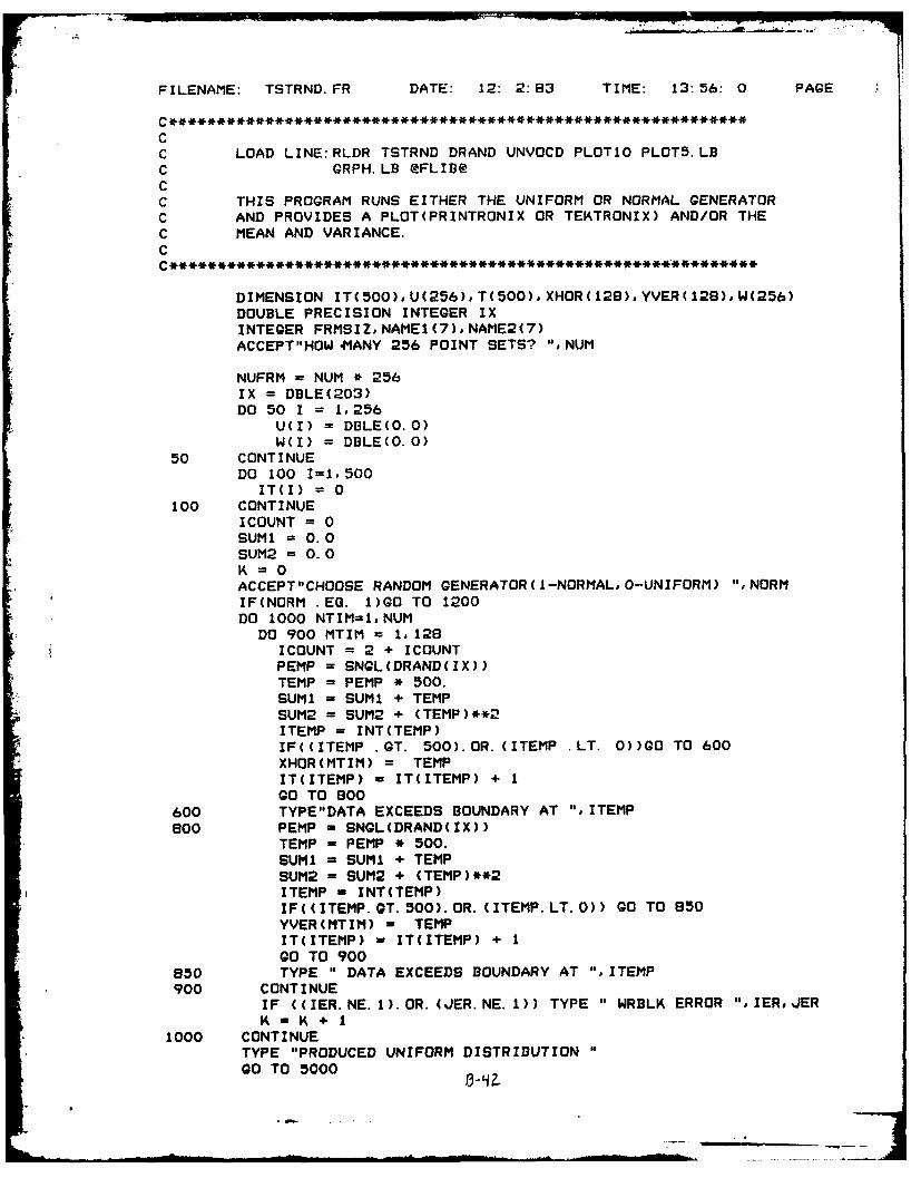
CC THIS SUBROUTINE CREATES A NORMAL RANDOM SEQUENCE WHICH WILLC BE A RANDOM NOISE INPUT TO THROAT. THE OUTPUT OF THISC PROGRAM IS AN ARRAY, U(I), OF LENGTH AS DETERMINED IN THEC CALLING ROUTINE.CC NOTE: THIS MUST BE LINKED TOGETHER WITH DRAND.CC PARAMETERS: U(I) : OUTPUT SEQUENCEC FRMSIZ : LENGTH OF ARRAYC IX : DOUBLE PRECISION SEED TO THIS ROUTINEC A NEW IX IS GENERATED BY THE PROGRAMC TO FEED THE NEXT ITERATION.C DRAND(IX): A DOUBLE PRECISION FUNCTION -C GENERATES UNIFORM PDF.CC **************** **** **** ****** ********************
c THIS SUB3ROUTINE PRODUCES AN INPUT TO THE SYNTHESIS FILTERCC GLOTTAL PULSE SHAPE -TRIGONOMETRIC
CCC
C
C NP NN
CC -'<-P-><-T->
C
C -'<------1 PITCH PERIOD ------------ >CC INPUTS:C PPF: THE PITCH PERIODC SIZE: THE FRAME SIZECC OUTPUTS:C U(I): THE OUTPUT SEQUENCE NEEDED AS INPUT TO "THROAT."C
SUBROUTINE VOICED2(U. PPF, SIZE)
DIMENSION U(200)
INTEGER PPF, SIZE
PI= 3. 14159P12 =PI/2.0
NPOS =1TP = .030 * FLOAT(PPF)TN = . 012 * FLOAT(PPF)NP = INT(TP)NN = INT(TP + TN)M -SIZE/PPF ;NUMBER OF PITCH PERIODS PER FRAMEK 0DO 60 J = 1,M
C*** CALCULATE ONE FRAME OF U(I)TIME = 1.0DO 50 1 = 1,PPF
K= K+ 1IF(I .GT. NP)GO TO 20U(K) - (.5)*(1.0-COB(TIME*PI/TP))GO TO 40
20 IF(I .GT. NN)QO TO 30U(K) - (.5)*CDS(((TIME-TP)/TN)*PI2)GO TO 40
C **********************************************************
CC THIS SUBROUTINE INPUTS U (A SEQUENCE OF VOICED/UNVOICEDC INPUTS) AND PASSES IT THROUGH A TIME VARYING DIGITAL FILTERC TO PRODUCE AN OUTPUT SPEECH SEQUENCE.CC INPUTS:C U(I): SEQUENCE GENERATED BY EITHER "VOICED" OR "UNVOCD."C EITHER A PULSE AT THE PITCH PERIOD OR RANDOM NOISE.C ICOUNT: THE FRAME LENGTHC FILTER: THE FILTER COEFFICIENTSC NORDER: THE ORDER OF THE FILTERC GAINI: THE GAIN OF THE FILTER, AL IN THE "VOCODE."C W(I): THE MEMORY OF THE FILTERCC OUTPUTS:C W(I): THE MEMORY OF THE FILTERC S(I): THE OUTPUT SPEECH SEQUENCEC
C*** NEW OR OLD FILE ***TYPE "THIS PROGRAM CREATES OR UPDATES A DECISION VARIABLE FILE."
TYPE "ARE YOU UPDATING AN OLD FILE?"ACCEPT"(1-YES, O-NO)",YES
C*** GET FILE NAME ***
20 ACCEPT"FILE NAME? "
READ(11,39)OUTFILE(1)39 FORMAT(S13)
IF (YES. EQ. 1)GO TO 30CALL DFILW(OUTFILE, JER)IF(JER.NE. 13) TYPE "YOU DELETED A CURRENT FILE!"IF((JER. NE. 1).AND. (JER. NE. 13)) TYPE "DELETE FILE ERROR",JERCALL CFILW(OUTFILEo2, JER)IF (JER.NE.1) TYPE "CREATE FILE ERROR!"oJER
C*** INITIALIZE THE ARRAYSNEW FILES-SET - TO O,OLD FILES-READ IN
C OLD FILES***IF (YES.EG.1)QO TO 50
DO 45 I-IoSIZER45 RELVAR(I) - 0.0
DO 47 I-I.SIZEI47 INTVAR(I) - 0
GOTO 6050 READ (1,901)(RELVAR(I),I-I,SIZER)
I i, ° i I i I I I I I - 35 ..
KPAGE 2READ (1,902)(INTVAR(I), I-1,SIZEI)
C*** UPDATE ARRAYS**60 CONTINUE
TYPE" (CR>X IF YOU CHOOSE TO CHANGE A VARIABLE ENTER Y V CR>X OTHERWISE ENTER ANOTHER LETTER (CR>
TYPE *
TYPE"CURRENT VALUE OF ACCEPT/NOT ACCEPT (A-0,NA-1): ".INTVAR(1)TYPE "CHANGE VALUE? "o
CALL RCHAR(ICHAR. lER)IF(ICHAR.NE.89)GO TO 5000
ACCEPT" (CR> INPUT NEW VALUE :"I.INTYAR (1)
I00 TETYPE"CURRENT NUMBER OF POLES IS :". INTVAR(2)TYPE"CHANGE VALUE? "
CALL RCHAR(ICHAR. IER)
IF(ICHAR. NE. 89)00 TO 5001
ACCEPT" (CR> INPUT NEW VALUE: ". INTVAR(2)
5001 TYPE so"TYPE"THE METHOD OF PREDICTION IS"TYPE"(AUTDO,COVAR-i): ". INTVAR(3)TYPE "CHANGE VALUE?"CALL RCHAR(ICHAR. IER)IF(ICHAR. NE. 89)00 TO 5002ACCEPT"<CR> INPUT NEW VALUE: ",INTVAR(3)
5002 TYPE " "1
TYPE"CURRENT VALUE:NO. OF POINTS/SET (MAXFR): ",INTVAR(4)TYPE"CHANGE VALUE? "
CALL RCHAR(ICHAR. IER)IF(ICHAR. NE. 89)00 TO 5003ACCEPT"CCR> INPUT NEW VALUE: ". INTVAR(4)
5003 TYPE 11"TYPE"THE CURRENT VALUE OF FILTER SPACINGS IS (MAXPT): ",INTYAR(5)TYPE"CHANGE VALUE? "t
CALL RCHAR(ICHARIER)IF(ICHAR. NE. 89)00 TO 5004ACCEPT"<CR> INPUT NEW VALUE: ". INTVAR(5)
5004 TYPE " "TYPE"THE CURRENT VALUE OF PRE/DE-EMP (1-Y#0-N) IS: ",INTVAR(6)TYPE"CHANGE VALUE? "s
CALL RCHAR(ICHARIER)IF(ICHAR. NE. 89)00 TO 5005ACCEPT"(CR> INPUT NEW VALUE: ", INTVAR(6)
5005 TYPE " "o
TYPE"THE CURRENT VALUE OF GLOTTAL SHAPE IS"TYPE"(1-POLYNOMIAL. 3-IMPULSE) :". INTVAR(7)TYPE"CHANGE VALUE?"CALL RCHAR(ICHARIER)IF(ICHAR. NE. 99)00 TO 5008ACCEPT"(CR> INPUT NEW VALUE: ". INTVAR(7)
5006 TYPE""
PAGE 3TYPE"THE CURRENT VALUE OF HAMMING WINDOW (0-NO.1-YES): ",INTVAR(B)TYPE' CHANGE VALUE? of
CALL RCHAR(ICHAR. IER)IF(ICHAR. NE. 89)00 TO 5007
* . ACCEPT"<CR> INPUT NEW VALUE: ', INTYAR(S)
5007 TYPE totTYPE'THE METHOD OF PITCH DETECTION ISTYPE"(SIFT-0,AUTOC-1): '$ INTVAR(9)TYPE"CHANGE VALUE? af
CALL RCHAR(ICHAR. IER)IF(ICHAR.NE.89)GO TO 5008ACCEPT"<CR> INPUT NEW VALUE: % INTVAR(9)
5008 TYPE to~TYPE"PITCH DET'N AND COEF. CAL'N FROM SAME FILE?"TYPE"CURRENT VALUE (1-Y, 0-N): ". INTVAR( 10)TYPE'CHANGE VALUE?CALL RCHAR(ICHAR, IER)IF(ICHAR. NE. 89)00 TO 5010ACCEPT"'ZCR> INPUT NEW VALUE: ",INTVAR(10)
5010 TYPE to toTYPE mt THE CURRENT VALUE OF VOICED/UN THRESH IS: 1,RELVAR(1)TYPE"CHANGE VALUE? asCALL RCHAR(ICHAR. IER)IF(ICHAR. NE. 89)00 TO 5011ACCEPT"<CR> INPUT NEW REAL VALUE: '%RELVAR(1)
5011 TYPE is aoTYPE"CURRENT VALUE OF SPEECH SCALE-(IN CODER): ",RELVAR(2)TYPE"CHANGE VALUE? it
CALL RCHAR(ICHAR, IER)IF(ICHAR.NE.89)GO TO 5015ACCEPT"(<CR> INPUT NEW REAL VALUE: ",RELVAR(2)
5015 TYPE to maTYPEaSCURRENT VALUE OF SILENCE THRESH-(IN ENER)IS: ".RELVAR(3)TYPE"aCHANGE VALUE? IsCALL RCHAR(ICHAR. IER)IF(ICHAR. NE. 89)00 TO 5016ACCEPT"'ZCR> INPUT NEW REAL VALUE: ".RELVAR(3)
5016 TYPE aa maTYPEaaCURRENT VALUE OF UNVOICED GAIN FACTOR IS: ",RELVAR(4)TYPEaCHANGE VALUE? tCALL RCHAR(ICHARIER)IF(ICHAR. NE. 99)00 TO 5020ACCEPT"<CR> INPUT NEW REAL VALUE: %,RELVAR(4)
5020 CONTINUE
C*** TYPE ARRAY *1
TYPENTHE ARRAYS HAVE BEEN LOADED"ACCEPT"DO YOU WANT TO HAVE THE ARRAY TYPED(1-YES. 0-NO): ",YESIF(YES EQ. 0)00 TO 200TYPE" ACCEPT/NOT ACCEPT: ",INTVAR(1)TYPE" NUMBER OF POLES: a ZNTVAR(2)TYPE" METHOD (0-AUTO, 1-COVAR9 ): "*INTVAR (3)TYPE" MAXFR: ma INTVAR(4)
200 TYPE "WRITE DECISION VARIABLES TO SAME FILE?"ACCEPT "(1-YES,0-NO): ".,YES2IF (YES2 .EQ. 1)GO TO 75CALL CLOSE(1.IER)IF (IER .NE. 1)TYPE"CLOSE FILE ERRORI ",IERACCEPT"FILE NAME?"READ( 11, 69)OUTFILE( 1)
69 FORMAT(S13)CALL DFILW(OUTFILE, JER)IF(JER.EQ. 13) TYPE "YOU DELETED A CURRENT FILE!"IF((JER. NE. 1). AND. (JER. NE. 13)) TYPE "DELETE FILE ERROR",JERCALL CFILW(OUTFILE, 2.JER)IF (JER.NE.1) TYPE "CREATE FILE ERROR!".JER
CC PROGRAM SCALE. FRCC THIS PROGRAM SCALES SPEECH FILES SO THAT THERE IS A MAX VALUEC OF 1900 AND CAN DE-EMPHASIZE SPEECHCC INPUT: MUST BE A BLOCKED FILEC
DIMENSION 91(256). U(256)DOUBLE PRECISION IXINTEGER OUTFILE(7). INFILE(7),FILUFD(IB),SPEECH(256)IX - DBLE(203)FLIP -1.0NNEWS -0ACCEPT"WARNING: THE INPUT FILE MUST BE AN INTEGER FILE <CR>
X AND BE IN BLOCKED FORM. (CR> (CR>X DO YOU WISH TO CONTINUE?(1-Y,0-N) ",NYZ
IF(NYZ .EQ. 0)G0 TO 60ACCEPT"INPUT FILENAME :
READ( 11.39) INFILE( 1)39 FORMAT(S13)
OPEN 1. INFILE.ATT-"CI".ERR=40FLIP = 1.0ACCEPT"OUTPUT FILENAME :
900 CONTINUEN15 = N6 * 256TYPE"THE FOLLOWING NO. OF POINTS WERE OUTPUT ",N15CALL CLOSE(1,IER)IF(IER .NE. 1)TYPE"CLOSE ERROR ON INPUT ", IERCALL CLOSE(2oIER)IF(IER NE. 1)TYPE"CLOSE ERROR ON OUTPUT ",IERTYPE"BLOCKS PROCESSED: ",N6GO TO 60
so CONTINUEx DAL = DAL - D1(I)*DK(I)*DAL200 CONTINUEX CALL OVERFL(IFLO)X IF(IFLO.EQ.l) TYPE " OVERFLOW IN LATTICEX IF(IFLO. EQ.3) TYPE " UNDERFLOW IN LATTICE
S. NAME OF PERFORMING ORGANIZATION b. OFFICE SYMBOL 7& NAME OF MONITORING ORGANIZATION
School of Engineering ArIT/E Y
6c. ADDRESS (City. State end ZIP CodIj 7b. ADORESS (City. State and ZIP Code)
Air Force Institute of Technology
'.!'right-Patterson AFB, 011 45433
go. NAME OF FUNDING/SPONSORING Eb. OFFICE SYMBOL 9. PROCUREMENT INSTRUMENT IDENTIFICATION NUMBERORGANIZATION (if applicable)
Bc. ADDRESS (City. State and ZIP Codal 10. SOURCE OF FUNDING NOS.
PROGRAM PROJECT TASK WORK UNITELEMENT NO. NO. NO. NO.
11. TITLE (Include Security Clasuufication)
See Box 19
12. PERSONAL AUTHOR(S)
Craig E. McKown, BSEE, 2LT, USA13& TYPE OF REPORT 13b. TIME COVERED 1.DATE OF REPORT s Yr. Mo.. Day) IS. PAGE COUNT
"S Thesis FROM TO 193 December16. SUPPLEMENTARY NOTATION
17. COSATI CODES IS. SUBJECT TERMS (Continua on rewrme it ,
FIELD GROUP SU OR. Linear Predictive Coding; Digital Speech Processing;.17 02
19. ABSTRACT (Continue on muvers if inecary and Identify by block numberl
Title: IM.LEMENTIN'G LPC ALGORITI'S IN THE STUDY OF SPEECH PROCESSING
Thesis Chairman: Larry Kizer, MNajor, USAF
20. OISTRISUTIONIAVAILABILITY OF ABSTRACT 21. ABSTRACT SECURITY CLASSIFICATION
UNCLASSIFIED/UNLIMITED Kj SAME AS RPT. 0 OTIC USERS [ UCLASSIFIED
122a. NAME OF RESPONSIBLE INDIVIDUAL 22b. TELEPHONE NUMBER 22c. OFFICE SYMBOL122 fliIetud A te Code)
[ Larry Kizer, !ajor, USAF (513)-255-3517 AFIT/E'Y
DO FORM 1473, 83 APR EDITION OF I JAN 73 IS OBSOLETE. UICLASSrTFDSECURITY CLASSIFICATION OF THIS PAGE
* . ,* .-*.-.-
SECURITY CLASSIFICATION OF THIS PAGE
This report describes a system which processes speech usinglinear predictive methods. The system is a software simulation ofan LPC analyzer and synthesizer. The system consists of two programs,one of which processes the speech to generate the LPC parameters,and another which processes these parameters to resynthesize thespeech. An important aspect of the system is that it enables the userto select from various pitch and coefficient analysis methods. Iialso allows the user to vary other parameters in order to simulate-other chan7es in the processing scheme.
To test the operation of the s.stci, a regAen of testin' -:as- erforieteL ''" var, in- the rnr.,
-Wichi t',e user has coi.trol. 7.:e z:ara. et,*:,. arc. dalc- t,-,e~iuvLriLU'lis iad eac'. .a - ~~:~-i ~~v-:e.?
5ystam -:erate( satisfactorily over all of the decision variahles.The flexibility ex;hibited by t]:e system in this te3ting indicatesthat the system can be a valuable tool for the study of linearpredictive coding of speech in the Signal Processing Laboratoryat the Air Force Institute of Technology.