16
Global Top Smart MCU Innovator, ABOV Semiconductor www.abovsemi.com A31L12x Series How to use Real-Time Clock and Calendar (RTCC) Application Note Version 1.00

Global Top Smart MCU Innovator, ABOV Semiconductor www.abovsemi.com
A31L12x Series How to use Real-Time Clock and
Calendar (RTCC)
Application Note
Version 1.00

Contents/ List of Figures/ List of Tables A31L12x Series: How to use RTCC
2
Contents
1 Introduction .................................................................................................................................... 3
2 Clock Source .................................................................................................................................. 4
3 Timer Digit Format.......................................................................................................................... 5
3.1 12/24-Hour System ............................................................................................................. 6
3.2 Timer Values ........................................................................................................................ 7
3.2.1 Day of Week ........................................................................................................... 7
3.2.2 Leap Year................................................................................................................ 7
4 RTCC General Functionality .......................................................................................................... 8
5 Alarm .............................................................................................................................................. 9
5.1 Configuring the Alarm .......................................................................................................... 9
6 Interrupt ........................................................................................................................................ 10
6.1 Interrupt Configuration ...................................................................................................... 10
7 Time Error Correction ................................................................................................................... 12
7.1 Time Error Correction Example 1 ...................................................................................... 13
7.1.1 Measuring the Oscillation Frequency ................................................................... 13
7.1.2 Calculating the Correction Value .......................................................................... 13
7.1.3 Calculating the Values to be Set to Register ........................................................ 13
7.2 Time Error Correction Example 2 ...................................................................................... 14
7.2.1 Measuring the Oscillation Frequency ................................................................... 14
7.2.2 Calculating the Correction Value .......................................................................... 14
7.2.3 Calculating the Values to be Set to Register ........................................................ 14
Revision History .................................................................................................................................... 15
List of Figures
Figure 1. RTCC Block Diagram ............................................................................................................... 3
Figure 2. Clock Selection Register and Clock Sources .......................................................................... 4
Figure 3. Timer Digit Format ................................................................................................................... 5
Figure 4. Display of 12/24-Hour Systems ............................................................................................... 6
Figure 5. Example of Updating RTCC Time and Date ............................................................................ 8
Figure 6. RTCC Initialization with Alarm Interrupt Enabled Code Example ............................................ 9
Figure 7. RTCC ISR Code Example (Alarm Interrupt) ............................................................................ 9
Figure 8. RTCC Initialization with Interval Interrupt Enabled Code and ISR Code Example................ 10
Figure 9. RTCC Time Error Correction Register ................................................................................... 12
List of Tables
Table 1. Day of Week Schedule .............................................................................................................. 7

A31L12x Series: How to use RTCC 1. Introduction
3
1 Introduction
This document describes the Real-Time Clock and Calendar (RTCC) hardware module, available on
A31L12x series, and its operation.
The RTCC module provides real-time clock and calendar. It is for the applications that must maintain
accurate time for extended periods of time with minimal or no intervention from CPU. In addition, the
RTCC module is optimized for low-power applications to provide extended battery life while keeping
track of time.
The RTCC consists of the clock source select circuit, second/minute/hour/day/week/month/year counter
circuits, alarm circuit, output select circuit, and error correction circuit. It is an independent BCD counter.
The RTCC circuitry and the related control bits are not reset by the system reset other than POR.
Some key features of the RTCC are listed below:
Calendar with 0.5 second accuracy in the format of year/ month/ week/ day/ hour/ minute/
second
Alarm function with interrupt
Time Error Correction function
Wake-up possible from Deep Sleep mode
Figure 1. RTCC Block Diagram

2. Clock Source A31L12x Series: How to use RTCC
4
2 Clock Source
Depending on the device, the RTCC module can be clocked with three different clock sources: external
real-time clock crystal (XSOSC) that is oscillating at 32.768kHz, internal Watchdog Timer RC OSC
(WDTRC) that is oscillating at 40kHz, and clock of the system clock (MCLK) which is divided by divider
2.
For devices with external and internal oscillators, the SCU_PPCLKSR<9:8> must be configured to
decide the clock source that the RTCC module uses for clocking: Setting these bits to ‘01’ selects the
external 32.768kHz crystal (XSOSC), while setting these bits to ‘10’ selects the internal 40kHz oscillator
(WDTRC). Setting these bits to ‘11’ selects the system clock (MCLK) which is divided by divider 2.
Setting these bits to ‘00’ sets the clock to low level.
Figure 2. Clock Selection Register and Clock Sources
A31L12x Series: How to use RTCC 3. Timer Digit Format
5
3 Timer Digit Format
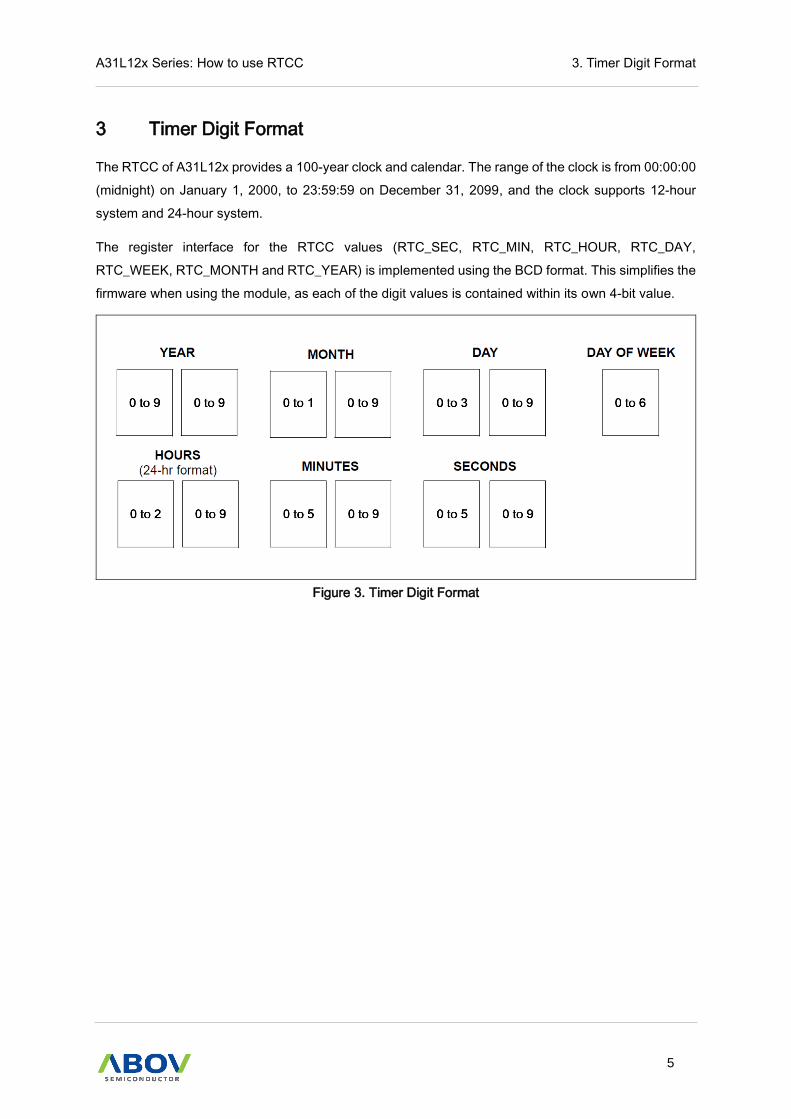
The RTCC of A31L12x provides a 100-year clock and calendar. The range of the clock is from 00:00:00
(midnight) on January 1, 2000, to 23:59:59 on December 31, 2099, and the clock supports 12-hour
system and 24-hour system.
The register interface for the RTCC values (RTC_SEC, RTC_MIN, RTC_HOUR, RTC_DAY,
RTC_WEEK, RTC_MONTH and RTC_YEAR) is implemented using the BCD format. This simplifies the
firmware when using the module, as each of the digit values is contained within its own 4-bit value.
Figure 3. Timer Digit Format

3. Timer Digit Format A31L12x Series: How to use RTCC
6
3.1 12/24-Hour System
The RTCC of A31L12x supports 12-hour system and 24-hour system. For devices with 12-hour system
and 24-hour system, the RTC_CR<10> must be configured to determine which system to use. Setting
the bit to ‘0’ selects the 12-hour system. Setting the bit to ‘1’ selects the 24-hour system.
If the 12-hour system is selected, the RTC_HOUR<5> indicates AM(0)/PM(1).
24-Hour Display 12-Hour Display
Time RTC_Hour Register Time RTC_Hour Register
0 00H 0 a.m. 12H
1 01H 1 a.m. 01H
2 02H 2 a.m. 02H
3 03H 3 a.m. 03H
4 04H 4 a.m. 04H
5 05H 5 a.m. 05H
6 06H 6 a.m. 06H
7 07H 7 a.m. 07H
8 08H 8 a.m. 08H
9 09H 9 a.m. 09H
10 10H 10 a.m. 10H
11 11H 11 a.m. 11H
12 12H 0 p.m. 32H
13 13H 1 p.m. 21H
14 14H 2 p.m. 22H
15 15H 3 p.m. 23H
16 16H 4 p.m. 24H
17 17H 5 p.m. 25H
18 18H 6 p.m. 26H
19 19H 7 p.m. 27H
20 20H 8 p.m. 28H
21 21H 9 p.m. 29H
22 22H 10 p.m. 30H
23 23H 11 p.m. 31H
Figure 4. Display of 12/24-Hour Systems

A31L12x Series: How to use RTCC 3. Timer Digit Format
7
3.2 Timer Values
3.2.1 Day of Week
The RTC_WEEK register indicates the count value of weekdays. It counts up in synchronization with
the RTCC day counter register.
Table 1. Day of Week Schedule
Day of Week
Sunday 0
Monday 1
Tuesday 2
Wednesday 3
Thursday 4
Friday 5
Saturday 6
3.2.2 Leap Year
The year range on the RTCC module is from 2000 to 2099; therefore, the leap year calculation is
determined by any year divisible by 4 in the above range. The only month to be affected in a leap year
is February, which has 29 days, but only 28 days in all other years.

4. RTCC General Functionality A31L12x Series: How to use RTCC
8
4 RTCC General Functionality
All timer registers having a time value of seconds or greater are writable. Users can configure the current
time by simply writing to these registers the desired year, month, day, hour, minutes and seconds. The
timer will then use the newly written values to proceed with the count from the desired starting point.
Figure 5. Example of Updating RTCC Time and Date
A31L12x Series: How to use RTCC 5. Alarm
9
5 Alarm
5.1 Configuring the Alarm
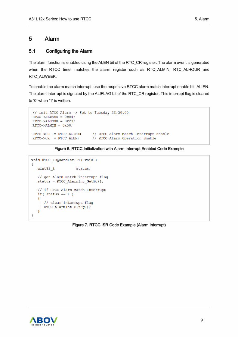
The alarm function is enabled using the ALEN bit of the RTC_CR register. The alarm event is generated
when the RTCC timer matches the alarm register such as RTC_ALMIN, RTC_ALHOUR and
RTC_ALWEEK.
To enable the alarm match interrupt, use the respective RTCC alarm match interrupt enable bit, ALIEN.
The alarm interrupt is signaled by the ALIFLAG bit of the RTC_CR register. This interrupt flag is cleared
to ‘0’ when ‘1’ is written.
Figure 6. RTCC Initialization with Alarm Interrupt Enabled Code Example
Figure 7. RTCC ISR Code Example (Alarm Interrupt)

6. Interrupt A31L12x Series: How to use RTCC
10
6 Interrupt
6.1 Interrupt Configuration
The RTCC module has one dedicated interrupt flag bit, RTIFLAG, and a corresponding interrupt interval
selection bit, RTIN. The RTIN is used to select the RTCC interrupt interval. There is one specific RTCC
interrupt vector.
The RTIFLAG bit is set when the time matches the RTCC interrupt interval value. The RTIFLAG bit is
cleared to ‘0’ when ‘1’ is written.
After an enabled interrupt is generated, the CPU will jump to the vector assigned to that interrupt. The
vector number for the interrupt is the same as the natural order number. The CPU will then begin
executing code at the vector address. The user’s code at this vector address should perform any
application specific operations and clear the RTIFLAG interrupt flag, and then exit.
Figure 8. RTCC Initialization with Interval Interrupt Enabled Code and ISR Code Example

A31L12x Series: How to use RTCC 6. Interrupt
11
Figure 8. RTCC Initialization with Interval Interrupt Enabled Code and ISR Code Example (continued)
7. Time Error Correction A31L12x Series: How to use RTCC
12
7 Time Error Correction
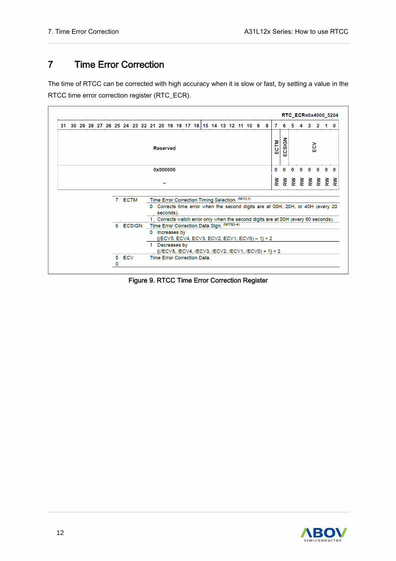
The time of RTCC can be corrected with high accuracy when it is slow or fast, by setting a value in the
RTCC time error correction register (RTC_ECR).
Figure 9. RTCC Time Error Correction Register

A31L12x Series: How to use RTCC 7. Time Error Correction
13
7.1 Time Error Correction Example 1
Example of correcting from 32772.3 Hz to 32768 Hz (32772.3 Hz – 131.2 ppm)
7.1.1 Measuring the Oscillation Frequency
The oscillation frequency of each product is measured by outputting about 32 kHz from the RTCOUT
pin or outputting about 1 Hz from the RTCOUT pin when the time error correction register is set to its
initial value (00H).
7.1.2 Calculating the Correction Value
If the target frequency is assumed to be 32768 Hz, the correction range for -131.2 ppm is -63.1 ppm or
less, so assume ECTM to be 0.
The expression for calculating the correction value when the ECTM is 0 is applied:
Correction value = Number of correction counts in 1 minute / 3
= (Oscillation frequency / Target frequency – 1) * 32768 * 60 / 3
= (32772.3 / 32768 – 1) * 32768 * 60 / 3 = 86
7.1.3 Calculating the Values to be Set to Register
If the correction value is 0 or more (when delaying), assume ECSIGN to be 0.
Calculate (ECV5, ECV4, ECV3, ECV2, ECV1, ECV0) from the correction value.
{(ECV5, ECV4, ECV3, ECV2, ECV1, ECV0) - 1} * 2 = 86
(ECV5, ECV4, ECV3, ECV2, ECV1, ECV0) = 44
(ECV5, ECV4, ECV3, ECV2, ECV1, ECV0) = (1, 0, 1, 1, 0, 0)
Consequently, when correcting from 32772.3 Hz to 32768 Hz, setting the correction register such that
ECTM is 0 and the correction value is 86 (RTC_ECR[6:0] = 0101100) results in 32768 Hz (0ppm).

7. Time Error Correction A31L12x Series: How to use RTCC
14
7.2 Time Error Correction Example 2
Example of correcting from 32767.4 Hz to 32768 Hz (32767.4 Hz + 18.3 ppm).
7.2.1 Measuring the Oscillation Frequency
The oscillation frequency of each product is measured by outputting about 32 kHz from the RTCOUT
pin or outputting about 1 Hz from the RTCOUT pin when the time error correction register is set to its
initial value (00H).
7.2.2 Calculating the Correction Value
Assume the target frequency to be 32768 Hz and ECTM to be 1.
The expression for calculating the correction value when ECTM is 1 is applied.
Correction value = Number of correction counts in 1 minute
= (Oscillation frequency / Target frequency – 1) * 32768 * 60
= (32767.4 / 32768 – 1) * 32768 * 60 = -36
7.2.3 Calculating the Values to be Set to Register
If the correction value is 0 or less (when quickening), assume ECSIGN to be 1.
Calculate (ECV5, ECV4, ECV3, ECV2, ECV1, ECV0) from the correction value.
- {(/ECV5, /ECV4, /ECV3, /ECV2, /ECV1, /ECV0) + 1} * 2 = -36
(/ECV5, /ECV4, /ECV3, /ECV2, /ECV1, /ECV0) = 17
(/ECV5, /ECV4, /ECV3, /ECV2, /ECV1, /ECV0) = (0, 1, 0, 0, 0, 1)
(ECV5, ECV4, ECV3, ECV2, ECV1, ECV0) = (1, 0, 1, 1, 1, 0)
Consequently, when correcting from 32767.4 Hz to 32768 Hz, setting the correction register such that
ECTM is 1 and the correction value is -36(RTC_ECR[6:0] = 1101110) results in 32768 Hz (0ppm).
A31L12x Series: How to use RTCC Revision History
15
Revision History
Version Date Description
1.00 21.03.08 Document created
Important Notice A31L12x Series: How to use RTCC
16
ABOV Disclaimer IMPORTANT NOTICE – PLEASE READ CAREFULLY ABOV Semiconductor ("ABOV") reserves the right to make changes, corrections, enhancements, modifications, and improvements to ABOV products and/or to this document at any time without notice. ABOV does not give warranties as to the accuracy or completeness of the information included herein. Purchasers should obtain the latest relevant information of ABOV products before placing orders. Purchasers are entirely responsible for the choice, selection, and use of ABOV products and ABOV assumes no liability for application assistance or the design of purchasers’ products. No license, express or implied, to any intellectual property rights is granted by ABOV herein. ABOV disclaims all express and implied warranties and shall not be responsible or liable for any injuries or damages related to use of ABOV products in such unauthorized applications. ABOV and the ABOV logo are trademarks of ABOV. All other product or service names are the property of their respective owners. Information in this document supersedes and replaces the information previously supplied in any former versions of this document.
© 2021 ABOV Semiconductor – All rights reserved
Korea
Regional Office, Seoul HQ, Ochang
R&D, Marketing & Sales R&D, QA, and Test Center
8th Fl., 330, Yeongdong-daero, Gangnam-gu, Seoul, 06177, Korea
93, Gangni 1-gil, Ochang-eup, Cheongwon-gun, Chungcheongbuk-do, 28126, Korea
Tel: +82-2-2193-2200 Fax: +82-2-508-6903 www.abovsemi.com
Tel: +82-43-219-5200 Fax: +82-43-217-3534 www.abovsemi.com
Domestic Sales Manager Global Sales Manager China Sales Manager Tel: +82-2-2193-2206 Fax: +82-2-508-6903 Email: [email protected]
Tel: +82-2-2193-2281 Fax: +82-2-508-6903 Email: [email protected]
Tel: +86-755-8287-2205 Fax: +86-755-8287-2204 Email: [email protected]


