Project Number A3743 Autonomous Robot With obstacle avoidance, drive wheel synchronization and line tracking capability Documentation Figure 1 - AUTONOMOUS ROBOT Project Features: • ATMega16 Microcontroller The ATMega16 monitors all robot sensors and controls motor drive functions. In system programming is available. Microcode was developed using the MCS Bascom AVR compiler. • Obstacle avoidance The robot maneuvers around obstacles while seeking for a black line to track. Obstacles cause direction reversal when the robot is in line tracking mode. The obstacle sensor is a Sharp GP2D15 sensor connected to INT0 of the ATMega16. • Line tracking The robot is designed to search for a black line on the terrain. Once the line is found, the robot tracks the line from end to end and reverses direction when it encounters an obstacle in the path of the line. Three infrared sensors mounted under the robot and connected to port D of the Mega16 do line sensing. • Differential Drive Two DC motors provide mechanical propulsion through friction drive of the drive wheels. The motors are electrically driven by two Allegro 3953 full bridge motor drivers connected to port Aof the ATMega16. • Drive Wheel Synchronization Infrared wheel encoders and a mi crocode routine provide wheel synchronizati on. This allows for straight-line travel withou t guidance. • Rechargeable Battery PackPower is provided by a rechargeable 9.6 Volt NiCad battery pack. There is a 5 Volt on-board regulator for logic power.
Project Number A3743 Autonomous RobotWith obstacle avoidance, drive wheel
synchronization and line trackingcapability
Documentation
Figure 1 - AUTONOMOUS ROBOT
Project Features:
• ATMega16 MicrocontrollerThe ATMega16 monitors all robot sensors andcontrols motor drive functions.
In system programming is available.Microcode was developed using the MCS Bascom AVR compiler.
• Obstacle avoidanceThe robot maneuvers around obstacles whileseeking for a black line to track.Obstacles cause direction reversal when the robot isin line tracking mode.The obstacle sensor is a Sharp GP2D15 sensorconnected to INT0 of the ATMega16.
• Line trackingThe robot is designed to search for a black line onthe terrain.Once the line is found, the robot tracks the linefrom end to end and reverses direction when itencounters an obstacle in the path of the line.Three infrared sensors mounted under the robotand connected to port D of the Mega16 do linesensing.
• Differential DriveTwo DC motors provide mechanical propulsionthrough friction drive of the drive wheels.The motors are electrically driven by two Allegro3953 full bridge motor drivers connected to port A of the ATMega16.
• Drive Wheel SynchronizationInfrared wheel encoders and a microcode routineprovide wheel synchronization. This allows forstraight-line travel without guidance.
• Rechargeable Battery Pack Power is provided by a rechargeable 9.6 Volt NiCadbattery pack.There is a 5 Volt on-board regulator for logic power.
2004 AVR DESIGN CONTESTPROJECT NUMBER A3743 / AUTONOMOUS ROBOT
BRIEF DESCRIPTION
This project is an autonomous robot that is capable of obstacle avoidance, drive wheelsynchronization and line tracking. The robot initializes in seek mode, where it avoids obstacles and
searches for a black line to track. Wheel synchronization, during seek mode, allows the robot totravel in a straight line without guidance. Once a black line is found, the robot tracks the line andreverses direction when an obstacle is encountered on the line.
The electronic control assembly consists of an Atmel ATMega16 MCU operating at 8Mhz withan internal clock. Two Allegro 3953 full-bridge motor drivers are used for motor control. Microcodefor the project was written using the MCS Basic-AVR compiler. Microcode can be updated using theon-board ISP connector.
The Mechanical assembly uses a differential drive system made from two small DC motors, afriction drive system and two 78mm wheels. There are six on-board sensors that allow the robot toavoid obstacles, synchronize wheel rotation and track lines. Power is provided by a rechargeable9.6V NiCad battery pack.
2004 AVR DESIGN CONTESTPROJECT NUMBER A3743 / AUTONOMOUS ROBOT
MECHANICAL DESCRIPTION
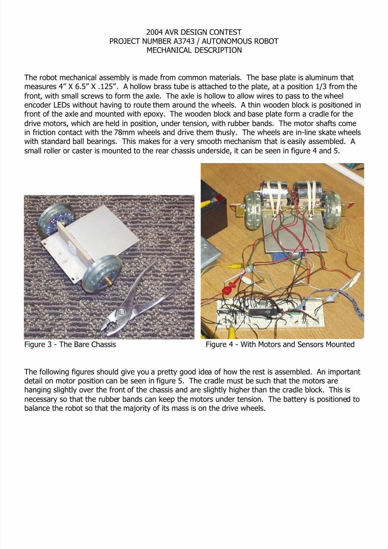
The robot mechanical assembly is made from common materials. The base plate is aluminum thatmeasures 4” X 6.5” X .125”. A hollow brass tube is attached to the plate, at a position 1/3 from the
front, with small screws to form the axle. The axle is hollow to allow wires to pass to the wheelencoder LEDs without having to route them around the wheels. A thin wooden block is positioned infront of the axle and mounted with epoxy. The wooden block and base plate form a cradle for thedrive motors, which are held in position, under tension, with rubber bands. The motor shafts comein friction contact with the 78mm wheels and drive them thusly. The wheels are in-line skate wheelswith standard ball bearings. This makes for a very smooth mechanism that is easily assembled. A small roller or caster is mounted to the rear chassis underside, it can be seen in figure 4 and 5.
Figure 3 - The Bare Chassis Figure 4 - With Motors and Sensors Mounted
The following figures should give you a pretty good idea of how the rest is assembled. An important
detail on motor position can be seen in figure 5. The cradle must be such that the motors arehanging slightly over the front of the chassis and are slightly higher than the cradle block. This isnecessary so that the rubber bands can keep the motors under tension. The battery is positioned tobalance the robot so that the majority of its mass is on the drive wheels.
$regfile = "m16def.dat"$crystal = 8000000 'We are using the 8Mhz internal clock
Dim Gp0 As Byte , Gp1 As Byte , Gp2 As Byte 'General Purpose registers
Dim Leftc As Integer , Rightc As Integer 'Wheel pulse countersDim Left_flag As Bit , Right_flag As Bit 'Wheel flip flop flagsDim Op_mode As String * 5 'Operating mode, i.e. seek or track
Motor Alias Porta 'Motor driver output portLsense Alias Pind.0 'Left line sensor ,0 = on lineRsense Alias Pind.1 'Right line sensor , 0 = on lineCsense Alias Pind.3 'Center line sensor, 0 = on lineOsense Alias Pind.2 'Obstacle sensor, 1 = obstacle senseLwheel Alias Pind.4 'Left wheel encoderRwheel Alias Pind.5 'Right wheel encoder
Config Int0 = Rising 'Obstacle sensor on INT0, Trigger on rising edgeConfig Pind.2 = Input 'Used as Int0 for obstacle sensorConfig Porta = Output 'Use port A for output'PA.0 = /enable PA.1 = Phase PA.2 = /Brake Right Motor'PA.4 = /enable PA.5 = Phase PA.6 = /Brake Left Motor'PD.0 = left line sensor PD.1 = right line sensor PD.2 = Center line sensor
On Int0 Int0_isr 'Point to the Interrupt 0 Service routineEnable Int0Enable InterruptsWait 3 'Delay after power on
Waitms 200 'Clear the cross-line areaGp1 = Pind And 3 'Gp1 = mask portd inputIf Gp1 = 3 Then Goto Reverse 'If left and right line sensors both see black Motor = Brake 'Turn on the brakeWait 1
Right_spin:Motor = Spinr 'Spin right to clear the main -lineWaitms 200
Right_spin_cont:
Motor = BrakeMotor = SpinrWaitms Pulse_width 'This pause adjusts the motor pulse widthIf Csense = 0 Then Goto Right_spin_cont 'Sp in until the center line sensor detects the lineMotor = Brake 'Turn on the brakeWait 1Return
'* * * * * * * * * * * * * * * * * * * * * * * * * * * * * * * *'Returns (Leftc) the left wheel encoder count and (Rightc) the Right wheel encoder count.Poll_wheels: 'Polls the wheel encoder sensors and counts pulses.
If Lwheel = 0 Then 'If left wheel encoder is uncoveredIf Left_flag = 1 Then 'Do this once each encoder sensor transition
Incr Leftc 'Increment the wheel counterReset Left_flagEnd If
End If If Lwheel = 1 Then Set Left_flag 'Set the flag when the sensor is covered
If Rwheel = 0 Then 'If right wheel encoder is uncoveredIf Right_flag = 1 Then 'Do this once each encoder sensor transition
Incr Rightc 'Increment the wheel counterReset Right_flag
End If End If
If Rwheel = 1 Then Set Right_flag 'Set the flag when the sensor is coveredReturn
'* * * * * * * * * * * * * * * * * * * * * * * * * * * * * * * *Int0_isr: 'Obstacle Sensor Interrupt 0 routine.Disable Int0 'No interrupt allowed during ISRWaitms 10 'Pause and re-check the obstacle sensorIf Osense = 0 Then Goto False_obs 'Eliminate false obstacle detectionIf Op_mode = "seek" Then 'Do this if there is an obstacle sensed in seek modeSeek_obs:
Motor = BrakeWaitms 300Motor = RevWaitms 300If Osense = 1 Then Goto Seek_obs 'Is the obstacle still there?Motor = BrakeWaitms 300Motor = Spinr 'Turn away from obstacleWaitms 500
End If
If Op_mode = "track" Then 'Do this if there is an obstacle sensed in track modeTrack_obs:
If Osense = 1 Then Goto Track_obs 'Is the obstacle still there?Motor = BrakeWaitms 300Motor = Spinr 'Spin part way to clear the line sensorsWaitms 200
Track_obs1:Motor = BrakeMotor = SpinrWaitms Pulse_width 'This pause adjusts the motor pulse width
If Csense = 0 Then Goto Track_obs1 'Spin until the center line sensor detects the lineEnd If Motor = BrakeWait 1False_obs:Enable Int0 'Enable interrupt0Return