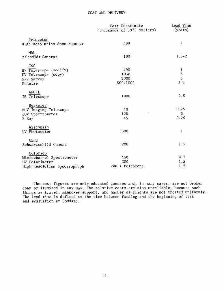
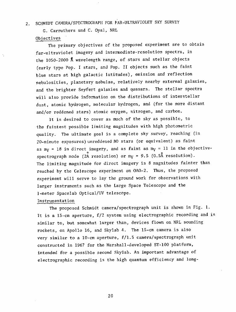
Conceptual view of an instrument package consisting of two Schmidt camera/spectrographunits mounted on a fine stabilized pointing platform. This package is mounted in theShuttle payload bay and is controlled from the shuttle cabin or pressurized Spacelab cabin.
24
3. UV TELESCOPE WITH ECHELLE SPECTROMETER
Y. Kondo and C. Wells, JSC
Objectives
The primary scientific objectives of this experiment are
investigations of stellar chromospheres, dynamics of extended
atmospheres of supergiants and WR stars, mass transfer in close
binaries including x-ray binaries, chemical abundance in stellar
atmospheres, and chemical abundance and electron temperature of
the interstellar medium. We are currently conducting a multi-year
program of spectrophotometry of astronomical objects in the
mid-ultraviolet through use of JSC's balloon-borne Ultraviolet
Stellar Spectrometer (BUSS). This project of payload development
includes the flight-tested JSC BUSS payload and the JSC/SRL
BUSS payload (SRL stands for Space Research Laboratory at Utrecht,
The Netherlands). The JSC/SRL BUSS payload with adaptations
constitutes the JSC/SRL Telescope Spectrometer for Spacelab
and is scheduled for a balloon flight in October 1975.
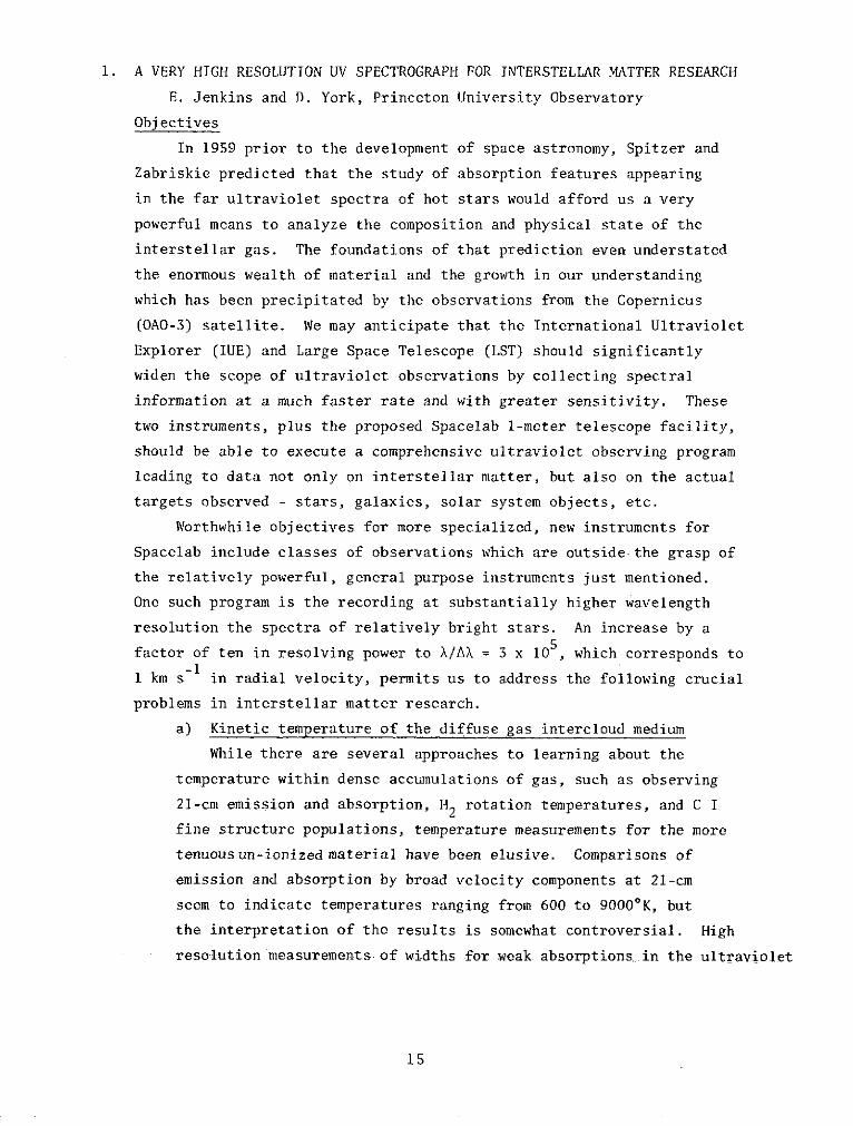
Instrumentation
The proposed system consists of the BUSS telescope and
star tracking system, supplemented with a high-resolution echelle
spectrograph and SEC vidicon detector supplied by SRL. The
instrument is shown schematically in figure 1. Total weight
is less than 400 kg, including star trackers and a gimbaled
mounting platform. The telescope is an f/7.5 tilted-aplanatic
design, which has been used successfully in previous BUSS mission
The telescope focal length is 3 meter, its aperture 40 cm. The
star tracker shown in the figure allows coarse pointing of the
entire telescope to one arc minute towards the target star,
while a further refinement of the pointing is accomplished by
an image motion compensation system with one arc sec stability
even if the shuttle attitude changes at 10/sec.
The spectrograph is of the echelle type, allowing the entireO
spectral region of 2000 - 3400 A to be observed simultaneously
by means of the SEC vidicon .detector. This is the fundamental
25
JSC SRL-BUSS SYSTEM CUTAWAY
MOUNTINGFRAME
DRIVECASE
STAR TRACKER SEC VIDICONLIGHT SHIELD DETECTOR
STAR TRACKER
SPECTROMETERCAMERA
CABLEOACCESS
SPECTROMETER
TORQUE MOTOR
SECONDARY MIRROR
BAFFLE
TELESCOPE LIGHTSHIELD
TELESCOPE INVAR TRUSS BAFFLE
STRUCTURE
PRIMAR SRROR CALIBRATION LAMP
DICHROIC MIRRORFINE POSITION
SENSORFigure 1.
difference in this instrument as compared with, for instance, S59,
BUSS, or OAO-3, where the spectrum is scanned step-by-step. The
UV light from the telescope is reflected by means of a dichroic
multilayer mirror into the spectrograph, while the transmitted
visible light of the star image is used for the image position
sensor. The main dispersing element of the spectrograph is an
echelle, with a blaze angle of 630.5 and a groove density of 79
lines/mm. The ruled area of the echelle is 102 x 206 mm, which
is illuminated by means of a 500 mm focal length collimator. ThisO o
design allows a spectral resolution at 2800 A of better than 0.1 A
even if the convolution of the telescope blur circle and fine
pointing errors of the telescope amounts to 3 arc seconds FWHM.
The limiting magnitude is about V=8m. The spectral range of
2000 - 3400 A is displayed in the spectrogram from the 112th0 O
order at 2000 A up to the 66th order at 3400 A. Reciprocal dispersions
range from 1.21 A/mm at 2000 A up to 2.05 A/mm at 3400 A. The
orders are separated spatially from each other by means of a
quartz predispersing wedge in such a way that the whole spectrogram
-is fitted optimally to the 25 x 25 mm target of the SEC vidicon
tube. The spectrograph will be equipped with a wavelength reference
source in order to allow in-flight wavelength calibrations. The
photometric response of the instrument will be determined by
means of pre-flight and post-flight calibrations in the laboratory.
Later improvements of the instrument include upgrading the spectral
resolution to 0.03 A, extension of the wavelength coverage to the
1150 to 3400 A, range and using the echelle spectrometer with a onemeter telescope.
Pointing and Other Spacelab Requirements
The pointing requirements are compatable with the requirements
for SIPS, but the complete pointing system of the BUSS makes it an
attractive candidate particularly for early shuttle flights, when
SIPS may not be fully operational.
The scientific data of the instrument will be stored on board
27
on magnetic tape. Housekeeping data analysis should be done
preferably on board, but could also take place on ground. Both
houskeeping and scientific data can be handled by the existing
computer facilities in Spacelab, or by a separate minicomputer
with 16 K of 16 bit words. Every orbit an average of ten tele-
vision frames of 8 Mbit each plus 1 Mbit of housekeeping data
have to be stored on magnetic tape. Housekeeping data will, together
with quick-look scientific data,be transmitted to the ground in
parallel at a bit rate of 48 Kilobits/sec in lieu of a specialist.
Tasks of the payload specialist would be:
a. To start automatic star acquisition software program
(once per orbit).
b. To start the measurement sequences software (once per
orbit).
c. To ensure proper data storage (changing tapes, etc.
regularly).
d. To take action in case of anomalies.
As a back up all commands can be generated also from the ground.
Additional Payloads
Two other instruments from JSC were discussed at the
workshop that exceed the guidelines for small payloads in
weight, size, or pointing requirements. The first was a 30-inch
Schmidt telescope with a package size ofl.2x 2.2 x 2.0 m and a
mass of 700 kg. The absolute pointing accuracy needed was only
6 arc min and internal stability is provided to 0.1 arc sec but
a roll stability of 2.5 arc sec is required. The second payload
was an Echelle Nebular Spectrograph with 1 x 1 x 2 m exterior
dimensions and a 300 kg mass. Pointing accurate to 1 arc sec
is needed with 0.3 arc sec stability.
28
4. SMALL INFRARED CRYOGENIC TELESCOPE
R. Walker, AFCRL
Objectives
The objective of this work is to obtain observational data
characterizing the spectral energy distribution of celestial objects
in the intermediate infrared, 4 to 30 microns. Specifically two
classes of observations would be performed.
A. Measurements of diffuse sources of large angular extent:
a) Thermal emission from interplanetary particles
(zodiacal emission) - A low resolution spectral and
spatial map of zodiacal emission would permit
identification of compositional classes (silicate,
iron, etc.) of the emitting particles and compositional
variations with distance from the sun.
b) Cosmic background radiation due to the aggregate of
unresolved galaxies - Definition of the spectrum of
the cosmic background in the middle infrared will
provide much selectivity in choices between steady
state and evolutionary models of the universe, and
provide needed data on the mean density of matter in
the universe.
c) Survey of galactic plane for extended regions of non-
thermal emission - A great variety of atomic and
molecular emission lines have been predicted for
regions where dust and gas are interacting, for
example:
H2 at 4.4, 5.0, 6.1, 8.0, 12 and 28 microns; Ne at
12.8, 15.4, and 14.3 microns; Fe at 26 microns.
A survey defining positions and intensity of these
regions would serve as a basis for a great many
detailed ground observations, and provide integrated
fluxes for the larger objects difficult to observe
from the ground.
29
B. Measurement of sources of small angular extent:
a) Selected Areas Survey - The present point-source IR
survey of AFCRL is complete to M(4) = 1,5, M(11) = 1
M(20) = -3 magnitudes for 80% of the sky and will add
significantly to our understanding of galactic structure.
The longer integration times available on orbit permits
observation of small regions, such as the Kapteyn Areas,
to a statistical limit 3 magnitudes fainter.
b) Extragalactic objects - Forty-four galaxies were observed
in the AFCRL sky survey. These observations indicate
that with the longer integration time available on
orbit, it will be possible to perform a detailed
survey of the Virgo cluster.
Instrumentation
The telescope (less gimbals) will fit within a cylinder
51 cm diameter by 137 cm long. The telescope should be free to view
in all directions, except that the optical axis of the telescope must
not approach closer than 300 to any spacecraft structure, the sun, the
moon or the Earth limb. The telescope will have a vacuum cover which
must be removed when in space. This will be by remote command (operator),
and the cover will be retained on the telescope or pallet for re-
installation at the completion of the mission.
The basic HI STAR rocket telescope would be modified by the
addition of an extended "sun shade" and by increasing the capacity
of the LHe dewar. The resulting cryogenic telescope would be mounted
in a fine-pointing two-axis gimbal to the spacelab pallet. Two modes
of operation are envisaged. In the first, the telescope would be
pointed to pre-selected celestial coordinates and remain at that
position for a predetermined length of time. In this mode the
internal chopper of the system would perform total modulation to
permit measurement of the absolute sky radiance. Spectral data
would be obtained by a multi-element detector array with a "wedge"
filter providing narrow wavelength band isolation. In the second
30
mode, the telescope would he pointed at preselected coordinates and
a reciprocating scan would be generated by the gimbals, Point
objects would be detected as they transit the detector elements.
Multi-band interference filters would isolate selected spectral
regions. In this mode surveys of the objects in selected areas
would be accomplished. Both modes of operation could be employed
on a single orbital mission, if desired.
Data from the multi-element array would be conditioned and
preprocessed by the "on-gimbal" telescope electronics. Data would
thus be transmitted to spacelab for further processing, recording and
transmission to the ground.
Pointing and Other Spacelab Requirements
A special gimbal mount is required to point the telescope
to within 1 are minute of the desired celestial coordinate and maintain
that line of sight with a stability of 20 arc seconds, peak to peak.
In addition, the gimbal should be able to scan at rates on the order
of several degrees/sec with a constancy of 1% of the scan rate. Scan
amplitudes should be adjustable in the range 1 to 300. Positional
readout during scan should be accurate to ± 20 arc seconds.
Scan mode will require a special purpose memory unit with 16
bit word size capable of co-adding 30 input channels at the rate
of 2000 words per second per input channel. Input words would be
14 bit length, (60K, 16 bit memory). Computer memory would be
dumped at completion of area scan, and stored information further
processed by on board computer to produce coordinates and amplitudes
of sources detected. This can be easily accomplished with a com-
putation rate of 2000 per second and a memory of 10 K. Total
data to be "dumped" to ground in one day is determined by number
of sources detected. Total is estimated at 105, 10 bit words/day
106 bits/day (max.).
For all the observations desired, the orbit should be above
400 km altitude. A variety of orbital inclinations and launch times
is desired, depending upon the main objectives of the flight. For
31
example: an inclination of 280 would optimize observation of the
regions near the galactic poles, while a sun-synchronous polar orbit
would provide the best environment for scanning selected areas.
The telescope would consume 18 kgs. of stored liquid helium
during a seven day mission. The LHe would be stored in the telescope
dewar at a pressure of 3 atm. The boil-off gases could be exhausted into
the local environment if this would not compromise other payloads on
the mission.
Manned support would be required to operate the telescope
and gimbals. It is assumed that pointing would be through interface
with the spacelab computer and aspect reference system.
Of special concern to the infrared experiment is the cleanliness
of the local environment. Class 5000 should be maintained in the un-
pressurized section. Effects of reaction jets is not known at this
time; however, it is estimated that emission rates for particles
10-25 microns in diameter should be kept below 15/minute, if possible,14 2
and the H20 vapor column density should not exceed about 1014/cm
Space chamber tests of the first system would be highly
desirable. The chamber should have an internal cold limer at T 200 K.
32
5. TWO EUV EXPERIMENTS
S. Bowyer, University of California at Berkeley
A. EUV Imaging Telescope
A number of classes of galactic objects have been predicted to
emit the bulk of their radiation in the EUV band between 100 andO
1000 A. This instrument will be capable of detecting such sources
and locating their positions to within 10 are minutes. If any
extended EUV sources are discovered, this experiment can map them
by simple pointing maneuvers. In addition, the spectral bandpass
may be changed by placing different filters in front of the detector.
The great strength of this experiment lies in its imaging
ability. In the EUV, the largest source of background is the resonant
fluorescence of solar photons with the gases of the Earth's atmosphere.
Thus, this radiation is diffuse, and appears distributed over the
image plane. A point source, however, remains confined to one resolution
element on the image plane. The net result is that the signal to
noise ratio rises by the number of resolution elements, which is
typically 1000.
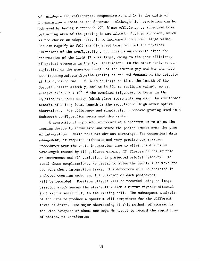
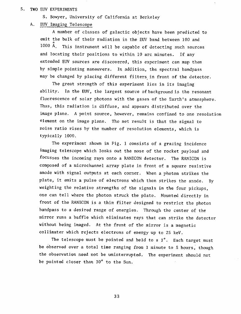
The experiment shown in Fig. 1 consists of a grazing incidence
imaging telescope which looks out the nose of the rocket payload and
focusses the incoming rays onto a RANICON detector. The RANICON is
composed of a microchannel array plate in front of a square resistive
anode with signal outputs at each corner. When a photon strikes the
plate, it emits a pulse of electrons which then strikes the anode. By
weighting the relative strengths of the signals in the four pickups,
one can tell where the photon struck the plate. Mounted directly in
front of the RANICON is a thin filter designed to restrict the photon
bandpass to a desired range of energies. Through the center of the
mirror runs a baffle which eliminates rays that can strike the detector
without being imaged. At the front of the mirror is a magnetic
collimater which rejects electrons of energy up to 25 keV.
The telescope must be pointed and held to * 10. Each target must
be observed over a total time ranging from 1 minute to 5 hours, though
the observation need not be uninterrupted. The experiment should not
be pointed closer than 300 to the Sun.
33
COLLI MATOR
11111& IIIIII
B MAGNETSAFF
EE0
MIRROR
FILTER
E " RANICONLE " ACCESS PORTC
: i To RS0O UMBILICAL
N
CS1S * "'ACCESS PORT
MOUNTING RING43.8 cm
FIGURE 1.
SCHEMATIC OF EUV TELESCOPE
34
The experiment needs a bit rate of 20 Kbps when operating.
Either direct telemetry or on board storage is acceptable. A record
of the spacecraft aspect is required; 3 0F accuracy is required, 5'
accuracy is desirable. Note that this is only a recording requirement
and is not a pointing requirement. There will be a door on the side
of the shell to allow access to electronics. This will be shut and
not used during flight.
Four analogue outputs should be monitored intermittently either
on board or on the ground. These outputs are:
i) Total Counting Rate
ii) RANICON voltage
iii) Pressure
iv) Current
B. EUV Spectrometer
The primary scientific goals of the EUV Spectrometer are summarized
in the following four areas.
a) Geocoronal Airglow
The total existing data on both the atmospheric dayglow and0
nightglow in the range from 300 to 1050 A is limited to a small
number of measurements made with broadband photometers (AX ' 300 A)
made with sounding rockets. The interpretation of these data is
by necessity restricted, as it is based on assumptions as to the
wavelengths of the radiation being observed. No moderate or
high resolution studies have been made at these wavelengths and
no spatial or temporal studies have been carried out. Extreme
ultraviolet airglow measurements which should be carried out with
the instrumentation include an exploratory search of the EUV band
of the spectrum (300 to 1050 A) to detect with high sensitivity
all resonantly scattered and collisionally excited radiation
and a search for locally enhanced regions produced as a result of
specific sources of collisional excitation.
b) Aurora
The need of remote sensing of auroral phenomena becomes
evident when one considers the vast scale, in both time and
space, of the necessary measurements. Without considering details,
it is obvious that adequate coverage of the aurora using only
35
in situ observations is nearly impossible even with a relatively
large number of satellites and rockets. Fortunately, the aurora
by its very nature is amenable to study by remote sensing techniques.
This characteristic contributes to the fact that the aurora is
probably the most useful phenomenon for use in efforts to experimentally
explore both the magnetosphere and the ionosphere. Currently no
auroral EUV spectrum exists.
c) Plasmasphere
The Hell 304 A line is optically thin at Shuttle altitudes
and plays a unique role as a tracer for the plasmasphere. A
study of this radiation will facilitate our understanding of the
nature of this region and its interaction with the magnetosphere.
Observations of this line will permit detailed evaluations of
competing models of the plasmasphere as was carried out by Paresce,
Bowyer and Kumar (J.G.R., 79, 174, 1974). Number densities of
ionized helium derived from this data may be more reliable than
number densities derived from mass spectrometer data because of
various experimental difficulties inherent in measurements with
in situ detectors.
d) Local interstellar medium
It is now well established that the study of resonantly scattered
584 A radiation from neutral helium will be central in our developing
knowledge of the interaction of the local interstellar medium with
the solar system. By the time of the Shuttle these studies should
have delineated many of the parameters of this interaction, but it is
likely that some effects such as changes with solar cycle and trace
element measurements will not be fully explored. Studies of 584 A
Hel and 1025 A HI radiation will delineate these interactions and
studies of other EUV lines such as predicted by Blum, Fahr, Axford,and
others will define the trace element interactions.
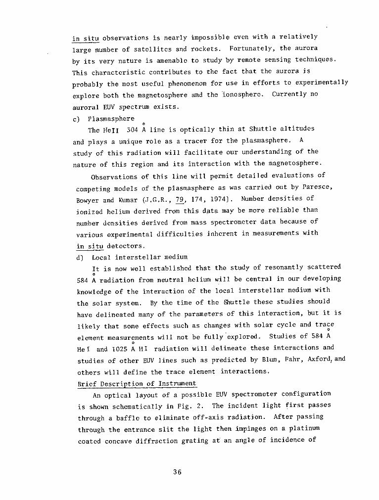
Brief Description of Instrument
An optical layout of a possible EUV spectrometer configuration
is shown schematically in Fig. 2. The incident light first passes
through a baffle to eliminate off-axis radiation. After passing
through the entrance slit the light then impinges on a platinum
coated concave diffraction grating at an angle of incidence of
36
SIDE VIEW
COLLIMATOR
INCIDENT LE
BEAM
80 A O,
RANICON GRATING u
DETECTOR
FIGURE 2. ZERO ORDER
EUV LIGHT TRAPSPECTROMETER SL ROWLAND
CIRCLE
TOP VIEW
'110° The grating is an off the shelf Bausch and Lomb replica ruled
at 2400 lines/mm, blazed at 1000 A and having a radius of 400.7 mm.
The diffracted radiation is focused by the grating onto a RANICON
situated on the Rowland circle. The inside order spectrum is used
for packaging convenience. The RANICON serves as an efficient position
sensitive EUV photon counter and consists of a 75 mm diameter channel
electron multiplier array followed by a resistive anode. The front
face of the CEM array is the photocathode, where photoelectrons are
generated; an individual electron is multiplied about 107 times in
traveling the length of a channel. The close spacing of adjacent
channels permits good spatial resolution of an EUV spectral image.
Each electron pulse produced by the CEM array is proximity focused
onto the resistive anode. This anode is connected to low noise charge
sensitive amplifiers, whose relative output pulse amplitudes give the
location of the detected photon. The image is accumulated in a small
random access memory for periodic readout.
The pointing requirements depend on the scientific objective.
a) Geocoronal airglow: random or programmed sweeps of overhead
sky (1 to 50/second) to accuracy of + 100.
b) Aurora: programmed sweeps of auroral arcs (10 to 50/second);
pointing at one geographical point (± 02) for duration of
overhead pass.
c) Plasmasphere: programmed scans (1 to 50/second) to accuracy
of ± 50
d) Interstellar medium: random pointing or programmed sweeps of
sky within + 400 of zenith.
A record of the aspect is required with 10 accuracy. A maximum data
rate of 40 K bps for intervals of 5 minutes is required for auroral
observations. At other times, a maximum of 10 K bps is needed. The
experiment must be purged with dry nitrogen until shortly before
launch (typical flow rate: 1 cubic foot per hour).
C. X-Ray Payload
A high-time resolution x-ray experiment was also discussed. The
Spacelab requirements for pointing and power were similar to those
of the EUV payloads. A data rate of 200 K bps, 3 deploying doors, and
gas supply bottles are included as special needs.
38
6. ULTRAVIOLET PHOTOMETER
A. Code and R. Bless, University of Wisconsin
Objectives
The purpose of this experiment is to establish the absolute energy
calibration for a net of about 40 early-type stars in the spectral interval
925 to 3400 A. Any member of this group of carefully measured stars would
serve as a secondary standard of absolute flux for other UV telescopes in
orbit.
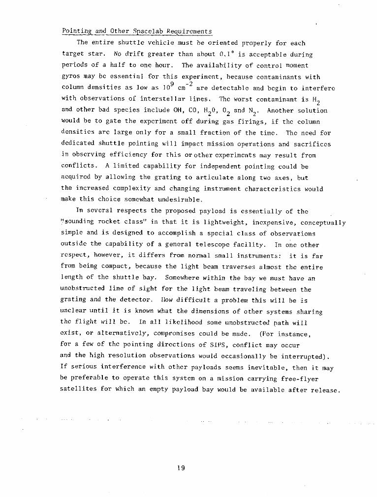
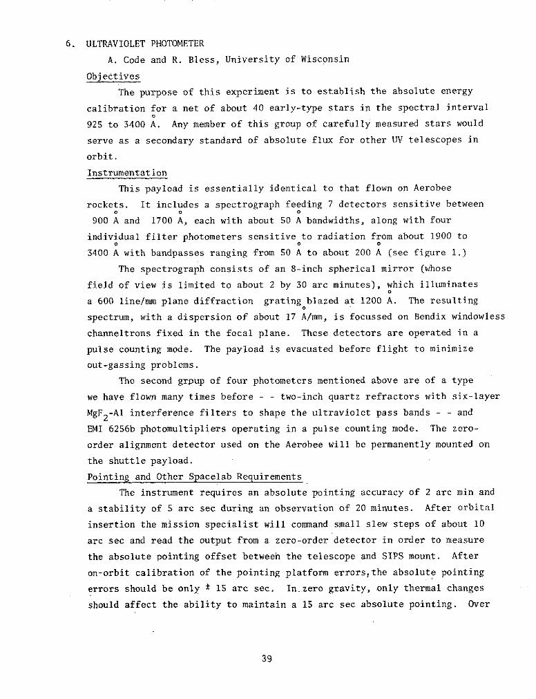
Instrumentation
This payload is essentially identical to that flown on Aerobee
rockets. It includes a spectrograph feeding 7 detectors sensitive betweeno 0 0
900 A and 1700 A, each with about 50 A bandwidths, along with four
individual filter photometers sensitive to radiation from about 1900 toO 0 0
3400 A with bandpasses ranging from 50 A to about 200 A (see figure 1.)
The spectrograph consists of an 8-inch spherical mirror (whose
field of view is limited to about 2 by 30 arc minutes), which illuminates
a 600 line/mm plane diffraction grating blazed at 1200 A. The resulting
spectrum, with a dispersion of about 17 A/mm, is focussed on Bendix windowless
channeltrons fixed in the focal plane. These detectors are operated in a
pulse counting mode. The payload is evacuated before flight to minimize
out-gassing problems.
The second grpup of four photometers mentioned above are of a type
we have flown many times before - - two-inch quartz refractors with six-layer
MgF2-Al interference filters to shape the ultraviolet pass bands - - and
EMI 6256b photomultipliers operating in a pulse counting mode. The zero-
order alignment detector used on the Aerobee will be permanently mounted on
the shuttle payload.
Pointing and Other Spacelab Requirements
The instrument requires an absolute pointing accuracy of 2 arc min and
a stability of 5 arc sec during an observation of 20 minutes. After orbital
insertion the mission specialist will command small slew steps of about 10
arc sec and read the output from a zero-order detector in order to measure
the absolute pointing offset between the telescope and SIPS mount. After
on-orbit calibration of the pointing platform errors,the absolute pointing
errors should be only * 15 are sec. In zero gravity, only thermal changes
should affect the ability to maintain a 15 arc sec absolute pointing. Over
39
2" Photometers
Baffle
,,,-Star tracker
Grating
----Telescope
ORIGINAL PAGE ISOF POOR QUALITy
8" Mirror Detectors
Electronics
Figure 1. Wisconsin far UV spectrometer payload including fourbroadband photometers.
40
1 week mission we want to observe bright stars spaced over 1 hemisphere
of the sky twice. Do not observe in sunlight; close shutter when near
sun. Strict cleanliness precautions are necessary for calibration
payloads and dry nitrogen will probably be required for purging during
launch and re-entry.
Data is recorded by an on-board computer and transmitted via
TDRS whenever possible. Check-out phase (1-3 orbital nights): payload
commanded by mission specialist must have voice contact during this
period; otherwise, we must have real-time data link. During the first
day we should have several data dumps to control center. After the first
day, one dump per day is sufficient.
After check-out the payload can be operated automatically from pre-
programmed commands. These should be capable of quick revision. Since
there are no movable mechanisms in this particular spacelab payload, control
of the experiment can be relatively simple namely: turn on/off experiment
low voltage, turn on/off experiment high voltage, turn on/off calibration
lamp. Total lines needed: 3.
However, to take advantage of the power of spacelab's command
ability a more flexible and safer (in the event of a payload subsystem
failure) command sequence can be used with only a small increase in
hardware. Each of the 12 detectors, counting the zero order detector,
can be individually enabled or disabled through redundant payload hardware.
Each detector would require 2 command lines, i.e., enable/disable detector
LV and enable/disable detector HV. Additional command lines would be needed
to provide LV to housekeeping circuitry, calibration lamp power supply
and shutter open/close, zero-order detector field stop, and nitrogen purge
on/off. Total command lines required: 30.
We would like about one month as close to flight as possible to recalibrate
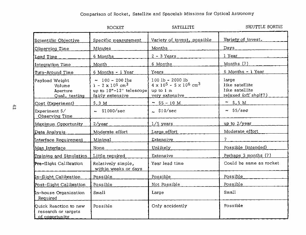
payload.The following table summarizes our thoughts on some of the important
parameters of a Spacelab flight. In order to maintain the basic philosophy
of the sounding rocket program which has been quite successful over the years,the Spacelab support systems should be designed to satisfy the goals listed
in the final column.
41
Comparison of Rocket, Satellite and Spacelab Missions for Optical Astronomy
ROCKET SATELLITE SHUTTLE SORTIE
Scientific Objective Specific measurement Variety of invest. possible Variety of invest.
Observing Time Minutes Months Days
Lead Time 6 Months 2 - 3 Years 1 Year
Integration Time Month 6 Months Months (?)
Turn-Around Time 6 Months - 1 Year Years 6 Months - 1 Year
GENERAL 0.76 1.27 - 45.4 30 50 .000 DC 273 313 273 313PURPOSEUVTELESCOPE
For the second study mission, the UV pallet and its payload was
replaced by a single palleti carrying the UV facility-class (1-meter) telescope
mounted on the ESRO Instrument Pointing System (IPS). As a result of the
volume occupied by this instrument, it was necessary to reduce the High
Energy Astrophysics payload to a single instrument, HE-1, while still
including the Solar Physics payload.
The third study mission, for studying the combination of a deployable
free flyer and a pallet payload, included the UV Astronomy payload of two
instruments plus a typical free flyer. The Solar Maximum Mission (SMM) was
chosen as a representative deployable free flyer.
61
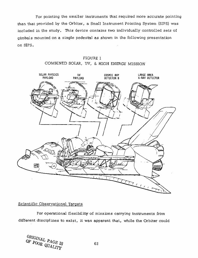
For pointing the smaller instruments that required more accurate pointing
than that provided by the Orbiter, a Small Instrument Pointing System (SIPS) was
included in the study. This device contains two individually controlled sets of
gimbals mounted on a single pedestal as shown in the following presentation
on SIPS.
FIGURE 1
COMBINED SOLAR, UV, & HIGH ENERGY MISSION
SOLAR PHYSICS UV COSMIC RAY LARGE AREAPAYLOAD PAYLOAD DETECTOR B X-RAY DETECTOR
;--- . ",. ,
1 z 7/ ~r --J .
Scientific Observational Targets
For operational flexibility of missions carrying instruments from
different disciplines to exist, it was apparent that, while the Orbiter could
O.&IGIN'o AGZ 62)WUALI7y6
be used for coarse pointing, simultaneous and independent observations
with the various instruments would be necessary. Accordingly, a series of
targets considered scientifically desirable for observations was developed by
scientists in the three disciplines. These targets are shown in Figure 2,
using an ecliptic coordinate system. Solar Physics requires solar viewing
orientations, while the majority of the High Energy Astrophysics targets in
this study resulted from requirements of the X-Ray experiment. It was desired
to obtain 105 seconds of observations of the Andromeda Nebula (M-31), to
scan the Vela remnant in a 6 x 6 scan matrix (36 individual matrix element
observations of 23 minutes), and to scan the galactic plane in 10 steps, plus
other targets as possible. Requirements of the Cosmic Ray Experiment were
not as severe, it being desired that the instrument field of view not be occulted
by any part of the Earth. UV Astronomy targets included 25 locations distributed
over the sky. Of these 25 targets, 5 were first priority, with the remainder
as second priority targets.
Orbit
A 200 n mi circular orbit at 28. 50 inclination, with the launch timed
to minimize inclination of the orbit to the ecliptic and allow simultaneous Vela
and sun viewing, was considered. To maximize scientific data acquisition,
24 hours/day operation was considered. A six man crew, including 3 Payload
Specialists for continuous observations, was included. One revolution per
day was set aside for housekeeping purposes. By selecting a basic orientation
of the Orbiter X-axis (longitudinal-axis) perpendicular to the ecliptic plane
(X-PEP), except when making observations with HE-1, the large X-Ray Detector,
and observations of the UV polar sources, it was possible to observe most
targets with periodic roll/pitch maneuvers requiring about 6 minutes.
63
FIGURE 2
MISSION GEOMETRY AND SUMMARY PROFILE
Combined UV, Solar, High Energy Sortie Mission
ECLIPTIC COORDINATES ORBIT ORIENTATION
TARGETS
SUN SUN 0- 180, X - 0M-3t 0- 325, X - 37VELA 0- 139, X - -62 ,GALACTIC 0- 34, X 0 "PLANE ODE
UV SOURCES._ 0 - 0, 90 \/ECLIPTIC PLANE
PRIORITY 270 x - -45
= 0 - ± 45 1 =I P45& X - 0, ± 45P 90 &X - 0, -45
2ND P- 135 & X - 0, t 45 ORBIT INCLINATION MINIMIZEDPRIORITY |, 180 & - 145 TO ECLIPTIC
p= 225 & X - O, 45 TIME OF YEAR SELECTED FOR
S= 270 & X - 0, +45 SIMULTANEOUS VELA t SUN VIEWING
= 315 & x - 0, ± 45 LAUNCH 9.37 HR, 28 JULYBASIC SYSTEM OPERATIONAL CRITERIA
200 x 200 NMI ORBIT, INCL 28.5 DEG24 HR PER DAY OPERATIONS (6 MAN CREW, 3+3)1 REV PER DAY FOR HOUSEKEEPING (OVER SAA)BASIC ORIENTATION: X-AXIS PERP TO ECLIPTIC PLANE EXCEPT FOR HE-I& UV POLAR SOURCES
P/L OPNL MODE
36 REVS 9 REVS 5 REVS 10 REVS 19 REVS 10 REVS
FIRST & LAST 7 REVS FOR SETUP & SHUTDOWN
S 1 2 3 4 5 6 7DAYS
Operational Time Lines
For the 7-day duration of Mission 1, a time line of 5 different modeswas established for 6 operational days, the first half and last half missiondays being set aside for setup and checkout after launch and stowage anddescent preparations prior to return.
Mode 1, shown in Figure 3 fora 2 revolution duration, was performedto prioritize X-ray observations. Periods of Andromeda and Vela pointing andthe maneuvering times to change targets are shown. For HE-i, the actual timeswhen the Vela/Andromeda sources would fall in the instrument field of view are
64
shown. Also shown are the times when the Orbiter-Z axis would coincide with
the sun line-of-sight (LOS). Around these times are then shown the times
within which Solar Physics instruments, SIPS-mounted, could track the sun or
UV Astronomy instruments also SIPS-mounted, could observe. Significant
periods of solar and UV astronomy observations occur. In addition, since the
Orbiter Z-axis is pointed away from the Earth during this time, cosmic ray
observations are practically continuous. An estimated 10 percent outage of
Tracking and Data Relay Satellite (TDRS) coverage per orbit is also shown.
FIGURE 3X-RAY OBSERVATIONS (MODE 1)
EXPERIMENT OPERATIONS
UV-1 . I I I I I I
UV-2 I I I I1 1 I
HE-3 -
SO-1 I ISO.2 I I I50-3 I I
TDRS OUTAGE(0.14 HRS)
ANDR PT VELA PT ANDROMEDA PT VELA PT ANDR PT
ROLL/PITCHMANEUVER(0.1 HRS)
IVELA VELAANDROMEDA ANDROMEA ANDROMEDA
SI SUNLOS I SUN1 LOIl * I , I ,12 13 14 1S
TIME, HRS
Mode 2 was prioritized for 9 revolutions of observations of combined
Solar Physics and first priority UV Astronomy targets. No observations with
the X-ray detector are programmed, while again the cosmic ray experiment has
65
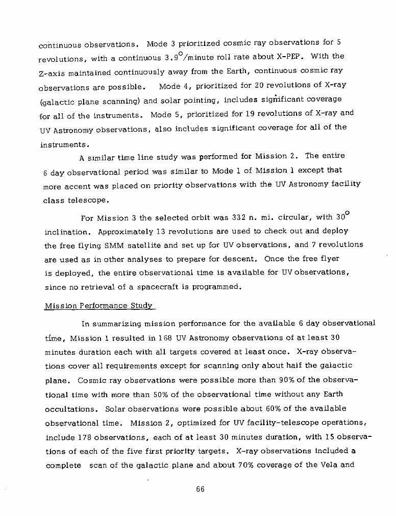
continuous observations. Mode 3 prioritized cosmic ray observations for 5
revolutions, with a continuous 3.9 0 /minute roll rate about X-PEP. With the
Z-axis maintained continuously away from the Earth, continuous cosmic ray
observations are possible. Mode 4, prioritized for 20 revolutions of X-ray
(galactic plane scanning) and solar pointing, includes significant coverage
for all of the instruments. Mode 5, prioritized for 19 revolutions of X-ray and
UV Astronomy observations, also includes significant coverage for all of the
instruments.
A similar time line study was performed for Mission 2. The entire
6 day observational period was similar to Mode 1 of Mission 1 except that
more accent was placed on priority observations with the UV Astronomy facility
class telescope.
For Mission 3 the selected orbit was 332 n. mi. circular, with 300
inclination. Approximately 13 revolutions are used to check out and deploy
the free flying SMM satellite and set up for UV observations, and 7 revolutions
are used as in other analyses to prepare for descent. Once the free flyer
is deployed, the entire observational time is available for UV observations,
since no retrieval of a spacecraft is programmed.
Mission Performance Study
In summarizing mission performance for the available 6 day observational
time, Mission 1 resulted in 168 UV Astronomy observations of at least 30
minutes duration each with all targets covered at least once. X-ray observa-
tions cover all requirements except for scanning only about half the galactic
plane. Cosmic ray observations were possible more than 90% of the observa-
tional time with more than 50% of the observational time without any Earth
occultations. Solar observations were possible about 60% of the available
observational time. Mission 2, optimized for UV facility-telescope operations,
include 178 observations, each of at least 30 minutes duration, with 15 observa-
tions of each of the five first priority targets. X-ray observations included a
complete scan of the galactic plane and about 70% coverage of the Vela and
66
Andromeda targets. Solar observing totalled about 65% of the available observa-
tional time. Mission 3, once SMM was deployed, of course resulted in
excellent UV Astronomy coverage.
Reaction Control System (RCS) Operation
From the operational aspects of the Orbiter, propellant usage does
not appear to be a problem for the missions studied. Mission 1 required
approximately 4400 pounds of the available 6040 pounds of Shuttle propellant.
For all these missions of 7 days, it should be noted that approximately 50%
of the propellant was used for payload operations, the remainder for ascent/
descent and setup/shutdown/housekeeping (See Table 2).
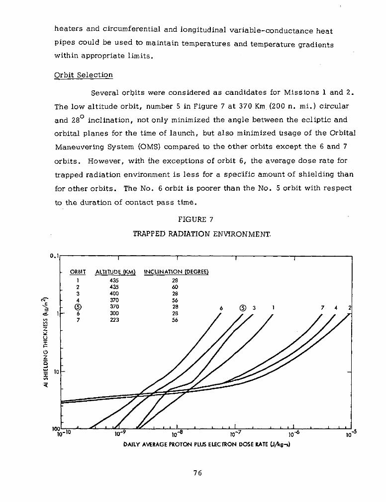
DAILY AVERAGE PROTON PLUS ELECTRON DOSE RATE (J/g-s)
76
SMALL INSTRUMENT POINTING SYSTEM (SIPS)
C. Henrickson, Ball Brothers Research Corp.
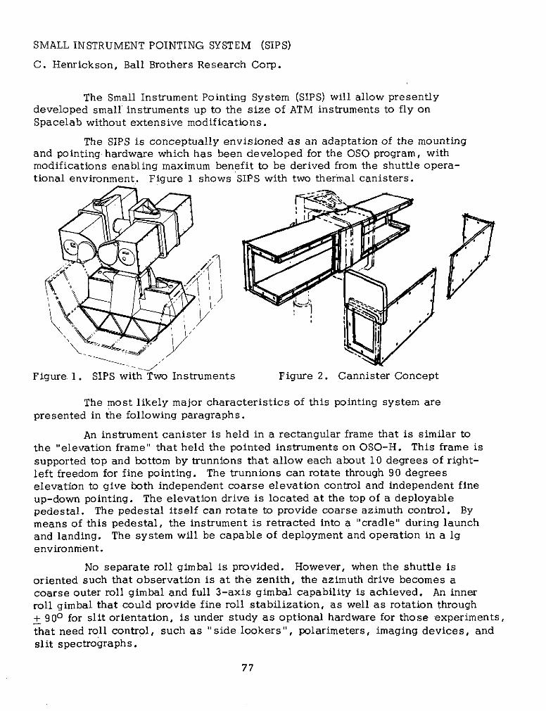
The Small Instrument Pointing System (SIPS) will allow presentlydeveloped small instruments up to the size of ATM instruments to fly onSpacelab without extensive modifications.
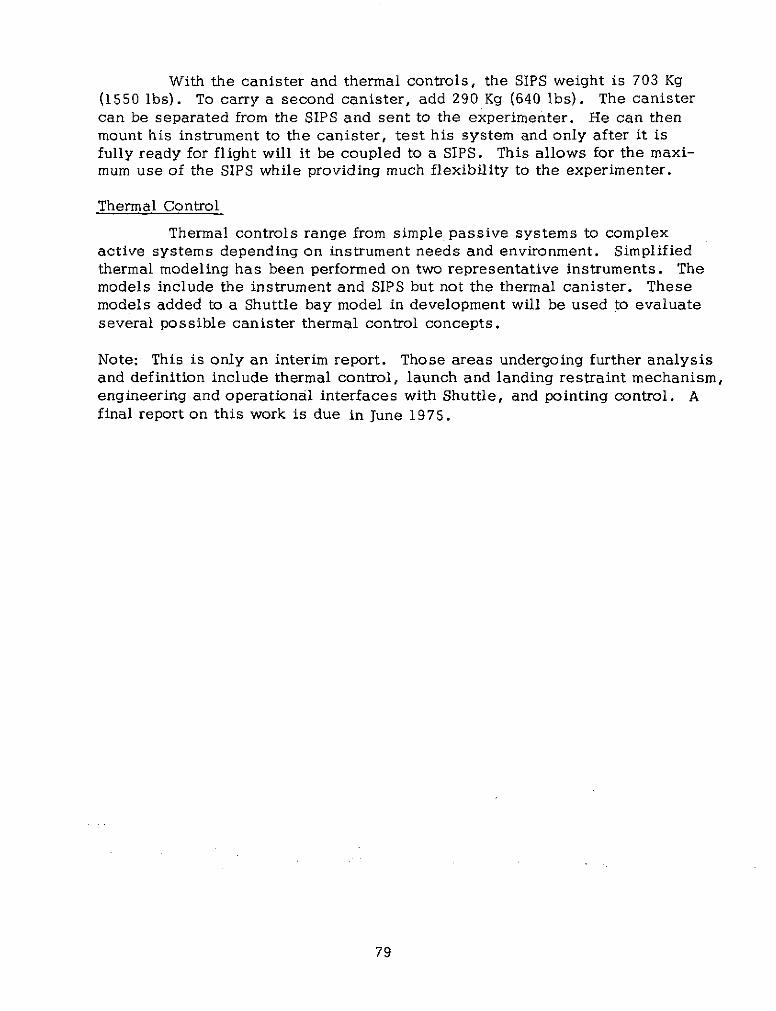
The SIPS is conceptually envisioned as an adaptation of the mountingand pointing hardware which has been developed for the OSO program, withmodifications enabling maximum benefit to be derived from the shuttle opera-tional environment. Figure 1 shows SIPS with two thermal canisters.
Figure 1. SIPS with Two Instruments Figure 2. Cannister Concept
The most likely major characteristics of this pointing system arepresented in the following paragraphs.
An instrument canister is held in a rectangular frame that is similar tothe "elevation frame" that held the pointed instruments on OSO-H. This frame is
supported top and bottom by trunnions that allow each about 10 degrees of right-left freedom for fine pointing. The trunnions can rotate through 90 degreeselevation to give both independent coarse elevation control and independent fineup-down pointing. The elevation drive is located at the top of a deployablepedestal. The pedestal itself can rotate to provide coarse azimuth control. Bymeans of this pedestal, the instrument is retracted into a "cradle" during launchand landing. The system will be capable of deployment and operation in a lgenvironment.
No separate roll gimbal is provided. However, when the shuttle is
oriented such that observation is at the zenith, the azimuth drive becomes acoarse outer roll gimbal and full 3-axis gimbal capability is achieved. An innerroll gimbal that could provide fine roll stabilization, as well as rotation through+ 900 for slit orientation, is under study as optional hardware for those experiments,that need roll control, such as "side lookers", polarimeters, imaging devices, andslit spectrographs.
77
It should be noted that this mount would usually accommodate two
separate fine-pointing instruments, supported on opposite sides of the pedestal
pedestal, as shown in Figure 1. The two systems would share deploymentand coarse azimuth control but could pursue observations of either different
or identical points lying within a strip of about 10 x 90 degrees.
The SIPS canister is sized to accommodate instruments with dimen-
sions up to 91.4 x 91.4 x 315 cm (36 x 36 x 124 in). These dimensions will
allow any instrument up to ATM size to be enclosed. The upper limit on
weight handling is expected to be about 340 Kg (750 lbs). The inner roll gimbal
should hold standard Aerobee payloads (38 cm in diameter) and, hopefully,
Aerobee 350 payloads (56 cm in diameter).
Pointing Capability
The SIPS can operate in either of two modes. The first is an "open
loop" mode in which the shuttle orbiter serves as a reference. The second
is a "closed loop" mode in which sensors on or in the instrument serve as
the pointing reference.
In the open loop the SIPS is pointed using information from the
Orbiter's navigation systems. The gimbals are then locked with respect to
the Orbiter and the pointing is done by the Orbiter. Accuracy is dependent
on the inherent pointing capability of Orbiter and the distortion of the Orbiter
due to the thermal variations and gradients. Accuracy will probably be
limited to several degrees.
In the closed loop mode, accuracy and stability can be extremelygood depending principally on the type of reference sensor(s) used. With
or star trackers using bright stars), stability of 1 arc-sec should be possible.The absolute accuracy will depend directly on the sensor complement for aparticular instrument, but should be on the order of an arc minute with a
package that includes a star tracker and good rate integrating gyros.
Environmental Canister
The canister will provide protection from shuttle-borne contaminationand will also facilitate instrument temperature control. Ideally, it will accom-
modate existing instruments without modification of their tie-down fixtures.
The canister's basic structure can be in the form of a channel, as shown in
Figure 2. ATM instruments (and others of that size) can be tied down to thethicker base wall (bottom of the "U") using the original non-redundant fix-tures. Alternatively, if the instrument is sufficiently stiff, it may be hardattached to the base wall with small dimensions between the attachment points.
78
With the canister and thermal controls, the SIPS weight is 703 Kg(1550 lbs). To carry a second canister, add 290 Kg (640 Ibs). The canistercan be separated from the SIPS and sent to the experimenter. He can thenmount his instrument to the canister, test his system and only after it isfully ready for flight will it be coupled to a SIPS. This allows for the maxi-mum use of the SIPS while providing much flexibility to the experimenter.
Thermal Control
Thermal controls range from simple passive systems to complexactive systems depending on instrument needs and environment. Simplifiedthermal modeling has been performed on two representative instruments. Themodels include the instrument and SIPS but not the thermal canister. Thesemodels added to a Shuttle bay model in development will be used to evaluateseveral possible canister thermal control concepts.
Note: This is only an interim report. Those areas undergoing further analysisand definition include thermal control, launch and landing restraint mechanism,engineering and operational interfaces with Shuttle, and pointing control. Afinal report on this work is due in June 1975.
79
POINTING
W. Nagel, GSFC
In addition to the SIPS, there are two other pointing systems planned.
As a result of the Small Payloads Workshop, a third system is being studied.
Orbiter
The orbiter can be used as a pointing system. The inputs to the con-
trol system can be either from the navigation system or from sensors mounted
on the pallet or the instrument. If the inputs of the navigation system are used
for pointing, there will be the errors inherent in the navigation system pluserrors due to distortions of the Shuttle from temperature gradients and mechanicaldistortion at the pallet. This latter source of error may lead to accuracies ofno better than 20 - 40 . Using a pallet mounted star tracker and observingcelestial targets, pointing accuracy improves to + 0? 3 5 , with 0.10 deadband.
Instrument Pointing System (IPS)
The IPS is a system being studied capable of pointing large, heavy
payloads accurately. Several arrangements have been investigated for the IPS.A conventional gimbal arrangement, an inside out gimbal arrangement and asuspended pallet concept.
Any of these would be automatically controlled by the computer utili-
zing on-board sensors. Table 1 lists some of the requirements for IPS.
Table 1
Requirements for IPS
* Pitch and Yaw Pointing Accuracy +1 s 30" Pitch and Yaw Pointing Stability +1 se 3a* Roll Pointing Accuracy +30 sec 3c" Roll Pointing Stability +10 -e 30
* Slew Rate 30 deg/min* Gimbal Range +500 Pitch and Yaw +900 Roll* Size Payload 2 M Dia x 6 M Long• Weight 3000 KG
Tiny Instrument Pointing System (TIPS)
The Workshop brought out the need for a less sophisticated pointing
system than either IPS or SIPS with weight carrying capabilities considerably
reduced from either. As a result of these needs the concept of TIPS. has been
introduced with accuracy of 1 arc-minute and stability of 10-15 arc-seconds.
It will have 3-axes and support about 100 kg.
80
MECHANICAL
D. Miller, GSFC
Payload Attachment Location in Payload Bay
Thirteen (13) primary payload structural attachment points are providedalong the payload bay. With the exception of the aft most position, eachattachment consists of three points, one on each longeron and one at the keel.The aft attachment consists of attachment points on the two longerons, butnone at the keel. The attachment points in Spacelab are identified in blue-prints. The allowable reaction loads which may be reacted in each direction(X,Y, Z) at each primary attachment point are shown in Figure 7-20 of Reference'1.
Pallet Attachment
There are 24 hard points for payload attachment on each pallet. Thehard points are ball/socket joints bolted to the pallet structure having loadcarrying capability of:
X direction 2910 kgY direction 1880 kgZ direction 7650 kg
Figure 1 demonstrates typical use of hard points.
THREE POINT TYPICAL SUPPORTATTACHMENT STRUCTURE SUPPORT STRUCTURE PALLET
ATTACHMENT
ARINGACHMENT
HARL JOINT
FRAME LOOR PAE PALLET
HARDPOINTS SILL LEVELUTILITYPLATFORM SUPPORT
STRUCTURE
HAROPOINTS HARDPOINTS
LOW LEVEL EXPERIMENTUTILITY PLATFORM BASE PLATE
Figure 1. Typical Use Of Hard Points
-/"Space. Shuttle System Payload Accommodations", JSC 0770, Vol. XIV,Rev. C., JSC, July 3, 1974.
81
Pallet Description
The pallet's cross-section is U-shaped and is made of aeronautical
shell-type construction. It provides hard points for mounting heavy experiments
and a large panel surface area to accommodate various payload configurations.
The pallets are modular (3 M nominal length) and can be flown independently orinterconnected. As many as three pallets can be interconnected.
To increase the surface mounting area and particularly the viewing
capability of the pallet, additional experiment utility platforms can be provided
as shown on Figure 1. Two types of platforms are proposed: one 1. 5 meterswide and mounted horizontally at sill level, the other 1. 5 meters wide and
mounted horizontally at the first frame kink (from the top) of the pallet. In
both cases the platforms can be mounted between any two main frames (notend frames) whether or not the pallet segments are rigidly connected or
separately suspended. The platforms are flat and consist of a grid of beamscovered with honeycomb sandwich panels, in a similiar manner to the pallet.The intersections of the pallet beams provide mounting for hard points to
accommodate heavy pieces of equipment while lighter experiments are attached
via inserts in the snadwich panels (8 mm diameter honeycomb inserts withmetric self-locking thread at any requested hole pattern).
The pallet floor has a limited load capability and precautions will benecessary to avoid damage. Pressures are limited to 50 Kg/M 2 . Figure 2shows a basic two pallet configuration with igloo, forward utility bridge andother pallet features. The igloo is a cylinder with controlled temperature andpressure (N2 atmosphere) capable of containing the following data managementand power distribution equipment:
3 computers2 I/O units1 mass memory3 subsystem RAUs3 experiment inverters (50, 60, and 400 Hz)1 subsystem inverter1 emergency inverter1 power battery and bit1 power control box1 secondary power distribution box1 caution and warning logic
The same igloo structure, although designed for subsystem installation,is offered to the user as an option for experiment-peculiar equipment installation(e.g., experiment support container). In this option, the igloo is mounted to thepallet floor.
82
LIFTING LUGSFOR GROUNDHANDELING
INTERFACECONNECTORS
EXPERIMENT I STRUCTURALSTRUCTURAL SPLICE INTERFACE WITH PALLETPLATE FOR ADJOININGPALLETS
SUBSYSTEM AND EXPERIMENTWIRING AND FLUIDSERVICES TO ORBITER
FORWARD STRUCTURAL INTERFACEFORWARD WITH THE ORBITERUTILITY (TYPICAL FOUR PLACES)BRIDGE
COLD PLATESFREON COOLEDQUANTITY IS NOTESBMAXIMUM
* SINGLE STANDARD PALLET WEIGHT CAPACITY - 3000 KG
* STANDARD PALLETS MAY BE. INTERCONNECTED UP TO APOWER MAXIMUM OF 3 PALLETS, FOR A TOTAL MAXIMUMCONVERTOR CAPACITY OF 5000 KG.
* A SUPER PALLET WHICH DOUBLES THE ABOVE WEIGHTCAPACITIES IS UNDER STUDY.
PRESSURIZED IGLOOFOR SPACELAB * A MAXIMUM OF 6 PALLETS CAN BE ACCOMOOATED INSUPPORT ELECTRONICS THE ORBITER CARGO BAY.
* THE SPACELAB IGLOO IS ATTACHED TO THE FORWARDMOST PALLET ONLY
Figure 2. Two Pallet Configuration With Igloo
83
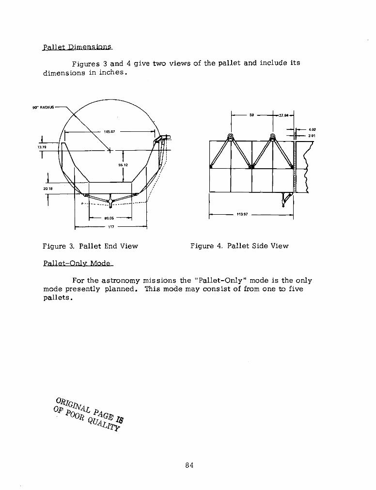
Pallet Dimensions
Figures 3 and 4 give two views of the pallet and include its
dimensions in inches.
0" RADIUS
145.67 59 4.021 O, , 2.0113.78
55.12
20.18
69.05 113.9769.05
117
Figure 3. Pallet End View Figure 4. Pallet Side View
Pallet-Only Mode
For the astronomy missions the "Pallet-Only" mode is the onlymode presently planned. This mode may consist of from one to fivepallets.
W Q i84L
84
THERMAL
S. Ollendorf, GSFC
The thermal problems normally encountered in space are of concernto and are being investigated by GSFC. Some of the areas being studied arelisted below.
SIP S
A thermal cannister enclosing the instruments using the SIPS isbeing designed to allow a favorable, constant operating temperature. Asdesign goals, it will hold instrument bulk temperatures at 20 + 100 C dissi-pating between 20 and 200 Watts of power.
Pallet Mounted Equipment
A thermal analysis has shown that radiation can be trapped betweenthe pallets and Shuttle giving rise to hot spots. Methods are being investi-gated to alleviate this problem.
Experiment Thermal Problems
GSFC is investigating thermal problems on specific experiments thatappear to have unique thermal requirements. Figure 1 shows a typical instru-ment model on a pallet with nodal points.
FIGURE 1. Typical Instrument Model On Pallet With Nodal Points
85
Thermal Model of Spacelab
A thermal model of Spacelab is being prepared by GSFC and resultswill be available at a later time to experimenters. This information shouldenable an investigator to determine the effects of the thermal environmenton his equipment and properly correct for them with heaters, radiators, insul-ations, heat pipes, thermal covers, or whatever may be necessary. Figure 1of Reference 1 is the overall Spacelab thermal model being used for analysis
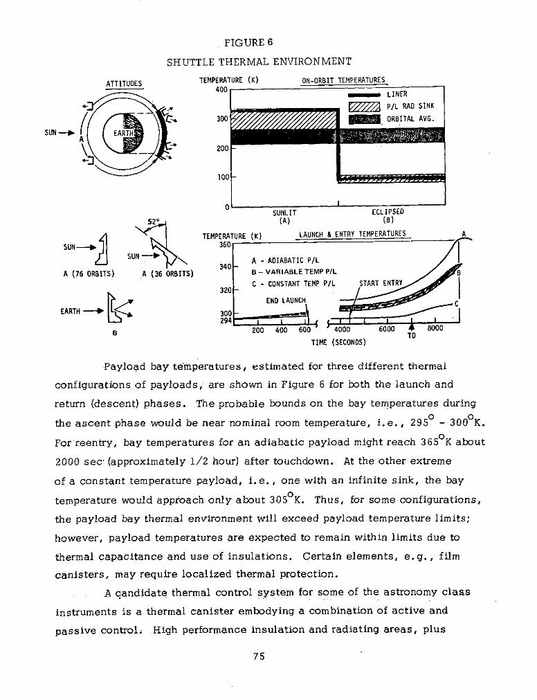
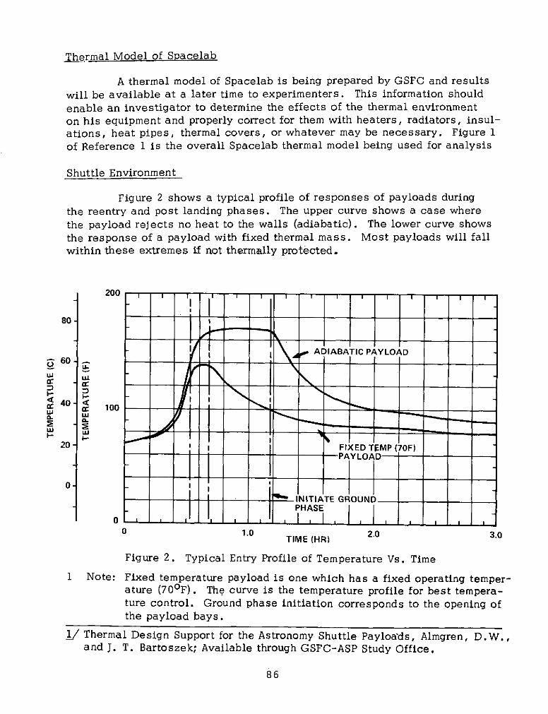
Shuttle Environment
Figure 2 shows a typical profile of responses of payloads duringthe reentry and post landing phases. The upper curve shows a case wherethe payload rejects no heat to the walls (adiabatic). The lower curve showsthe response of a payload with fixed thermal mass. Most payloads will fallwithin these extremes if not thermally protected.
200 ,
80-
"Ae ADIABATIC PAYLOAD60-
S40 U 100
I-.
20 I I FIXED TEMP (70F)- PAYLOAD
0-IINITIATE GROUNDPHASE
0 1.0 TIME (HR) 2.0 3.0
Figure 2. Typical Entry Profile of Temperature Vs. Time
1 Note: Fixed temperature payload is one which has a fixed operating temper-ature (70 0 F). The curve is the temperature profile for best tempera-ture control. Ground phase initiation corresponds to the opening ofthe payload bays.
1/ Thermal Design Support for the Astronomy Shuttle Payloads, Almgren, D.W.,and J. T. Bartoszek; Available through GSFC-ASP Study Office.
86
TEST, EVALUATION AND INTEGRATION
R. Heuser, GSFC
The test and evaluation facilities for the astronomy payloads willbe available at GSFC. An experimenter should be able to coordinate histests with GSFC's Test and Evaluation (T&E) Division personnel to assurethat insofar as possible, the optimum series of tests are defined to assurereliable and productive operation of the payload in-orbit.
Information Required From Experimenters
Generally, experimenters must provide adequate information to forma baseline or criterion against which the results of functional and environ-mental tests can be compared. The purpose of the test may be either tomeasure a characteristic or to evaluate performance. The detailed informationrequired of the experimenter will vary depending on the purpose of the test andthe nature of the experiment. The actual tests to be performed will be decidedon a case by case basis. However, a more detailed philosophy/plan will beavailable in mid-1975.
Tests
Listed below are tests that may be performed at GSFC.
* Initial Magnetic Field * Temperature and Humidity* Leak Detection . Vibration* Electrical Performance * Acoustic Noise* Pyrotecnic Performance * Shocke Physical Measurements * Structural Loads
(Weight, Center of • Thermal Vacuumgravity, Moments of 0 Antenna PatternInertia) * EMI
The user will supply payload-peculiar or unique hardware whichmay include bench test equipment and the personnel for its operation.
Not all of the tests listed may be required. However, because otherexperiments and man's safety are involved, stricter requirements will beplaced on Shuttle payloads then on sounding rocket payloads. An experimentermay be able to demonstrate by analysis, with tighter requirement restraints,that his equipment does not require certain tests.
87
Integration
There are four levels or phases of integration. The first two levels(Levels IV, III) are performed at GSFC while the last two (Levels II, I) areperformed at the laun'ch site. The four levels are listed in Table I.
Table 1Integration Levels for a Spacelab Payload
Level Location Activity
IV GSFC Install Instruments/SupportEquipment on Pallet Segments
III GSFC Experiment Checkout & IntegrationII Launch Site Spacelab IntegrationI Launch Site Orbiter - Cargo Integration
From initiation of Level IV through launch is approximately 22 weeks.
This process is being reviewed from the point of view of the smallpayloads experimenter. Hopefully, ways will be found to reduce the leadtime, minimize the time invested by the experimenter, and to make thepayload accessible up to a few days before launch.
Note: The integration levels, the activities and locations are under review andare subject to change.
88
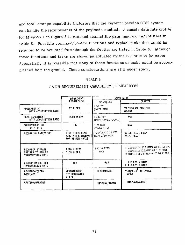
COMMAND AND DATA MANAGEMENT
H. McCain, GSFC
General
The Command and Data Management System (CDMS) provides avariety of services to the Spacelab payload by means of a dedicated dataprocessor, data bus and interfacing units. These services include dataacquisition, monitoring, formatting, processing, displaying, caution andwarning, recording and transmission in addition to providing command andcontrol capability for the Spacelab payloads. An additional set of identicalequipment provides the same services to the Spacelab subsystems.
Figure 1 illustrates the assemblies comprising the CDMS withrespect to experiments. Experiment outputs including status and scientificdata are sampled by Remote Acquisitidn Units '(RAU), converted from analogto digital form and transferred to the experiment-dedicated computer by theinput/output (I/O) controller.
VB/OeE
I / I '/ I
S I G' AMvx
-JI IGIO oi
Figure 1. Assemblies Comprising CDMS
Note: GSFC is studying the use of NIM/CAMAC with power requirements andreliability suitable for Spacelab use.
89
RAU
The RAU can acquire both analog and digital data. The analog por-tion converts the signals to 8 bit resolution digital. The 32 high level inputshave a range from 0 to 5.12V while the 32 low level inputs range from 0 to+256mV. Maximum sampling frequency is 100 Hz. The inputs are single-endedwith 10M&2 impedence.
The 60 digital inputs have Transistor-Tranisitor Logic (TTL) levels.The average data rate is 100 Kbps with a maximum rate of 1 Mbps for 1 msec.
High Data Rate Inputs
There are both analog and digital high frequency data inputs. Bothare 75 ohm.impedance and both feed into a high rate multiplexer. The analoginput has bandwidth of 6 MHz. This information may go either to a 5 MHzrecorder or to the downlink transmission. The digital rate is up to 50 Mbpswith biphase level coding. This information can either go directly to thedownlink at 50 Mbps or stored on tape at 30 Mbps.
TV Signals
TV signals generated by experiment-supplied cameras can be ac-quired by the Spacelab closed-circuit TV system. There is one input pro-vided in each rack segment and on each pallet. The signal can be monitoredat the Orbiter crew station or the operator console on the TV monitors or itcan be transmitted by the Orbiter RF equipment to ground. For non-directtransmissions times the video signal can be recorded.
Data Processing
The CDMS provides a dedicated on-board computer for processing data.which has been acquired by the experiment data bus system. The processingoutputs are displayed on cathode ray tubes (CRT) and transmitted and/ordelivered back to the experiments depending on the mission requirements. Thecomputer facilities allow general processing, such as checkout, sequencingand control of experiments, data reduction, filtering, averaging, histograms,computing, etc. Application software is supplied by the experimenter.
Computer
Table 1 summarizes the characteristics and capabilities of the Spacelabcomputer.
90
Table 1. Computer Characteristics and Capabilities
Formats Floating point (32 bits = 24 + *)Add: 9.0 p sec minimum
Operands: 16,32 and 24+8 (float- Add: 9.0 sec minimum17.1 p sec maximum
28.8 psec maximumMicro-programmed control unit Digital Input/Output
Control memory capacity: Data exchange with peripherals may be1st level: 256 40-bit words serial or parallel, depending on either2nd level: 32 40-bit words of two modes of operation: programmed
(controlled by the program) and channel(independent of the arithmetical unit).
100 instructions including: Data exchange takes the following times:* Single-word (16 bits) and double- Serial
word (32 bits) call and store30.9 p sec in the programmed mode
* Fixed-point arithmetical operations 32.1 p sec in the channel mode, andon 16 and 32 bits, and floating- at a maximum frequency of 31 Kpoint arithmetical operations on words/sec in the locked channel mode32 bits (24 + 8) Parallel
* Logic and comparison operations 4.0 p sec in the programmed mode" Shift operations 1. 8 P sec in the channel mode, and
a maximum frequency of 555K 16-bit* Fixed-to-floating and floating-to - words/sec in the locked channel mode
fixed conversionsThe maximum number of addressable chan-
* Conditional and unconditional jumps nels is:
Addressing Modes 496 on the serial bus
Immediate,direct, indirect, relative to a 2,048 on the parallel busbase, indexed,relative to program MemorycounterNumber of Addressable Registers * Type: 18 mil ferrite cores, 3-D,
3 wire configuration20 by micro-instructions, of which 12
* Capacity: 39 K 16-bit words for thecan also be addressed by instructions basic version, extendibleComputing Speed to 64 K 16-bit words in 8K
During ascent, the POCC would be in a monitor and advisory posture.
On-orbit, the POCC can provide experiment data for the evaluation and controlof the payload. The POCC requires real-time telemetry data and commanduplink to effect evaluation and operation of the payload.
During de-orbit, the POCC will serve to assure proper power downand de-activation of the Spacelab equipment. During actual descent theequipment is assumed to be inactive and the POCC should not require anyinputs during this time.
Additional n-Qrbit Capabilitii
The POCC can provide the following functions and capabilities:
* Decommutate, evaluate, and display payload housekeeping data.
* Provide payload operations control via a real-time commandlink from the POCC.
* Process quick-look experiment sensor data and display for experi-ment analysis and operations planning.
* Provide computational capability for payload operations planningand experiment operations control.
* Provide payload attitude determination and control by interfaceswith external computer systems or with Shuttle Mission ControlCenter.
* Coordinate with Shuttle MCC and payload specialist for Shuttleand Spacelab payload operations.
* Interface with orbit determination systems to provide orbitaldata for payload operations.
Payload Operations System Overview
Figure 1 illustrates the information and communication paths betweenthe Shuttle, free flyers, tracking stations, and operations centers, includingPOCC, for payload operations.
93
CONCLUSIONS
D. Leckrone, GSFC
The Spacelab Astronomy Small Payloads Workshop provided a useful
medium of interchange between a substantial group of potential Spacelab
users and the engineers responsible for the development of support sub-
systems required to accomodate their instruments. A major goal of the
Astronomy Spacelab Payloads study is to provide a benign environment
with realtively simple interfaces to which sounding rocket and balloon
class payloads of the sort that now exist may be adapted at low cost.
The theme of interface simplicity pervaded the Workshop discussion.
If Spacelab is to provide an acceptable extension of our current sounding
rocket capability, an experimenter must be able to easily integrate and
de-integrate his payload, have access to it at specified times during
the integration process, and operate it (or even have it fail) without
interfering with other payloads. He should be able to simulate and
verify payload operations at his home institution. The current philosophy
of the sounding rocket program for payload accomodation should be followed
in the Spacelab program if scientific viability and instrument costs per
observing second are to be maintained at an attractive level.
A major subsystem r1xquirement is a 3- axis pointing platform with
star trackers and a rate integrating gyro system available as part of the
subsystem. The Small Instrument Pointing System (SIPS) concept, including
thermal cannisters, is attractive with respect to its interfacing simplicity
and to its possible commonality with solar physics instrumentation. The use
of SIPS for UV-Optical Astronomy will require roll stabilization, accomodation
of side-looking instruments (impacting both the fineness of roll stabilization
and thermal cannister design), raster scanning, capability for payload evacuation
or dry N2 purge, and the accomodation of cryogenic dewars. In addition to
venting provisions, the latter will require accessibility for cryogen top-off
within eight hours of launch. The currently envisioned SIPS is somewhat over
designed for many astronomy payloads and one might consider a smaller
pointing system for 100-150 Kg payloads with stability requirements of
I, 0 arcsec. Alternatively one might mount more than one small instrument in
a single thermal cannister. The possibility of deploying small payloads with
current Aerobee- pointing controls andretrieving them after use should be
considered.
95
At present an overall concept for command and data handling has not
been firmly established. Problems of concern are the integration and
verification of software while maintaining maximum experimenter independence
and self-sufficiency. Also, the relative roles of on-board payload specialists
and a ground control center need to be defined. Two extreme positions with
respect to the payload specialist role were expressed at the Workshop. On the
one hand, command and data access to instruments through remote acquisition
units (RAU's), coupled with a nearly full-time telemetry capability through
TDRS might obviate the need for a payload specialist. On the other hand,
observers with relatively simple instrument control and data requirements,
who seek maximum interfacing simplicity, should not be required to interact
with a very complex ground control center. Many participants envisioned a
payload specialist performing simple operational tasks, such as power on/off
collimation checks, command sequence initiation, manual film advance,
performance monitoring, etc. Since it will usually not be possible to fly
one payload specialist for each instrument, one will have to decide if he
is willing to have his instrument operated by a payload specialist (an astronomer)
who is not intimatelyfamiliar with it.
Other problems of concern to Workshop participants include the following:
0 difficulties in using long light path instruments because of large
scale payload bay thermal flexures and mutual interference with
other instruments
0 magnetic isolation requirements for electrographs and image intensifiers
* power requirements and vibration sensitivity of standardized electronics
modules (NIMS, CAMACS)
0 sky brightness and large column densities of light atoms and molecules
introduced by orbiter vernier control-system exhaust
* protection of film from thermal "backsoaking" after re-entry
0 the potential cost impact of NASA's testing and documentation requirements
@ frequency of flight opportunities and choice of observing season to com-
plete finite survey programs; total number of flight "slots" available
per year.
Typical lead times for the initial development or adaptation of Spacelab
rocket-class payloads range from two to three years. Therefore, NASA should
begin to make payload development funds available for the initial orbiter
96
test filghts and early Spacelab missions in 1976. To continue the
involvement of the scientific community in support subsystems development,Goddard Space Flight Center will regularly conduct Small Payloads Workshops
and will actively encourage dialogues between individual experimenters and
the engineering group leaders involved in the ASP study. The illustrative
payloads discussed at the first Workshop will be utilized for on-going ASP