106
Field Automation Systems Loose-leaf version: Part Number D301127X012 Bound version: Contact FAS FLOBOSS™ 553 FLOW MANAGER Instruction Manual Form A6073 June 1999 (2 nd Edition)

Field Automation Systems
Loose-leaf version: Part Number D301127X012Bound version: Contact FAS
FLOBOSS™ 553 FLOW MANAGER
Instruction Manual
Form A6073June 1999 (2nd Edition)

FloBoss 553 Instruction Manual
ii Rev 1/00
Revision Tracking Sheet
June 1999, 2nd Edition
This manual may be revised periodically to incorporate new or updated information. The date revisionlevel of each page is indicated at the bottom of the page opposite the page number. A major change inthe content of the manual also changes the date of the manual which appears on the front cover. Listedbelow is the date revision level of each page.
Page Revision
1-20 and 1-21 1/002-15 1/002-29 1/00All others 6/99
Note: This 2nd Edition adds information about changing the default sleep mode activiation values.
Fisher Controls International, Inc. 1999-2000. All rights reserved.
Printed in the U.S.A.
While this information is presented in good faith and believed to be accurate, Fisher Controls does not guarantee satisfactory results fromreliance upon such information. Nothing contained herein is to be construed as a warranty or guarantee, express or implied, regarding theperformance, merchantability, fitness or any other matter with respect to the products, nor as a recommendation to use any product orprocess in conflict with any patent. Fisher Controls reserves the right, without notice, to alter or improve the designs or specifications of theproducts described herein.

FloBoss 553 Instruction Manual
Rev 6/99 iii
Table of Contents
SECTION 1 — GENERAL INFORMATION .......................................................... 1-1
1.1 Manual Overview........................................................................................................................ 1-1
1.2 Section Contents.......................................................................................................................... 1-2
1.3 Additional Information................................................................................................................ 1-2
1.4 Product Overview........................................................................................................................ 1-3
1.5 Installation Requirements ............................................................................................................ 1-8
1.6 Mounting....................................................................................................................................1-13
1.7 Power Consumption Calculation.................................................................................................1-15
1.8 Startup and Operation.................................................................................................................1-20
SECTION 2 — USING THE FLOBOSS 553 ............................................................ 2-1
2.1 Scope.......................................................................................................................................... 2-1
2.2 Section Contents.......................................................................................................................... 2-1
2.3 Product Functions........................................................................................................................ 2-3
2.4 Product Electronics...................................................................................................................... 2-9
2.5 Connecting the FloBoss to Wiring..............................................................................................2-16
2.6 Calibration .................................................................................................................................2-28
2.7 Troubleshooting and Repair........................................................................................................2-29
2.8 Specifications .............................................................................................................................2-35
SECTION 3 — DUAL-VARIABLE SENSOR.......................................................... 3-1
3.1 Scope.......................................................................................................................................... 3-1
3.2 Section Contents.......................................................................................................................... 3-1
3.3 Description.................................................................................................................................. 3-1
3.4 Process Connections.................................................................................................................... 3-2
3.5 DVS Wiring ................................................................................................................................ 3-2
3.6 Configuration .............................................................................................................................. 3-3
3.7 Calibration .................................................................................................................................. 3-5
3.8 Specifications .............................................................................................................................3-13

FloBoss 553 Instruction Manual
Table of Contents (Continued)
iv Rev 6/99
SECTION 4 — COMMUNICATIONS CARDS....................................................... 4-1
4.1 Scope.......................................................................................................................................... 4-1
4.2 Section Contents.......................................................................................................................... 4-1
4.3 Product Descriptions ................................................................................................................... 4-1
4.4 Initial Installation and Setup ........................................................................................................ 4-5
4.5 Connecting Communications Cards to Wiring ............................................................................. 4-7
4.6 Troubleshooting and Repair......................................................................................................... 4-8
4.7 Communication Cards Specifications .........................................................................................4-10
APPENDIX A — LOOP SCHEMATIC....................................................................A-1
A.1 Scope..........................................................................................................................................A-1
A.2 Loop Schematic drawings............................................................................................................A-1
GLOSSARY OF TERMS.......................................................................................... G-1
TOPICAL INDEX .......................................................................................................I-1

FloBoss 553 Instruction Manual
Rev 6/99 1-1
SECTION 1 — GENERAL INFORMATION
1.1 MANUAL OVERVIEW
This manual describes the FloBoss 553 Flow Manager, part of the family of FloBoss 500™ flowcomputers manufactured by Fisher Controls. Included in this manual are the following sections:
♦ Table of Contents Table of Contents♦ Section 1 General Information♦ Section 2 Using the FloBoss 553♦ Section 3 Dual-Variable Sensor♦ Section 4 Communications Cards♦ Appendix A IS Loop Schematic♦ Glossary Glossary of Terms♦ Index Topical Index
Table of Contents lists each section and information contained in that section of the document.
Section 1 describes this manual and mentions related manuals. This section also provides a summaryof the FloBoss hardware, installation requirements, mounting the FloBoss, and power requirements.
Section 2 provides information and specifications concerning the use of the FloBoss. Topics coveredinclude the Main Electronics Board, wiring, processes, and troubleshooting. The Main Electronics Boardprovides the flow sensor input channel, one built-in discrete output channel, a Resistance TemperatureDetector (RTD) input, an operator interface port, and a host communications port.
Section 3 describes the Dual-Variable Sensor (DVS) included with the FloBoss 553 for sensing static (line)pressure and differential pressure across an orifice.
Section 4 provides information and specifications for the optional communications cards.
Appendix A shows the intrinsic safety Loop Schematic as approved for the FloBoss 553.
Glossary of Terms defines terms used in Fisher Control’s documentation.
Topical Index alphabetically lists the items contained in this manual, including their page numbers.

FloBoss 553 Instruction Manual
1-2 Rev 6/99
1.2 SECTION CONTENTS
This section contains the following information:
Information Section Page NumberManual Overview 1.1 1-1Section Contents 1.2 1-2Additional Information 1.3 1-2Product Overview 1.4 1-3
Options 1.4.2 1-7Installation Requirements 1.5 1-8
Environmental Requirements 1.5.1 1-8Site Requirements 1.5.2 1-9Compliance with Hazardous Area Standards 1.5.3 1-10Power Installation Requirements 1.5.4 1-10Grounding Installation Requirements 1.5.5 1-11I/O Wiring Requirements 1.5.6 1-12
Mounting 1.6 1-13Mounting the FloBoss 1.6.1 1-13
Power Consumption Calculation 1.7 1-15Determining I/O Channel Power Consumption 1.7.1 1-15Totaling Power Requirements 1.7.2 1-16Solar Powered Installations 1.7.3 1-17Batteries 1.7.4 1-19
Startup and Operation 1.8 1-20Startup 1.8.1 1-20Operation 1.8.2 1-21
1.3 ADDITIONAL INFORMATION
The following manuals may be used to acquire additional information not found in this manual:
& Type RL101 ROCLINK Configuration Software User Manual – Part Number D301101X012
& Function Sequence Table (FST) User Manual – Part Number D301058X012
& ROC/FloBoss Accessories Instruction Manual – Part Number D301061X012

FloBoss 553 Instruction Manual
Rev 6/99 1-3
1.4 PRODUCT OVERVIEW
The FloBoss 553 is a 32-bit microprocessor-based Electronic Flow Measurement (EFM) computer thatprovides functions required for measuring the differential pressure, static pressure, and the temperatureat a single meter run. From these, the FloBoss computes gas flow for both volume and energy. TheFloBoss provides on-site functionality and supports remote monitoring, measurement, data archival,communications, and control in Class I, Division 1 locations (which may contain continuousconcentrations of flammable gas). The FloBoss design allows you to configure specific applicationsincluding those requiring gas flow calculations, data archival, remote communications, and logic andsequencing control using a Function Sequence Table (FST).
The FloBoss 553 provides the following standard components and features:
♦ Weather-tight, corrosion-resistant enclosure (NEMA 4X).♦ Main Electronic Board.
♦ Built-in Liquid Crystal Display (LCD) with two-line alphanumeric viewing.♦ A 32-bit microprocessor, 512K of flash ROM, and 512K of static memory storage.
♦ Built-in Discrete Output (DO) for sampler or odorizer control.♦ Built-in Dual-Variable Sensor (DVS) for sensing differential and static pressure.♦ Built-in Resistance Temperature Detector (RTD) input.
♦ Operator interface (LOI) port (for non-hazardous areas only).♦ Host communications port for optional communications card.
♦ Applications firmware.
Physically, the FloBoss consists of a printed-circuit Main Electronics Board and a display housed in acompact, weather-tight case. The FloBoss is packaged in a NEMA 4X windowed enclosure that canmount on a wall, a pipestand, or directly to the metering pipe. Refer to Figure 1-1.
The plastic enclosure protects the electronics from physical damage and corrosive environments. Theenclosure has a hinged and gasketed door secured by a lockable hasp. The enclosure has mountingflanges that allow it to be fastened to a wall or panel, or mounted on a pipestand. In addition, it can bedirect-mounted, such as on an integral orifice assembly. The internal structural metal is made from alow-copper aluminum alloy. All exposed metal is stainless steel.
The enclosure is fabricated from fiberglass-reinforced plastic. Enclosure external dimensions,including mounting flanges and the Dual-Variable Sensor (DVS), are approximately 16.75 inches highby 10.38 inches wide by 6.69 inches deep (425 mm by 264 mm by 170 mm). The DVS is factory-mounted to the bottom of the enclosure. Refer to Figure 1-3 on page 1-14 for further dimensionaldetails.

FloBoss 553 Instruction Manual
1-4 Rev 6/99
DOC0334P
SC
ALE
IS .5
Figure 1-1. FloBoss 553 Flow Manager
The Main Electronics Board, displayed in Figure 1-2, mounts on a backplate under a black-anodizedaluminum cover. The dimensions of the board are approximately 5 by 7.5 inches. The majority of thecomponents are surface-mounted, with only the top side of the board used for components. The MainElectronics Board provides built-in I/O capabilities, an LCD display, and provisions for an optionalcommunications card. The main electronics board is factory-mounted inside the housing, whichprovides protection for the electronics. For more information on the Main Electronics Board, refer toSection 2.
The built-in Liquid Crystal Display (LCD) provides the ability to look at data and configurationparameters while on site without using the local operator interface (LOI) and a personal computer. TheLCD display is factory-mounted directly to the Main Electronics Board and visible through the windowon the enclosure door. Through this display, you can view information (defined by configuration)stored in the FloBoss. Up to 16 items can be defined for display. The display automatically cyclesthrough the configured list of items, displaying a new value approximately every three seconds.
Mounting Flange
OperatorInterface
Port
Coupler
Display
DVS

FloBoss 553 Instruction Manual
Rev 6/99 1-5
A Motorola 32-bit CMOS microprocessor runs at 14.7 MHz and has low-power operating modes,including inactivity and low battery conditions. The FloBoss comes standard with 512K of built-in,supercapacitor-backed static random access memory (SRAM) for storing data and history. The FloBossalso has 512K of programmable read-only memory (flash ROM) for storing operating system firmware,applications firmware, and configuration parameters.
The built-in inputs and outputs (I/O) consist of a port for a Dual-Variable Sensor (DVS), a 4-wireResistance Temperature Detector (RTD) input interface, and a discrete output (DO). Diagnostic inputsare dedicated to monitoring input voltage and enclosure temperature. Connectors located on the MainElectronics Board provide terminations for input power, an RTD input, a discrete output (DO), Dual-Variable Sensor (P/DP), and operator interface (LOI) communications. Refer to Figure 1-2.
The built-in discrete output (DO) is capable of controlling a sampler or odorizer. The DO may beused as a Timed Duration Output (TDO).
The Dual-Variable Sensor (DVS) measures differential pressure and absolute or gauge (static)pressure by converting the applied pressure to electrical signals and making the readings available tothe Main Electronics Board. The sensor housing screws into a flanged adapter, which in turn mountswith four bolts to the bottom of the enclosure. The DVS cable plugs directly into the Main ElectronicsBoard at the P/DP connector. For more information on the DVS, refer to Section 3.
An RTD temperature probe typically mounts in a thermowell on the metering pipe. RTD wires shouldbe protected either by a metal sheath or conduit connected to a liquid-tight conduit fitting on the bottomof the FloBoss enclosure. The RTD wires connect directly to the four-terminal RTD connector on theMain Electronics Board inside the enclosure.
The operator interface (LOI) port , located on the bottom left-hand side of the enclosure (refer toFigure 1-1), provides for a local link between the FloBoss and a personal computer through an OperatorInterface Cable. With the personal computer running the ROCLINK Configuration Software, you canconfigure the functionality of the FloBoss and monitor its operation. User-level security can be enabledor disabled for the LOI port.
WARNING
Do not use the LOI port in a hazardous location (Class I, Division 1 or 2). For aFloBoss 553 in a C1D1 area, you may use the Laptop Computer connectors wiredthrough an intrinsic safety barrier as shown in the Loop Schematic (Appendix A).
The host communications port (located at COM1) is available for use with an optional communica-tions card to permit serial communication protocols. User level security can be enabled or disabled forthe host communications port. Refer to Section 4 for details on communication cards.
The I/O parameters, DVS inputs, flow calculations, security, and FST programmability are configuredand accessed using the ROCLINK Configuration Software. Refer to the ROCLINK ConfigurationSoftware User Manual for details concerning software capabilities.

FloBoss 553 Instruction Manual
1-6 Rev 1/00
NORMRST
J1
60
P3
PT2 PT3
P8
MV1
P10
PT1
P5
U6
U9
CR6
FL1
P11
CR9
U7
CR7
U12
U11
MV2
U8
R1
U2
P1
DOC0331A
C3
Figure 1-2. Main Electronics Board
ResetJumper
LCD
Comm CardMatingConnector
SuperCapacitor"Battery"
Board PowerConnector
Built-in I/OWiring
Integral SensorConnector
FlashMemoryChip
DOC0380A

FloBoss 553 Instruction Manual
Rev 6/99 1-7
1.4.1 Firmware
The Version 2.x firmware , contained in flash ROM on the electronics board, determines much of thefunctionality of the FloBoss, such as:
♦ Memory logging of 240 alarms and 240 events.
♦ Archival of data for up to 15 history points for up to 35 days.♦ American Gas Association (AGA) flow calculations for a single meter run.♦ Logic and sequencing control by means of a user-defined Function Sequence Table (FST).
♦ Communications based on either Modbus protocol or ROC protocol.♦ User-level security.
Refer to Section 2.3 for more information about the functionality provided by the firmware.
1.4.2 Options and Accessories
The FloBoss supports the following options and accessories:
♦ Communications Cards for host communications.
♦ Local Operator Interface (LOI) cable.
Two plug-in communication cards are available for the FloBoss installation. The communicationcards provide an interface for the host communications port. These cards permit serial communicationprotocols. One of the following card types can be accommodated:
♦ EIA-232 (RS-232) for asynchronous serial communications.♦ EIA-485 (RS-485) for asynchronous serial communications.
Stand-offs on the Main Electronics Board allow the optional communications cards to be added easily.Refer to Section 4 for more information.
The local operator interface (LOI) port, which is approved for use in non-hazardous areas only,provides for a direct, local link using an Operator Interface Cable between the FloBoss and a personalcomputer. With the personal computer running the ROCLINK Configuration Software, you canconfigure the functionality of the FloBoss and monitor its operation. The Operator Interface Cable isavailable as an accessory from Fisher.
WARNING
Do not use the LOI port in a hazardous location (Class I, Division 1 or 2). For aFloBoss 553 in a C1D1 area, you may use the Laptop Computer connectors wiredthrough an intrinsic safety barrier as shown in the Loop Schematic (Appendix A).

FloBoss 553 Instruction Manual
1-8 Rev 6/99
The FloBoss is powered by a 12-volt dc power supply, typically a solar panel and battery combination.Refer to Section 2, Connecting Power Wiring.
1.5 INSTALLATION REQUIREMENTS
This section provides generalized guidelines for successful installation and operation of the FloBoss.Planning helps to ensure a smooth installation. Be sure to consider location, ground conditions,climate, and site accessibility as well as the suitability of the FloBoss application while planning aninstallation.
The versatility of the FloBoss allows it to be used in many types of installations. For additionalinformation concerning a specific installation, contact your Fisher Representative. For detailed wiringinformation, refer to Section 2.
The Installation Requirements section includes:
♦ Environmental Requirements♦ Site Requirements
♦ Compliance with Hazardous Area Standards♦ Power Installation Requirements
♦ Grounding Installation Requirements♦ I/O Wiring Requirements
NOTE
The FloBoss has been tested and found to comply with the limits for a Class Adigital device, pursuant to part 15 of the FCC Rules. These limits are designed toprovide reasonable protection against harmful interference when the equipment isoperated in a commercial environment. This equipment generates, uses, and canradiate radio frequency energy. If not installed and used in accordance with thisinstruction manual, the FloBoss may cause harmful interference to radio communi-cations. Operation of the equipment in a residential area is likely to cause harmfulinterference, in which case you will be required to correct the interference at yourown expense.
1.5.1 Environmental Requirements
The FloBoss enclosure is classified as a CSA Type 4X (NEMA 4X equivalent) enclosure. Thisprovides the protection required to keep the units operating under a variety of weather conditions.

FloBoss 553 Instruction Manual
Rev 6/99 1-9
The FloBoss is designed to operate over a -40 to 75° C (-40 to 167° F) temperature range. The LCDtemperature range is -25 to 70° C (-13 to 158° F). When mounting the unit, be aware of externaldevices that could have an effect on the operating temperature. Operation beyond the recommendedtemperature range can cause errors and erratic performance. Prolonged operation under extremeconditions can result in premature failure of the unit. In extreme climates, it may be necessary tomoderate the temperature in which the unit must operate.
Check the installation for mechanical vibration. Ensure that the levels of vibration do not exceed thosespecified (see Specifications in Section 2).
1.5.2 Site Requirements
Careful consideration in locating the FloBoss on the site can help prevent future operational problems.The following items should be considered when choosing a location:
♦ Local, state, and federal codes often place restrictions on monitoring locations and maydictate site requirements. Examples of these restrictions are fall distance from a meter run,distance from pipe flanges, and hazardous area classifications.
♦ Locate the FloBoss to minimize the length of signal and power wiring.
♦ When providing solar power to FloBoss units, orient solar panels to face due South (notmagnetic South) in the Northern Hemisphere and due North (not magnetic North) in theSouthern Hemisphere. Make sure nothing blocks the sunlight from 9:00 AM to 4:00 PM.
♦ Antennas equipped for radio communications must be located with an unobstructed signalpath. If possible, locate antennas at the highest point on the site and avoid aiming antennasinto storage tanks, buildings, or other tall structures. Allow sufficient overhead clearance toraise the antenna.
♦ To minimize interference with radio communications, locate the FloBoss away fromelectrical noise sources such as engines, electric motors, and utility line transformers.
♦ Locate the FloBoss away from heavy traffic areas to reduce the risk of being damaged byvehicles. However, provide adequate vehicle access to aid in monitoring and maintenance.

FloBoss 553 Instruction Manual
1-10 Rev 6/99
1.5.3 Compliance with Hazardous Area Standards
The FloBoss 550 Series typically has hazardous location approval for Class I, Division 1, Groups C andD exposures. The Class, Division, and Group terms are defined as follows:
Class defines the general nature of the hazardous material in the surrounding atmosphere.
Class I is for locations where flammable gases or vapors may be present in the air inquantities sufficient to produce explosive or ignitable mixtures.
Division defines the probability of hazardous material being present in an ignitable
concentration in the surrounding atmosphere. Since Division 1 locations are presumed to behazardous, all electrical devices must be designed as intrinsically safe, explosion proof, etc.
Group defines the hazardous material in the surrounding atmosphere. Groups C to D are
defined as follows:
♦ Group C - Atmosphere containing ethylene, gases or vapors of equivalent hazards.♦ Group D - Atmosphere containing propane, gases or vapors of equivalent hazards.
For the FloBoss to be approved for hazardous locations, it must be installed according to the NationalElectrical Code (NEC) Article 501.
WARNING
When installing units in a hazardous area, make sure all installation componentsselected are labeled for use in such areas. Installation and maintenance must beperformed only when the area is known to be non-hazardous.
1.5.4 Power Installation Requirements
The typical source of primary power for FloBoss installations is solar power. If line power is used, caremust be taken to route it away from hazardous areas, sensitive monitoring devices, and radioequipment. Local and company codes generally provide guidelines for line power installations.Adhere rigorously to all local and National Electrical Code (NEC) requirements for line powerinstallations.
CAUTION
Power to the FloBoss must be connected only to the terminal block labeled INPUTPOWER (the MCU PWR terminals are intended for factory use). For Class I,Division 1 installations, power must be connected through intrinsic safety barriersas specified in the Loop Schematic (Appendix A).

FloBoss 553 Instruction Manual
Rev 6/99 1-11
Refer to Section 1.7, Power Consumption Calculation, on page 1-15 to plan for total powerconsumption of the FloBoss.
1.5.5 Grounding Installation Requirements
CAUTION
Grounding for the FloBoss in Class I, Division 1 installations must be done inaccordance with the Loop Schematic (Appendix A). Note that the Intrinsic Safetyground conductors must be connected to a single earth ground.
Ground wiring requirements for line-powered equipment are governed by the National Electrical Code(NEC). When the equipment uses line power, the grounding system must terminate at the servicedisconnect. All equipment grounding conductors must provide an uninterrupted electrical path to theservice disconnect.
The National Electrical Code Article 250-83 (1993), paragraph c, defines the material andinstallation requirements for grounding electrodes.
The National Electrical Code Article 250-91 (1993), paragraph a, defines the materialrequirements for grounding electrode conductors.
The National Electrical Code Article 250-92 (1993), paragraph a, provides installationrequirements for grounding electrode conductors.
The National Electrical Code Article 250-95 (1993) defines the size requirements for equipmentgrounding conductors.
Proper grounding of the FloBoss helps to reduce the effects of electrical noise on the unit’s operationand protects against voltage transients, such as induced by nearby lightning. Transient protection isbuilt-in to the FloBoss, providing protection for built-in field wiring inputs and outputs. A surgeprotection device installed at the service disconnect on line-powered systems offers lightning and powersurge protection for the installed equipment.
All earth grounds must have an earth to ground rod or grid impedance of 25 ohms or less (1 ohm preferred)as measured with a ground system tester for computer equipment. The grounding conductor should have aresistance of 1 ohm or less between the FloBoss case ground lug and the earth ground rod or grid.
The grounding installation method for the FloBoss depends on whether the pipeline has cathodicprotection. On pipelines with cathodic protection, the FloBoss must be electrically isolated from thepipeline. Electrical isolation can be accomplished by using insulating flanges upstream and downstreamon the meter run. In this case, the FloBoss could be flange mounted or saddle-clamp mounted directly onthe meter run and grounded with a ground rod or grid system.

FloBoss 553 Instruction Manual
1-12 Rev 6/99
On pipelines without cathodic protection, the pipeline itself may provide an adequate earth ground and theFloBoss could mount directly on the meter run. Using a ground system tester, test to make sure thepipeline to earth impedance is less than 25 ohms. If an adequate ground is provided by the pipeline, do notinstall a separate ground rod or grid system. All grounding should terminate at a single point.
If the pipeline to earth impedance is greater than 25 ohms, the FloBoss installation should be electricallyisolated and a ground rod or grid grounding system installed.
Shields for I/O signal wiring used in the FloBoss should be grounded. A ground bar is provided insidethe FloBoss enclosure for terminating shield wires and other connections that require earth ground.Note that shields should be grounded at one end only to prevent ground loops.
A lug on the outside of the FloBoss enclosure is provided to connect the enclosure to earth ground.Note that on the FloBoss 550 series, the ground bar is internally connected to the enclosure ground lug;no further connection between these points is needed.
1.5.6 I/O Wiring Requirements
I/O wiring requirements are site and application dependent. Local, state, or NEC requirements maydetermine I/O wiring installation methods. Direct burial cable, conduit and cable, or overhead cablesare options for I/O wiring installations. Section 2 contains detailed information on connecting I/Owiring to the FloBoss.
The recommended cable for I/O signal wiring is an insulated, shielded, twisted-pair. The twisted pairand the shielding minimize signal errors caused by EMI (electromagnetic interference), RFI (radiofrequency interference), and transients. A ground bar is provided inside the enclosure for terminatingshield wires. Note that cable shields should be grounded at one end only.
The I/O wiring for the FloBoss is connected to terminals on the lower edge of the Main ElectronicsBoard. Refer to Figure 1-2. The terminal designations are printed on the electronics cover.

FloBoss 553 Instruction Manual
Rev 6/99 1-13
1.6 MOUNTING
When choosing an installation site, be sure to check all clearances. For dimensions, refer to Figure 1-3.Provide adequate clearance for the enclosure door to be opened for wiring and service. The door ishinged on the left side. The LCD display should be visible and accessible for the on-site operator.
When using a solar panel (must not be located in the Class I, Division 1 area with the FloBoss), thereshould be adequate clearance, and view of the sun should not be obstructed. Allow adequate clearanceand an obstructed location for antennas when using radios.
The Dual-Variable Sensor (DVS) is factory-mounted directly to the FloBoss enclosure with four bolts.This mounting uses a special coupler to join the threads on the sensor to the four-bolt mounting patternon the bottom of the FloBoss enclosure. See Section 3 for more information.
1.6.1 Mounting the FloBoss
Mounting of the FloBoss can be accomplished using any of the following methods:
♦ Pipe mounted – The enclosure provides top and bottom mounting flanges with holes for2-inch pipe clamps (U-bolts and brackets supplied). The 2-inch pipe can be mounted toanother pipe with a pipe saddle, or it can be cemented into the ground deep enough to supportthe weight and conform to local building codes.
♦ Wall or panel mounted – Fasten to the wall or panel using the mounting flanges on theenclosure. Use 5/16-inch bolts through all four holes. Hole spacing dimensions are given inFigure 1-3.
♦ Integral orifice mounted – Fasten to the pipe using integral orifice mounting equipment andtechniques.
With all mounting methods, the pressure inputs must be piped to the ¼-18 NPT process connections onthe sensor. Refer to Section 3 for more information on piping.
CAUTION
The FloBoss 553 must be mounted vertically with the Dual-Variable Sensor at its base asshown in Figure 1-3.

FloBoss 553 Instruction Manual
1-14 Rev 6/99
DOC0334A
2X .44
16.88
12.50
10.38
2.813.25
6.75
Figure 1-3. Outline and Mounting Dimensions

FloBoss 553 Instruction Manual
Rev 6/99 1-15
1.7 POWER CONSUMPTION CALCULATION
A FloBoss system’s power consumption determines power supply and battery sizing for both line andsolar power. Table 1-1 provides information to assist in determining power requirements. The FloBosshas low power consumption due to a typical duty cycle of 10 to 20% for its microprocessor; the other80 to 90% of the time the microprocessor is shut off, with external wake-up signals reactivating it.
The Power Consumption Calculation section includes:
♦ Determining I/O Channel Power Consumption
♦ Totaling Power Requirements♦ Solar Powered Installations♦ Batteries
1.7.1 Determining I/O Channel Power Consumption
In estimating total I/O power requirements, the “duty cycle” of each I/O channel must be estimated.For example, if a discrete output is active for 15 seconds out of every 60 seconds, the duty cycle is:
Duty Cycle = Active time/(Active time + Inactive time) = 15 sec/60 sec = 0.25
To calculate the total power consumed by an I/O channel, use Table 1-1 and read the minimum (Pmin)and maximum (Pmax) power consumption value from the table for the desired I/O channel. Use thefollowing equation to calculate the power consumption for a channel with the duty cycle taken intoaccount:
Power = (Pmax x Duty Cycle) + [Pmin (1 - Duty Cycle)]
Multiply this value by the Quantity of I/O channels with the same Duty Cycle and enter the calculatedvalue in the Subtotal column. Repeat the procedure for all other I/O channels used.

FloBoss 553 Instruction Manual
1-16 Rev 6/99
Table 1-1. Power Consumption of the FloBoss 553 and Powered Devices
Device Power Consumption(mW) 12V System
Quantity Duty Cycle Subtotal(mW)
Pmin Pmax
Main Electronics Board; includesminimum built-in I/O powerconsumption, RTD, and integralsensor.
400 2000 1 N/A
Built-in Discrete Output (loaddependent with a maximum of 5volts and 25 milliamps).
0 125 1
Serial Communications Card 30 N/A
Total
1.7.2 Totaling Power Requirements
To adequately meet the requirements of the FloBoss system, it is important to determine the total powerconsumption, size of solar panel, and battery backup requirements accordingly. For total FloBosspower consumption, add the device values in Table 1-1. Although Table 1-1 takes into account thepower supplied by the FloBoss to its connected devices, be sure to add the power consumption (in mW)of any other devices used with the FloBoss in the same power system, but not accounted for in the table(such as intrinsic safety barriers).
Convert the total value (in mW) to Watts by dividing it by 1000.
mW / 1000 = Watts
For selecting an adequate power supply, use a safety factor (SF) of 1.25 to account for losses and othervariables not factored into the power consumption calculations. To incorporate the safety factor,multiply the total power consumption (P) by 1.25.
PSF = P x 1.25 = _____ Watts
To convert PSF to current consumption in amps (ISF), divide PSF by the system voltage (V), which is 12-volts.
ISF = PSF / V = _____ Amps

FloBoss 553 Instruction Manual
Rev 6/99 1-17
1.7.3 Solar Powered Installations
Solar power allows installation of the FloBoss in locations where line power is not available. The twoimportant elements in a solar installation are solar panels and the battery. Solar panels and the batterymust be properly sized for the application and geographic location to ensure continuous, reliableoperation. Note that the solar panel and battery must not be located in a Class I, Division 1 area alongwith the FloBoss (see Loop Schematic).
Fisher Controls does not offer solar panels for FloBoss 500-series units. However, a list of acceptablesolar panels is provided below. Refer to the manufacturer’s literature for installation instructions. Thefollowing solar panels are approved by CSA for use in Class I, Division 2 locations.
♦ Solarex MSX-5 5.0 watt♦ Solarex MSX-10 10.0 watt♦ UniSolar US-5 5.0 watt
♦ UniSolar US-10 10.0 watt
The panel must face due South (not magnetic South) in the Northern Hemisphere and due North (notmagnetic North) in the Southern Hemisphere. The panel must also be tilted at an angle from thehorizontal dependent on the latitude to maximize the energy output. The angles for different latitudesare normally included in the solar panel documentation. At most latitudes, the performance can beimproved by less of an angle during the summer and more of an angle during the winter.
As a site may have additional power requirements for radios, repeaters, and other monitoring devices,power supply and converter accessories may be used to minimize the number of separate power sourcesrequired for an installation.
Solar arrays are used to generate electrical power from solar radiation. The size and number of solarpanels required for a particular installation depends on several factors, including the powerconsumption of all devices connected to the solar array and the geographic location of the installation,as explained below.
To determine solar panel output requirements, first determine the solar insolation for your geographicarea. The map in Figure 1-4 shows solar insolation (in hours) for the United States during wintermonths. Your local Fisher Representative can help you find a map detailing your specific geographicarea.
Insolation (from map) = _____ hours
Next, calculate the amount of current required from the solar array per day using the followingequation. ISF is the system current requirement. Refer to Section 1.7.2 on page 1-16.
Iarray = [ISF (amps) × 24 (hrs)]/Insolation (hrs) = _____ amps

FloBoss 553 Instruction Manual
1-18 Rev 6/99
Finally, the number of solar panels can be determined using the following equation:
Number of Panels = Iarray amps/(Ipanel amps/panel) = _____ panels
Figure 1-4. Solar Insolation in Hours for the United States
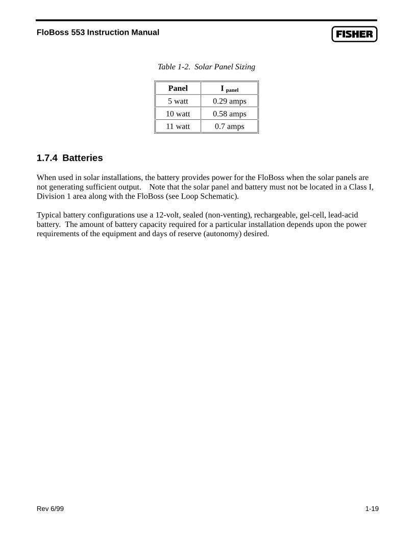
For example, if Iarray equals 0.54 amps, and Ipanel equals 0.29 amps for a 5-watt panel, then the numberof panels required equals 1.86, which would be rounded up to 2 (panels connected in parallel). Alterna-tively, the next larger solar panel can be used, which in this case would be a 10-watt panel. Table 1-2gives Ipanel values for solar panels recommended by Fisher Controls.
NOTE
The “I panel” value varies depending on the type of solar panel installed. Refer to thevendor’s specifications for the solar panel being used.
FloBoss 553 Instruction Manual
Rev 6/99 1-19
Table 1-2. Solar Panel Sizing
Panel I panel
5 watt 0.29 amps
10 watt 0.58 amps
11 watt 0.7 amps
1.7.4 Batteries
When used in solar installations, the battery provides power for the FloBoss when the solar panels arenot generating sufficient output. Note that the solar panel and battery must not be located in a Class I,Division 1 area along with the FloBoss (see Loop Schematic).
Typical battery configurations use a 12-volt, sealed (non-venting), rechargeable, gel-cell, lead-acidbattery. The amount of battery capacity required for a particular installation depends upon the powerrequirements of the equipment and days of reserve (autonomy) desired.
FloBoss 553 Instruction Manual
1-20 Rev 1/00
1.8 STARTUP AND OPERATION
Before starting the FloBoss, perform the following checks to ensure the unit is properly installed.
♦ Make sure the enclosure has a good earth ground connected to the earth ground bus insidethe enclosure.
♦ Check the field wiring for proper installation. Refer to Section 2.♦ Make sure the Input Power has the correct polarity.♦ Make sure the Input Power is fused at the power source.
WARNING
To ensure safe operation, installation and wiring connections must be made asshown in the Loop Schematic of Appendix A. Only the options listed there may beused.
CAUTION
Bonding between conduit connections is not automatic and must be provided as partof the installation.
CAUTION
Power to the FloBoss 550 Series must only be connected to the INPUT POWERconnector, not to the MCU PWR connector. Ensure that the voltage does not exceed16 Vdc, or damage to the FloBoss electronics may result.
CAUTION
It is important to check the input power polarity before turning on the power.Incorrect polarity can damage the FloBoss electronics.
1.8.1 Startup
After observing the above cautions, apply power to the FloBoss. After the FloBoss completes start-updiagnostics (RAM and other internal checks), the LCD displays the date and time to indicate that theFloBoss completed a valid reset sequence. If the LCD does not come on, refer to the Troubleshootingand Repair paragraphs in Section 2 for possible causes.
IMPORTANT NOTICE
For the FloBoss 553 to operate properly on a 12-volt system with intrinsic safetybarriers in place, you must change the activation values for the sleep mode to lower
FloBoss 553 Instruction Manual
Rev 1/00 1-21
values as instructed in Section 1.8.2. If you do not change these values, the FloBosswill readily go into a sleep mode and fail to operate normally.
1.8.2 Operation
Once startup is successful, it is necessary to configure the FloBoss to meet the requirements of thenotice above and of the application. The ROCLINK Configuration Software User Manual (FormA6051) details the procedure for configuring the FloBoss and calibrating the I/O. Once the FloBoss isconfigured and calibrated, it can be placed into operation.
WARNING
Local configuration or monitoring of the FloBoss through the LOI port on thebottom of the enclosure must be performed only in an area known to be non-hazardous.
To set the proper sleep mode activation values (see NOTICE above), connect a computer to the LOIport and run the ROCLINK Configuration Software. In the I/O menu, select AI and page (use F3 key)to the screen for Point E1. In this screen make sure alarming is Enabled, and use the Alarmspushbutton to bring up the Alarms dialog box. In this dialog box, change the Low Alarm value to 5.6volts, change the LoLo Alarm value to 5.2 volts, and click OK. These values will allow the FloBoss tooperate with intrinsic safety barriers without unnecessarily going into sleep mode. Save the new valuesin the E1 screen (use F8 key). Also save the new values to permanent memory (in case of a coldrestart) by selecting Flags in the System menu, turning Write to Internal Config Memory to Yes, andsaving (F8 key).
During operation, the FloBoss can be monitored (to view or retrieve current and historical data) eitherlocally or remotely. Local monitoring is accomplished either by viewing the LCD panel detailed inSection 2, or by using ROCLINK on a PC connected through the LOI port. Remote monitoring isperformed through the host port (COM1) of the FloBoss, using either ROCLINK or host software.Refer to the ROCLINK User Manual for more information on monitoring.

FloBoss 553 Instruction Manual
1-22 Rev 6/99
[This page intentionally left blank.]

FloBoss 553 Instruction Manual
Rev 6/99 2-1
SECTION 2 — USING THE FLOBOSS 553
2.1 SCOPE
This section describes the FloBoss™ 553 Flow Manager, focusing on how it works and how to connectits wiring. Topics include:
♦ Product Functions♦ Product Electronics♦ Connecting the FloBoss to Wiring♦ Troubleshooting and Repair♦ Specifications
2.2 SECTION CONTENTS
This section contains the following information:
Information Section Page NumberScope 2.1 2-1Section Contents 2.2 2-1Product Functions 2.3 2-3
Flow Measurement 2.3.1 2-31985 Flow Calculations 2.3.1.1 2-31992 Flow Calculations 2.3.1.2 2-4
History Points 2.3.2 2-6Minute Historical Log 2.3.2.1 2-6Hourly Historical Log 2.3.2.2 2-6Daily Historical Log 2.3.2.3 2-7Alarm Log 2.3.2.4 2-7Event Log 2.3.2.5 2-7
Security 2.3.3 2-8Function Sequence Tables (FST) 2.3.4 2-8Modbus 2.3.5 2-8
Product Electronics 2.4 2-9Main Electronics Board Overview 2.4.1 2-9Microprocessor and Memory 2.4.2 2-9Liquid Crystal Display 2.4.3 2-11Communications Ports 2.4.4 2-11
Operator Interface Port 2.4.4.1 2-11Host Port 2.4.4.2 2-12

FloBoss 553 Instruction Manual
2-2 Rev 6/99
Information Section Page NumberBuilt-In Discrete Output 2.4.5 2-12RTD Input 2.4.6 2-13Diagnostic Inputs 2.4.7 2-13Real-Time Clock 2.4.8 2-13Automatic Self-Tests 2.4.9 2-14
Connecting the FloBoss to Wiring 2.5 2-16Making Wiring Connections 2.5.1 2-17Connecting Ground Wiring 2.5.2 2-19Connecting Power Wiring 2.5.3 2-20RTD Wiring 2.5.4 2-22Discrete Output Wiring 2.5.5 2-24Connecting Communications Wiring 2.5.6 2-25
Operator Interface Port Wiring 2.5.6.1 2-26Host Port Wiring 2.5.6.2 2-27
Dual-Variable Sensor Wiring 2.5.7 2-27Calibration 2.6 2-28Troubleshooting and Repair 2.7 2-29
Backup Procedure Before Removing Power 2.7.1 2-29Resetting the FloBoss 2.7.2 2-30
Warm Start 2.7.2.1 2-30Cold Start 2.7.2.2 2-31Jumper Reset 2.7.2.3 2-32
After Installing Components 2.7.3 2-33Specifications 2.8 2-35

FloBoss 553 Instruction Manual
Rev 6/99 2-3
2.3 PRODUCT FUNCTIONS
This section describes the functions of the FloBoss 553, most of which is determined by its firmware.The features and applications provided by the firmware, which is configured by using the ROCLINKConfiguration Software, are:
♦ 1985 or 1992 AGA flow calculations for an orifice meter.♦ Archival of data for up to 15 history points.
♦ Memory logging of 240 alarms and 240 events.♦ Security with local and remote password protection.
♦ Logic and sequencing control using a user-defined FST program.♦ Modbus Protocol Emulation Program.
2.3.1 Flow Measurement
The primary function of the FloBoss 553 is to measure and calculate the flow of natural gas inaccordance with the 1985 or 1992 American Petroleum Institute (API) and American Gas Association(AGA) standards. The FloBoss performs either 1985 or 1992 AGA calculations, depending on whichwas ordered.
The primary inputs used for the orifice metering flow measurement function are differential pressure,static (line) pressure, and temperature. The differential and static pressure inputs come from the Dual-Variable Sensor. The temperature input comes from an RTD probe. In the FloBoss 553:
♦ Differential pressure is sampled once per second.
♦ Static pressure is sampled once per second.♦ Temperature is sampled and linearized once per second. The RTD is internally re-calibrated for
every 5° C temperature change as sensed by enclosure temperature (diagnostic input E5).
2.3.1.1 1985 Flow Calculations for Orifice Metering
The 1985 flow calculation is in accordance with ANSI/API 2530-85 (AGA Report No. 3 1985), APIChapter 14.2 (AGA Report No. 8 1985), and API Chapter 21.1. The 1985 flow calculation may beconfigured for either Metric or English units.

FloBoss 553 Instruction Manual
2-4 Rev 6/99
Flow Time
The differential pressure stored for each second is compared to the configured low flow cutoff. If thedifferential pressure is less than or equal to the low flow cutoff or the converted static pressure is lessthan or equal to zero, flow is considered to be zero for that second. Flow time for a recalculation periodis defined to be the number of seconds for which the differential pressure exceeded the low flow cutoff.
Input and Extension Calculation
Every second the FloBoss 553 stores the measured input for differential pressure, static pressure, andtemperature and calculates the flow extension (defined as the square root of the absolute upstream staticpressure times the differential pressure).
Flow time averages of the inputs and the flow extension over the configured recalculation period(Integral Multiplier Period) are calculated unless there is no flow for an entire recalculation period. Ifthere is no flow, averages of the inputs are recorded to allow monitoring during no flow periods.
Instantaneous Rate Calculations
The instantaneous value of the flow extension is used with the previous recalculation period’s C´ (CPrime) to compute the instantaneous flow rate. The instantaneous flow rate is used with the volumetricheating value to compute the instantaneous energy rate.
Flow and Energy Accumulation
The averages of the differential and static pressure, temperature, and flow extension are used with theflow time to compute the flow and energy over the recalculation period. The flow and energy are thenaccumulated and stored at the top of every hour. At the configured Contract Hour, the flow and energyare then stored to the Daily Historical Log and zeroed for the start of a new day.
2.3.1.2 1992 Flow Calculations for Orifice Metering
The 1992 flow calculation is in accordance with ANSI/API 2530-92 (AGA Report No. 3 1992), APIChapter 14.2 (AGA Report No. 8 1992 2nd printing 1994), and API Chapter 21.1. The 1992 flowcalculation may be configured for either Metric or English units.

FloBoss 553 Instruction Manual
Rev 6/99 2-5
Flow Time
The differential pressure stored for each second is compared to the configured low flow cutoff. If thedifferential pressure is less than or equal to the low flow cutoff or the converted static pressure is lessthan or equal to zero, flow is considered to be zero for that second. Flow time for a recalculation periodis defined to be the number of seconds for which the differential pressure exceeded the low flow cutoff.
Input and Extension Calculation
Every second the FloBoss 553 stores the measured input for differential pressure, static pressure, andtemperature and calculates the flow extension (defined as the square root of the absolute upstream staticpressure times the differential pressure).
Flow time averages of the inputs and the flow extension over the configured recalculation period arecalculated unless there is no flow for an entire recalculation period. If there is no flow, averages of theinputs are recorded to allow monitoring during no flow periods.
Instantaneous Rate Calculations
The instantaneous value of the flow extension is used with the previous recalculation period’s IntegralMultiplier Value (IMV) to compute the instantaneous flow rate. The IMV is defined as the valueresulting from the calculation of all other factors of the flow rate equation not included in the IntegralValue (IV). The IV is defined as the flow extension. The instantaneous flow rate is used with thevolumetric heating value to compute the instantaneous energy rate.
Flow and Energy Accumulation
The averages of the differential and static pressure, temperature, and flow extension are used with theflow time to compute the flow and energy over the recalculation period. The flow and energy are thenaccumulated and stored at the top of every hour. At the configured Contract Hour, the flow and energyare then stored to the Daily Historical Log and zeroed for the start of a new day.

FloBoss 553 Instruction Manual
2-6 Rev 6/99
2.3.2 History Points
A total of fifteen history points may be accessed in the FloBoss 553. The first eight are pre-configuredfor flow metering history and cannot be changed. For orifice metering, they are as follows:
1. Accumulated Flowing Minutes.2. Averaged Differential Pressure.3. Averaged Static Pressure.4. Averaged Temperature.5. Averaged C´ or Integral Multiplier Value (IMV).6. Averaged Pressure Extension or Integral Value (IV).7. Accumulated Instantaneous Flow.8. Accumulated Instantaneous Energy.
History points 2, 3, 4, and 6 are set up as an Average Archive Type, using one of the followingtechniques:
♦ Flow dependent time-weighted linear averaging.♦ Flow dependent time-weighted formulaic averaging.
♦ Flow-weighted linear averaging.♦ Flow-weighted formulaic averaging.
The remaining seven history points may be configured as desired.
2.3.2.1 Minute Historical Log
The FloBoss has a 60-minute Historical Log for every history point. The Minute Historical Log storesthe last 60 minutes of data from the current minute. Each history point has Minute Historical Logentries unless the history point is configured for FST-controlled logging.
2.3.2.2 Hourly Historical Log
The FloBoss has a total of 840 Hourly Historical Logs available for every history point. The HourlyHistorical Log is also called the Periodic Log. Normally, the Hourly Log is recorded every hour at thetop of the hour. The exceptions are FST Minute and FST Second logging.
The time stamp for periodic logging consists of the month, day, hour, and minute. The exception is forFST Second logging, in which the time stamp consists of the day, hour, minute, and second.

FloBoss 553 Instruction Manual
Rev 6/99 2-7
2.3.2.3 Daily Historical Log
The FloBoss has a total of 35 Daily Historical Logs for every history point. The Daily Log is recordedat the configured Contract Hour every day with a time stamp that is the same as the Hourly Log. Eachhistory point has Daily Historical Log entries unless the history point is configured for FST-controlledlogging.
2.3.2.4 Alarm Log
The Alarm Log contains the change in the state of any alarm signal that has been enabled for alarms.The system Alarm Log has the capacity to maintain and store up to 240 alarms in a “circular” log. TheAlarm Log has information fields which include time and date stamp, alarm clear or set indicator, andeither the Tag name of the point which was alarmed with the current value or a 14-character ASCIIdescription.
In addition to providing functionality for appending new alarms to the log, it allows host packages torequest the index of the most recently logged alarm entry. Alarm Logging is available internally to thesystem, to external host packages, to the FST, and to User C programs. Alarm Logs are not stored tothe flash ROM during the ROCLINK Save Configuration function.
The Alarm Log operates in a circular fashion with new entries overwriting the oldest entry when thebuffer is full. The Alarm Log provides an audit history trail of past operation and changes. The AlarmLog is stored separately to prevent recurring alarms from overwriting configuration audit data.
2.3.2.5 Event Log
The Event Log contains changes to any parameter within the FloBoss made through the protocol. ThisEvent Log also contains other FloBoss events such as power cycles, cold starts, and disk configurationdownloads.
The system Event Log has the capacity to maintain and store up to 240 events in a circular log. TheEvent Log has information fields which include point type, parameter number, time and date stamp,point number if applicable, the operator identification, and either the previous and current parametervalues or a 14-byte detail string in ASCII format.
In addition to providing functionality for appending new events to the log, it allows host packages torequest the index of the most recently logged event entry. Event Logging is available internally to thesystem, to external host packages, and to the FST.

FloBoss 553 Instruction Manual
2-8 Rev 6/99
Event Logs are not stored to flash ROM when the Save Configuration function is issued in theROCLINK Configuration Software. The Event Log operates in a circular fashion with new entriesoverwriting the oldest entry when the buffer is full. The Event Log provides an audit trail history ofpast operation and changes. The Event Log is stored separately to prevent recurring alarms fromoverwriting configuration audit data.
2.3.3 Security
The FloBoss provides for security within the unit. A maximum of 16 log-on identifiers (IDs) may bestored. In order for the unit to communicate, the log-on ID supplied to the ROCLINK ConfigurationSoftware must match one of the IDs stored in the FloBoss. The Operator Interface port (Security onLOI) has security Enabled by default. The host port (Security on COM1) can likewise be configured tohave security protection, but is disabled by default. Refer to the ROCLINK Configuration SoftwareUser Manual concerning security.
2.3.4 Function Sequence Tables (FST)
The FloBoss supports FST user programmability. The FST program can be from 200 to 300 lines ofcode depending upon the FST. The FST code resides in static RAM and is backed up to flash memorywhen the “Save Configuration” function is issued through the ROCLINK Configuration Software. Seethe ROCLINK Configuration Software User Manual and the Function Sequence Table (FST) UserManual (Form A4625).
2.3.5 Modbus
The Modbus Protocol Emulation Program is contained within the FloBoss firmware. The Modbusapplication is designed to allow the FloBoss to emulate the communications protocol used by Modbusdevices. The Modbus communications protocol is fully described in the reference guide entitled“Modicon Modbus Protocol” publication PI-MBUS-300.
Although the Modbus protocol can be either a Master or a Slave device, the FloBoss 553 is the Slavedevice. The Modbus protocol supports two modes of transmission, ASCII and RTU. Both modes oftransmission are supported by the FloBoss 553.

FloBoss 553 Instruction Manual
Rev 6/99 2-9
2.4 PRODUCT ELECTRONICS
This section describes the FloBoss Main Electronics Board, which is also called the MCU board.
2.4.1 Main Electronics Board Overview
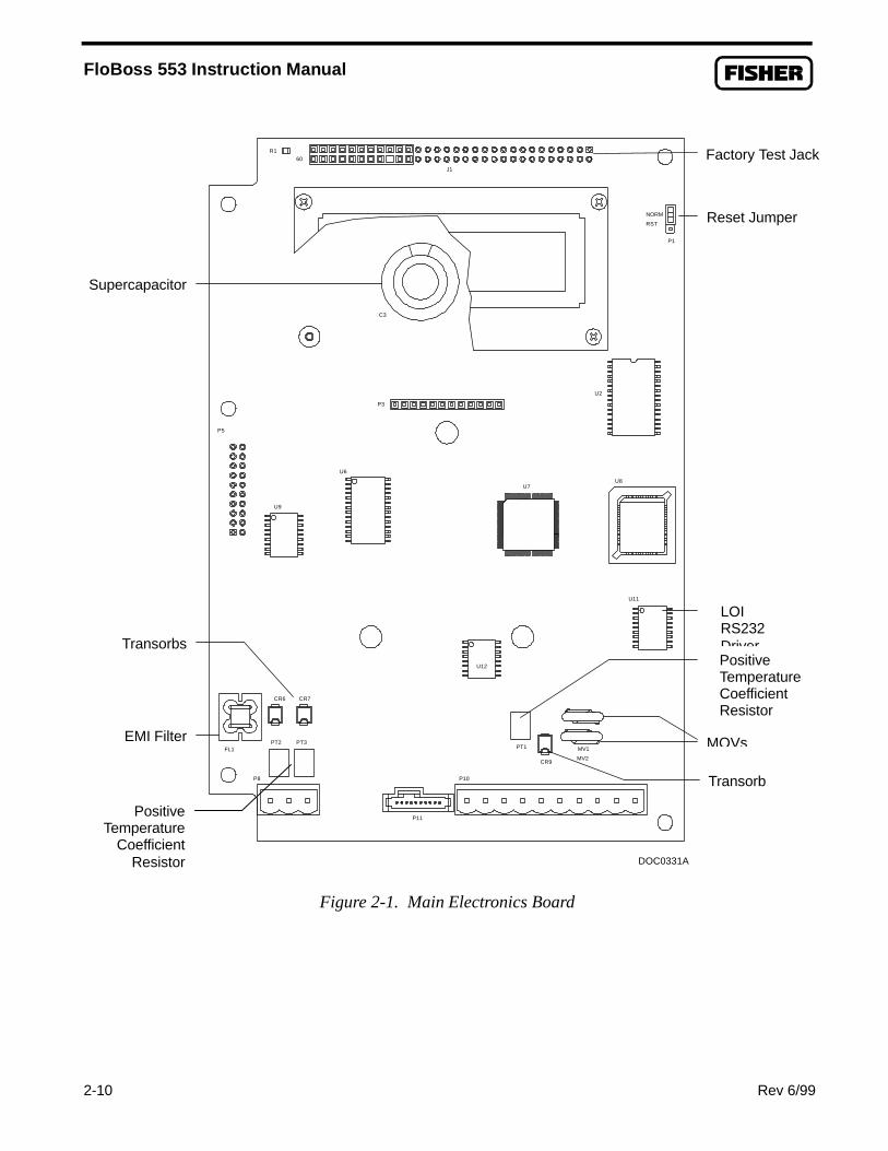
The Main Electronics Board components support the functionality of the FloBoss. Refer toFigure 2-1. The board provides:
♦ 32-bit microprocessor♦ Built-in static RAM
♦ Flash ROM♦ Liquid Crystal Display (LCD) display
♦ Communications card host port (P3)♦ Operator interface port (LOI)♦ Built-in Discrete Output (DO)
♦ Built-in RTD Input (RTD)♦ Board temperature and voltage monitor/diagnostic inputs
♦ Real-time clock and backup power♦ Automatic self-tests
2.4.2 Microprocessor and Memory
The FloBoss derives processing power from a 32-bit microprocessor. The 32-bit CMOSmicroprocessor features dual 32-bit internal data buses and a single 8-bit external data bus. The unitcan address up to four megabytes of memory including high-speed direct memory access.
The Main Electronics Board has 512 Kbytes of static random access memory (SRAM) for storinginterrupt vectors, Function Sequence Tables (FST), alarms, events, and history data.
The Main Electronics Board also has a 512 Kbyte flash memory chip for storing the operating systemfactory code and configuration parameters. Two of the 64 Kbyte blocks are reserved for internal usage.
FloBoss 553 Instruction Manual
2-10 Rev 6/99
NORM
RST
J1
60
P3
PT2 PT3
P8
MV1
P10
PT1
P5
U6
U9
CR6
FL1
P11
CR9
U7
CR7
U12
U11
MV2
U8
R1
U2
P1
DOC0331A
C3
Figure 2-1. Main Electronics Board
Factory Test Jack
Reset Jumper
LOIRS232Driver
MOVs
Transorb
PositiveTemperatureCoefficientResistor
Supercapacitor
PositiveTemperature
CoefficientResistor
Transorbs
EMI Filter

FloBoss 553 Instruction Manual
Rev 6/99 2-11
2.4.3 Liquid Crystal Display
A two-line Liquid Crystal Display (LCD) panel is mounted on the Main Electronics Board. The panelhas automatic contrast adjustment due to temperature sensing and bias adjustment circuitry on the MainElectronics Board.
The LCD panel remains on at all times when the power applied is within the valid operating range. Thepanel cycles its display through a configured list of up to 16 parameter values. The first two displays,which you cannot configure, show values for time and date, operating voltages, and battery condition.The next five displays are configured by the factory to show certain flow parameters, but you maychange their configuration. Refer to the ROCLINK User Manual for details on how to configure thelist of values for the LCD panel.
2.4.4 Communications Ports
The FloBoss provides for two communication ports:
♦ Operator interface port – LOI.♦ Host port for communication to a remote host – COM1.
2.4.4.1 Operator Interface Port – LOI
The Operator Interface port, also called the Local Operator Interface (LOI) port, provides directcommunications between the FloBoss and the serial port of an operator interface device such as an IBMcompatible computer. The interface allows you to access the FloBoss (using the ROCLINKConfiguration Software) for configuration and transfer of stored data. The LOI terminal on the MainElectronics Board provides wiring access to a built-in EIA-232 serial interface and is capable of up to19.2k baud rate. The operator interface port supports only ROC protocol communications. The LOIalso supports the log-on security feature of the FloBoss if the “Security on LOI” is Enabled inROCLINK.
A cannon-type waterproof connector on the bottom of the enclosure provides connection through aprefabricated cable (available from Fisher) for an operator interface device, typically an IBM-compatible personal computer (PC) running the ROCLINK Configuration Software. Inside the FloBossenclosure, the cannon-type connector is wired to three terminals (LOI) on the Main Electronics Board.
WARNING
Do not use the LOI port on the bottom of the FloBoss enclosure in a hazardouslocation (Class I, Division 1 or 2). Instead, use the Laptop Computer connectorsthat are wired through an intrinsic safety barrier as shown in the Loop Schematic(Appendix A).

FloBoss 553 Instruction Manual
2-12 Rev 6/99
2.4.4.2 Host Port – COM1
The host port (also called the COM1 port) is activated by the installation of the optional communica-tions card. The host port is used to monitor or alter the FloBoss from a remote site using a host or theROCLINK Configuration Software. The host port automatically configures itself based upon thespecific communications card installed. The host port supports baud rates up to 19.2K. COM1 alsosupports the log-on security feature of the FloBoss if the “Security on COM1” is Enabled inROCLINK.
The host port can receive messages in either ROC or Modbus protocol and will respond with the sametype of protocol. The host port is capable of initiating a message in support of spontaneous Report byException (RBX) and Store and Forward when using ROC protocol. Refer to the ROCLINKConfiguration Software User Manual.
The communications connectors on the Main Electronics Board provide the FloBoss with electricalaccess and mounting provisions for the optional communications cards. The communications cardsmount directly on the connectors at P3 on the Main Electronics Board and are held in place with threecompression stand-offs. The stand-offs on the Main Electronics Board poke through the communi-cations card. The communications cards available for the FloBoss allow for RS-232 or RS-485 serialdata communications. Refer to Section 4 for further information on the communication cards.
2.4.5 Built-In Discrete Output
The FloBoss provides a Discrete Output (DO) to provide control capabilities for a sampler or odorizer.The Discrete Output is rated for switching applications as indicated in Table 2-1.
This built-in Discrete Output can perform sampler functions, but may also be used as a standard DO.This includes toggle mode, latched mode, and timed DO mode. The built-in Discrete Output isconfigured as DO Point A4.
Table 2-1. Discrete Output
Output voltage - ON 5 voltsOutput voltage - OFF 0 voltsOutput Current 25 milliamps

FloBoss 553 Instruction Manual
Rev 6/99 2-13
When the “Sampler” function is Enabled, the FloBoss provides a Time Duration Output (TDO) basedon the volume. A control volume and a pulse duration must be specified with the Sampler function.After each flow calculation, an internal volume accumulator is compared to the control volume. If theaccumulator exceeds the control volume, a pulse is produced and the accumulator is reduced by thecontrol volume. This output may be used to drive an external totalizer, odorizer, gas sampler, or similardevice. Refer to Section 2.5.5, Discrete Output Wiring, on page 2-24.
2.4.6 RTD Input
The FloBoss supports a direct input from a Resistance Temperature Detector (RTD) sensor. Theterminals for the RTD wires are located at the bottom right of the Main Electronics Board and labeled“RTD”. Refer to Figure 2-1. The RTD input is converted through a 16-bit RTD converter chip.
During operation, the RTD is read once per second. The value from the RTD is linearized, and then it issent to processing as Analog Input (AI) Point A3. The AI routine converts this value to engineeringunits, performs calibration corrections, and checks alarming. The board temperature (diagnostic pointE5) is monitored by the RTD routine; if the board temperature has changed by roughly 9° F (5° C), theRTD circuitry is sent a command to recalibrate its reference. Refer to Section 2.5.4, RTD Wiring, onpage 2-22.
2.4.7 Diagnostic Inputs
There are two functional diagnostic inputs built into the Main Electronics Board of the FloBoss 550-series unit: one for input (battery) voltage, and one for temperature. Although these points cannot becalibrated, they can be used to monitor input voltage and temperature and generate alarms. The inputvoltage is accessed by the configuration software as Analog Input (AI) Point E1, while the boardtemperature is accessed as point E5.
2.4.8 Real-Time Clock
The real-time clock provides the FloBoss with the time of day, month, year, and day of the week. Thetime chip automatically switches to backup power when the Main Electronics Board loses primaryinput power. Backup power for the real-time clock, provided by a supercapacitor, is adequate for atleast three weeks.

FloBoss 553 Instruction Manual
2-14 Rev 6/99
2.4.9 Automatic Self-Tests
The FloBoss performs the following self-tests on a periodic basis:
♦ Battery low and battery high.
♦ Software and hardware watchdog.♦ RTD automatic temperature compensation.♦ Dual-Variable Sensor (DVS) operation.
♦ Charging voltage for the supercapacitor.♦ Memory validity.
The FloBoss operates with 6 to 16 volts of dc power. The LCD becomes active when an input voltagewith the proper polarity and startup voltage is applied to the INPUT POWER connector (provided thepower input fusing/protection is operational). The battery low and high tests ensure that the FloBosshas the correct voltage to operate in a safe mode.
The software watchdog is controlled by the Main Electronics Board. This watchdog checks thesoftware for validity every 1.2 seconds. If necessary, the software is automatically reset. The hardwarewatchdog is controlled by the Main Electronics Board and monitors the power to the hardware. If thisvoltage drops below 4.75 volts, the FloBoss is automatically shut down.
RTD automatic temperature compensation is tested at approximately every 5 degrees Celsius temper-ature change of the board temperature.
The FloBoss 553 monitors the Dual-Variable Sensor for accurate and continuous operation.
Voltage for charging the supercapacitor is checked to ensure that it is continuously applied when theFloBoss is powered.
A memory validity self-test is performed to ensure the integrity of memory.
2.4.9.1 Low Power Modes
The processor used in the FloBoss is capable of low power operation under predetermined conditions.These features are available because of the Phase Lock Loop (PLL) used to control the speed of thesystem clock. The base crystal frequency is 3.6863 MHz and is raised by the PLL to 14.7 MHz fornormal system operation. During the low power modes, the PLL and oscillator are in various states ofshutdown. Two low power modes are supported: Standby and Sleep (also called Doze).
♦ Standby — This mode is used during periods of inactivity. When the operating system cannotfind a task to run, the FloBoss enters Standby mode. Processor loading is calculated by usingthe amount of time spent in Standby mode. This mode keeps the clocks running andcommunications active with baud clocks running. A Periodic Interrupt Timer wakes up theFloBoss and starts the normal operating mode.

FloBoss 553 Instruction Manual
Rev 1/00 2-15
Wake-up from Standby occurs when the FloBoss receives a:
♦ Timed / Alarmed interrupt from the Real-Time Clock.♦ Signal from the Operator Interface port – LOI.♦ Signal from built-in I/O.
♦ Sleep — This mode is activated if a low input voltage is detected. The FloBoss input voltage iscompared to the low-low alarm (LoLo Alarm) limit in the diagnostic Analog Input (point E1) forthe battery/input voltage. This value defaults to 10.6 volts. The Low Alarm for point E1defaults to 11 volts. For the FloBoss 553 to operate properly on a 12-volt system with intrinsicsafety barriers in place, you must change these alarm limits to lower values (typically 5.2 and 5.6volts, but not lower than 5.2 volts) by using the ROCLINK Configuration Software.
Wake-up from Sleep occurs when the FloBoss receives a:
♦ Timed / Alarmed interrupt from the Real-Time Clock.♦ Signal from the Operator Interface port – LOI.
If the battery voltage is less than the low-low alarm limit configured for Analog Input E1, theunit:
1. Writes an alarm message to the Alarm Log.2. Sets the Real-Time Clock alarm for 55 minutes.3. Writes the message “Low Battery, Sleep Mode” to the LCD.4. Enters the Sleep mode.5. Shuts down communications.6. Wakes up by the Real-Time Clock alarm (set in step 2) and rechecks the voltage to
see if operation is possible. If the voltage is greater than the LoLo Alarm limit forAnalog Input Point Number E1, a normal restart sequence begins.

FloBoss 553 Instruction Manual
2-16 Rev 6/99
2.5 CONNECTING THE FLOBOSS TO WIRING
The following paragraphs describe how to connect the FloBoss to power, ground, I/O devices, andcommunications devices. Use the recommendations and procedures described in the followingparagraphs to ensure safety for personnel and to avoid damage to equipment.
The field I/O wiring terminations are accessed by opening the front door. The terminals and connectorsare arranged on the lower edge of the Main Electronics Board. The terminal designations are printed onthe circuit board cover. Refer to Figure 2-2.
This section includes:
♦ Making Wiring Connections
♦ Connecting Ground Wiring♦ Connecting Power Wiring
♦ RTD Wiring♦ Discrete Output Wiring♦ Connecting Communications Wiring
♦ Dual-Variable Sensor Wiring
WARNING
To ensure safe operation, installation and wiring connections must be made asshown in the Loop Schematic of Appendix A. Only the options listed there may beused.
CAUTION
When installing equipment in a hazardous area, ensure that all components areapproved for use in such areas. Check the product labels.
CAUTION
Bonding between conduit connections is not automatic and must be provided as partof the installation.
CAUTION
Power to the FloBoss must only be connected to the INPUT POWER connector.Ensure that the voltage applied (normally limited by the intrinsic safety barriers) isno more than 16 Vdc at the FloBoss connector, or damage to the circuits may result.

FloBoss 553 Instruction Manual
Rev 6/99 2-17
CAUTION
Always turn the power to the FloBoss off before you attempt any type of wiring.
CAUTION
To avoid circuit damage when working with the unit, use appropriate electrostaticdischarge precautions, such as wearing a grounded wrist strap.
CAUTION
It is important to check the input power polarity before turning on the power.Incorrect polarity can damage the FloBoss.
2.5.1 Making Wiring Connections
The FloBoss Main Electronics Board I/O connectors use removable compression terminals thataccommodate wiring up to #14 AWG (American Wire Gauge) in size. The Input Power terminationalso uses a removable connector and can accommodate wiring up to #14 AWG. In all cases,connections are made by baring the end (¼ inch maximum) of the wire, inserting the bared end into theclamp beneath the termination screw, and then tightening the screw.
The inserted wires should have a minimum of bare wire exposed to prevent short circuits. Allow someslack in the length of the wire when making connections to prevent strain on the circuit board.
For Class I Division 1 installations, be sure to use rigid metal conduit with seals when passing out ofthe Class I Division 1 area. All installation wiring must follow code to meet the respective Classand Division ratings. Refer to the Loop Schematic in Appendix A for detailed wiring instructions andrequired intrinsic safety barriers.
NOTE
Only the options listed in the Loop Schematic can be used in a Class I Division 1location.

FloBoss 553 Instruction Manual
2-18 Rev 6/99
The following connectors are provided on the Main Electronics Board:
♦ Board power – MCU PWR (wired by factory).♦ Dual-Variable Sensor – P/DP.♦ Operator Interface port – LOI.
♦ Discrete Output – DO.♦ Resistance Temperature Detector – RTD.
♦ Communications card connector – P3 (underneath cover).
The following connector is provided in the upper right corner of the case:
♦ Power Input – INPUT POWER.
The I/O terminals and connectors are arranged on the lower edge of the Main Electronics Board. Theterminal designations are printed above on the circuit board cover as shown in Figure 2-2.
The recommended cable for I/O signal wiring is an insulated, shielded, twisted pair of 24 AWG.(minimum) copper wire. The twisted pair and the shielding minimize signal errors caused by EMI(electromagnetic interference), RFI (radio frequency interference), and transients. The shield should begrounded on one end only. If the cable passes between different area classifications, it should begrounded on the end in the area with the less hazardous rating.
Cable with multiple twisted pairs is acceptable for analog signal wiring, provided there is a shieldaround all pairs inside the jacket. Discrete signal pairs should be individually shielded. If the cabling isexposed to sunlight, it should have a UV-resistant jacket.
Figure 2-2. I/O Terminals and Connectors

FloBoss 553 Instruction Manual
Rev 6/99 2-19
2.5.2 Connecting Ground Wiring
The FloBoss and related components must be connected to an I.S. earth ground, as indicated in theLoop Schematic (Appendix A).
There is a ground bar located inside the enclosure along the bottom. This ground bus bar is electricallybonded to the enclosure’s strengthening structure and provides screw compression terminals to connectshields from I/O wiring, etc.
An external lug on the bottom outside of the enclosure (refer to Figure 2-3) provides a place to connectan earth ground to the enclosure. This ground lug is electrically bonded to the ground bar through theenclosure structure.
It is recommended that 14 AWG wire be used for the ground wiring. Make sure the installation hasonly one ground point to prevent creation of a ground loop circuit. A ground loop circuit could causeerratic operation of the system.
The Main Electronics Board is electrically isolated from the enclosure ground. To ensure properoperation, it should not be grounded at any terminal.
NOTE
Do not connect the earth ground to any terminal on the Main Electronics Board.

FloBoss 553 Instruction Manual
2-20 Rev 6/99
Figure 2-3. Earth Ground Connection
2.5.3 Connecting Power Wiring
It is important that good wiring practice be used when sizing, routing, and connecting power wiring.All wiring must conform to state, local, and NEC codes. The INPUT POWER terminal block locatedon the power pass-through card (called the Power Regulation Card on the Loop Schematic) canaccommodate up to 14 AWG wire. Refer to Figure 2-4.
WARNING
To ensure safe operation, wiring connections must be made as shown in the LoopSchematic of Appendix A.
WARNING
Although the circuits in the FloBoss 550-Series unit are classified as IntrinsicallySafe, other sources of ignition may exist. Therefore, ensure that the area is in a non-hazardous state before working in it.
For the power wiring, it is recommended to use a jacketed, 2-conductor cable. Each conductor shouldbe insulated, stranded, 14 AWG copper wire. If the cable is exposed to sunlight, the jacket materialneeds to be UV-resistant. Within 18 inches of the point where the cable passes out of the Class IDivision 1 area, a conduit seal must be used to prevent gas migration.
I.S. Ground

FloBoss 553 Instruction Manual
Rev 6/99 2-21
The terminals on the INPUT POWER terminal block are designated, top to bottom, as follows:
♦ “+” signal positive input♦ ground (pre-wired by factory)
♦ “–” signal negative input
Figure 2-4. Location of Input Power Connector
InputPowerConnector

FloBoss 553 Instruction Manual
2-22 Rev 6/99
To make power connections:
1. Unplug the INPUT POWER connector from its socket.
2. Insert each bared wire end into the clamp beneath its termination screw on the connector.The middle terminator is ground and is wired by the factory to the ground bus. Make surethe polarity (+/-) is correct.
3. Secure the screw.
4. Plug the connector back into the INPUT POWER socket.
2.5.4 RTD Wiring
WARNING
To ensure safe operation, installation and wiring connections must be made asshown in the Loop Schematic of Appendix A. Only the options listed there maybe used.
The temperature is input through the Resistance Temperature Detector (RTD) probe and circuitry. AnRTD temperature probe mounts directly to the piping using a thermowell, outside the FloBossenclosure. RTD wires should be protected either by a continuous metal sheath or conduit (armoredcable is not acceptable for explosion-proof installation) connected to a liquid-tight fitting on the bottomof the enclosure. The RTD wires connect to the four screw terminals designated “RTD” on the MainElectronics Board. Refer to Figure 2-5. The RTD input is associated with Analog Input Point A3.
The FloBoss provides terminations for a four-wire 100-ohm platinum RTD with a DIN 43760 curve.The RTD has an alpha equal to 0.00385. A three-wire or two-wire RTD probe can be used instead of afour-wire probe; however, the longer the signal wiring, the less accurate the measurement by three-wireand two-wire RTDs.
Wiring between the RTD probe and the FloBoss must be shielded wire, with the shield grounded only atone end to prevent ground loops. Ground loops can cause RTD input signal errors.
The RTD terminals on the Main Electronics Board are designated and defined as follows:
♦ “REF” source reference♦ “+” signal positive input♦ “–” signal negative input♦ “RET” return reference
As shown in Figure 2-5, the connections at the RTD terminals for the various RTD probes are asfollows (typical colors of red and white are used):
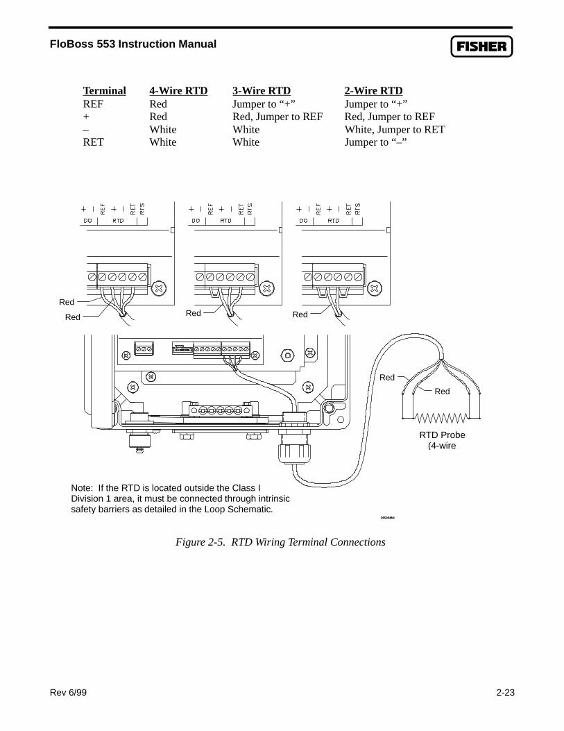
FloBoss 553 Instruction Manual
Rev 6/99
Terminal 4-Wire RTD 3-Wire RTD 2-Wire RTD REF Red Jumper to “+” Jumper to “+”+ Red Red, Jumper to REF Red, Jumper to REF– White White White, Jumper to RETRET White White Jumper to “–”
Figure 2-5. RTD Wiring Terminal Connections
Red
Red Red Red
Red
Red
RTD Probe(4-wire
Note: If the RTD is located outside the Class IDivision 1 area, it must be connected through intrinsicsafety barriers as detailed in the Loop Schematic.
2-23

FloBoss 553 Instruction Manual
2-24 Rev 6/99
2.5.5 Discrete Output Wiring
WARNING
To ensure safe operation, installation and wiring connections must be made asshown in the Loop Schematic of Appendix A. Only the options listed there maybe used.
A Discrete Output is provided on the FloBoss Main Electronics Board, as shown in Figure 2-6. Thetypical application for this output is a sampler or odorizer control, although it may be used for otherpurposes. The Discrete Output is associated with Discrete Output Point A4.
The DO uses a P-channel MOSFET to switch current-limited power to the positive terminal. Thenegative terminal is internally connected to battery negative. A voltage-limiting diode and a back-EMFdiode are included to help protect the FloBoss electronics.
Because the output is not isolated, care must be used to ensure that the operation of the load does notaffect the operation of the FloBoss. The load should be connected as follows:
♦ DO + Positive load♦ DO - Negative load

FloBoss 553 Instruction Manual
Rev 6/99
2.5.6 Con
The FloBossCommunicaWiring connspecial 3-pinWiring connecard.
Note: Refer to Loop Schematic for deviceparameters, as well as to connect DO to a devicelocated outside the Class I Division 1 area.
Figure 2-6. Discrete Output Terminal Wiring
necting Communications Wiring
has the flexibility to communicate to external devices usingtions take place either through the operator interface port (Lections for the LOI port are made using screw terminals on connector on the bottom of the case is intended for use onctions for the host port are made using screw terminals on
DiscreteDevice
2-25
different protocols.OI) or the host port (COM1).the electronics board (thely in non-hazardous areas). the optional communications

FloBoss 553 Instruction Manual
2-26 Rev 6/99
2.5.6.1 Operator Interface Port Wiring
Figure 2-7 displays the operator interface (LOI) port. The LOI port provides connections for a built-inEIA-232 communications interface to a configuration and monitoring device. The configuration andmonitoring device typically is an IBM-compatible personal computer.
The LOI port is intended primarily for use with the ROCLINK Configuration Software. The LOI portis compatible with RS232-type signals. The signals originate on the Main Electronics Boardterminations and are factory-wired to the three-terminal, cannon-style connector located on the bottomof the enclosure. A prefabricated operator interface cable is available as an accessory from Fisher.
WARNING
Do not use the LOI port on the bottom of the FloBoss enclosure in a hazardouslocation (Class I, Division 1 or 2). Instead, use the Laptop Computer connectorsthat are wired through an intrinsic safety barrier as shown in the Loop Schematic(Appendix A).
An RTS terminal for the LOI port is provided on the Main Electronics Board; however, it is notintended for use in Class I Division 1 areas. The following table shows the signal routing of the MainElectronics Board terminations and the cannon-style connector:
Main Board Cannon Connector Signal BLK 1 CommonWHT 2 RXDRED 3 TXD
If a 9-pin connector is used to connect to the communications ports on the PC, then pin 2 shouldconnect to RXD, pin 3 to TXD, and pin 5 to common.

FloBoss 553 Instruction Manual
Rev 6/99
2.5.6.2 Host
The host port (Ccommunication553 and how to
2.5.7 Dual-V
For information
TXD
RXDCOM
Note: Refer to Loop Schematic to connect LOI signalsto a device located outside the Class I Division 1 area.
2-27
Figure 2-7. Operator Interface Wiring
Port Wiring
OM1) provides communications access to the FloBoss through an optionals card. Section 4 describes the types of communications cards available for the FloBoss make wiring connections to them.
ariable Sensor Wiring
on DVS wiring, refer to Section 3.

FloBoss 553 Instruction Manual
2-28 Rev 6/99
2.6 CALIBRATION
The calibration routines support 5-point calibration, with the three mid-points calibrated in any order.The low-end or zero (Set Zero) reading is calibrated first, followed by the high-end or full-scale (SetSpan) reading. The three mid-points can be calibrated next if desired. The diagnostic Analog Inputs —input voltage and board temperature — are not designed to be calibrated.
The inputs that are supported with the 5-point calibration are:
♦ Differential pressure located at Analog Input Point A1.♦ Static (line) pressure located at Analog Input Point A2.
♦ Temperature (RTD) located at Analog Input Point A3.
The calibration procedure for these inputs is described in Section 3.
FloBoss 553 Instruction Manual
Rev 1/00 2-29
2.7 TROUBLESHOOTING AND REPAIR
This troubleshooting and repair information is designed to help you identify problems and take initialmeasures to correct them. Return faulty FloBoss units to your Fisher Representative for repair orreplacement. To troubleshoot communications cards, refer to Section 4.
NOTE
If the FloBoss 553 is entering the Sleep Mode for no apparent reason, ensurethat the activation values have been set as instructed in Section 1.8.2.
The following tools are typically required for troubleshooting:♦ IBM-compatible personal computer.♦ ROCLINK Configuration Software (runs on the personal computer).♦ Digital multi-meter, Fluke 8060A or equivalent.
The ROCLINK Configuration Software is required for most of the troubleshooting. Refer to theROCLINK Configuration Software User Manual for additional information.
2.7.1 Backup Procedure Before Removing Power
Use the following backup procedure when removing or adding FloBoss components. This procedurepreserves the current FloBoss configuration and data held in RAM.
Before removing power to the FloBoss for repairs, troubleshooting, or enhancements, perform thisbackup procedure. The procedure assumes you are using Revision 2.0 or later of the standardROCLINK Configuration Software.
WARNING
When working on units in a hazardous area, make sure components selectedare listed for use in such areas. Installation and maintenance must beperformed only when the area is known to be non-hazardous.
CAUTION
To avoid circuit damage when working with the unit, use appropriateelectrostatic discharge precautions, such as wearing a grounded wrist strap.
CAUTION
There is a possibility of losing the configuration and historical data whileperforming the following procedure. As a precaution, save the currentconfiguration and historical data to permanent memory as follows.

FloBoss 553 Instruction Manual
2-30 Rev 6/99
1. Launch the ROCLINK Configuration Software.
2. Connect to ROCLINK.
3. Select Collect ROC Data from the File menu.
4. Select All in the Collect ROC Data dialog box.
5. Enter a File Name and click OK .
2.7.2 Resetting the FloBoss
If you are experiencing problems with the FloBoss that appear to be software related, try resetting theFloBoss. As described in the following paragraphs, there are three ways to reset the FloBoss:
♦ Warm Start.♦ Cold Start.♦ Jumper Reset.
For example, if security was enabled on both communication ports of the FloBoss, the settings weresaved to permanent memory, and then the ID and/or Passwords were lost, communications with theFloBoss will be locked out on both ports until a Jumper Reset is performed; then the host port could beused, since its security is disabled by default.
If none of these reset methods seem to help, the FloBoss may need to be returned to the factory forrepair.
2.7.2.1 Warm Start
This re-initialization is performed by setting a parameter in the System Flags. The re-initializationincludes the Tasks, Database, Communication Ports, DVS, and I/O. It does not change the currentconfiguration of any parameters. Refer to Figure 2-8.
1. Launch the ROCLINK Configuration Software.
2. Perform the Backup Procedure in Section 2.7.1, on page 2-29.
3. Select Flags from the System menu option.
4. Set the Warm Start flag to Yes.
5. Press (F8)Save.

FloBoss 553 Instruction Manual
Rev 6/99 2-31
Figure 2-8. ROC System Flags Alternately, you can perform a warm start by removing power from the FloBoss and then restoring it.Make sure that jumper P1 on the Main Electronics Board is in the NORM position for a warm start totake place.
2.7.2.2 Cold Start
This reinitialization is performed by setting a parameter in the System Flags, called Cold Start Options.The reinitialization includes the Tasks, Database, Communication Ports, DVS, I/O, and restoring thesaved configuration if there is one. A Cold Start also includes the following based upon the valueentered in Figure 2-9.
Figure 2-9. Cold Start Options

FloBoss 553 Instruction Manual
2-32 Rev 6/99
1. Launch the ROCLINK Configuration Software. 2. Perform the Backup Procedure in Section 2.7.1, on page 2-29. 3. Select Flags from the System menu option. 4. Click the Cold Start flag Options. Refer to Figure 2-8. 5. Select the type of Cold Start you desire. Select “Restore config and clear all of above” to reset
all options. 6. Click OK . 7. Press (F8)Save.
2.7.2.3 Jumper Reset The FloBoss Main Electronics Board has a jumper located at P1 in the upper right-hand corner of theboard that can be used to perform a special type of cold start. Refer to Figure 2-10. This jumperpermits a power-up reset to re-establish a known operating point. The reset includes reinitializing theTasks, Database, Communication Ports, DVS, and I/O and restoring the factory default configuration.This cold start does not include any of the clearing options available in a Cold Start performed by usingROCLINK (see Section 2.7.2.2).
NORMRST
P1
DOC0277U
Figure 2-10. Reset Jumper Shown in Normal Position
WARNING
Power should be removed from outside a hazardous area before working in it. Ifthis is not possible, ensure that steps have been taken (such as ventilation) to makethe area non-hazardous before applying or removing power in the classified area.

FloBoss 553 Instruction Manual
Rev 6/99 2-33
CAUTION
This type of reset restores the factory configuration defaults. Any user-enteredconfiguration data will be lost; therefore, try to back up any required data beforeperforming this reset.
To reset the FloBoss and load the factory default values into all configurable parameters:
1. Perform the Backup Procedure in Section 2.7.1, on page 2-29.
2. Disconnect the INPUT POWER terminal block to remove power.
3. Remove the four phillips-head screws securing the cover over the electronics board. Lift offthe cover and move the P1 jumper to the reset (RST) position.
To enact a reset, power up the unit with the jumper installed.
4. Apply power by plugging in the INPUT POWER terminal block.
5. Remove the P1 jumper on the Main Electronics Board and install it in the normal (NORM )position. Replace the cover and secure it with the four screws.
6. Refer to Section 2.7.3 and perform the After Installing Components.
2.7.3 After Installing Components
After removing power to the FloBoss and installing components as needed, perform the following stepsto start your FloBoss and reconfigure your data. The procedure assumes you are using Version 2.0 orlater of the standard ROCLINK Configuration Software.
WARNING
When working on units in a hazardous area, make sure components selectedare listed for use in such areas. Installation and maintenance must beperformed only when the area is known to be non-hazardous.
CAUTION
Ensure all input devices, output devices, and processes remain in a safe stateupon restoring power.

FloBoss 553 Instruction Manual
2-34 Rev 6/99
CAUTION
To avoid circuit damage when working with the unit, use appropriateelectrostatic discharge precautions, such as wearing a grounded wrist strap.
1. Reconnect power to the FloBoss by inserting the INPUT POWER terminal block back into
its socket. 2. Launch the ROCLINK Configuration Software, log in, and connect to the FloBoss.
3. Verify that the configuration is correct. If it is not, continue by configuring the neededitems. If major portions or the entire configuration needs to be reloaded, perform theremaining steps.
4. Select Download from the File menu, and in the resultant sub-menu. 5. Select Disk Config. to ROC. 6. In the dialog box that appears (see Figure 2-11), select the File Name you entered in step 4
of Section 2.7.1, Backup Procedure Before Removing Power, on page 2-29 and click OK .
7. Select the portions (see Figure 2-12) of the configuration you want to load or restore.
8. Press (F8)Download to restore the FloBoss configuration.
Figure 2-11. Open Configuration File

FloBoss 553 Instruction Manual
Rev 6/99 2-35
Figure 2-12. Download Configuration
2.8 SPECIFICATIONS
Refer to the following pages for specifications of the main electronics board.

FloBoss 553 Instruction Manual
2-36 Rev 6/99
Main Specifications
PROCESSOR MEMORY
Motorola 32 bit, running at 14.7 MHz.
Program: 512 Kbyte flash ROM (electricallyprogrammable) for firmware and configuration.
Data: 512 Kbyte SRAM, super capacitor-backed forup to 4 weeks.
Memory Reset: A reset jumper enables a cold startinitialization when used during power-up.
TIME FUNCTIONS
Clock Type: 32 kHz crystal oscillator with regulatedsupply, super capacitor-backed. Year/Month/Dayand Hour/Minute/Second, with Daylight SavingsTime control.
Clock Accuracy: 0.01%.
Watchdog Timer: Hardware monitor expires after1 second and resets the processor.
DIAGNOSTICS
These conditions are monitored and alarmed:SRAM validity/operation, DVS and RTD point fail,input voltages, and enclosure internal temperature.
COMMUNICATIONS PORTS
Local Operator Interface: EIA-232 (RS-232D)format. Software configured; 1200 to 19.2K baudselectable. Screw-cap protected connector.
Host Interface: Depends on the optionalcommunications card installed (see Spec. Sheet3:COM).
USER INTERFACE
2 line by 16 character LCD. Continually updatesapproximately every 3 seconds. See Environmentalspecification for operating temperature.
POWER
6.2 to 16 Vdc at 0.2 amp maximum.
DVS (BUILT-IN)
Interface: High-speed digital interface with power forDVS.
Inputs and Physical Ch aracteristics: See DVSSpecifications table.
WEIGHT
18.0 lb. (8.2 kg) nominal, including DVS andcoupler.
RTD INPUT (BUILT-IN)
Quantity/Type: Single input for a 2, 3, or 4-wireRTD element.
Terminals: “Ref” current source, “+” positive signalinput, “-” negative signal input, and “Ret” return.
Sensing Range: -50 to 100 °C (-58 to 212 °F).
Accuracy (includes linearity, hysteresis,repeatability): ±0.56 C° (1.0 F°) over sensingrange.
Ambient Temperature Effects per 28 C° (50 F°):±0.50 C° (0.90 F°) for process temperatures from-40 to 100 °C (-40 to 212 °F).
Filter: Band-pass hardware filter.
Resolution: 16 bits.
Conversion Time: 100 µsec.
Sample Period: 1 sec minimum.
DISCRETE OUTPUT (BUILT-IN)
Quantity/Type: 1 sourced, high-side switchedoutput.
Terminals: “+” positive output, “-” negative(common).
Voltage: Nominal 5 volts.
Frequency: 1.5 Hz maximum.
Sample Period: 200 ms minimum.
Typical Source Current: 25 mA, with auto reset.
ENVIRONMENTAL
Operating Temperature: -40 to 75 °C (-40 to 167°F), excluding LCD display, which is -25 to 70 °C(-13 to 158 °F).
Storage Temperature: -50 to 85 °C (-58 to 185 °F).
Operating Humidity: 5 to 95%, non-condensing.
Vibration: Meets SAMA PMC 31.1, Section 5.3,Condition 3.
ESD Immunity: Meets IEC 801-2 and EN 50082-2.
RFI Immunity: Meets IEC 801-3 and EN 50082-2.
EFT Immunity: Designed to meet IEC 801-4 andEN 50082-2.
Voltage Surge Immunity: Designed to meet IEC801-5 and EN 61000-4-5.

FloBoss 553 Instruction Manual
Rev 6/99 2-37
Main Specifications
DIMENSIONS
Overall: 16.75 in. H by 10.38 in. W by 6.69 in. D(425 mm by 264 mm by 170 mm). Height includestop mounting flange and DVS.
Wall Mounting: 2.81 in. W by 12.50 in. H (71 mmby 318 mm) between mounting hole (0.38 in.diameter) centers.
Pipestand Mounting: Mounts on 2-inch pipe withU-bolt mounting kit (supplied).
Process Connections: See DVS Specifications.
CLASSIFICATION
FCC Class A and CISPR 22 computing device.
ENCLOSURE
Construction: Fiberglass-reinforced plastic withlockable hasp and gasketed door. Internal structuralmetal is low-copper aluminum alloy. All exposedmetal is stainless steel. Meets CSA Type 4X rating(NEMA 4X equivalent).
Wiring access: Three 0.88 in. pre-punched holes:one in right side, two in bottom.
APPROVALS
Approved as Model W40076 by CSA for hazardouslocations Class I, Division 1, Groups C and D,intrinsically safe.

FloBoss 553 Instruction Manual
2-38 Rev 6/99
[This page is intentionally left blank.]

FloBoss 553 Instruction Manual
Rev 6/99 3-1
SECTION 3 — DUAL-VARIABLE SENSOR
3.1 SCOPE
This section describes the Dual-Variable Sensor (DVS), which provides differential pressure and staticpressure inputs to the FloBoss 553 Flow Manager for orifice flow calculation. Note the DVS is quitesimilar to the Multi-Variable Sensor (MVS) used with the FloBoss 407; however, the MVS can providea temperature input to the FloBoss, while a DVS does not.
3.2 SECTION CONTENTS
This section contains the following information:
Information Section Page NumberScope 3.1 3-1Section Contents 3.2 3-1Description 3.3 3-1Process Connections 3.4 3-2DVS Wiring 3.5 3-2Configuration 3.6 3-3Calibration 3.7 3-5
Verifying Calibration 3.7.1 3-5Calibrating the FloBoss 3.7.2 3-6Zero Shift 3.7.3 3-12
Specifications 3.8 3-13
3.3 DESCRIPTION
The DVS, which uses Rosemount sensor technology, measures differential pressure and absolute orgauge (static) pressure by converting the applied pressure to electrical signals and making the readingsavailable to the Main Electronics Board. The sensor housing screws into an adapter, which in turnmounts with four bolts to the bottom of the FloBoss enclosure. The DVS cable plugs directly into theMain Electronics Board at the P/DP connector.
The readings from the Dual-Variable Sensor are stored in analog inputs on the FloBoss 553. Thedifferential pressure value uses the Analog Input (AI) Point A1 and the static (line) pressure value usesthe AI Point A2. If the alarm for either point is Enabled and the sensor fails to communicate, eitherduring initialization or operation, an alarm is entered in the Alarm Log.

FloBoss 553 Instruction Manual
3-2 Rev 6/99
The DVS uses an interrupt to inform the Main Electronics Board that it is ready for an update. Thismust occur at least once per second. The FloBoss 553 then converts this value and stores it in theproper analog input for access by other functions within the unit. If an update does not occur in the onesecond interval, the sensor is re-initialized. A point fail alarm is set if the sensor does not respond tothe initialization.
3.4 PROCESS CONNECTIONS
Piping from the meter run must be connected to the Dual-Variable Sensor (DVS) of the FloBoss 553.Both the static and differential pressures are piped to female ¼-18 NPT connections on the bottom ofthe DVS. The FloBoss 553 is an upstream device, meaning that the static pressure line normally mustbe connected to the high-pressure side (labeled “H” on the sensor body).
If you need to use the FloBoss 553 as a downstream device:
1. Connect the “H” side of the sensor to downstream pressure, so that flow in relation to the sensoris reversed from its normal direction.
2. Use ROCLINK to configure the meter run for Downstream operation (this automatically adjuststhe static pressure by adding in the differential pressure).
3. Calibrate the differential pressure as described in Section 3.6.
3.5 DVS WIRING
The FloBoss 553 and the Dual-Variable Sensor are shipped from the factory with the wiring connectedas shown in Figure 3-1. The DVS cable connection is made at the P/DP (pressure/differential pressure)terminal connector and plugs directly into the Main Electronics Board at P11.
WARNING
Power should be removed from outside a hazardous area before working in it. Ifthis is not possible, ensure that steps have been taken (such as ventilation) to makethe area non-hazardous before applying or removing power in the classified area.
CAUTION
Always turn power off to the FloBoss 553 before you connect or disconnect signalwiring.

FloBoss 553 Instruction Manual
Rev 6/99 3-3
Figure 3-1. DVS Wiring
The top part of Figure 3-1 displays the FloBoss 553 wiring terminals. The rest of the figure showns howthe DVS ribbon cable connects from the P/PD connector to the DVS unit. The ribbon cable is keyed to fitinto the P/PD connector in only one direction. The DVS comes installed by the factory.
3.6 CONFIGURATION
Use the ROCLINK Configuration Software, Version 2.1 or later, to configure the DVS for a FloBoss553 with Version 2.0 or later firmware. Refer to Section 2.3.2 concerning History Points.
♦ The differential pressure is configured at Analog Input Point Number A1.♦ The static pressure (gauge or absolute) is configured at Analog Input Point Number A2.♦ The Resistance Temperature Detector (RTD) is configured at Analog Input Point Number A3.
The initial pressures are read from the defaults contained within the DVS. The initial range of thedifferential pressure is 0 to 250 inches of water and the static pressure is either 0 to 800 psi (55.15 bar)or 0 to 3600 psi (250 bar) depending upon the sensor installed. The ranges can be changed through thecalibration routines. It is recommended that the turndown on the ranges not be greater than five.
DVS RibbonCable
P/DPConnector

FloBoss 553 Instruction Manual
3-4 Rev 6/99
The Dual-Variable Sensor also supports the conversion of values to Metric units. In Metric mode, boththe differential pressure and the static pressure are in kPa. To enter the Metric mode, using ROCLINKConfiguration Software:
1. Select the System menu.
2. From the pull-down menu, select Information .
3. On the system information display (see Figure 3-2) under Units, enable the Metric field.
4. Press (F8)Save.
Figure 3-2. System Information
The FloBoss automatically adjusts the units, ranges, alarm limits, and calibration factors of thedifferential pressure, static pressure, RTD, and enclosure/battery temperature, to the Metric mode. Toreturn to US units, enable the US field and save this change to the FloBoss. The FloBoss adjusts thevalues to US units for the entire meter run.

FloBoss 553 Instruction Manual
Rev 6/99 3-5
3.7 CALIBRATION
Calibration is performed using the ROCLINK Configuration Software. The procedure allows you toperform a 5-point (minimum, maximum, and up to three intermediate points) calibration of the DVS.
3.7.1 Verifying Calibration
The ROCLINK Configuration Software can be used to verify the calibration. This is normally done asa check to see if a re-calibration is needed. To verify, perform the following steps:
CAUTION
To protect the differential cell of the Dual-Variable Sensor, open the by-pass valveon the valve manifold prior to isolating the sensor from the process. This will keepone side of the differential sensor from being subjected to high pressure while theother side has no pressure applied. This should be done whether you are calibra-ting differential or static pr essure. Refer to Figure 3-7 on page 3-8 for therecommended sequence.
1. Launch the ROCLINK Configuration Software and logon to the FloBoss 553.
2. Select the Calibration pushbutton either from the Quick Setup menu or from the Meter menu.
3. Press the Freeze pushbutton. This displays the Meter Calibration window. Refer to Figure 3-3.The current reading is shown under each meter input as the Freeze Value. These values will beused in the flow calculations while the points are being verified.
Figure 3-3. Meter Calibration Window

FloBoss 553 Instruction Manual
3-6 Rev 6/99
4. Select the Verify function that is listed under the input to calibrate. This displays the VerifyCalibration window as in Figure 3-4.
Figure 3-4. Verify Calibration
5. Apply the desired pressure value to the input.
6. If the Tester Value and the Live Reading are to be logged to the Event log as a record of theverification, select the Log Verify pushbutton.
7. Continue this for all pressures/values that need to be verified.
8. When complete, select the Cancel pushbutton to return to the Meter Calibration window.
9. When the verification for a selected point is complete, you have the choice to verify or calibrateanother input or to complete the verification or calibration. When complete, connect the Dual-Variable Sensor back to the process.
CAUTION
To protect the differential cell of the Dual-Variable Sensor, do not close the by-passvalve on the valve manifold until after process pressure has been reapplied. Thiswill keep one side of the differential sensor from being subjected to high pressurewhile the other side has no pressure applied. Refer to Figure 3-12 on page 3-11.
10. Select the Done pushbutton to close the calibration window, to cancel the freeze values, and tobegin using live readings for the flow calculations.
3.7.2 Calibrating the FloBoss
The ROCLINK Configuration Software is used to perform initial calibration or re-calibration, such asafter an orifice plate is changed in the meter run handled by the FloBoss.
Perform the following steps:
1. Launch the ROCLINK Configuration Software and logon to the FloBoss 553.

FloBoss 553 Instruction Manual
Rev 6/99 3-7
2. Select the Calibration function from either the Quick Setup menu or the Meter menu.
3. Press the Freeze pushbutton. This displays the Meter Calibration window as in Figure 3-5.The current reading is shown under each meter input as the Freeze Value. These values will beused in the flow calculations while the points are being calibrated.
Figure 3-5. Meter Calibration
4. Select the Calibrate pushbutton under the desired input to calibrate Diff Press, Stat Press, orTemperature. This displays the Set Zero calibration window as in Figure 3-6.
Figure 3-6. Set Zero Calibration for Differential Pressure
5. If you are calibrating a pressure input, read the following Caution, and then isolate theDual-Variable Sensor from the process. If you are calibrating a temperature input, proceed toStep 7.
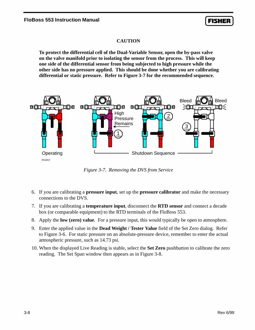
FloBoss 553 Instruction Manual
3-8 Rev 6/99
CAUTION
To protect the differential cell of the Dual-Variable Sensor, open the by-pass valveon the valve manifold prior to isolating the sensor from the process. This will keepone side of the differential sensor from being subjected to high pressure while theother side has no pressure applied. This should be done whether you are calibratingdifferential or static pressure. Refer to Figure 3-7 for the recommended sequence.
1Close
Shutdn2
L H
2Open
L H
3Close
L H
HighPressureRemains
Bleed BleedL H
Operating Shutdown Sequence
Figure 3-7. Removing the DVS from Service
6. If you are calibrating a pressure input, set up the pressure calibrator and make the necessaryconnections to the DVS.
7. If you are calibrating a temperature input, disconnect the RTD sensor and connect a decadebox (or comparable equipment) to the RTD terminals of the FloBoss 553.
8. Apply the low (zero) value. For a pressure input, this would typically be open to atmosphere.
9. Enter the applied value in the Dead Weight / Tester Value field of the Set Zero dialog. Referto Figure 3-6. For static pressure on an absolute-pressure device, remember to enter the actualatmospheric pressure, such as 14.73 psi.
10. When the displayed Live Reading is stable, select the Set Zero pushbutton to calibrate the zeroreading. The Set Span window then appears as in Figure 3-8.

FloBoss 553 Instruction Manual
Rev 6/99 3-9
Figure 3-8. Set Span
11. Apply the desired high value to the input (the top end of the expected operating range). If youare calibrating the Diff Press input, and the DVS is configured for Downstream operation, besure to apply the calibrator pressure to the low (labeled “L”) side of the sensor; the LiveReading will appear as a negative value. Static pressure for Downstream is calibrated the sameas for Upstream.
12. Enter the applied value in the Dead Weight / Tester Value field of the Set Span dialog. Forstatic pressure on an absolute-pressure device, remember to add in the actual atmosphericpressure, such as 300 + 14.73. If you are calibrating the Diff Press input, and the DVS isconfigured for Downstream operation, enter the value as positive, even though the LiveReading is a negative value. The software will automatically compensate.
13. When the Live Reading is stable, select the Set Span pushbutton to calibrate the high reading.The window advances to the Set Midpoint 1 window as in Figure 3-9.
Figure 3-9. Set Midpoint 1
14. If a two-point calibration is to be performed, refer to step 23. 15. If midpoints are to be calibrated, apply the desired pressure or temperature and enter the
applied value in the Dead Weight / Tester Value field. Note that the midpoints can becalibrated in any order.

FloBoss 553 Instruction Manual
3-10 Rev 6/99
16. When the Live Reading is stable, select the Set Mid 1 pushbutton to calibrate this reading. Thedisplay advances to the Set Midpoint 2 window as in Figure 3-10.
Figure 3-10. Set Midpoint 2
17. If a three-point calibration is being performed, refer to step 23.
18. If additional midpoints are to be calibrated, apply the desired pressure or temperature and enterthe applied value in the Dead Weight / Tester Value field.
19. When the Live Reading is stable, select the Set Mid 2 pushbutton to calibrate this reading. The
display advances to the Set Midpoint 3 window as in Figure 3-11.
Figure 3-11. Set Midpoint 3
20. If a four-point calibration is being performed, refer to step 23.
21. If a third midpoint is to be calibrated, apply the desired pressure or temperature and enterthe applied value in the Dead Weight / Tester Value field.
22. When the Live Reading is stable, select the Set Mid 3 pushbutton to calibrate this reading.The display returns to the Meter Calibration window.

FloBoss 553 Instruction Manual
Rev 6/99 3-11
23. When the calibration for a selected point is complete, you have the choice to calibrateanother input or to complete the calibration. If calibration is complete, and you calibratedpressure inputs, read the following Caution and then return the Dual-Variable Sensor toservice.
CAUTION
To protect the differential cell of the Dual-Variable Sensor, do not close the by-passvalve on the valve manifold until after process pressure has been reapplied. Thiswill keep one side of the differential sensor from being subjected to high pressurewhile the other side has no pressure applied. Refer to Figure 3-12.
1aClose
L H
3Open
L H
4Close
L H
start2
L H
Pre-Startup
1bClose
2Open
Startup Sequence
Figure 3-12. Returning the DVS to Service
NOTE
If you calibrated the Differential Pressure input, refer to Section 3.7.3, Zero Shift,before completing the last step.
24. Finally, select the Done pushbutton to cause the calibration window to close, freeze values to becanceled (unfrozen), and live readings to resume being used for the flow calculations. Allcalibration settings that were changed are automatically recorded into the Event Log of theFloBoss.

FloBoss 553 Instruction Manual
3-12 Rev 6/99
3.7.3 Zero Shift
If desired, the Zero Shift procedure can be used after calibrating the pressure inputs. The reason forperforming Zero Shift is because the Differential Pressure is calibrated without line pressure beingapplied to the sensor. When the sensor is connected back to the process after calibration, a shift in thedifferential pressure can occur due to the influence of the line pressure. This effect can be canceled outwith a Zero Shift adjustment.
To check or adjust for Zero Shift, leave the sensor by-pass valve open (to simulate a no-flowcondition), with either line pressure or a normal operating static pressure from the calibrator applied tothe sensor. This applies the same pressure to both sides of the differential pressure diaphragm to give azero differential pressure reading.
Perform the following steps:
1. Ensure the ROCLINK Configuration Software is connect to the FloBoss 553 and running thecalibration procedure.
2. If the meter inputs were already released from the freeze condition, use the Freeze pushbutton.This returns the Meter Calibration window as shown in Figure 3-3.
3. Under the Diff Press input, select the Zero Shift pushbutton to open the Set Zero Shift windowshown in Figure 3-13.
Figure 3-13. Set Zero Shift
4. Check the Reading to determine if a Zero Shift correction needs to be performed.
5. If the reading is not zero, use the Set Zero Shift pushbutton to adjust the Zero Shift. Ifadjustment is not required, use the Cancel pushbutton. You are returned to the MeterCalibration window, where you can select Done to close the calibration window, cancel thefreeze values, and cause the FloBoss to begin using live readings for the flow calculations.
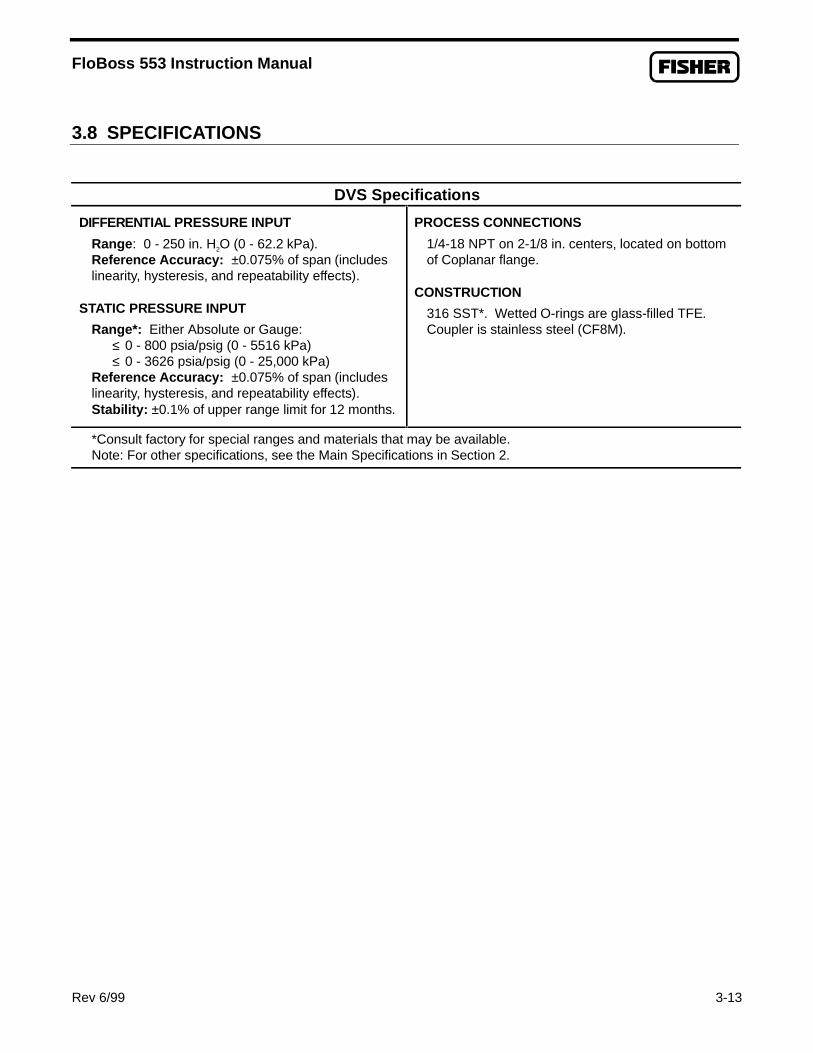
FloBoss 553 Instruction Manual
Rev 6/99 3-13
3.8 SPECIFICATIONS
DVS Specifications
DIFFERENTIAL PRESSURE INPUT
Range : 0 - 250 in. H2O (0 - 62.2 kPa).Reference Accuracy: ±0.075% of span (includeslinearity, hysteresis, and repeatability effects).
STATIC PRESSURE INPUT
Range*: Either Absolute or Gauge: ≤ 0 - 800 psia/psig (0 - 5516 kPa) ≤ 0 - 3626 psia/psig (0 - 25,000 kPa)Reference Accuracy: ±0.075% of span (includeslinearity, hysteresis, and repeatability effects).Stability: ±0.1% of upper range limit for 12 months.
PROCESS CONNECTIONS
1/4-18 NPT on 2-1/8 in. centers, located on bottomof Coplanar flange.
CONSTRUCTION
316 SST*. Wetted O-rings are glass-filled TFE.Coupler is stainless steel (CF8M).
*Consult factory for special ranges and materials that may be available.Note: For other specifications, see the Main Specifications in Section 2.

FloBoss 553 Instruction Manual
3-14 Rev 6/99
[This page intentionally left blank.]

FloBoss 553 Instruction Manual
Rev 6/99 4-1
SECTION 4 — COMMUNICATIONS CARDS
4.1 SCOPE
This section describes the communications cards used with the FloBoss 550-Series Flow Manager.
4.2 SECTION CONTENTS
This section contains the following information:
Information Section Page NumberScope 4.1 4-1Section Contents 4.2 4-1Product Descriptions 4.3 4-1
EIA-232 Serial Communications Card 4.3.1 4-2EIA-485 Serial Communications Card 4.3.2 4-4
Initial Installation and Setup 4.4 4-5Installing Communications Cards 4.4.1 4-5
Connecting Communications Cards to Wiring 4.5 4-7EIA-232 Communications Card Wiring 4.5.1 4-7EIA-485 Communications Card Wiring 4.5.2 4-7
Troubleshooting and Repair 4.6 4-8Replacing a Communications Card 4.6.1 4-8
Communication Cards Specifications 4.7 4-10Serial Card Specifications 4.7.1 4-10
4.3 PRODUCT DESCRIPTIONS
The communications cards provide communications between the FloBoss and a host system or externaldevices. The communications cards install directly onto the Main Electronics Board at P3 and activatethe host port (COM1) when installed. COM1 is configured using ROCLINK. The following cards areavailable:
♦ EIA-232 Serial Communications Card.♦ EIA-485 Serial Communications Card.
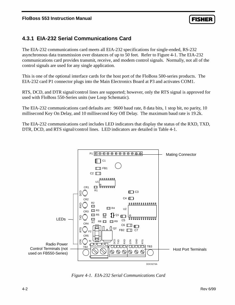
FloBoss 553 Instruction Manual
4-2 Rev 6/99
4.3.1 EIA-232 Serial Communications Card
The EIA-232 communications card meets all EIA-232 specifications for single-ended, RS-232asynchronous data transmission over distances of up to 50 feet. Refer to Figure 4-1. The EIA-232communications card provides transmit, receive, and modem control signals. Normally, not all of thecontrol signals are used for any single application.
This is one of the optional interface cards for the host port of the FloBoss 500-series products. TheEIA-232 card P1 connector plugs into the Main Electronics Board at P3 and activates COM1.
RTS, DCD, and DTR signal/control lines are supported; however, only the RTS signal is approved forused with FloBoss 550-Series units (see Loop Schematic).
The EIA-232 communications card defaults are: 9600 baud rate, 8 data bits, 1 stop bit, no parity, 10millisecond Key On Delay, and 10 millisecond Key Off Delay. The maximum baud rate is 19.2k.
The EIA-232 communications card includes LED indicators that display the status of the RXD, TXD,DTR, DCD, and RTS signal/control lines. LED indicators are detailed in Table 4-1.
P1
DT
RR
TS
TX
DR
XD
DC
D
DC
D
TX
D
RX
D
DT
R
GN
D
RT
SIN
TB3TB2
F2
DOC0274A
CR2
CR1
CR3
CR4
CR5
R2
R3
R5
R7 R8
R6
R1
U1
C2
FB1
C1
C6
C7
C5
C4
C3
FB2
U2
Q2
Q1
R9
R4
Figure 4-1. EIA-232 Serial Communications Card
Radio PowerControl Terminals (not
used on FB550-Series) Host Port Terminals
Mating Connector
LEDs

FloBoss 553 Instruction Manual
Rev 6/99 4-3
Table 4-1. Communications Cards LED Indicators
LEDs STATUS AND ACTIVITY
DCD The DCD data carrier detect LED lights when a valid carrier tone is detected.
DTR The DTR data terminal ready LED lights when a signal from the processorspecifies the modem is ready to answer an incoming call. When the DTR goes off,a connected modem disconnects.
RTS The RTS ready to send LED lights when a signal from the processor specifies themodem is ready to transmit.
RXD The RXD receive data LED blinks when a data signal is being received by thecommunications card. The LED is on for a space and off for a mark.
TXD The TXD transmit data LED blinks when a data signal data is being sent from theprocessor. The LED is on for a space and off for a mark.
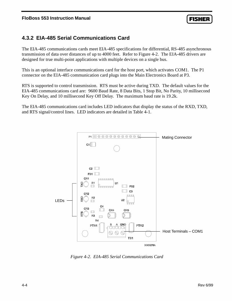
FloBoss 553 Instruction Manual
4-4 Rev 6/99
4.3.2 EIA-485 Serial Communications Card
The EIA-485 communications cards meet EIA-485 specifications for differential, RS-485 asynchronoustransmission of data over distances of up to 4000 feet. Refer to Figure 4-2. The EIA-485 drivers aredesigned for true multi-point applications with multiple devices on a single bus.
This is an optional interface communications card for the host port, which activates COM1. The P1connector on the EIA-485 communication card plugs into the Main Electronics Board at P3.
RTS is supported to control transmission. RTS must be active during TXD. The default values for theEIA-485 communications card are: 9600 Baud Rate, 8 Data Bits, 1 Stop Bit, No Parity, 10 millisecondKey On Delay, and 10 millisecond Key Off Delay. The maximum baud rate is 19.2k.
The EIA-485 communications card includes LED indicators that display the status of the RXD, TXD,and RTS signal/control lines. LED indicators are detailed in Table 4-1.
Figure 4-2. EIA-485 Serial Communications Card
Mating Connector
LEDs
Host Terminals – COM1

FloBoss 553 Instruction Manual
Rev 6/99 4-5
4.4 INITIAL INSTALLATION AND SETUP
Communications card installation is normally performed at the factory when the FloBoss is ordered.However, the modular design of the FloBoss 500-series makes it easy to change hardwareconfigurations in the field. The following procedures assume that this is a first-time installation of acommunications card in a FloBoss and that the unit is currently not in service. For units currentlyin service, refer to the procedures in Section 4.6, “Troubleshooting and Repair.”
CAUTION
When installing units in a hazardous area, ensure that the componentsselected are listed for use in such areas. Work only in an area known to benon-hazardous.
CAUTION
Be sure to use proper electrostatic handling, such as wearing a grounded wriststrap, or components on the circuit cards may be damaged.
4.4.1 Installing Communications Cards
All communications cards install into the FloBoss in the same manner.
1. Ensure power is removed, such as by unplugging the INPUT POWER connector from itssocket. For a FloBoss 550-Series unit, remove the cover from over the Main ElectronicsBoard by removing the four Phillips-head screws securing it.
2. Plug the communications card connector into connector P3 on the Main Electronics Board.
Figure 4-3 shows the card location. Gently press the connectors together until the cardcontacts a stand-off.
3. Ensuring that the three stand-off holes in the communications card line up with the
compression stand-offs on the Main Electronics Board, firmly press the communicationscard onto the stand-offs.
4. Connect the wiring to the communications card (see Section 4.5). For a FloBoss 550-Seriesunit, route this wiring through the slot on the left-hand side of the cover, reattaching thecover with the four screws.
5. Using the ROCLINK Configuration Software, configure communication parameters as
needed by the application. Be sure to save the configuration to permanent memory.

FloBoss 553 Instruction Manual
4-6 Rev 6/99
Figure 4-3. Communications Card Location
CommunicationsCard
MatingConnector
Stand-off HoleStand-off Hole
Stand-off Hole

FloBoss 553 Instruction Manual
Rev 6/99 4-7
4.5 CONNECTING COMMUNICATIONS CARDS TO WIRING
Signal wiring connections to the communications cards are made using the terminal block located onthe serial communications cards.
4.5.1 EIA-232 Communications Card Wiring
The EIA-232 communications card provides for RS232 signals on the host port. This communicationscard also provides a means to switch power to external devices (In and Out terminals); however, thisfeature should not be used on the FloBoss 550-Series due to the energy restrictions of Intrinsic Safetyrequirements. LEDs are provided for diagnostic functions. The screw terminals and their functions areas follows:
Terminal FunctionRXD Receive dataTXD Transmit dataDTR* Data Terminal ReadyRTS Ready to SendDCD* Data Carrier DetectGND GroundIN* Power inputOut* Switched power output
*Do not use for FloBoss 550-Series, due to requirements of Loop Schematic.
For the FloBoss 550-Series, refer to the Loop Schematic in Appendix A for details of using IS barrierswith the approved signal lines.
4.5.2 EIA-485 Communications Card Wiring
The EIA-485 communications card provides for RS-485 signals on the host port located at COM1.Wiring should be twisted-pair cable. This card also provides additional protection for the externalwiring and the board circuitry. LEDs are provided for diagnostic functions. The terminals and theirfunctions are as follows:
Terminal FunctionA RS485 positiveB RS485 negativeGND Ground
For the FloBoss 550-Series unit, refer to the Loop Schematic in Appendix A for details of using ISbarriers with these signal lines.

FloBoss 553 Instruction Manual
4-8 Rev 6/99
4.6 TROUBLESHOOTING AND REPAIR
There are no user serviceable parts on the communications cards. If a card appears to be operatingimproperly, verify that the card is set up according to the information contained in Section 4.4, “InitialInstallation and Setup.” If it still fails to operate properly, the recommended repair procedure is toremove and replace the card. The faulty card should be returned to your Fisher Representative forrepair or replacement.
Follow the procedures below to help ensure data is not lost and equipment is not damaged duringreplacement of a communications card.
4.6.1 Replacing a Communications Card
If you are installing a communications card for the first time, refer to Section 4.4. To remove andreplace a communications card on an in-service FloBoss, perform the following procedure. Be sure toobserve the cautions to avoid losing data and damaging equipment.
WARNING
Before working in a hazardous area, ensure that appropriate precautions have beentaken, such as ventilating the area to make it non-hazardous.
CAUTION
When repairing units in a hazardous area, ensure that the components selected arelisted for use in such areas. Change components only in an area known to be non-hazardous.
CAUTION
There is a possibility of losing the FloBoss 500-series configuration and historicaldata while performing the following procedure. As a precaution, save the currentconfiguration and historical data to permanent memory as instructed in Section2.7.1, Backup Procedure.
CAUTION
Be sure to use proper electrostatic handling, such as wearing a grounded wriststrap, or components on the circuit cards may be damaged.

FloBoss 553 Instruction Manual
Rev 6/99 4-9
CAUTION
During this procedure, all power will be removed from the FloBoss and devicespowered by the FloBoss. Ensure that all connected input devices, output devices,and processes will remain in a safe state when power is removed from the FloBossand also when power is restored to the FloBoss.
1. Refer to Section 2.7.1 and perform the RAM Backup Procedure. 2. Remove the INPUT POWER connector from its socket. For a FloBoss 550-Series unit,
also remove the four Phillips-head screws securing the MCU cover and lift the cover out.
3. Disconnect existing wiring to the communications card, labeling or marking wires asneeded.
4. Using a rocking motion, gently disengage the two stand-off connectors located at the
bottom of the communications card. 5. Using a rocking motion, gently disengage the stand-off connector located at the top, middle
of the communications card. 6. Using a rocking motion, disengage the connectors at P1, pull the card free from the Main
Electronics Board at P3. 7. To reinstall a communications card, orient the card with the P1 connectors on the
communications card mating with the connectors at P3 on the Main Electronics Board.Plug the card into its mating connectors and gently press until the connectors firmly seat.
8. Using a rocking motion, gently engage the three stand-off connectors.
9. Connect the wiring to the communications card (see Section 4.5). For a FloBoss 550-Seriesunit, route the wiring through the slot on the left-hand side of the cover, reattaching thecover with the four screws.
10. Reconnect power by plugging in the INPUT POWER connector. 11. Check the configuration data and FSTs, and load or modify them as required. 12. Verify that the FloBoss 500-series performs as required. 13. Perform the After Installing Components detailed in Section 2.7.3.
If you changed the configuration, save the configuration data to Flash ROM. If you changed theconfiguration, history database, or FSTs, save them to disk. See Section 2.7.1 for more information.

FloBoss 553 Instruction Manual
4-10 Rev 6/99
4.7 COMMUNICATION CARDS SPECIFICATIONS
The following subsection lists the specifications for the serial communications cards.
4.7.1 Serial Card Specifications
EIA-232DCARD
EIA-485CARD
Meets EIA-232 standard for single-ended data transmission overdistances of up to 50 feet (15 m).
Data Rate: Selectable from 1200 to19.2k baud.
Format: Asynchronous, 7 or 8-bit(software selectable) with fullhandshaking.
Parity: None, odd, or even(software selectable).
Meets EIA-485 standard for differ-ential data transmission overdistances of up to 4000 feet (1220meters) for multiple devices.
Data Rate: Selectable from 1200 to19.2k baud.
Format: Asynchronous, 7 or 8-bit(software selectable).
Parity: None, odd, or even(software selectable).
LEDINDICATORS
POWERREQUIRE-MENTS
ENVIRON-MENTAL
WEIGHT
DIMENSIONS
APPROVALS
Individual LEDs for RXD, TXD,and RTS signals. EIA-232D cardalso has LEDs for DTR and DCD.
4.75 to 5.25 Vdc, 0.03 W maxi-mum, supplied by processorboard.
Operating Temperature: -40 to75° C (-40 to 167° F).
Storage Temperature: -50 to85° C (-58 to 185° F).
Operating Humidity: To 95%relative, non-condensing.
0.8 oz. (23 g) nominal.
0.7 in. H by 2.0 in. W by 2.75in. L (18 by 51 by 70 mm).
See Loop Schematic.

FloBoss 553 Instruction Manual
Rev 6/99 A-1
APPENDIX A — LOOP SCHEMATIC
A.1 SCOPE
This appendix provides the Loop Schematic (drawing W20268) for Model W40076, which covers theapproved intrinsic safety installation/wiring for the FloBoss 553 Flow Manager.
Although the Loop Schematic specifies the requirements for safety barriers, the following intrinsicallysafe barriers are specifically recommended:
Input Power Barrier: Stahl 9001/01-158-390-10LOI or RS-232/RS-485 Barrier: Stahl 9002/22-240-160-00Discrete Output: Stahl 9001/01-086-390-10RTD Input: Stahl 9002/22-032-300-11
A.2 LOOP SCHEMATIC DRAWINGS
The Loop Schematic consists of three sheets, as shown on the following pages.

FloBoss 553 Instruction Manual
A-2 Rev 6/99

FloBoss 553 Instruction Manual
Rev 6/99 A-3

FloBoss 553 Instruction Manual
A-4 Rev 6/99

FloBoss 553 Instruction Manual
Rev 6/99 G-1
GLOSSARY OF TERMS
AA/D — Analog to Digital.
AGA — American Gas Association.
AWG — American Wire Gauge.
AI — Analog Input.
AO — Analog Output.
Analog — Analog data is represented by a continuous variable, such as an electrical current signal.
AP — Absolute Pressure.
API — American Petroleum Institute.
Area — A user defined grouping of database entities.
ASCII — American Standard Code for Information Interchange.
Attribute — A parameter that provides information about an aspect of a database point. For example,the alarm attribute is an attribute that uniquely identifies the configured value of an alarm.
BBTU — British Thermal Unit, a measure of heat energy.
Built-in I/O — Input/Output channels that are fabricated into the ROC or FloBoss and do notrequire a separate module. Also called “on-board” I/O.
CC1D1 — Shorthand for Class I, Division 1 hazardous area.
C1D2 — Shorthand for Class I, Division 2 hazardous area.
Coil — Digital output, a bit to be cleared or set.
COM1 — Communications port on the ROC364 that may be used for host communications. Onthe FloBoss 407, this Comm port is built-in for RS-232 serial communications. For the FloBoss500-series, this is the Host port.
COM2 — Communications port on the ROC364 or FloBoss 407 that may be used for hostcommunications.
COMM — Communications port on the ROC306 or ROC312 that may be used for hostcommunications.
Configuration — Refers either to the process of setting up the software for a given system or theresult of performing this process. The configuration activity includes editing the database, buildingschematic displays and reports, and defining user calculations. Typically, the software setup of adevice that can often be defined and changed. Can also mean the hardware assembly scheme.
CPU — Central Processing Unit.
CRC — Cyclical Redundancy Check.

FloBoss 553 Instruction Manual
G-2 Rev 6/99
CSA — Canadian Standards Association.
CTS — Clear to Send modem communications signal.
DD/A — Digital to Analog.
DB — Database.
dB — Decibel. A unit for expressing the ratio of the magnitudes of two electric signals on alogarithmic scale.
DCD — Data Carrier Detect modem communications signal. Also, Discrete Control Device — Adiscrete control device energizes a set of discrete outputs for a given setpoint and matches thedesired result against a set of discrete inputs.
Deadband — A value that is an inactive zone above the low limits and below the high limits. Thepurpose of the deadband is to prevent a value such as an alarm from being set and clearedcontinuously when the input value is oscillating around the specified limit. This also preventsthe logs or data storage location from being over-filled with data.
DI — Discrete Input.
Discrete — Input or output that is non-continuous, typically representing two levels such as on/off.
DO — Discrete Output.
DMM — Digital multimeter.
DP — Differential Pressure.
DSR — Data Set Ready modem communications signal.
DTR — Data Terminal Ready modem communications signal.
Duty Cycle — Proportion of time during a cycle that a device is activated. A short duty cycleconserves power for I/O channels, radios, an such.
DVM — Digital voltmeter.
DVS — Dual-Variable Sensor. Provides static and differential pressure inputs to certain FloBoss500-series Flow Managers.
EEEPROM — Electrically Erasable Programmable Read-Only Memory, a form of permanent
memory.EDS — Electronic Static Discharge.
EFM — Electronic Flow Metering or Measurement.
EIA-232 — Serial Communications Protocol using three or more signal lines, intended for shortdistances.
EIA-422 — Serial Communications Protocol using four signal lines.
EIA-485 — Serial Communications Protocol requiring only two signal lines. Can allow up to 32devices to be connected together in a daisy-chained fashion.
EMF — Electro-motive force.

FloBoss 553 Instruction Manual
Rev 6/99 G-3
EMI — Electro-magnetic interference.
ESD — Electro-static discharge.
EU — Engineering Units. Units of measure, such as MCF/DAY.
FFirmware — Internal software that is factory-loaded into a form of ROM. In the ROC or FloBoss,
the firmware supplies the software used for gathering input data, converting raw input datacalculated values, storing values, and providing control signals.
FlashPAC Module — ROM and RAM module that contains the operating system, applicationsfirmware, and communications protocol in a ROC300-series unit.
Flash ROM — A type of read-only memory that can be electrically re-programmed. It is a form ofpermanent memory (needs no backup power). Also called Flash memory.
FloBoss — A specialized Remote Operations Controller (ROC), Fisher Control’s microprocessor-based unit that provides remote monitoring and control.
Force — Write an ON/OFF, True/False, or 1/0 value to a coil.
FM — Factory Mutual.
FPV — Supercompressibility Factor.
FSK — Frequency Shift Keyed.
FST — Function Sequence Table, a type of program that can be written by the user in a high-levellanguage designed by Fisher Controls.
GGFA — Ground Fault Analysis.
GND — Electrical ground, such as used by the ROC power supply.
GP — Gauge Pressure.
GV101 — Configuration software used to configure ROC units to gather data, as well as most otherfunctions.
GV110 — A host computer system software with one or more DOS-based personal computers that runthe GV110 operations software and are linked to the field with a communications system. The hostcomputer system software runs as a real-time operating system, and can monitor and controloperations in the field as they actually happen.
HHART — Highway Addressable Remote Transducer.
Holding Register — Analog output number value to be read.
hw — Differential pressure.

FloBoss 553 Instruction Manual
G-4 Rev 6/99
I, JID — Identification.
IEC — Industrial Electrical Code.
IEEE — Institute of Electrical and Electronic Engineers. The Open System Interconnection (OSI)reference model and an international standard for the organization of local area networks(LANs) established by the International Standards Organization (ISO) and the IEEE.
IMV — Integral Multiplier Value.
Input — Digital input, a bit to be read.
Input Register — Input numeric value to be read.
I/O — Input/Output.
I/O Module — Module that plugs into an I/O slot on a ROC to provide an I/O channel.
IRQ — Interrupt Request. Hardware address oriented.
IS — Intrinsic Safety or Intrinsically Safe.
IV — Integral Value.
KKbytes — Kilobytes.
kHz — Kilohertz.
LLCD — Liquid Crystal Display. Display-only device used for reading data.
LDP — Local Display Panel. A display-only device that plugs into a ROC300-series unit via aparallel interface cable. The LDP consists of a 4-line by 20-character alphanumeric display andfour pushbuttons used to access information stored by the ROC.
LED — Light-emitting diode.
LOI — Local Operator Interface. Refers to the serial (RS-232) port on the ROC or FloBossthrough which local communications are established, typically for configuration softwarerunning on a PC.
LPM — Lighting Protection Module. Use this module to provide lightning and power surgeprotection for ROCs and FloBoss units.
LRC — Longitudinal Redundancy Checking error checking.
MmA — Milliamps.
MCU — Master Controller Unit.
Modular I/O — I/O channels provided on a ROC using I/O modules. See I/O Module.
MMBTU — Million British Thermal Units.
MPU — Microprocessor Unit.

FloBoss 553 Instruction Manual
Rev 6/99 G-5
MVS — Multi-Variable Sensor. The MVS provides differential pressure, static pressure, andtemperature inputs to the FloBoss 407 for orifice flow calculation.
mV — Millivolts or 0.001 volt.
mW — Milliwatts or 0.001 watt.
NNEC — National Electrical Code.
NEMA — National Electrical Manufacturer’s Association.
OOH — Off-Hook modem communications signal.
Off-line — Accomplished while the target device is not connected (by a communications link). Forexample, off-line configuration is configuring a ROC in a electronic file that is later loaded intothe ROC.
Ohms — Units of electrical resistance.
On-line — Accomplished while connected (by a communications link) to the target device. Forexample, on-line configuration is configuring a ROC while connected to it, so that currentparameter values are viewed and new values can be loaded immediately.
Opcode — Type of message protocol used by the ROC to communicate with the configurationsoftware, as well as host computers with ROC driver software.
P, QParameter — A property of a point that typically can be configured or set. For example, the Point
Tag ID is a parameter of an Analog Input point. Parameters are normally edited by usingconfiguration software running on a PC.
PC — Personal Computer
Pf — Flowing pressure.
P/DP — Pressure/Differential Pressure.
PI — Pulse Input.
PID — Proportional, Integral, and Derivative control feedback action.
PIT — Periodic Timer Interrupt.
Point — Software-oriented term for an I/O channel or some other function, such as a flowcalculation. Points are defined by a collection of parameters.
Point Number — The rack and number of an I/O point as installed in the ROC system.
Point Type — The point type attribute defines the database point to be one of the possible types ofpoints available to the system. The point type determines the basic functions of a point.
Preset — Number value previously determined for an register.
PRI — Primary PID control loop.
PSTN — Public switched telephone network.

FloBoss 553 Instruction Manual
G-6 Rev 6/99
PT — Process Temperature.
PTT — Push-to-talk signal.
Pulse — Transient variation of a signal whose value is normally constant.
PV — Process variable or process value.
RRack — For a ROC, a rack is a row of slots into which I/O modules may be plugged. The rack is
given a letter to physically identify an I/O channel location, such as “A” for the first rack. Built-in I/O channels are assigned a rack identifier of “A,” while diagnostic I/O channels areconsidered to be in rack “E”.
RAM — Random Access Memory. In a ROC or FloBoss, it is used to store history, data, most userprograms, and additional configuration data.
RBX — Report-by-exception. In a ROC or FloBoss, it always refers to spontaneous RBX in whichthe ROC contacts the host to report an alarm condition.
RFI — Radio frequency interference.
RI — Ring Indicator modem communications signal.
ROC — Remote Operations Controller, Fisher Control’s microprocessor-based unit that providesremote monitoring and control.
ROCLINK — Configuration software used to configure ROC or FloBoss units to gather data, aswell as most other functions.
ROCPAC Module — ROM and RAM module that contains the operating system, applicationsfirmware, and communications protocol in a ROC300-series unit.
ROM — Read-only memory. Typically used to store firmware. Flash memory.
RTC — Real-time clock.
RTD — Resistance Temperature Detector.
RTS — Ready-to-Send modem communications signal.
RTU — Remote Terminal Unit.
RTV — Room Temperature Vulcanizing, typically a sealant or caulk like silicone rubber.
RXD — Received data communications signal.
SSAMA — Scientific Apparatus Maker’s Association.
Script — The program instructions (script) embedded within an object.
Soft Points — A type of ROC point with generic parameters that can be configured to hold data asdesired by the user.
SP — Setpoint or Static Pressure.
SPI — Slow Pulse Input.
SPK — Speaker.

FloBoss 553 Instruction Manual
Rev 6/99 G-7
SRAM — Static Random Access Memory. Stores data as long as power is applied; typicallybacked up by a lithium battery or supercapacitor.
SRBX – Spontaneous Report-By-Exception. Refer to RBX.
SVA — Signal Value Analog.
SVD — Signal Value Discrete.
T-ZTDI — Timed Discrete Input or Time Duration Input.
TDO — Timed Discrete Output or Time Duration Output.
Tf — Flowing temperature.
TLP — Type (of point), Logical (or point) number, and Parameter number.
TXD — Transmitted data communications signal.

FloBoss 553 Instruction Manual
G-8 Rev 6/99
[This page intentionally left blank.]

FloBoss 553 Instruction Manual
Rev 6/99 I-1
INDEX
Numerical1985 AGA
Flow Calculations..................................................2-31992 AGA
Flow Calculation...................................................2-432-bit CMOS Microprocessor....................................1-5
AA/D ..........................................................................G-1Accessories................................................................1-7Additional Information...............................................1-2After Installing Components.....................................2-33AGA..................................................................2-3, G-1AI
See Analog Inputs................................................G-1Alarm Log .................................................................2-7Analog......................................................................G-1Analog Inputs ............................................................3-1
RTD....................................................................2-13Antennas....................................................................1-9AO
See Analog Outputs..............................................G-1AP ............................................................................G-1API....................................................................2-3, G-1Approvals................................................................1-10Area.......................................................................... G-1ASCII .......................................................................G-1Attribute.................................................................... G-1Automatic Self Tests................................................2-14AWG........................................................................G-1
BBackup Procedures..................................................2-29
After Installing Components ................................2-33BTU .........................................................................G-1Built-in I/O ...............................................................G-1
CC Prime .....................................................................2-6Calculations
1985 AGA.............................................................2-31992 Flow.............................................................2-4Input and Extension........................................2-4, 2-5Instantaneous Rate..........................................2-4, 2-5
Calibration...............................................................2-28Dual-Variable Sensor............................................3-5I/O Channels .......................................................1-21
Cathodic Protection................................................... 1-12
Class I.....................................................................1-10Clock
Real-Time...........................................................2-13Coil...........................................................................G-1Cold Start................................................................2-31COM1..............................................................2-12, G-1COM2.......................................................................G-1COMM .....................................................................G-1Comm Port
Host....................................................................2-12Operator Interface...............................................2-11
Communication Ports ..............................................2-11Communications
Connectors .........................................................2-12Wiring ................................................................2-25
Communications Cards.............................................. 4-1Descriptions.......................................................... 4-1EIA-232 ............................................................... 4-2EIA-485 ............................................................... 4-4Installation............................................................ 4-5LED Indicators ..................................................... 4-3Location ............................................................... 4-6Replacing ............................................................. 4-8Specifications.....................................................4-10Troubleshooting.................................................... 4-8Wiring .................................................................. 4-7
Configuration............................................................G-1Dual-Variable Sensor............................................ 3-3Verify................................................................... 3-5
Contents............................................................. 3-1, 4-1CPU ..........................................................................G-1CRC..........................................................................G-1CSA..........................................................................G-2CTS ..........................................................................G-2
DD/A...........................................................................G-2Daily Historical Logs................................................ 2-7dB.............................................................................G-2DB ............................................................................G-2DCD .........................................................................G-2Deadband..................................................................G-2DI
See Discrete Inputs...............................................G-2Diagnostic................................................................. 1-5Diagnostic Inputs....................................................2-13Differential Pressure.............2-3, 2-6, 2-28, 3-2, 3-3, G-5Dimensions...................................................... 1-3, 1-14Discrete.....................................................................G-2Discrete Outputs............................................... 1-5, 2-12

FloBoss 553 Instruction Manual
I-2 Rev 6/99
Wiring.................................................................2-24Division 2................................................................1-10DMM .......................................................................G-2DO .......................................................... 1-5, 2-12, 2-18
See Discrete Outputs ............................................G-2Downstream Usage of DVS.......................................3-2DP ............................................................................G-2DSR..........................................................................G-2DTR ..................................................................4-3, G-2Dual-Variable Sensor
Calibration ............................................................3-5Configuration........................................................3-3Description............................................................3-1DVS......................................................................3-1Specifications......................................................3-13Wiring...................................................................3-2
Duty Cycle ...................................................... 1-15, G-2DVM ........................................................................G-2DVS ..................................................................1-5, G-2
Downstream Usage................................................3-2Upstream Usage....................................................3-2
EEDS..........................................................................G-2EEPROM.................................................................G-2EFM ..........................................................................1-3EIA-232....................................................................G-2EIA-232 Communications Cards................................4-2EIA-422....................................................................G-2EIA-485....................................................................G-2EIA-485 Communication Cards.................................4-4Electrical Isolation .................................................... 1-11Electromagnetic Interference....................................1-12Electronics Board.......................................................2-9EMF .........................................................................G-2EMI........................................................ 1-12, 2-18, G-3Enclosure
Dimensions...........................................................1-3Energy Accumulation .........................................2-4, 2-5Energy, Instantaneous................................................2-6Environmental
Requirements ........................................................1-8ESD..........................................................................G-3EU............................................................................G-3Event Log..................................................................2-7Extension Calculation ................................................2-5
FFigure 1-1. FloBoss 553 Flow Manager.....................1-4Figure 1-2. Main Electronics Board...........................1-6Figure 1-3. Outline and Mounting Dimensions........1-14Figure 1-4. Solar Insolation in Hours for the UnitedStates .....................................................................1-18
Figure 2-1. Main Electronics Board ........................2-10Figure 2-2. I/O Terminal.........................................2-18Figure 2-3. Earth Ground Connection .....................2-20Figure 2-4. Location of Input Power Connector.......2-21Figure 2-5. RTD Wiring Terminal Connections .2-23Figure 2-6. Discrete Output Terminal Wiring..........2-25Figure 2-7. Operator Interface Wiring .....................2-27Figure 2-8. ROC System Flags................................2-31Figure 2-9. Cold Start Options ................................2-31Figure 2-10. Reset Jumper Shown in NormalPosition.................................................................2-32
Figure 2-11. Open Configuration File .....................2-34Figure 2-12. Download Configuration.....................2-35Figure 3-1. DVS Wiring........................................... 3-3Figure 3-2. System Information................................ 3-4Figure 3-3. Meter Calibration Window...................... 3-5Figure 3-4. Verify Calibration................................... 3-6Figure 3-5. Meter Calibration.................................... 3-7Figure 3-6. Set Zero Calibration for DifferentialPressure................................................................... 3-7
Figure 3-7. Removing the DVS from Service............ 3-8Figure 3-8. Set Span ................................................. 3-9Figure 3-9. Set Midpoint 1........................................ 3-9Figure 3-10. Set Midpoint 2.................................... 3-10Figure 3-11. Set Midpoint 3.................................... 3-10Figure 3-12. Returning the DVS to Service.............3-11Figure 3-13. Set Zero Shift .....................................3-12Figure 4-1 ................................................................. 4-2Figure 4-1. EIA-232 Serial Communications Card.... 4-2Figure 4-2. EIA-485 Serial Communications Card.... 4-4Figure 4-3. Communications Card Location.............. 4-6Firmware.....................................................1-7, 2-3, G-3Flash Memory........................................................... 2-9Flash ROM.........................................................1-5, G-3FlashPAC..................................................................G-3FloBoss.....................................................................G-3FloBoss Flow Manager.............................................. 1-1Flow and Energy Accumulation.......................... 2-4, 2-5Flow Calculations
1985 AGA............................................................ 2-3Flow Measurement.................................................... 2-3Flow Time.......................................................... 2-4, 2-5Flow, Instantaneous................................................... 2-6Flowing Minutes....................................................... 2-6FM............................................................................G-3Force.........................................................................G-3FPV ..........................................................................G-3FSK ..........................................................................G-3FST....................................................................2-8, G-3Function Sequence Table (FST) User Manual............ 1-2Functions.................................................................. 2-3
GGFA..........................................................................G-3

FloBoss 553 Instruction Manual
Rev 6/99 I-3
GND.........................................................................G-3GP ............................................................................G-3Grid Impedance ........................................................ 1-11Ground Rod.............................................................. 1-11Grounding
Earth Ground....................................................... 1-11Wiring Requirements...........................................1-11
Groups C, and D......................................................1-10GV101......................................................................G-3GV110......................................................................G-3
HHardware Watchdog................................................2-14HART.......................................................................G-3Hazardous Locations................................................1-10History Log...............................................................2-6History Points............................................................2-6Holding Register.......................................................G-3Host Port........................................................2-11, 2-12
Wiring.................................................................2-27Hourly Historical Log................................................2-6hw ............................................................................G-3
II/O............................................................................G-4
Built-in .................................................................1-5I/O Channel
Power Consumed................................................1-15I/O Module...............................................................G-4I/O Power Requirements..........................................1-15I/O Terminals ..........................................................2-18I/O Wiring Requirements .........................................1-12ID.............................................................................G-4IEC...........................................................................G-4IEEE.........................................................................G-4Impedance
Grid ....................................................................1-11IMV..........................................................................G-4Information
Additional .............................................................1-2Input.........................................................................G-4Input and Extension Calculation..........................2-4, 2-5INPUT POWER......................................................2-18Input Register ...........................................................G-4Installation
Communications Cards..........................................4-5Guidelines.............................................................1-8
Instantaneous Rate Calculations..........................2-4, 2-5Integral Multiplier Value............................................2-6
IMV......................................................................2-5Integral Value ............................................................2-6
IV .........................................................................2-5IRQ ..........................................................................G-4ISO...........................................................................G-4
Isolation....................................................................1-11IV .............................................................................G-4
JJumper .................................................................... 2-32
KKbytes.......................................................................G-4kHz...........................................................................G-4
LLAN..........................................................................G-4LCD.................................................................2-11, G-4LDP ..........................................................................G-4LED..........................................................................G-4LEDs
Communications Cards......................................... 4-3Liquid Crystal Display...................................... 1-4, 2-11Local Operator Interface
LOI .......................................................1-5, 1-7, 2-11LOI Wiring.........................................................2-26
LOI ..................................................................2-18, G-4Loop Schematic.........................................................A-1Low Battery ............................................................2-15Low Power Modes..................................................2-14LPM..........................................................................G-4LRC..........................................................................G-4
MmA............................................................................G-4Main Electronics Board .......................1-4, 1-6, 2-9, 2-10
Specifications.....................................................2-35MCU.........................................................................G-4MCU Board.............................................................. 2-9MCU PWR.............................................................2-18Memory .................................................................... 2-9Metric ....................................................................... 3-4Microprocessor................................................... 1-5, 2-9Minute Historical Log ............................................... 2-6Modbus....................................................................2-8Modular I/O ..............................................................G-4MOSFET................................................................2-24Mounting........................................................1-13, 1-14MPU .........................................................................G-4mV............................................................................G-5MVS ..................................................................3-1, G-5mW...........................................................................G-5
NNational Electrical Code
NEC ...................................................................1-10

FloBoss 553 Instruction Manual
I-4 Rev 6/99
NEC .........................................................................G-5NEMA......................................................................G-5NORM.....................................................................2-33
OOff-line.....................................................................G-5OH ...........................................................................G-5Ohms........................................................................G-5On-line .....................................................................G-5Opcode.....................................................................G-5Operation.................................................................1-21Operator Interface Port....................................2-11, 2-26
LOI ................................................................1-5, 1-7Wiring.................................................................2-26
Options......................................................................1-7OSI...........................................................................G-4Outline ......................................................................1-4Overview...................................................................1-3
PP/DP......................................................... 2-18, 3-2, G-5P1............................................................................2-33P3............................................................................2-18Parameter .................................................................G-5PC ............................................................................G-5Periodic
Timer Interrupt....................................................2-14Periodic Log ..............................................................2-6Periodic Timer Interrupt............................................G-5Pf..............................................................................G-5Phase Lock Loop .....................................................2-14PI
See Pulse Inputs ...................................................G-5PID...........................................................................G-5Piping...............................................................1-13, 3-2PIT ...........................................................................G-5Pmax .......................................................................1-15Pmin........................................................................1-15Point.........................................................................G-5Point Number ...........................................................G-5Point Type ................................................................G-5Polarity .................................................. 1-20, 2-14, 2-17Power
Before Removing ................................................2-29Consumption.......................................................1-15Consumption Table.............................................1-16I/O Requirements ................................................1-15Low Modes.........................................................2-14Operating ............................................................2-14Requirements ......................................................1-10Sleep (Doze) Mode..............................................2-15Solar Power.........................................................1-17Standby Mode.....................................................2-14
Surge Protection ...................................................1-11Totaling Requirements........................................1-16Wiring ........................................................2-16, 2-20
Power Consumption, Total......................................1-15Preset ........................................................................G-5Pressure.............................................................3-2, G-5Pressure Connections................................................. 3-2PRI ...........................................................................G-5Process Connections......................................... 1-13, 3-2Processor................................................................... 1-5Product Overview...................................................... 1-3PSTN........................................................................G-5PT.............................................................................G-6PTT...........................................................................G-6Pulse.........................................................................G-6PV.............................................................................G-6
RRack .........................................................................G-6Radio Frequency Interference ..................................1-12RAM..................................................................1-5, G-6
Backup Procedure...............................................2-29RBX..........................................................................G-6Real-Time Clock .............................................2-13, 2-15Rebooting
See Resetting the FloBoss...................................2-30Repair .....................................................................2-29Replacing
Communications Cards......................................... 4-8Report by Exception................................................2-12Reset Jumper...........................................................2-32Resetting the FloBoss..............................................2-30RFI .........................................................1-12, 2-18, G-6RI..............................................................................G-6ROC..........................................................................G-6ROC/FloBoss Accessories Instruction Manual........... 1-2ROCLINK ................................................................G-6ROCPAC Module.....................................................G-6ROM.........................................................................G-6
Flash..................................................................... 1-5RS232 Communication Card
Wiring .................................................................. 4-7RTC..........................................................................G-6RTD........................ 1-5, 2-3, 2-13, 2-14, 2-18, 2-28, G-6
Wiring ................................................................2-22RTS ..........................................................2-26, 4-3, G-6RTU..........................................................................G-6RXD ..................................................................4-3, G-6
SSAMA ......................................................................G-6Sampler...................................................................2-13Script ........................................................................G-6

FloBoss 553 Instruction Manual
Rev 6/99 I-5
Section Contents .................................................3-1, 4-1Security ................................... 1-5, 2-8, 2-11, 2-12, 2-30Site Requirements ......................................................1-9Sleep Mode..............................................................2-15Soft Points................................................................G-6Software Watchdog..................................................2-14Solar Arrays
Refer to Solar Panels ...........................................1-17Solar Panels ...............................................................1-9
Power..................................................................1-17Sizing..................................................................1-17
SP.............................................................................G-6Specifications
Communications Cards........................................4-10Serial Communications Cards..............................4-10
SPI ...........................................................................G-6SPK..........................................................................G-6SRAM......................................................................G-7SRBX.......................................................................G-7
See RBX ..............................................................G-6Standby Mode..........................................................2-14Startup..............................................................1-20, 3-8Startup and Operation ..............................................1-20Static Pressure....................................2-3, 2-6, 2-28, 3-3Static Random Access Memory
SRAM...................................................................2-9Surge Protection........................................................ 1-11SVA .........................................................................G-7SVD .........................................................................G-7System Voltage........................................................1-16
TTable 1-1. Power Consumption of the FloBoss 553 andPowered Devices....................................................1-16
Table 1-2. Solar Panel Sizing ..................................1-19Table 2-1. Discrete Output ......................................2-12Table 4-1. Communications Cards LED Indicators....4-3TDI...........................................................................G-7TDO ................................................................ 2-13, G-7Temperature .............................. 1-9, 2-3, 2-6, 2-14, 2-28Terminal Connections ..............................................2-17Tests
Automatic ...........................................................2-14
Tf..............................................................................G-7Timer Interrupt.................................................2-14, G-5TLP...........................................................................G-7Totaling Power Requirements..................................1-16Troubleshooting ......................................................2-29
Communications Cards......................................... 4-8Reset ..................................................................2-30
TXD...................................................................4-3, G-7Type RL101 ROCLINK Configuration Software UserManual .................................................................... 1-2
UUnits......................................................................... 3-4
VVibration................................................................... 1-9Voltage ...................................................................1-16
WWarm Start..............................................................2-30Watchdog
Software and Hardware.......................................2-14Wiring
Communications.................................................2-25Communications Cards......................................... 4-7Discrete Outputs .................................................2-24Dual-Variable Sensor............................................ 3-2EIA-485 Communications Cards........................... 4-7General...............................................................2-17Grounding Requirements....................................1-11I/O Terminals .....................................................2-18I/O Wiring ..........................................................1-12LOI ....................................................................2-26Power.................................................................2-20RS232 Communications Card............................... 4-7RTD ...................................................................2-22Wire Gauge ........................................................2-20
ZZero Shift................................................................3-12

FloBoss 553 Instruction Manual
I-6 Rev 6/99
If you have comments or questions regarding this manual, please direct them to your Fisher Representative orcontact:
FAS Technical DocumentationFisher Controls International, Inc.1612 South 17th AvenueMarshalltown, Iowa 50158FAX: 515-754-3630