119
Patient Monitor BP-S510 Service Manual Part Number: A7086 Rev.XC3 (1731071A) Revised Date: 11/2006 Printed in Korea Copyright © 2005-2006 All rights reserved.

Patient Monitor BP-S510 Service Manual
Part Number: A7086 Rev.XC3 (1731071A) Revised Date: 11/2006 Printed in Korea Copyright © 2005-2006 All rights reserved.
Directive
Copyright law allows no part of this instruction manual to be reproduced without permission.
The content of this manual are subject to change without notice. The contents of this manual should be correct. If, for some reason, there are any
questionable points, please do not hesitate to contact our service center. The manual will be replaced if any pages are missing or collation is incorrect.
Warranty
Please contact your local distributor about the warranty period. Device failure or damage related to the following situations during the guarantee period
is not covered by this warranty: Installation, transfer installation, maintenance and repairs by any person other than
an authorized Omron Healthcare Co., Ltd. employee or technician specified by Omron Healthcare Co., Ltd..
Damage sustained to the Omron Healthcare product(s) caused by product(s) from another company excluding products delivered by Omron Healthcare Co., Ltd.
Damage – caused by mishandling and/or misuse – is the responsibility of the user. Maintenance and repairs utilizing maintenance components that are not specified
by Omron Healthcare Co., Ltd. Device modifications or use of accessories not recommended by Omron
Healthcare Co., Ltd. Damage caused by accidents or natural disasters (earthquakes, flooding, etc.). Damage resulting from usage where caution statements and operating instructions
shown in this manual have not been followed. Damage due to neglect of specified maintenance checks.
This warranty only covers the hardware of the BP-S510. The warranty does not cover the following selections:
Whatever damage or loss results from the attachment of accessories or their operation.
In the event of a defect in the product, contact our sales outlet or EU representative as noted on the back cover.
The BP-S510 conforms to the EMC standard IEC60601-1-2.
Note that mobile phones should not be used in the vicinity of the BP-S510. Note, however, any device not complying to the EMC standard that is used with the BP-S510 renders the BP-S510 as non-compliable to the EMC standard.
Revision History
Product brand names shown in this manual are likely to be the trademark or registered trademark of the company concerned.

i
CONTENTS
CONTENTS.................................................................................................................................................... i
SAFETY INFORMATION ..............................................................................................................................1 General Safety Information ...................................................................................................................1 Warnings................................................................................................................................................1 Cautions ................................................................................................................................................2 Manual Overview...................................................................................................................................3 Related Documents ...............................................................................................................................3 Intended Use for the BP-S510 Monitor .................................................................................................3 Identifying the BP-S510 monitor Configurations ...................................................................................3 Front Panel Components ......................................................................................................................4 Rear Panel Components .......................................................................................................................5 Left Panel Components .........................................................................................................................6 Right Panel Components ......................................................................................................................7
ROUTINE MAINTENANCE...........................................................................................................................9 Cleaning ................................................................................................................................................9 Periodic Safety and Functional Checks.................................................................................................9 Batteries ..............................................................................................................................................10 Environmental Protection ....................................................................................................................10
PERFORMANCE VERIFICATION .............................................................................................................. 11 General................................................................................................................................................ 11 Required Equipment............................................................................................................................ 11 System Tests .......................................................................................................................................12 Performance Tests...............................................................................................................................17 Safety Tests .........................................................................................................................................34 Verification Check Sheet .....................................................................................................................38
SERVICE MENU AND FACTORY DEFAULT.............................................................................................43 General................................................................................................................................................43 Service Menu.......................................................................................................................................43 Demo Mode.........................................................................................................................................48 Factory Default Settings ......................................................................................................................49
FIRMWARE DOWNLOAD ..........................................................................................................................53 General................................................................................................................................................53 Equipment Needed..............................................................................................................................53 How to Download ................................................................................................................................53
TROULBESHOOTING................................................................................................................................55 General................................................................................................................................................55 How to Use This Section .....................................................................................................................55 Who Should Perform Repairs..............................................................................................................55 Replacement Level Supported ............................................................................................................55 Troubleshooting Guide ........................................................................................................................56
DISASSEMBLY GUIDE ..............................................................................................................................69 General................................................................................................................................................69 Replacement Level Supported ............................................................................................................71 Prior to Disassembly............................................................................................................................71 Fuse Replacement ..............................................................................................................................71 Battery Replacement (A) .....................................................................................................................71 Monitor Disassembly ...........................................................................................................................72

ii
Front Case Disassembly (B) ...............................................................................................................73 Rear Case Disassembly (C)................................................................................................................77
SPARE PARTS ...........................................................................................................................................87 General................................................................................................................................................87 Obtaining Replacement Parts..............................................................................................................87
PACKING FOR SHIPMENT........................................................................................................................91 General Instructions ............................................................................................................................91 Returning the BP-S510 monitor ..........................................................................................................91 Repacking In Original Carton ..............................................................................................................91 Repacking In a Different Carton ..........................................................................................................91
SPECIFICATION.........................................................................................................................................93 Display.................................................................................................................................................93 Controls ...............................................................................................................................................93 Alarms .................................................................................................................................................93 Physical Characteristics and Recorder ...............................................................................................93 Electrical ..............................................................................................................................................94 Environmental Conditions ...................................................................................................................94 Measurement Parameters...................................................................................................................95 Trends..................................................................................................................................................98 Compliance..........................................................................................................................................99
SYSTEM PROCESSING...........................................................................................................................101 System Overview...............................................................................................................................101 System Block Diagram ......................................................................................................................101 ECG Processing ................................................................................................................................108 NIBP Processing ...............................................................................................................................108 SpO2 Processing ............................................................................................................................... 110 Respiration Processing ..................................................................................................................... 112 Temperature Processing ................................................................................................................... 112 Invasive Blood Pressure Processing................................................................................................. 113

iii
Figures Figure 1. Front Panel Components ........................................................................................................................................................ 4 Figure 2. Rear Panel Components......................................................................................................................................................... 5 Figure 3. Left Panel Components .......................................................................................................................................................... 6 Figure 4. Right Panel Components ........................................................................................................................................................ 7 Figure 5. Switch/LED Test.................................................................................................................................................................... 12 Figure 6. Alarm Audible Test ................................................................................................................................................................ 13 Figure 7. Tone Audible Test.................................................................................................................................................................. 14 Figure 8. Recorder Test........................................................................................................................................................................ 15 Figure 9. Backup RAM Clear ............................................................................................................................................................... 16 Figure 10. Pressure Sensor Accuracy Test.......................................................................................................................................... 28 Figure 11. Air Leakage Test ................................................................................................................................................................. 29 Figure 12. The access of Service Menu via Set-up menu ................................................................................................................... 43 Figure 13. Entering the pass code ....................................................................................................................................................... 44 Figure 14. Service Menu...................................................................................................................................................................... 44 Figure 15. Firmware downloading display ........................................................................................................................................... 53 Figure 16. Firmware downloading completion ..................................................................................................................................... 54 Figure 17. Disassembly Sequence Flow Chart .................................................................................................................................... 70 Figure 18. Battery Replacement .......................................................................................................................................................... 71 Figure 19. Monitor Disassembly........................................................................................................................................................... 72 Figure 20. Front Case Disassembly – LCD Bracket, Side Key Case .................................................................................................. 73 Figure 21. Front Case Disassembly – LCD, Insulation, Inverter Board, Front Key Board, .................................................................. 74 Figure 22. Front Case Disassembly – Bezel, LCD Window, Front Key Array, Side Key Array ............................................................ 76 Figure 23. Rear Case Disassembly – Patient Sensor Case, Water Trap, CO2 Absorber & Holder, AC Cord Clasp & Holder ............. 77 Figure 24. Rear Case Disassembly – TRX-02 Module Option Cover, Recorder, Main Board ............................................................. 79 Figure 25. Rear Case Disassembly – ECG Board, SpO2 Module, CPU Module ................................................................................. 80 Figure 26. Rear Case Disassembly – NIBP Module, Hub Board, ECG Wire, CO2 Module ................................................................. 81 Figure 27. Rear Case Disassembly – In-Case..................................................................................................................................... 82 Figure 28. Rear Case Disassembly – SMPS ....................................................................................................................................... 83 Figure 29. Rear Case Disassembly – VESA Bracket, Handle ............................................................................................................. 84 Figure 30. BP-S510 Exploded View..................................................................................................................................................... 85 Figure 31. BP-S510 Exploded View – Spare Parts.............................................................................................................................. 88 Figure 32. System Block Diagram ..................................................................................................................................................... 101 Figure 33. Power Unit Block Diagram................................................................................................................................................ 102 Figure 34. Process Unit Block Diagram ............................................................................................................................................. 102 Figure 35. User-Control Unit Block Diagram...................................................................................................................................... 103 Figure 36. Sound Unit Block Diagram................................................................................................................................................ 103 Figure 37. Communication Unit Block Diagram ................................................................................................................................. 103 Figure 38. GUI Unit Block Diagram.................................................................................................................................................... 104 Figure 39. Thermal Recorder Unit Block Diagram ............................................................................................................................. 104 Figure 40. NIBP Unit Block Diagram.................................................................................................................................................. 104 Figure 41. ECG Unit Block Diagram .................................................................................................................................................. 105 Figure 42. Respiration Unit Block Diagram........................................................................................................................................ 105 Figure 43. SpO2 Unit Block Diagram.................................................................................................................................................. 105 Figure 44. Temperature Unit Block Diagram...................................................................................................................................... 106 Figure 45. IBP Unit Block Diagram .................................................................................................................................................... 106 Figure 46. CO2 Unit Block Diagram ................................................................................................................................................... 107 Figure 47. TRX-02 Unit Block Diagram.............................................................................................................................................. 107 Figure 48. Oxyhemoglobin Dissociation Curve................................................................................................................................... 111

iv
Tables Table 1. Required Equipment................................................................................................................................................................11 Table 2. Parameter Alarm Limit Factory Defaults................................................................................................................................. 20 Table 3. Earth Leakage Current Values ............................................................................................................................................... 34 Table 4. Enclosure Leakage Current.................................................................................................................................................... 35 Table 5. Patient Leakage Current Values............................................................................................................................................. 36 Table 6. Patient Leakage Current Values - Mains Voltage on Applied Part ......................................................................................... 36 Table 7. Test Lead Combinations......................................................................................................................................................... 37 Table 8. Allowable Leakage Current .................................................................................................................................................... 37 Table 9. Service menu ......................................................................................................................................................................... 45 Table 10. Audible Alarm Characteristics .............................................................................................................................................. 46 Table 11. System Test .......................................................................................................................................................................... 48 Table 12. NIBP Test.............................................................................................................................................................................. 48 Table 13. Factory Default Settings ....................................................................................................................................................... 49 Table 14. Required Equipments for Firmware Download..................................................................................................................... 53 Table 15. Completion codes................................................................................................................................................................. 54 Table 16. Problem Categories.............................................................................................................................................................. 56 Table 17. Firmware Downloading Error Codes .................................................................................................................................... 62 Table 18. Alarm Messages and Check Items....................................................................................................................................... 62 Table 19. Part Descriptions – Front Case and Rear Case Assembly .................................................................................................. 72 Table 20. Part Descriptions – LCD Bracket, Side Key Case................................................................................................................ 73 Table 21. Part Descriptions – LCD, Insulation, Inverter Board, Front Key Board, ............................................................................... 74 Table 22. Part Descriptions – Bezel, LCD Window, Front Key Array, Side Key Array ......................................................................... 76 Table 23. Part Descriptions – Patient Sensor Case, Water Trap, CO2 Absorber & Holder, AC Cord Clasp & Holder......................... 77 Table 24. Part Descriptions – TRX-02 Module Option Cover, Recorder, Main Board.......................................................................... 79 Table 25. Part Descriptions – ECG Board, SpO2 Module, CPU Module ............................................................................................. 80 Table 26. Part Descriptions – NIBP Module, Hub Board, ECG Wire, CO2 Module ............................................................................. 81 Table 27. Part Descriptions – In Case.................................................................................................................................................. 82 Table 28. Part Descriptions – SMPS.................................................................................................................................................... 83 Table 29. Part Descriptions – VESA Bracket, Handle.......................................................................................................................... 84 Table 30. Spare Part List...................................................................................................................................................................... 88
1
SAFETY INFORMATION General Safety Information
This section contains important safety information related to general use of the BP-S510 multi-parameter patient monitor. Other important safety information appears throughout the manual. The BP-S510 will be referred to as the monitor throughout this manual.
Important! Before use, carefully read this manual, accessory directions for use, all precautionary information and specifications.
Warnings
Warnings are identified by the WARNING symbol shown above. Warnings alert you to potential serious outcomes (death, injury, or adverse events) to the patient or user.
WARNING: Explosion hazard. Do not use the monitor in the presence of flammable anesthetics or gases.
WARNING: Do not spray, pour, or spill any liquid on the monitor, its accessories, connectors, switches, or openings in the chassis.
WARNING: Do not immerse the monitor or its accessories in liquid or clean with caustic or abrasive cleaners.
WARNING: Ensure that conductive portions of the electrodes, leads, and cable do not come into contact with any other conductive parts,
WARNING: Before attempting to open or disassemble the monitor, disconnect the power cord from the monitor.
WARNING: Chemicals from a broken LCD display panel are toxic when ingested. Use caution when handling a monitor with a broken display panel.
WARNING: The use of accessories, transducers, and cables other than those specified may result in increased emission and/or decreased immunity of the monitor.
WARNING: Do not silence the monitor audible alarm or decrease its volume if patient safety could be compromised.
WARNING: During the safety test, AC main voltage will be present on the applied part terminals, Exercise caution to avoid electrical shock hazard.
WARNING: Do not place the monitor into operation after repair or maintenance has been performed, until all Performance Tests and Safety Tests listed in Performance Verification section of this service manual have been performed. Failure to perform all tests could result in erroneous monitor readings.
WARNING: High voltage is generated by the LCD backlight driver. Exercise caution when operating monitor with covers open.

2
Cautions
Cautions are identified by the CAUTION symbol shown above. Caution statements identify conditions or practices that could result in damage to the equipment or other property.
CAUTION: Observe ESD (electrostatic discharge) precautions when working within the unit and/or when disassembling and reassembling the monitor and when handling any of the components of the monitor. CAUTION: When reassembling the monitor, over-tightening could strip out the screw holes in the cases, rendering it unusable. CAUTION: If any problem with the monitor built in an optional recorder, check a recorder’s door is closed well. Operating error may be caused if the cover is not closed correctly. CAUTION: If internal battery cable has been disconnected, pay particular attention to polarity of the cable before reattaching. If battery cable polarity is reversed, it is likely that circuit damage will occur. CAUTION: Ferrite Cores are used for electromagnetic compatibility. Please do not remove Ferrite Cores while disassembling or reassembling, otherwise the monitor can be affected by electromagnetic interference and measure inaccurate data to be displayed or stored.
CAUTION: For continued protection against risk of fire, replace only with same type and rating of fuse.

3
Manual Overview
This manual contains information for servicing the BP-S510 monitor. The monitor subsequently referred to as the monitor throughout this manual. Only qualified service personnel should service this product. Before servicing the monitor, read the operator’s manual carefully for a thorough understanding of safe operation. Read and understand all safety warnings and service notes printed in this service manual and the operator’s manual part number A7072
Related Documents
To perform test and troubleshooting procedures and to understand the principles of operation and circuit analysis sections of this manual, you must know how to operate the monitor. Refer to the monitor operator’s manual part number A7072 To understand the various SpO2 sensors, ECG leads, blood pressure cuffs, temperature probes, IIBP transducer and CO2 accessories that work with the monitor, refer to the individual directions for use that accompany these accessories.
Intended Use for the BP-S510 Monitor
The BP-S510 is intended to be used to monitor electrocardiography, heart rate, noninvasive blood pressure (systolic, diastolic and mean arterial pressures), functional arterial oxygen saturation, pulse rate, respiration, temperature, invasive blood pressure and capnography for adult and neonatal patients in all areas of a hospital and hospital-type facilities. Monitor users should be skilled at the level of a technician, doctor, nurse or medical specialist. Note: Hospital use typically includes such areas as general care floors, operating rooms,
special procedure areas, intensive and critical care area, within the hospital. Hospital-type facilities include physician office-based facilities, sleep labs, skilled nursing facilities, surgical centers, and sub acute care centers.
Identifying the BP-S510 monitor Configurations
The following table identities BP-S510 monitor configurations and how they are indicated. The model-option number and serial number are located on the back of the monitor. All information in this manual, including the illustrations, is based on a monitor configured with Capnography (EtCO2 and InCO2), IBP and recorder. If the relevant functions do not exist, please verify your unit configuration.
Configuration REF No. Description BP-S510 112580 Standard
(ECG, NIBP, SpO2, 2-channel Temperature, Respiration) BP-S510P 112581 Standard + Recorder BP-S510C 112582 Standard + Capnography BP-S510PC 112583 Standard + Capnography + Recorder S510-IBP 131324 2-channel IBP module
4
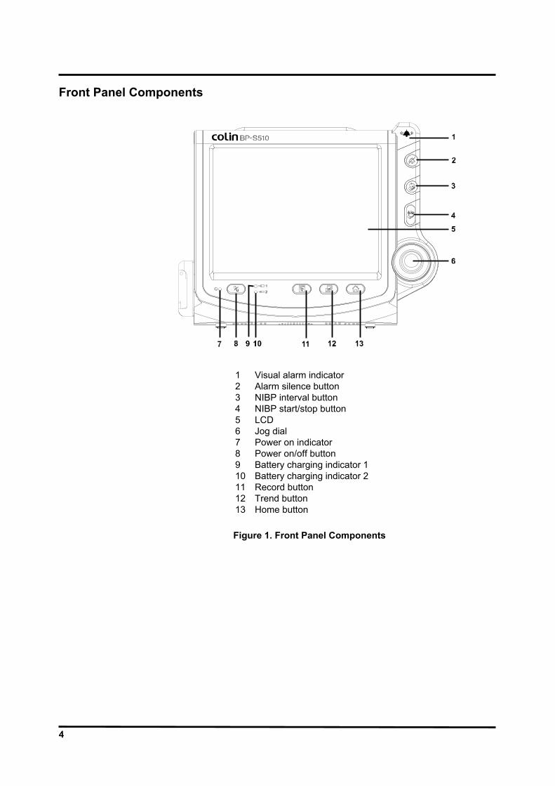
Front Panel Components
1 Visual alarm indicator 2 Alarm silence button 3 NIBP interval button 4 NIBP start/stop button 5 LCD 6 Jog dial 7 Power on indicator 8 Power on/off button 9 Battery charging indicator 1 10 Battery charging indicator 2 11 Record button 12 Trend button 13 Home button Figure 1. Front Panel Components

5
Rear Panel Components
1 Handle 4 Equipotential terminal 2 Ventilators 5 Speaker 3 VESA connector holes
Figure 2. Rear Panel Components

6
Left Panel Components
1 ECG connector 7 NIBP connector 2 Temperature channel 1 8 AC power connector 3 Temperature channel 2 9 Water trap (option) 4 SpO2 connector 10 CO2 connector (option) 5 IBP channel 1 (option) 11 CO2 filter (option) 6 IBP channel 2 (option) 12 CO2 exhaust port (option)
Figure 3. Left Panel Components

7
Right Panel Components
1 USB port 4 Battery cover 2 LAN port 5 Recorder (option) 3 RS-232 port
Figure 4. Right Panel Components

8
This page is intentionally left blank.

9
ROUTINE MAINTENANCE
WARNING: Do not spray or pour any liquid on the monitor or its accessories. Do not immerse the monitor or its accessories in liquid or clean with caustic or abrasive cleaners.
Cleaning
The monitor may be surface-cleaned by using a soft cloth dampened with either a commercial, nonabrasive cleaner or one of the solution listed in the below. Lightly wipe the top, bottom and front surfaces of the monitor lightly.
70% Isopropyl alcohol 10% Chlorine bleach solution
For cables, sensors, cuffs, transducer and probes, follow cleaning instructions in the directions for use shipped with those components. Avoid spilling liquid on the monitor, especially in connector areas. If liquid is accidentally spilled on the monitor, clean and dry thoroughly before reuse. If in doubt about monitor safety, refer the unit to qualified service personnel for checking.
Periodic Safety and Functional Checks
The following performance verification tests may be used following repair or during routine maintenance (if required by your local institution). The following checks should be performed at least every year by qualified service personnel.
1. Inspect labels for legibility. If the labels are not legible, contact your local supplier.
2. If the monitor has been visibly damaged or subjected to mechanical shock (for example, if dropped), perform the performance tests as described in Performance Verification section. If the unit fails these performance tests, refer to Troubleshooting section.
3. Perform the electrical safety tests described in Performance Verification section. If the unit fails these electrical safety tests, do not attempt to repair. Contact your local supplier.
4. Inspect the fuses for proper value and rating. qty 2, 6.3 A, 250 volts for AC mains

10
Batteries
If the monitor has not been used for a long period of time, more than 2 months, the battery will need charging. To charge the battery, connect the monitor to an AC outlet as described in Battery Charge paragraph in this service manual or the Battery Operation section of the operator’s manual. Note: Storing the monitor for a long period without charging the battery may degrade the
battery capacity. The battery may require a full charge/discharge cycle to restore normal capacity. Omron Healthcare recommends that the monitor’s sealed, Ni-MH batteries be replaced at 2 year intervals. Refer to Disassembly Guide section.
CAUTION: If the monitor is to be stored for a period of 2 months or longer, it is recommended to notify service personnel to remove the battery from the monitor prior to storage. To replace or remove the battery, refer to Disassembly Guide section. Recharging the battery is strongly recommended when the battery has not been recharged for 2 or more months. CAUTION: If the battery shows any signs of damage, leakage, or cracking, it must be replaced immediately. CAUTION: Discarded battery may explode during incineration. Recycle used batteries properly. Do not dispose of batteries in refuse containers.
Environmental Protection
Follow local governing ordinances and recycling plans regarding disposal or recycling batteries and other device components.
Note: The monitor should be disposed of separately from the municipal waste stream via
designated collection facilities appointed by the government or the local authorities. Note: The correct disposal of your old appliance will help prevent potential negative
consequences for the environment and human health. Note: For more detailed information about disposal of your old appliance, please contact
your city office, waste disposal service or the shop where you purchased the monitor.

11
PERFORMANCE VERIFICATION General
This section discusses the tests used to verify performance following repairs or during routine maintenance. All tests can be performed without removing the monitor covers. All tests except the battery charge and battery discharge tests must be performed as the last operation before the monitor is returned to the user. If the monitor fails to perform as specified in any test, repairs must be made to correct the problem before the monitor is returned to the user.
Required Equipment
Table 1 lists the equipment required for performance verifications.
Table 1. Required Equipment Equipment Description Digital multimeter (DMM) Fluke Model 87 or equivalent ECG cable ECG cable No.8 ECG 3 lead wires ECG 3 lead wires No.5 ECG 5 lead wires ECG 5 lead wires No.6 (optional) NIBP cuff for neonatal NIBP cuff No.11 (3cm) NIBP cuff for adult NIBP cuff No.3 (12cm) NIBP cuff hose for neonatal NIBP cuff hose No.3 (3.5m) NIBP cuff hose for adult NIBP cuff hose No.1 (3.5m) NIBP rigid PVC vessel 9 cm diameter NIBP rigid PVC vessel 5 cm diameter SpO2 extension cable DOC-10 SpO2 sensor (durable) DS-100A Temperature probes YSI-400 series IBP extension cable IBP extension cable ECG simulator Metron PS-420 or equivalent SpO2 simulator Nellcor SRC-MAX simulator NIBP simulator Bio-Tek BP Pump 2 or equivalent Sphygmomanometer small Common used sphygmomanometer Y tube Omron Y tube Cuff joint Omron cuff joint Inflation bulb Omron inflation bulb Temperature simulator Metron PS-420 or equivalent IBP simulator Metron PS-420 or equivalent IBP test cable Omron IBP test cable CO2 gas flow meter STEC SEF-21A or equivalent Safety analyzer Metron QA-90 or equivalent Data interface cable RS-232 cable LAN cable Common used LAN cable USB memory Common used USB memory Stopwatch Manual or electronic
Note: The sphygmomanometer small shall be calibrated periodically. The correct value
can not be found if the sphygmomanometer has not been calibrated. Note: Contact your local supplier for pricing and ordering information.

12
System Tests
The monitor must be placed in the service menu. For a detailed explanation to access the service menu, refer to Service Menu and Factory Default Settings section. 1. Rotate the jog dial to select System Test in the service menu, and then press the jog
dial.
Switch/LED Test
This tests the buttons, jog dial and the visual alarm indicator.
Figure 5. Switch/LED Test
1. Select Switch/LED Test in the system test. The image screen will appear as Figure
5. 2. Verify that the alarm visual indicator flashes with red and yellow. 3. Press all the buttons one by one, except for the power on/off button.
When a button is pressed, the same button on the image screen will turn blue. For example, when the jog dial is pressed, the jog dial on the screen turns blue. When the jog dial is rotated, the sign indicating the rotate direction will appear.
4. After finishing the test, press the jog dial twice to exit.
Pass/Fail Results If a pressed button turns blue on the screen, the button is in a normal state.

13
LCD Test This tests the LCD display. 1. Select LCD Test in the system test. 2. The screen color will change over the following sequence:
Red Green Blue White Black … every two seconds 3. After testing the test, press jog dial twice to exit. Pass/Fail Results When the color of the test screen changes in the order from Red, Green, Blue, White to Black, the LCD display is in a normal state.
Alarm Audible Test
This tests the alarm tones by displaying the level of the alarm tone on the screen.
Figure 6. Alarm Audible Test
1. Select Alarm Audible Test in the system test. 2. The level of the alarm tone will appear on the screen as the alarm tone sounds. Then,
the level goes up gradually. When the tone reaches the maximum level 8, it returns to the minimum level 1.
3. After finishing the test, press the jog dial to select Cancel. The menu box will disappear.
Pass/Fail Results When the alarm tone changes to eight steps, the alarm tone is in a normal state.

14
Tone Audible Test
This tests HR/PR tones, key beeps and completion sounds.
Figure 7. Tone Audible Test
1. Select Tone Audible Test in the system test. 2. Rotate the jog dial to select HR/PR Tone.
The HR/PR tone sounds intermittently as the level goes up gradually. When the tone reaches the maximum level 7, it returns to the minimum 1. When the tone returns to the minimum, the pitch will change automatically. There are three pitches – High, Med and Low.
3. Press Cancel to finish the test. 4. Rotate the jog dial to select Key Beep or Completion Sound. 5. Verify that Key Beep or Completion sound sounds properly. 6. After finishing the test, press the jog dial to select Cancel. The menu box will
disappear. Pass/Fail Results When the HR/PR tone changes to seven steps and the pitch changes to three steps, the HR/PR tone is normally set. When the key beep changes to seven steps, the key beep is normally set. When the completion sound is heard, it is normally set.

15
Recorder Test
This tests the printing condition.
Figure 8. Recorder Test
1. Select Recorder Test in the system test.
The recorder condition is displayed as follows: Paper: The “ Mounted” sign appears when the paper is installed properly. If the paper runs out or the printer door is open, “empty” sign will appear in red. Head Temperature: The “OK” sign appears when the head temperature is normal. If the head temperature is abnormal, the ”error” sign appears. Vp Voltage: The “OK” sign appears when the voltage is normal. If the voltage is abnormal, the “error” sign appears.
2. Select Grid Print. Verify that printing can be done without meandering. 3. After checking, select Cancel to stop printing. 4. Select Contact Print. Verify that printing can be done at an equal density. 5. After checking, select Cancel to stop printing. Pass/Fail Results When the printed line is free from meandering on unevenness in density, the printing function is normal.

16
Backup RAM Clear
When Backup RAM Clear is set to Yes, all settings of the monitor including the service settings return to the factory defaults from the next cycle.
Figure 9. Backup RAM Clear
Note: Set the monitor to appropriate AC line frequency (50Hz or 60Hz) again after Back
Up RAM clearance.
17
Performance Tests
The battery charge and battery discharge test should be performed before monitor repairs whenever the battery is suspected as being a source of the problems. All other tests may be used following repairs or during routine maintenance (if required by your local institution). Before performing the battery discharge test, ensure that the battery is fully charged. This section is written using factory defaults as power-up. If your institution has preconfigured custom defaults, those values will be displayed.
Power
1. Connect the monitor to AC power source using proper power cord.
2. Verify that Battery charging indicator is lit.
3. Press Power on/off button.
4. Verify that the monitor is turned on and that Power on indicator is lit.
5. After the monitor operates in normal mode, disconnect the power cord.
6. Verify that Battery status icon appears on the screen instead of lighting Battery charging indicator.
7. Press Power on/off button over 1 second, and then verify that the monitor is turned off. Battery Charge
1. Connect the monitor to AC power source using proper power cord.
2. Verify that Battery charging indicator is lit with orange.
3. Charge the battery fully until Battery charging indicator 1 and 2 are changed to green. It will be take about 12 hours.
4. To check for a full charge, perform the procedure in paragraph “Battery Discharge”. Note: The battery may require a complete charge/discharge cycle to restore its normal
capacity, depending on its previous usage. Battery Discharge
1. Disconnect the power cord from the monitor with a fully charge battery.
2. Turn on the monitor by pressing Power on/off button.
3. Verify that Battery status icon appears at bottom of the screen after power-on self-test is completed. The bar in battery status icon should be filled, indicating battery is charged.
4. Connect the SpO2 simulator to monitor via the SpO2 extension cable.
5. Connect the NIBP simulator to the monitor via NIBP cuff hose.
6. Set the SpO2 simulator as follows: SpO2 of 95% and pulse rate of 60bpm.
7. Set the NIBP simulator to simulate pressure setting of 120/80 mmHg and heart rate of 80 bpm.
8. Set NIBP auto mode interval to 5 minutes.
9. The monitor must operate for 1 hour with a fully charged battery. The monitor must operate for at least 15 minutes before the monitor powers down due to the low battery condition.
10. Verify that the low priority alarm occurs and the alarm message “System: Low battery” is displayed about 15 minutes before battery fully discharges.
18
11. Allow monitor to operate until it automatically powers down due to the low battery condition. Verify that the high priority alarm occurs and the alarm message “System: Critically low-battery condition” is displayed about 5 minutes before the monitor automatically shuts down.
12. If the monitor passes this test, immediately recharge the battery. (paragraph “Battery Charge”)
Power-On Self-Test (POST)
1. Connect the monitor to AC power source and verify that Battery charging indicator is lit.
2. Observe the monitor’s LCD screen. With the monitor off, press Power on/off button. The monitor must perform the following sequence.
a. The monitor progresses the checksum for the flash memory and displays the bar while the checksum is proceeding.
b. After the checksum for flash memory is completed, the copyright screen appears and all indicators are lit for a few seconds. The copyright screen displays the company logo, the version of system and the current time.
c. Then the monitor performs the power-on self-test (POST).
d. Upon successful completion of power-on self-test (POST), the post pass tone sounds and the monitor will be in normal monitoring screen.
Note: Power-on self-test (POST) including the checksum for the flash memory takes approximately 13 seconds to complete.
Note: If an error condition occurs during the POST, the monitor will be display an error
message. Note: During the POST, the integrity of all programming is checked first. If software testing
is successful, hardware tests are initiated. If all testing is successful, the monitor is ready for use. If an error message is displayed during the POST, please refer to Troubleshooting section.
19
General Operation Tests Alarms and Alarm Silence
1. Connect the monitor to an AC power source.
2. Press Power on/off button to turn on the monitor.
3. Connect the SpO2 simulator to the SpO2 extension cable and connect the cable to the monitor.
4. Set the SpO2 simulator as follows: SpO2 of 75% and pulse rate of 60bpm.
5. Verify following the monitor reaction:
a. The pulse amplitude indicator begins to track artificial pulse signal from the SpO2 simulator.
b. After about 10 to 20 seconds, the monitor displays oxygen saturation and pulse rate as specified by simulator. Verify values are within following tolerances:
Tolerance of Oxygen Saturation : ±2 % Tolerance of Pulse Rate : ±3 bpm
c. Audible alarm sounds and “SpO2: Lower limit violated” message will be displayed and %SpO2 numerical area will flash, indicating the parameter has violated default alarm limits. (High priority alarm)
6. Press Alarm silence button on the monitor’s front panel. Audible alarm will be temporarily silenced.
7. Verify the following:
a. An audible alarm remains silenced.
b. Alarm silence icon appears in SpO2 numerical area on the screen.
c. %SpO2 display continues flashing.
d. Audible alarm returns in approximately 120 seconds. HR/PR Tone Volume Control
1. Press Power on/off button to turn on the monitor.
2. Connect the SpO2 simulator to SpO2 extension cable and connect the cable to the monitor.
3. Set the SpO2 simulator as follows: SpO2 of 75% and pulse rate of 60bpm.
4. Verify %SpO2 and pulse rate values are correctly displayed.
5. Press Alarm silence button on front panel of the monitor to temporarily silence audible alarm.
6. Select Setup icon to display Setup menu.
7. Select HR/PR tone Volume in Setup menu.
8. Set HR/PR tone volume level 1 to level 7 and return to the monitoring screen. Verify beeping pulse rate tone increases.
9. Set HR/PR tone volume level 7 to level 1 and return to the monitoring screen. Verify beeping pulse rate tone decreases.

20
10. Set HR/PR tone volume to Off and return to the monitoring screen. Verify beeping pulse rate tone is no longer audible.
11. Return HR/PR tone volume to a comfortable level.
Sensor LED Excitation Test
This procedure uses normal system components to test circuit operation. An SpO2 sensor, DS-100A is used to examine LED intensity control. The red LED is used to verify intensity modulation caused by the LED intensity control circuit. 1. Connect the monitor to an AC power source.
2. Press the Power on/off button to turn on the monitor.
3. Connect the SpO2 extension cable to the monitor.
4. Connect the SpO2 sensor to the SpO2 extension cable.
5. Leave the sensor open with the LEDs and photo detector visible.
6. After the monitor completes its normal power-up sequence, verify that the sensor LED is brightly lit.
7. Slowly move sensor LED in proximity of photodetector element of the sensor (close the sensor slowly). Verify; as LED approaches the optical sensor, that the LED intensity decreases.
8. Open the sensor and notice that the LED intensity increases.
9. Repeat step 7 and intensity will again decrease. This variation is an indication that the microprocessor is in proper control of LED intensity.
10. Press Power on/off button to turn off the monitor.
Restoring Power-On Default Settings
The following test procedures will verify that alarms are activated at the level of factory default alarm limits and that any changed settings are saved and in effect when the user changes alarm limit settings and saves the current settings as a power default.
Table 2. Parameter Alarm Limit Factory Defaults Factory Defaults Adult Neonatal
HR/PR Upper Alarm Limits 180 bpm (beats per minute) 200 bpm HR/PR Lower Alarm Limits 40 bpm 50 bpm NIBP SYS Upper Alarm Limits 200mmHg 130 mmHg NIBP SYS Lower Alarm Limits 70 mmHg 50 mmHg NIBP DIA Upper Alarm Limits 160 mmHg 100 mmHg NIBP DIA Lower Alarm Limits 30 mmHg 10 mmHg NIBP MAP Upper Alarm Limits 180 mmHg 110 mmHg NIBP MAP Lower Alarm Limits 40 mmHg 20 mmHg %SpO2 Upper Alarm Limits 100 % 100 % %SpO2 Lower Alarm Limits 90 % 85 % RESP Upper Alarm Limits 30 bpm (breaths per minute) 50 bpm RESP Lower Alarm Limits 0 bpm 0 bpm TEMP1, 2 Upper Alarm Limits 38.0°C (100.4°F) 39.0°C (102.2°F) TEMP1, 2 Lower Alarm Limits 14.5°C (58.1°F) 14.5°C (58.1°F) EtCO2 Upper Alarm Limits 80mmHg 80mmHg EtCO2 Lower Alarm Limits 0mmHg 0mmHg InCO2 Upper Alarm Limits 20mmHg 20mmHg

21
Factory Defaults Adult Neonatal InCO2 Lower Alarm Limits 0mmHg 0mmHg IBP1 SYS Upper Alarm Limits 200 mmHg 130 mmHg IBP1 SYS Lower Alarm Limits 70 mmHg 50 mmHg IBP1 DIA Upper Alarm Limits 160 mmHg 100 mmHg IBP1 DIA Lower Alarm Limits 30 mmHg 10 mmHg IBP1 MEAN Upper Alarm Limits 180 mmHg 110 mmHg IBP1 MEAN Lower Alarm Limits 40 mmHg 20 mmHg IBP2 SYS Upper Alarm Limits 200 mmHg 130 mmHg IBP2 SYS Lower Alarm Limits 70 mmHg 50 mmHg IBP2 DIA Upper Alarm Limits 160 mmHg 100 mmHg IBP2 DIA Lower Alarm Limits 30 mmHg 10mmHg IBP2 MEAN Upper Alarm Limits 180 mmHg 110 mmHg IBP2 MEAN Lower Alarm Limits 40 mmHg 20 mmHg
1. Turn on the monitor at the factory default settings.
2. Select Alarm limits icon to display Alarm limits menu.
3. Verify that alarm limits are set to as shown in Table 2.
4. Change Patient mode in the setup menu Adult to Neonatal, then verify that alarm limits are set to as shown in Table 2.
5. Change alarm limit value via Alarm limits menu.
6. Save the changed alarm limit values as a power on default setting via Service menu (see Service Menu and Factory Defaults section). Turn off the monitor.
7. Press Power on/off button to turn on the monitor.
8. Verify alarm limits are set to the changed alarm limit values.
Recorder Test (Option)
If Recorder option is installed in the monitor, the following test procedures will verify the recorder performance. 1. Connect the monitor to an AC power source.
2. Press Power on/off button to turn on the monitor.
3. Connect all necessary simulators to the monitor.
4. Select Setup icon on the screen to display Setup menu.
5. Test #1: 20 sec printing
a. Set Wave record time to 20 sec via setup menu.
b. Press Record button when all the parameter signals display normally.
c. Verify that the parameter values and waveforms are printed out for 20 seconds.
6. Test #2: Continuous printing
a. Set Wave record time to Continuous via setup menu
b. Press Record button when all the parameter signals display normally.
c. Verify the parameter values and waveforms are printed out continuously.
d. Verify printing stops with pressing Record button again.
22
7. Test #3: Record speed
a. Set Record speed to 25 mm/s.
b. Press Record button when all the parameter signals display normally.
c. Verify the parameter values and waveforms are printed out with 25 mm/s.
d. Set Record speed to 50 mm/s.
e. Press Record button when all the parameter signals display normally.
f. Verify that the parameter values and waveforms are printed out with 50 mm/s.
8. Test #4: Wave Record Select
a. Set Wave Record Select to ECG1+ECG2 via Setup menu.
b. Press Record button when all the parameter signals display normally.
c. Verify the two ECG waveforms are printed out.
d. Repeat this test for other selections.
9. Test #5: Record on Alarm
a. Set Record on Alarm to ON via Setup menu.
b. Set Heart rate of ECG simulator to 30 bpm.
c. Verify “HR: Lower limit violated” alarm is activated and the parameter values and waveforms are printed out.
10. Test#6: Auto List Record
a. Set Auto list record to ON via Setup menu.
b. Set Save time interval to 0.5 minutes via Tabular trend menu.
c. Verify that the monitor automatically prints out the data after stored 8 data in the trend memory.
Note: If no recorder is installed in the monitor, the record setup menus will be grayed out
in Setup menu.
Note: If there is no recorder paper left or recorder paper places improperly, the monitor will display an informative message.
Serial Interface Test
Perform the following procedure to test the serial port. The serial connector DSub-15, located on the monitor’s right panel, identified with the data interface symbol (RS-232). 1. Turn on the monitor, and select the service menu via the setup menu.
2. Enter the service code, 6, 1, 6, in order.
3. Connect the serial interface cable between the monitor and PC COM1 port.
4. Run “BP-S510_Comm_Test.exe” on PC.
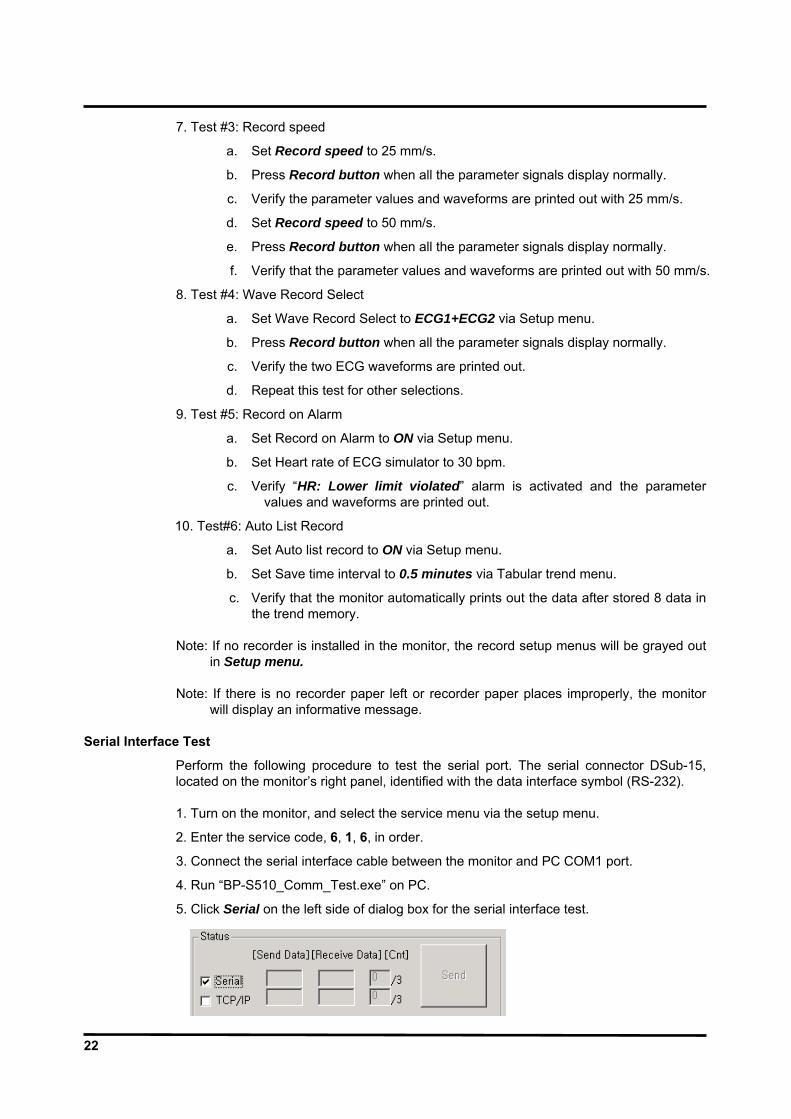
5. Click Serial on the left side of dialog box for the serial interface test.

23
6. Click Connect, then verify that log message “RS232C [Com1] Connected” appears on the PC.
7. Click Send, then verify the followings:
- The monitor displays three dashes (-) with the beep sound.
- The log message “RS232 Test OK!!!” appears on the PC.
8. Click Disconnect to stop the serial interface test.

24
Network Test
Perform the following procedure to test the Network. The Network connector is located on the monitor’s right panel, identified with the Network symbol. Prior to the network test, configure the network setting on PC with the followings. - IP address 192.168.124.1.
- Gateway 192.168. 124. 254.
- Subnet Mask 255.255.255.0.
When completed the network setting on the PC properly, follow the below test procedure.
1. Turn on the monitor, and select the service menu via the setup menu.
2. Enter the service code, 6, 1, 6, in order.
3. Connect a network line to the monitor. (Do not connect PC to the monitor directly)
4. Run “BP-S510_Comm_Test.exe” on PC.
5. Click TCP/IP on the left side of the dialog box for the network test.
6. Click Connect, then verify that log message “TCP/IP [192.168.124.2] Connected” appears on the PC.
25
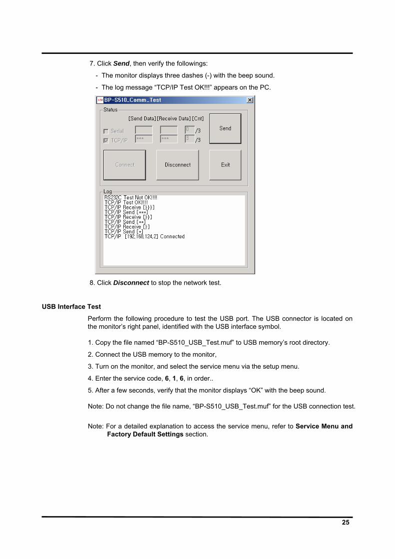
7. Click Send, then verify the followings:
- The monitor displays three dashes (-) with the beep sound.
- The log message “TCP/IP Test OK!!!” appears on the PC.
8. Click Disconnect to stop the network test.
USB Interface Test
Perform the following procedure to test the USB port. The USB connector is located on the monitor’s right panel, identified with the USB interface symbol. 1. Copy the file named “BP-S510_USB_Test.muf” to USB memory’s root directory.
2. Connect the USB memory to the monitor,
3. Turn on the monitor, and select the service menu via the setup menu.
4. Enter the service code, 6, 1, 6, in order..
5. After a few seconds, verify that the monitor displays “OK” with the beep sound. Note: Do not change the file name, “BP-S510_USB_Test.muf” for the USB connection test.
Note: For a detailed explanation to access the service menu, refer to Service Menu and Factory Default Settings section.
26
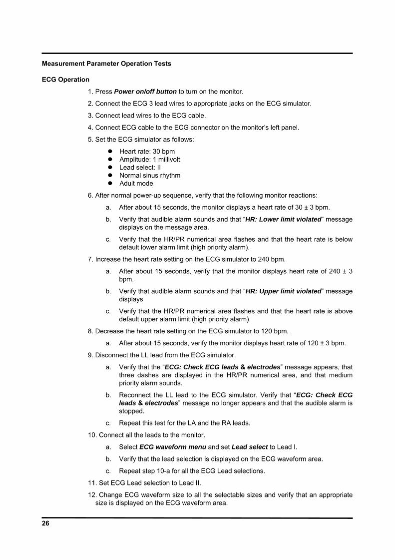
Measurement Parameter Operation Tests ECG Operation
1. Press Power on/off button to turn on the monitor.
2. Connect the ECG 3 lead wires to appropriate jacks on the ECG simulator.
3. Connect lead wires to the ECG cable.
4. Connect ECG cable to the ECG connector on the monitor’s left panel.
5. Set the ECG simulator as follows:
Heart rate: 30 bpm Amplitude: 1 millivolt Lead select: II Normal sinus rhythm Adult mode
6. After normal power-up sequence, verify that the following monitor reactions:
a. After about 15 seconds, the monitor displays a heart rate of 30 ± 3 bpm.
b. Verify that audible alarm sounds and that “HR: Lower limit violated” message displays on the message area.
c. Verify that the HR/PR numerical area flashes and that the heart rate is below default lower alarm limit (high priority alarm).
7. Increase the heart rate setting on the ECG simulator to 240 bpm.
a. After about 15 seconds, verify that the monitor displays heart rate of 240 ± 3 bpm.
b. Verify that audible alarm sounds and that “HR: Upper limit violated” message displays
c. Verify that the HR/PR numerical area flashes and that the heart rate is above default upper alarm limit (high priority alarm).
8. Decrease the heart rate setting on the ECG simulator to 120 bpm.
a. After about 15 seconds, verify the monitor displays heart rate of 120 ± 3 bpm.
9. Disconnect the LL lead from the ECG simulator.
a. Verify that the “ECG: Check ECG leads & electrodes” message appears, that three dashes are displayed in the HR/PR numerical area, and that medium priority alarm sounds.
b. Reconnect the LL lead to the ECG simulator. Verify that “ECG: Check ECG leads & electrodes” message no longer appears and that the audible alarm is stopped.
c. Repeat this test for the LA and the RA leads.
10. Connect all the leads to the monitor.
a. Select ECG waveform menu and set Lead select to Lead I.
b. Verify that the lead selection is displayed on the ECG waveform area.
c. Repeat step 10-a for all the ECG Lead selections.
11. Set ECG Lead selection to Lead II.
12. Change ECG waveform size to all the selectable sizes and verify that an appropriate size is displayed on the ECG waveform area.

27
13. Set the ECG cable select to Auto via ECG waveform menu.
14. Verify that Lead Select in ECG waveform menu displays I, II, III.
15. Disconnect 3 ECG leads and connect 5 ECG leads.
16. Verify that Lead Select in ECG waveform menu displays I, II, III. aVR, aVL, aVF, V (Chest Lead).
17. Repeat step 9 to 12.
18. Turn off the monitor. Note: The accuracy of the monitor ECG measurements is ±3 bpm. In the procedure, add
the tolerance of the simulator to the acceptable range of readings.

28
NIBP Operation
The monitor must be placed in the service menu. For a detailed explanation to access the service menu, refer to Service Menu and Factory Default Settings section. 1. Rotate the jog dial to select NIBP Test in the service menu, and then press the jog
dial. Note: Inflation Speed Test, Initial Deflation Test (I), Initial Deflation Test (II), Deflation
Speed Test and Offset Test are intended for factory use only. Pressure Sensor Accuracy Test
Figure 10. Pressure Sensor Accuracy Test
1. Connect the NIBP cuff hose to the NIBP connector on the monitor’s left panel.
2. Connect the other end of the NIBP cuff hose to the Y tube via the cuff joint.
3. Connect the sphygmomanometer and the Inflation bulb to the Y tube.
4. Select Pressure Sensor Accuracy Test, and then press the jog dial.
5. Raise the pressure of the sphygmomanometer to 0, 50, 100 and 200 mmHg by pumping the inflation bulb and compare the pressure of the sphygmomanometer with the pressure displayed by the monitor.
If air leakage disables accurate comparison of the above pressures, eliminate the cause of air leakage.
6. After finishing the test, press the jog dial to select Cancel. The menu box will disappear. If Cancel is selected during the test progressing, the test will stop and the menu box will disappear.
Pass/Fail Results The difference between the sphygmomanometer’s and the monitor’s readings are as follows:
Sphygmomanometer Monitor’s Readings 0 mmHg ±0 mmHg 50 mmHg 50±6 mmHg 100 mmHg 100±6 mmHg 200 mmHg 200±6 mmHg

29
Air Leakage Test
Figure 11. Air Leakage Test
1. Place the adult cuff with a rigid PVC vessel (5 cm diameter).
2. Connect the cuff to the NIBP connector on the monitor’s left panel via NIBP cuff hose.
3. Select Air Leakage Test, and then press the jog dial.
4. The result will be displayed in four minutes.
5. After finishing the test, press the jog dial to select Cancel. The menu box will disappear. If Cancel is selected during the test progressing, the test will stop and the menu box will disappear.
Pass/Fail Results It passes if the leak value is less than 12mmHg/3minutes.
30
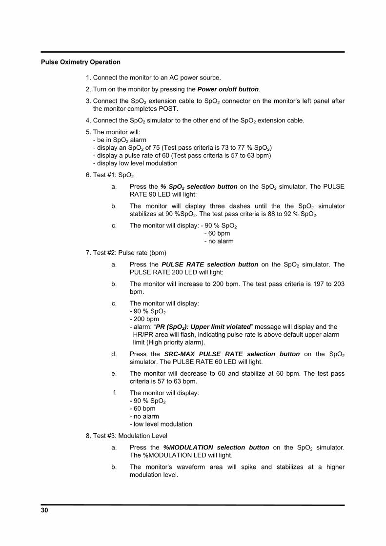
Pulse Oximetry Operation
1. Connect the monitor to an AC power source.
2. Turn on the monitor by pressing the Power on/off button.
3. Connect the SpO2 extension cable to SpO2 connector on the monitor’s left panel after the monitor completes POST.
4. Connect the SpO2 simulator to the other end of the SpO2 extension cable.
5. The monitor will: - be in SpO2 alarm - display an SpO2 of 75 (Test pass criteria is 73 to 77 % SpO2) - display a pulse rate of 60 (Test pass criteria is 57 to 63 bpm) - display low level modulation
6. Test #1: SpO2
a. Press the % SpO2 selection button on the SpO2 simulator. The PULSE RATE 90 LED will light:
b. The monitor will display three dashes until the the SpO2 simulator stabilizes at 90 %SpO2. The test pass criteria is 88 to 92 % SpO2.
c. The monitor will display: - 90 % SpO2 - 60 bpm - no alarm
7. Test #2: Pulse rate (bpm)
a. Press the PULSE RATE selection button on the SpO2 simulator. The PULSE RATE 200 LED will light:
b. The monitor will increase to 200 bpm. The test pass criteria is 197 to 203 bpm.
c. The monitor will display: - 90 % SpO2 - 200 bpm - alarm: “PR (SpO2): Upper limit violated” message will display and the HR/PR area will flash, indicating pulse rate is above default upper alarm limit (High priority alarm).
d. Press the SRC-MAX PULSE RATE selection button on the SpO2 simulator. The PULSE RATE 60 LED will light.
e. The monitor will decrease to 60 and stabilize at 60 bpm. The test pass criteria is 57 to 63 bpm.
f. The monitor will display: - 90 % SpO2 - 60 bpm - no alarm - low level modulation
8. Test #3: Modulation Level
a. Press the %MODULATION selection button on the SpO2 simulator. The %MODULATION LED will light.
b. The monitor’s waveform area will spike and stabilizes at a higher modulation level.

31
c. he monitor will display: - 90 % SpO2 - 60 bpm - no alarm
d. Disconnect all equipments and turn off the monitor.
Respiration Operation
1. Press Power on/off button to turn on the monitor.
2. Connect ECG lead wires to an appropriate jack on the respiration simulator.
3. Connect ECG lead wires to the ECG cable.
4. Connect the ECG cable to the ECG connector on the monitor’s left panel.
5. Set the respiration simulator to 120 breaths per minute.
6. After the normal power-up sequence, verify the following reactions:
a. The monitor displays respiration rate of 120 ±3 breaths per minute.
b. Audible alarm will sound, “Resp: Upper limit violated” message will display and the Respiration numerical area will flash, indicating a respiration rate is above default upper alarm limits. (high priority alarm)
7. Decrease the respiration rate setting on the respiration simulator to 20 breaths per minute.
a. Verify that the monitor displays the respiration rate of 20 ±3 breaths per minute.
Note: The accuracy of Respiration measurements is ±3 breaths per minute. In the
procedure below, add the tolerance of the simulator to the acceptable range of readings.
Temperature Operation
1. Press Power on/off button to turn on the monitor.
2. Connect the temperature probe (supplied with the temperature simulator) to an appropriate jack on the temperature simulator.
3. Connect the temperature probe to the temperature connector on the monitor’s left panel.
4. Set the temperature simulator as follows:
Temperature: 37°C (98.0°F) Probe type: YSI-400 series Temperature Probes (Probe accuracy: ±0.1°C)
5. After the normal power-up sequence, verify that the temperature reads 37°C ±0.1°C (98.6°F ±0.2°F if Fahrenheit is selected for the temperature unit).
6. Turn off the monitor.
Note: The accuracy of temperature measurements is ±0.1°C (±0.2°F) in the range of
25°C to 45°C and ±0.2°C in the range of 15° C to less than 25° C. In the procedure above, add the tolerance of the simulator and the probe to the acceptable range of readings.
32
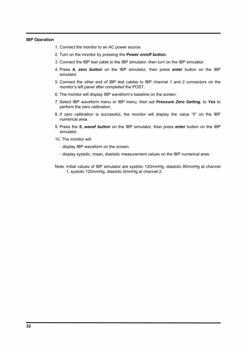
IBP Operation
1. Connect the monitor to an AC power source.
2. Turn on the monitor by pressing the Power on/off button.
3. Connect the IBP test cable to the IBP simulator, then turn on the IBP simulator.
4. Press 6, zero button on the IBP simulator, then press enter button on the IBP simulator.
5. Connect the other end of IBP test cables to IBP channel 1 and 2 connectors on the monitor’s left panel after completed the POST.
6. The monitor will display IBP waveform’s baseline on the screen.
7. Select IBP waveform menu or IBP menu, then set Pressure Zero Setting, to Yes to perform the zero calibration.
8. If zero calibration is successful, the monitor will display the value “0” on the IBP numerical area.
9. Press the 5, wavef button on the IBP simulator, then press enter button on the IBP simulator.
10. The monitor will:
‐ display IBP waveform on the screen.
‐ display systolic, mean, diastolic measurement values on the IBP numerical area.
Note: Initial values of IBP simulator are systolic 120mmHg, diastolic 80mmHg at channel
1, systolic 120mmHg, diastolic 0mmHg at channel 2.

33
CO2 Operation
2. Connect the monitor to an AC power source. Turn on the monitor.
3. Rotate the jog dial to highlight CO2 numerical area and then press the jog dial to display the CO2 menu.
4. Verifying that Capno Measurement is set to On in CO2 menu.
5. Test #1: Display Accuracy
a. Connect the 10% calibration gas cylinder with the valve to the sampling tube connected to the water trap of the monitor.
b. After passed the warm up time (about 3 minutes), repeat 3 or 4 times turning on and off the valve of the gas cylinder with the interval of 1 to 2 seconds.
c. Verifying that the monitor displays 76mmHg ± 2mmHg in CO2 numerical area.
6. Test #2: Flow Rate
a. Connect the flow meter to the sampling tube connected to the monitor.
b. Connect a sampling tube to the other side of the flow meter and make the other side of the sampling tube open.
c. Verify that the flow rate is between 150 ± 2mmHg.
7. Test #3: Water Trap
a. Check that the module does not indicate a "Water trap full" message when a clean water trap is installed. If this is correct, remove the water bottle and block the path between the water trap LED and detector.
b. Verify that a "water trap full" message appears.
8. Test #4: Occlusion
a. Block the sample input. The module should enter the "occlusion" state. Verify that it does correctly enter this occlusion state.
b. Unblock the input. Verify that after the modules occlusion sequence of high flow rates and valve actuations the occlusion message disappears and the module restores normal function.
34
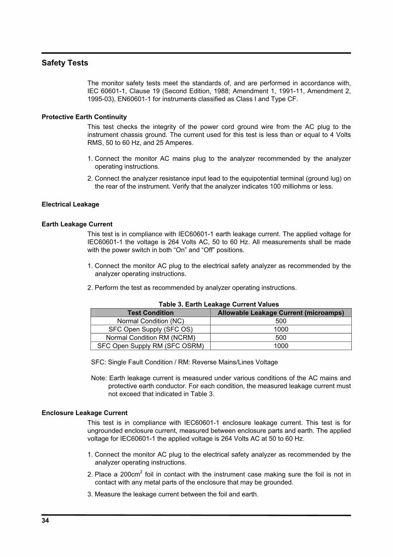
Safety Tests
The monitor safety tests meet the standards of, and are performed in accordance with, IEC 60601-1, Clause 19 (Second Edition, 1988; Amendment 1, 1991-11, Amendment 2, 1995-03), EN60601-1 for instruments classified as Class I and Type CF.
Protective Earth Continuity This test checks the integrity of the power cord ground wire from the AC plug to the instrument chassis ground. The current used for this test is less than or equal to 4 Volts RMS, 50 to 60 Hz, and 25 Amperes. 1. Connect the monitor AC mains plug to the analyzer recommended by the analyzer
operating instructions.
2. Connect the analyzer resistance input lead to the equipotential terminal (ground lug) on the rear of the instrument. Verify that the analyzer indicates 100 milliohms or less.
Electrical Leakage Earth Leakage Current
This test is in compliance with IEC60601-1 earth leakage current. The applied voltage for IEC60601-1 the voltage is 264 Volts AC, 50 to 60 Hz. All measurements shall be made with the power switch in both “On” and “Off” positions. 1. Connect the monitor AC plug to the electrical safety analyzer as recommended by the
analyzer operating instructions.
2. Perform the test as recommended by analyzer operating instructions.
Table 3. Earth Leakage Current Values Test Condition Allowable Leakage Current (microamps)
Normal Condition (NC) 500 SFC Open Supply (SFC OS) 1000
Normal Condition RM (NCRM) 500 SFC Open Supply RM (SFC OSRM) 1000
SFC: Single Fault Condition / RM: Reverse Mains/Lines Voltage Note: Earth leakage current is measured under various conditions of the AC mains and
protective earth conductor. For each condition, the measured leakage current must not exceed that indicated in Table 3.
Enclosure Leakage Current
This test is in compliance with IEC60601-1 enclosure leakage current. This test is for ungrounded enclosure current, measured between enclosure parts and earth. The applied voltage for IEC60601-1 the applied voltage is 264 Volts AC at 50 to 60 Hz. 1. Connect the monitor AC plug to the electrical safety analyzer as recommended by the
analyzer operating instructions.
2. Place a 200cm2 foil in contact with the instrument case making sure the foil is not in contact with any metal parts of the enclosure that may be grounded.
3. Measure the leakage current between the foil and earth.
35
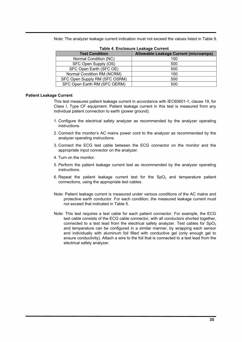
Note: The analyzer leakage current indication must not exceed the values listed in Table 9.
Table 4. Enclosure Leakage Current Test Condition Allowable Leakage Current (microamps)
Normal Condition (NC) 100 SFC Open Supply (OS) 500
SFC Open Earth (SFC OE) 500 Normal Condition RM (NCRM) 100
SFC Open Supply RM (SFC OSRM) 500 SFC Open Earth RM (SFC OERM) 500
Patient Leakage Current
This test measures patient leakage current in accordance with IEC60601-1, clause 19, for Class I, Type CF equipment. Patient leakage current in this test is measured from any individual patient connection to earth (power ground). 1. Configure the electrical safety analyzer as recommended by the analyzer operating
instructions.
2. Connect the monitor’s AC mains power cord to the analyzer as recommended by the analyzer operating instructions.
3. Connect the ECG test cable between the ECG connector on the monitor and the appropriate input connector on the analyzer.
4. Turn on the monitor.
5. Perform the patient leakage current test as recommended by the analyzer operating instructions.
6. Repeat the patient leakage current test for the SpO2 and temperature patient connections, using the appropriate test cables.
Note: Patient leakage current is measured under various conditions of the AC mains and
protective earth conductor. For each condition, the measured leakage current must not exceed that indicated in Table 5.
Note: This test requires a test cable for each patient connector. For example, the ECG
test cable consists of the ECG cable connector, with all conductors shorted together, connected to a test lead from the electrical safety analyzer. Test cables for SpO2 and temperature can be configured in a similar manner, by wrapping each sensor end individually with aluminum foil filled with conductive gel (only enough gel to ensure conductivity). Attach a wire to the foil that is connected to a test lead from the electrical safety analyzer.

36
Table 5. Patient Leakage Current Values Test Condition Allowable Leakage Current (microamps)
Normal Condition (NC) 10 SFC Open Supply (OS) 50
SFC Open Earth (SFC OE) 50 Normal Condition RM (NCRM) 10
SFC Open Supply RM (SFC OSRM) 50 SRC Open Earth RM (SFC OERM) 50
Patient Leakage Current - Mains Voltage on the Applied Part
WARNING: AC mains voltage will be present on the applied part terminals during this test. Exercise caution to avoid electrical shock hazard.
WARNING: Do not touch the patient leads clips or the simulator parts connected to patient leads during this test as an electrical shock will occur.
This test measures patient leakage current in accordance with IEC60601-1, clause 19, for Class I, type CF equipment. In this test, 110% of mains voltage is applied between each patient connection and earth (power ground). Patient leakage current is then measured from any individual patient connection to earth. Note: Keep the patient test cable length as short as possible during the leakage test. Note: This test requires the same test cables for each patient connector as described in
paragraph “Patient Leakage Current”. 1. Configure electrical safety analyzer as recommended by analyzer operating instructions.
2. Connect monitor’s AC mains power cord to analyzer as recommended by analyzer operating instructions.
3. Connect ECG test cable between ECG connector on the monitor and the appropriate input connector on the analyzer.
4. Turn on the monitor.
5. Perform the test as recommended by the analyzer operating instructions.
6. Repeat the test for SpO2 and temperature patient connections, using the appropriate test cables.
Note: Patient leakage current is measured with normal and reverse mains polarity. For
each condition, the measured leakage current must not exceed that indicated in Table 6.
Table 6. Patient Leakage Current Values - Mains Voltage on Applied Part
Test Condition Allowable Leakage Current (microamps) Normal polarity (SFC) 50
Reverse polarity (SFCRM) 50

37
Patient Auxiliary Current
This test measures patient auxiliary current in accordance with IEC60601-1, clause 19, for Class I, type CF equipment. The applied voltage for IEC60601-1 the voltage is 264 volts, 50 to 60 Hz. Patient auxiliary current is measured between each ECG test lead and between each sensor connection for all possible connections. Note: Keep the patient test cable length as short as possible during the leakage test. Note: This test requires the same test cables for each patient connector as described in
paragraph “Patient Leakage Current”. 1. Configure the electrical safety analyzer as recommended by the electrical analyzer’s
operating instructions.
2. Connect the monitor’s AC mains power cord to the electrical analyzer as recommended by the electrical analyzer’s operating instructions.
3. Connect the patient test lead combination in Table 7 to the appropriate input connector on the electrical analyzer.
4. Turn on the monitor.
5. Perform patient auxiliary current test per Table 8 as recommended by electrical analyzer’s operating instructions.
6. Repeat the patient auxiliary current test for each test lead combination as listed in Table 7 and measure each patient auxiliary current.
Table 7. Test Lead Combinations
First Test Lead Second Test Lead ECG #1 (LA) ECG #2 (LL) ECG #1 (LA) ECG # 3 (RA) ECG #2 (LL) ECG #3 (RA) ECG #1 (LA) Temperature 1/2 ECG #2 (LL) Temperature 1/2 ECG #3 (RA) Temperature 1/2 ECG #1 (LA) SpO2 ECG #2 (LL) SpO2 ECG #3 (RA) SpO2 ECG #1 (LA) IBP ECG #2 (LL) IBP ECG #3 (RA) IBP
SpO2 IBP Temperature 1/2 IBP Temperature 1/2 SpO2
Table 8. Allowable Leakage Current
Test Condition Allowable Leakage Current (microamps) Normal Condition (NC) 10 SFC Open Supply (OS) 50
SFC Open Earth (SFC OE) 50 Normal Condition RM (NCRM) 10
SFC Open Supply RM (SFC OSRM) 50 SRC Open Earth RM (SFC OERM) 50

38
Verification Check Sheet Record the results of the performance verification on the sheet.
Model Name Serial
No. Date Tester
PERFORMANCE TEST
ITEMS RESULTS REMARKS Power Pass / Fail Battery charge Pass / Fail Battery discharge Pass / Fail Power-on self-test (POST) Pass / Fail Alarms and alarm silence Pass / Fail HR/PR tone volume control Pass / Fail Sensor LED excitation test Pass / Fail Restoring power-on default settings Pass / Fail Recorder test (option) - - 20 sec printing Pass / Fail - Continuous printing Pass / Fail - Record speed Pass / Fail - Wave record select Pass / Fail - Record on alarm Pass / Fail - Auto list record Pass / Fail Serial interface test Pass / Fail Network test Pass / Fail USB interface test Pass / Fail ECG operation -
- 30 ±.3 bpm (High priority alarm condition) Pass / Fail Value: bpm - 240 ±.3 bpm (High priority alarm condition) Pass / Fail Value: bpm - 120±.3 bpm (Normal condition) Pass / Fail Value: bpm - ECG lead off (LL) Pass / Fail - ECG lead off (LA) Pass / Fail
- ECG lead off (RA) Pass / Fail NIBP operation
- Pressure sensor accuracy test 0 ±.0 mmHg Pass / Fail Value: mmHg- Pressure sensor accuracy test 50 ±.6 mmHg - Pressure sensor accuracy test 100 ±.6 mmHg Pass / Fail Value: mmHg- Pressure sensor accuracy test 200 ±.6 mmHg Pass / Fail Value: mmHg- Air leakage test 12mmHg/3minutes Pass / Fail Value: mmHg
Pulse oximetry operation - - SpO2 90 ± 2 % Pass / Fail Value: % - Pulse rate 60 ± 3 bpm Pass / Fail Value: bpm- Modulation level Pass / Fail
Respiration operation Pass / Fail Temperature operation Pass / Fail IBP operation Pass / Fail CO2 operation -
- Display accuracy Pass / Fail - Flow rate Pass / Fail - Water trap Pass / Fail - Occlusion Pass / Fail
SYSTEM TEST Switch/LED test Pass / Fail LCD test Pass / Fail Alarm audible test Pass / Fail Tone audible test Pass / Fail Recorder test Pass / Fail

39
SAFETY TEST TEST CONDITIONS LIMIT (uA) RESULTS REMARKS Earth leakage current (NC) 500 Pass / Fail Value: uA Earth leakage current (SFC OS) 1000 Pass / Fail Value: uA Earth leakage current (NCRM) 500 Pass / Fail Value: uA Earth leakage current (SFC OSRM) 1000 Pass / Fail Value: uA Enclosure leakage current (NC) 100 Pass / Fail Value: uA Enclosure leakage current (OS) 500 Pass / Fail Value: uA Enclosure leakage current (SFC OE) 500 Pass / Fail Value: uA Enclosure leakage current (NCRM) 100 Pass / Fail Value: uA Enclosure leakage current (SFC OSRM) 500 Pass / Fail Value: uA Enclosure leakage current (SFC OERM) 500 Pass / Fail Value: uA Patient leakage current (NC) 10 Pass / Fail Value: uA Patient leakage current (OS) 50 Pass / Fail Value: uA Patient leakage current (SFC OE) 50 Pass / Fail Value: uA Patient leakage current (NCRM) 10 Pass / Fail Value: uA Patient leakage current (SFC OSRM) 50 Pass / Fail Value: uA Patient leakage current (SFC OERM) 50 Pass / Fail Value: uA Mains voltage on applied part (SFC) 50 Pass / Fail Value: uA Mains voltage on applied part (SFCRM) 50 Pass / Fail Value: uA Patient auxiliary current ECG LA-ECG LL (NC) 10 Pass / Fail Value: uA Patient auxiliary current ECG LA-ECG LL (OS) 50 Pass / Fail Value: uA Patient auxiliary current ECG LA-ECG LL (SFC OE) 50 Pass / Fail Value: uA Patient auxiliary current ECG LA-ECG LL (NCRM) 10 Pass / Fail Value: uA Patient auxiliary current ECG LA-ECG LL (SFC OSRM) 50 Pass / Fail Value: uA Patient auxiliary current ECG LA-ECG LL (SFC OERM) 50 Pass / Fail Value: uA Patient auxiliary current ECG LA-ECG RA (NC) 10 Pass / Fail Value: uA Patient auxiliary current ECG LA-ECG RA (OS) 50 Pass / Fail Value: uA Patient auxiliary current ECG LA-ECG RA (SFC OE) 50 Pass / Fail Value: uA Patient auxiliary current ECG LA-ECG RA (NCRM) 10 Pass / Fail Value: uA Patient auxiliary current ECG LA-ECG RA (SFC OSRM) 50 Pass / Fail Value: uA Patient auxiliary current ECG LA-ECG RA (SFC OERM) 50 Pass / Fail Value: uA Patient auxiliary current ECG LL-ECG RA (NC) 10 Pass / Fail Value: uA Patient auxiliary current ECG LL-ECG RA (OS) 50 Pass / Fail Value: uA Patient auxiliary current ECG LL-ECG RA (SFC OE) 50 Pass / Fail Value: uA Patient auxiliary current ECG LL-ECG RA (NCRM) 10 Pass / Fail Value: uA Patient auxiliary current ECG LL-ECG RA (SFC OSRM) 50 Pass / Fail Value: uA Patient auxiliary current ECG LL-ECG RA (SFC OERM) 50 Pass / Fail Value: uA Patient auxiliary current ECG LA-TEMP1 (NC) 10 Pass / Fail Value: uA Patient auxiliary current ECG LA-TEMP1 (OS) 50 Pass / Fail Value: uA Patient auxiliary current ECG LA-TEMP1 (SFC OE) 50 Pass / Fail Value: uA Patient auxiliary current ECG LA-TEMP1 (NCRM) 10 Pass / Fail Value: uA Patient auxiliary current ECG LA-TEMP1 (SFC OSRM) 50 Pass / Fail Value: uA Patient auxiliary current ECG LA-TEMP1 (SFC OERM) 50 Pass / Fail Value: uA Patient auxiliary current ECG LL-TEMP1 (NC) 10 Pass / Fail Value: uA Patient auxiliary current ECG LL-TEMP1 (OS) 50 Pass / Fail Value: uA Patient auxiliary current ECG LL-TEMP1 (SFC OE) 50 Pass / Fail Value: uA Patient auxiliary current ECG LL-TEMP1 (NCRM) 10 Pass / Fail Value: uA Patient auxiliary current ECG LL-TEMP1 (SFC OSRM) 50 Pass / Fail Value: uA Patient auxiliary current ECG LL-TEMP1 (SFC OERM) 50 Pass / Fail Value: uA Patient auxiliary current ECG RA-TEMP1 (NC) 10 Pass / Fail Value: uA Patient auxiliary current ECG RA-TEMP1 (OS) 50 Pass / Fail Value: uA Patient auxiliary current ECG RA-TEMP1 (SFC OE) 50 Pass / Fail Value: uA Patient auxiliary current ECG RA-TEMP1 (NCRM) 10 Pass / Fail Value: uA Patient auxiliary current ECG RA-TEMP1 (SFC OSRM) 50 Pass / Fail Value: uA Patient auxiliary current ECG RA-TEMP1 (SFC OERM) 50 Pass / Fail Value: uA Patient auxiliary current ECG LA-TEMP2 (NC) 10 Pass / Fail Value: uA Patient auxiliary current ECG LA-TEMP2 (OS) 50 Pass / Fail Value: uA Patient auxiliary current ECG LA-TEMP2 (SFC OE) 50 Pass / Fail Value: uA Patient auxiliary current ECG LA-TEMP2 (NCRM) 10 Pass / Fail Value: uA Patient auxiliary current ECG LA-TEMP2 (SFC OSRM) 50 Pass / Fail Value: uA Patient auxiliary current ECG LA-TEMP2 (SFC OERM) 50 Pass / Fail Value: uA Patient auxiliary current ECG RA-TEMP2 (NC) 10 Pass / Fail Value: uA

40
SAFETY TEST TEST CONDITIONS LIMIT (uA) RESULTS REMARKS Patient auxiliary current ECG RA-TEMP2 (OS) 50 Pass / Fail Value: uA Patient auxiliary current ECG RA-TEMP2 (SFC OE) 50 Pass / Fail Value: uA Patient auxiliary current ECG RA-TEMP2 (NCRM) 10 Pass / Fail Value: uA Patient auxiliary current ECG RA-TEMP2 (SFC OSRM) 50 Pass / Fail Value: uA Patient auxiliary current ECG RA-TEMP2 (SFC OERM) 50 Pass / Fail Value: uA Patient auxiliary current ECG LA-SpO2 (NC) 10 Pass / Fail Value: uA Patient auxiliary current ECG LA-SpO2 (OS) 50 Pass / Fail Value: uA Patient auxiliary current ECG LA-SpO2 (SFC OE) 50 Pass / Fail Value: uA Patient auxiliary current ECG LA-SpO2 (NCRM) 10 Pass / Fail Value: uA Patient auxiliary current ECG LA-SpO2 (SFC OSRM) 50 Pass / Fail Value: uA Patient auxiliary current ECG LA-SpO2 (SFC OERM) 50 Pass / Fail Value: uA Patient auxiliary current ECG LL-SpO2 (NC) 10 Pass / Fail Value: uA Patient auxiliary current ECG LL-SpO2 (OS) 50 Pass / Fail Value: uA Patient auxiliary current ECG LL-SpO2 (SFC OE) 50 Pass / Fail Value: uA Patient auxiliary current ECG LL-SpO2 (NCRM) 10 Pass / Fail Value: uA Patient auxiliary current ECG LL-SpO2 (SFC OSRM) 50 Pass / Fail Value: uA Patient auxiliary current ECG LL-SpO2 (SFC OERM) 50 Pass / Fail Value: uA Patient auxiliary current ECG RA-SpO2 (NC) 10 Pass / Fail Value: uA Patient auxiliary current ECG RA-SpO2 (OS) 50 Pass / Fail Value: uA Patient auxiliary current ECG RA-SpO2 (SFC OE) 50 Pass / Fail Value: uA Patient auxiliary current ECG RA-SpO2 (NCRM) 10 Pass / Fail Value: uA Patient auxiliary current ECG RA-SpO2 (SFC OSRM) 50 Pass / Fail Value: uA Patient auxiliary current ECG RA-SpO2 (SFC OERM) 50 Pass / Fail Value: uA Patient auxiliary current ECG LA-IBP1 (NC) 10 Pass / Fail Value: uA Patient auxiliary current ECG LA-IBP1 (OS) 50 Pass / Fail Value: uA Patient auxiliary current ECG LA-IBP1 (SFC OE) 50 Pass / Fail Value: uA Patient auxiliary current ECG LA-IBP1 (NCRM) 10 Pass / Fail Value: uA Patient auxiliary current ECG LA-IBP1 (SFC OSRM) 50 Pass / Fail Value: uA Patient auxiliary current ECG LA-IBP1 (SFC OERM) 50 Pass / Fail Value: uA Patient auxiliary current ECG LL-IBP1 (NC) 10 Pass / Fail Value: uA Patient auxiliary current ECG LL-IBP1 (OS) 50 Pass / Fail Value: uA Patient auxiliary current ECG LL-IBP1 (SFC OE) 50 Pass / Fail Value: uA Patient auxiliary current ECG LL-IBP1 (NCRM) 10 Pass / Fail Value: uA Patient auxiliary current ECG LL-IBP1 (SFC OSRM) 50 Pass / Fail Value: uA Patient auxiliary current ECG LL-IBP1 (SFC OERM) 50 Pass / Fail Value: uA Patient auxiliary current ECG RA-IBP1 (NC) 10 Pass / Fail Value: uA Patient auxiliary current ECG RA-IBP1 (OS) 50 Pass / Fail Value: uA Patient auxiliary current ECG RA-IBP1 (SFC OE) 50 Pass / Fail Value: uA Patient auxiliary current ECG RA-IBP1 (NCRM) 10 Pass / Fail Value: uA Patient auxiliary current ECG RA-IBP1 (SFC OSRM) 50 Pass / Fail Value: uA Patient auxiliary current ECG RA-IBP1 (SFC OERM) 50 Pass / Fail Value: uA Patient auxiliary current ECG LA-IBP2 (NC) 10 Pass / Fail Value: uA Patient auxiliary current ECG LA-IBP2 (OS) 50 Pass / Fail Value: uA Patient auxiliary current ECG LA-IBP2 (SFC OE) 50 Pass / Fail Value: uA Patient auxiliary current ECG LA-IBP2 (NCRM) 10 Pass / Fail Value: uA Patient auxiliary current ECG LA-IBP2 (SFC OSRM) 50 Pass / Fail Value: uA Patient auxiliary current ECG LA-IBP2 (SFC OERM) 50 Pass / Fail Value: uA Patient auxiliary current ECG LL-IBP2 (NC) 10 Pass / Fail Value: uA Patient auxiliary current ECG LL-IBP2 (OS) 50 Pass / Fail Value: uA Patient auxiliary current ECG LL-IBP2 (SFC OE) 50 Pass / Fail Value: uA Patient auxiliary current ECG LL-IBP2 (NCRM) 10 Pass / Fail Value: uA Patient auxiliary current ECG LL-IBP2 (SFC OSRM) 50 Pass / Fail Value: uA Patient auxiliary current ECG LL-IBP2 (SFC OERM) 50 Pass / Fail Value: uA Patient auxiliary current ECG RA-IBP2 (NC) 10 Pass / Fail Value: uA Patient auxiliary current ECG RA-IBP2 (OS) 50 Pass / Fail Value: uA Patient auxiliary current ECG RA-IBP2 (SFC OE) 50 Pass / Fail Value: uA Patient auxiliary current ECG RA-IBP2 (NCRM) 10 Pass / Fail Value: uA Patient auxiliary current ECG RA-IBP2 (SFC OSRM) 50 Pass / Fail Value: uA Patient auxiliary current ECG RA-IBP2 (SFC OERM) 50 Pass / Fail Value: uA Patient auxiliary current SpO2-IBP1 (NC) 10 Pass / Fail Value: uA Patient auxiliary current SpO2-IBP1 (OS) 50 Pass / Fail Value: uA Patient auxiliary current SpO2-IBP1 (SFC OE) 50 Pass / Fail Value: uA

41
SAFETY TEST TEST CONDITIONS LIMIT (uA) RESULTS REMARKS Patient auxiliary current SpO2-IBP1 (NCRM) 10 Pass / Fail Value: uA Patient auxiliary current SpO2-IBP1 (SFC OSRM) 50 Pass / Fail Value: uA Patient auxiliary current SpO2-IBP1 (SFC OERM) 50 Pass / Fail Value: uA Patient auxiliary current SpO2-IBP2 (NC) 10 Pass / Fail Value: uA Patient auxiliary current SpO2-IBP2 (OS) 50 Pass / Fail Value: uA Patient auxiliary current SpO2-IBP2 (SFC OE) 50 Pass / Fail Value: uA Patient auxiliary current SpO2-IBP2 (NCRM) 10 Pass / Fail Value: uA Patient auxiliary current SpO2-IBP2 (SFC OSRM) 50 Pass / Fail Value: uA Patient auxiliary current SpO2-IBP2 (SFC OERM) 50 Pass / Fail Value: uA Patient auxiliary current TEMP1-IBP1 (NC) 10 Pass / Fail Value: uA Patient auxiliary current TEMP1-IBP1 (OS) 50 Pass / Fail Value: uA Patient auxiliary current TEMP1-IBP1 (SFC OE) 50 Pass / Fail Value: uA Patient auxiliary current TEMP1-IBP1 (NCRM) 10 Pass / Fail Value: uA Patient auxiliary current TEMP1-IBP1 (SFC OSRM) 50 Pass / Fail Value: uA Patient auxiliary current TEMP1-IBP1 (SFC OERM) 50 Pass / Fail Value: uA Patient auxiliary current TEMP1-IBP2 (NC) 10 Pass / Fail Value: uA Patient auxiliary current TEMP1-IBP2 (OS) 50 Pass / Fail Value: uA Patient auxiliary current TEMP1-IBP2 (SFC OE) 50 Pass / Fail Value: uA Patient auxiliary current TEMP1-IBP2 (NCRM) 10 Pass / Fail Value: uA Patient auxiliary current TEMP1-IBP2 (SFC OSRM) 50 Pass / Fail Value: uA Patient auxiliary current TEMP1-IBP2 (SFC OERM) 50 Pass / Fail Value: uA Patient auxiliary current TEMP1-SpO2 (NC) 10 Pass / Fail Value: uA Patient auxiliary current TEMP1-SpO2 (OS) 50 Pass / Fail Value: uA Patient auxiliary current TEMP1-SpO2 (SFC OE) 50 Pass / Fail Value: uA Patient auxiliary current TEMP1-SpO2 (NCRM) 10 Pass / Fail Value: uA Patient auxiliary current TEMP1-SpO2 (SFC OSRM) 50 Pass / Fail Value: uA Patient auxiliary current TEMP1-SpO2 (SFC OERM) 50 Pass / Fail Value: uA Patient auxiliary current TEMP2-IBP1 (NC) 10 Pass / Fail Value: uA Patient auxiliary current TEMP2-IBP1 (OS) 50 Pass / Fail Value: uA Patient auxiliary current TEMP2-IBP1 (SFC OE) 50 Pass / Fail Value: uA Patient auxiliary current TEMP2-IBP1 (NCRM) 10 Pass / Fail Value: uA Patient auxiliary current TEMP2-IBP1 (SFC OSRM) 50 Pass / Fail Value: uA Patient auxiliary current TEMP2-IBP1 (SFC OERM) 50 Pass / Fail Value: uA Patient auxiliary current TEMP2-IBP2 (NC) 10 Pass / Fail Value: uA Patient auxiliary current TEMP2-IBP2 (OS) 50 Pass / Fail Value: uA Patient auxiliary current TEMP2-IBP2 (SFC OE) 50 Pass / Fail Value: uA Patient auxiliary current TEMP2-IBP2 (NCRM) 10 Pass / Fail Value: uA Patient auxiliary current TEMP2-IBP2 (SFC OSRM) 50 Pass / Fail Value: uA Patient auxiliary current TEMP2-IBP2 (SFC OERM) 50 Pass / Fail Value: uA Patient auxiliary current TEMP2-SpO2 (NC) 10 Pass / Fail Value: uA Patient auxiliary current TEMP2-SpO2 (OS) 50 Pass / Fail Value: uA Patient auxiliary current TEMP2-SpO2 (SFC OE) 50 Pass / Fail Value: uA Patient auxiliary current TEMP2-SpO2 (NCRM) 10 Pass / Fail Value: uA Patient auxiliary current TEMP2-SpO2 (SFC OSRM) 50 Pass / Fail Value: uA Patient auxiliary current TEMP2-SpO2 (SFC OERM) 50 Pass / Fail Value: uA
Remarks
NC: Normal Condition NCRM: Normal Condition Reverse SFC: Single Fault Condition OS: Single Fault Condition (Open Line/Neutral) OSRM: Single Fault Condition (Open Line/Neutral) Reverse OE: Single Fault Condition (Open Earth) OERM: Single Fault Condition (Open Earth) Reverse

42
This page is intentionally left blank.
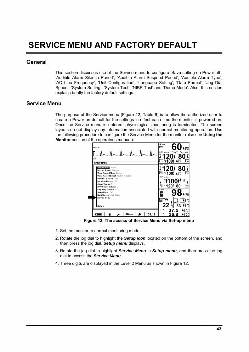
43
SERVICE MENU AND FACTORY DEFAULT General
This section discusses use of the Service menu to configure ‘Save setting on Power off’, ‘Audible Alarm Silence Period’, ‘Audible Alarm Suspend Period’, ‘Audible Alarm Type’, ‘AC Line Frequency’, ‘Unit Configuration’, ‘Language Setting’, ‘Date Format’, ‘Jog Dial Speed’, ‘System Setting’, ‘System Test’, ‘NIBP Test’ and ‘Demo Mode'. Also, this section explains briefly the factory default settings.
Service Menu
The purpose of the Service menu (Figure 12, Table 9) is to allow the authorized user to create a Power-on default for the settings in effect each time the monitor is powered on. Once the Service menu is entered, physiological monitoring is terminated. The screen layouts do not display any information associated with normal monitoring operation. Use the following procedure to configure the Service Menu for the monitor (also see Using the Monitor section of the operator’s manual):
Figure 12. The access of Service Menu via Set-up menu
1. Set the monitor to normal monitoring mode.
2. Rotate the jog dial to highlight the Setup icon located on the bottom of the screen, and then press the jog dial. Setup menu displays.
3. Rotate the jog dial to highlight Service Menu in Setup menu, and then press the jog dial to access the Service Menu.
4. Three digits are displayed in the Level 2 Menu as shown in Figure 12.

44
Figure 13. Entering the pass code
Note: The access code is 6, 0, 6. It is set at the factory and may not be changed. 5. Rotate the jog dial to highlight the top of the digits. Press the jog dial to enter Pass
code.
6. Rotate the jog dial until “6” appears, then press the jog dial.
7. Repeat step 5-6 to enter all the access code “6”“0 “6”.
Figure 14. Service Menu
8. The Service Menu will now be present. The available Service Menu items are explained
in Figure 6 and Table 9. Make changes to these menu items as desired by rotating and pressing the jog dial.
9. Select “Done”. The monitor will present the message “All changes made to the power-up defaults will be in effect the next time the monitor is turned on:” before turned off.
10. Turn off the monitor, and then turn on the monitor again. Note: The monitor must be powered off upon selecting “Done” to save any changes into
the monitor, and then the changes made to the Power on defaults will be in effect next time the monitor is powered up.

45
Table 9. Service menu Level 1 Menu Level 2 Menu Level 3 Menu
Save settings on Power off Custom Back Up Default Audible Alarm Silence Period 30, 60 90, 120 seconds Audible Alarm Suspend Period Off, 10, 20, 30, 60 minutes, Indefinite Audible Alarm Type IEC60601-1-8 AC Line Frequency 50Hz, 60Hz Unit Configuration NIBP mmHg, kPa IBP mmHg, kPa CO2 mmHg, %, kPa Temperature °C, °F Language Setting 한국어 (Korean), 中文 (Chinese), Dansk (Danish),
Nederlands (Dutch), English, Français (French), Deutsch (German), Italiano (Italian), 日本語 (Japanese), Português (Portuguese), Español (Spanish), Svenska (Swedish)
Date Format Year/Month/Day, Month/Day/Year, Day/Month/Year Jog Dial Speed Fast, Normal LAN Setting For future release System Setting Monitor On Time Recorder On Time Battery Deep Discharges System Software Version Module Version Print value of configuration Tone Set (Detail) System Test Switch/LED Test LCD Test Alarm Audible Test Tone Audible Test Recorder Test Backup RAM Clear NIBP Test Pressure Sensor Accuracy Test Air Leakage Test Inflation Speed Test Initial Deflation Test (I) Initial Deflation Test (II) Deflations Speed Test Offset Test Demo Mode On, Off Done The monitor will be powered off upon selecting
“Done”, then any changes will be in effect next time the unit is powered up.
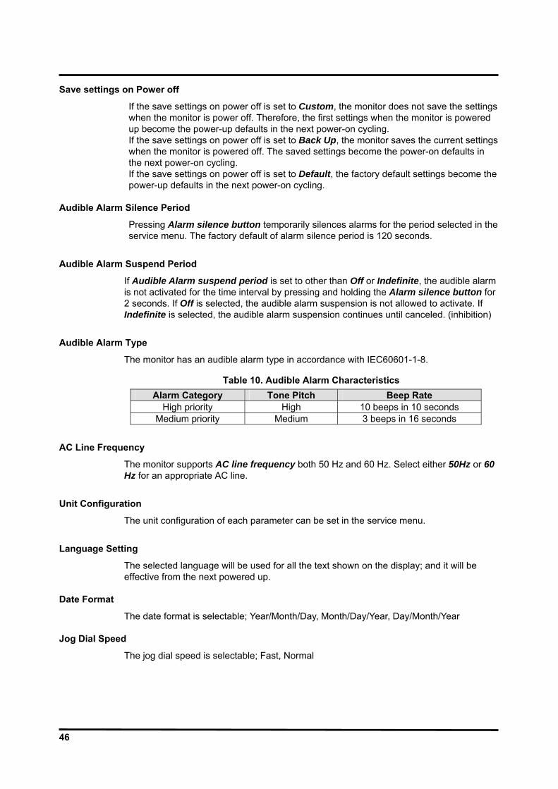
46
Save settings on Power off
If the save settings on power off is set to Custom, the monitor does not save the settings when the monitor is power off. Therefore, the first settings when the monitor is powered up become the power-up defaults in the next power-on cycling. If the save settings on power off is set to Back Up, the monitor saves the current settings when the monitor is powered off. The saved settings become the power-on defaults in the next power-on cycling. If the save settings on power off is set to Default, the factory default settings become the power-up defaults in the next power-on cycling.
Audible Alarm Silence Period
Pressing Alarm silence button temporarily silences alarms for the period selected in the service menu. The factory default of alarm silence period is 120 seconds.
Audible Alarm Suspend Period
If Audible Alarm suspend period is set to other than Off or Indefinite, the audible alarm is not activated for the time interval by pressing and holding the Alarm silence button for 2 seconds. If Off is selected, the audible alarm suspension is not allowed to activate. If Indefinite is selected, the audible alarm suspension continues until canceled. (inhibition)
Audible Alarm Type
The monitor has an audible alarm type in accordance with IEC60601-1-8.
Table 10. Audible Alarm Characteristics Alarm Category Tone Pitch Beep Rate
High priority High 10 beeps in 10 seconds Medium priority Medium 3 beeps in 16 seconds
AC Line Frequency
The monitor supports AC line frequency both 50 Hz and 60 Hz. Select either 50Hz or 60 Hz for an appropriate AC line.
Unit Configuration
The unit configuration of each parameter can be set in the service menu.
Language Setting
The selected language will be used for all the text shown on the display; and it will be effective from the next powered up.
Date Format
The date format is selectable; Year/Month/Day, Month/Day/Year, Day/Month/Year Jog Dial Speed
The jog dial speed is selectable; Fast, Normal

47
System Setting
This menu displays the information for system settings. Monitor On Time This menu displays the number of hours, minutes and seconds, rounded to the nearest hour that the monitor has been operational. The term that the monitor is in the service mode is not included.
Recorder On Time This menu displays the number of hours, minutes and seconds, rounded to the nearest hour that the Recorder has been operational. Battery Deep Discharges This menu displays the number of deep-discharge cycles seen by the battery. The monitor records a deep discharge cycle when the monitor is automatically turned off after a “Critically Low Battery” alarm is issued. System Software Version This menu displays the revision level of the system software. The revision level is also shown on the LCD as part of the Copyright screen. Module Version This menu displays information for each module or board version. Print Value of Configuration This menu is used to print out the set values. This function is useful when collecting a wrong value. Tone Set (Detail) This menu used to set the HR/PR tone with High, Medium, Low or SpO2.
Note: The values of Monitor On Time, Recorder On Time and Battery Deep Discharges
may not be reset, but they will be reset to zero when a new CPU module is installed.
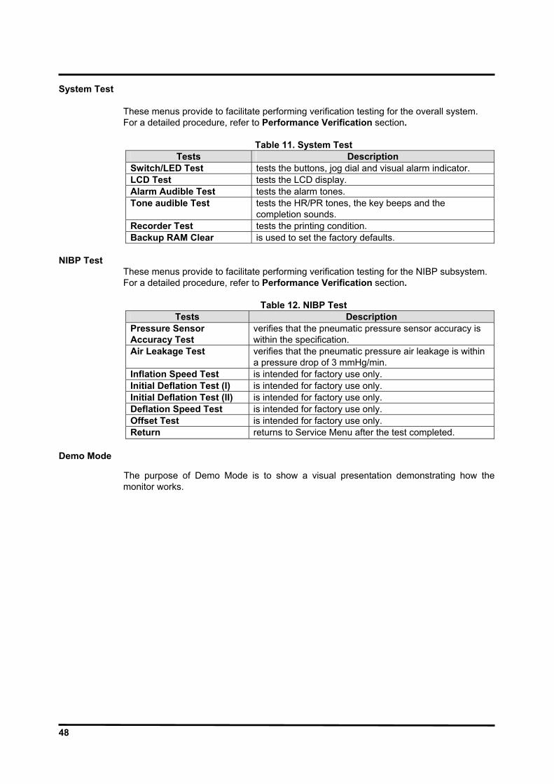
48
System Test
These menus provide to facilitate performing verification testing for the overall system. For a detailed procedure, refer to Performance Verification section.
Table 11. System Test
Tests Description Switch/LED Test tests the buttons, jog dial and visual alarm indicator. LCD Test tests the LCD display. Alarm Audible Test tests the alarm tones. Tone audible Test tests the HR/PR tones, the key beeps and the
completion sounds. Recorder Test tests the printing condition. Backup RAM Clear is used to set the factory defaults.
NIBP Test
These menus provide to facilitate performing verification testing for the NIBP subsystem. For a detailed procedure, refer to Performance Verification section.
Table 12. NIBP Test Tests Description
Pressure Sensor Accuracy Test
verifies that the pneumatic pressure sensor accuracy is within the specification.
Air Leakage Test verifies that the pneumatic pressure air leakage is within a pressure drop of 3 mmHg/min.
Inflation Speed Test is intended for factory use only. Initial Deflation Test (I) is intended for factory use only. Initial Deflation Test (II) is intended for factory use only. Deflation Speed Test is intended for factory use only. Offset Test is intended for factory use only. Return returns to Service Menu after the test completed.
Demo Mode
The purpose of Demo Mode is to show a visual presentation demonstrating how the monitor works.

49
Factory Default Settings
Factory default settings are divided into adult and neonatal as described in Table 13. The patient mode is preset to “Adult” mode. Alarm limits will be automatically changed to the default settings for each patient mode as the mode is changed to Adult or Neonatal mode.
Table 13. Factory Default Settings
Factory Defaults Parameter Ranges/Selections Adult NeonatalECG ECG Cable Select 3 Leads, 5 Leads, AUTO AUTO AUTO ECG Lead Select I, II, III, aVR, aVL, aVF, V(Chest Lead) - - ECG Size (mm/mV) ×1/4, ×1/2, ×1, ×1.5, ×2 ×1 ×1 ECG Filter Mode Monitor, Low Extend, Filter,
Respiration Rejection Monitor Monitor
ECG Pacer Detect On, Off Off Off ECG Sweep Speed 12.5, 25.0, 50.0 mm/s 25.0 mm/s 25.0 mm/sHR/PR Source AUTO, HR, PR AUTO AUTO HR/PR Upper Alarm Limits 35 to 305 bpm (Adult/Neo) (5 bpm steps) 180 bpm 200 bpm HR/PR Lower Alarm Limits 30 to 300 bpm (Adult/Neo) (5 bpm steps) 40 bpm 50 bpm NIBP NIBP Initial Cuff Inflation 120, 140, 160, 180, 200, 220mmHg (Adult)
(16.0, 18.7, 21.3, 24.0, 26.7, 29.3, kPa) 80, 100, 120, 140 mmHg (Neo) (9.3, 12.0, 14.7, 16.0, 18.7 kPa)
180 mmHg 24.0 kPa
120 mmHg16.0 kPa
BP On Alarm On, Off Off Off Smart Clock On, Off On On Smart Inflation On, Off On On Completion Sound On, Off On On NIBP Automatic Mode Interval Off, Cont, 1, 2, 2.5, 3, 5, 10, 15, 20, 30, 45, 60,
90,120 ,180 minutes Off Off
NIBP SYS Upper Alarm Limits 60 to 260 mmHg (Adult), 40 to 130 mmHg (Neo) 8.0 to 34.7 kPa (Adult), 5.3 to 17.3 kPa (Neo) (10 mmHg / 1.3 kPa steps)
200 mmHg 26.7 kPa
130 mmHg17.3 kPa
NIBP SYS Lower Alarm Limits 50 to 250 mmHg (Adult), 30 to 120 mmHg (Neo) 6.7 to 33.3 kPa (Adult), 4.0to 16.0 kPa (Neo) (10 mmHg / 1.3 kPa steps)
70 mmHg 9.3 kPa
50 mmHg6.7 kPa
NIBP DIA Upper Alarm Limits 40 to 210 mmHg (Adult), 20 to 100 mmHg (Neo) 5.3 to 28.0 kPa (Adult), 2.7 to 13.3 kPa (Adult) (10 mmHg / 1.3 kPa steps)
160 mmHg 21.3 kPa
100 mmHg13.3 kPa
NIBP DIA Lower Alarm Limits 30 to 200 mmHg (Adult), 10 to 90 mmHg (Neo) 4.0 to 26.7 kPa (Adult), 1.3 to 12.0 kPa (Neo) (10 mmHg / 1.3 kPa steps)
30 mmHg 4.0 kPa
10 mmHg1.3 kPa
NIBP MAP Upper Alarm Limits 50 to 240 mmHg (Adult), 30 to 110 mmHg (Neo) 6.7 to 32.0 kPa (Adult), 4.0 to 14.7 kPa (Neo) (10 mmHg / 1.3 kPa steps)
180 mmHg 24.0 kPa
110 mmHg14.6 kPa
NIBP MAP Lower Alarm Limits 40 to 230 mmHg (Adult), 20 to 100 mmHg (Neo) 5.3 to 30.7 kPa (Adult), 2.7 to 13.3 kPa (Neo) (10 mmHg / 1.3 kPa steps)
40 mmHg 5.3 kPa
20 mmHg2.7 kPa
IBP IBP Sweep Speed 12.5, 25.0, 50.0 mm/s 25.0 mm/s 25.0 mm/sPressure Zero Setting Yes, No No No P1 Label P1, ABP ABP ABP
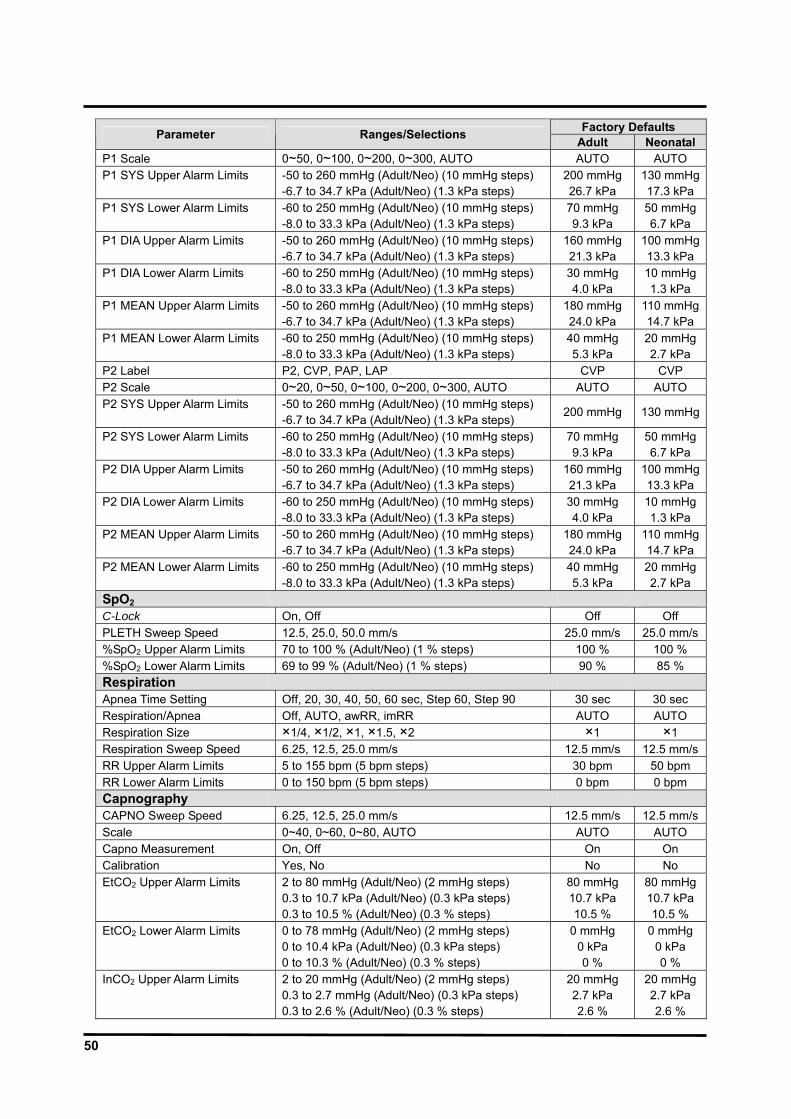
50
Factory Defaults Parameter Ranges/Selections Adult NeonatalP1 Scale 0~50, 0~100, 0~200, 0~300, AUTO AUTO AUTO P1 SYS Upper Alarm Limits -50 to 260 mmHg (Adult/Neo) (10 mmHg steps)
-6.7 to 34.7 kPa (Adult/Neo) (1.3 kPa steps) 200 mmHg 26.7 kPa
130 mmHg17.3 kPa
P1 SYS Lower Alarm Limits -60 to 250 mmHg (Adult/Neo) (10 mmHg steps) -8.0 to 33.3 kPa (Adult/Neo) (1.3 kPa steps)
70 mmHg 9.3 kPa
50 mmHg6.7 kPa
P1 DIA Upper Alarm Limits -50 to 260 mmHg (Adult/Neo) (10 mmHg steps) -6.7 to 34.7 kPa (Adult/Neo) (1.3 kPa steps)
160 mmHg 21.3 kPa
100 mmHg13.3 kPa
P1 DIA Lower Alarm Limits -60 to 250 mmHg (Adult/Neo) (10 mmHg steps) -8.0 to 33.3 kPa (Adult/Neo) (1.3 kPa steps)
30 mmHg 4.0 kPa
10 mmHg1.3 kPa
P1 MEAN Upper Alarm Limits -50 to 260 mmHg (Adult/Neo) (10 mmHg steps) -6.7 to 34.7 kPa (Adult/Neo) (1.3 kPa steps)
180 mmHg 24.0 kPa
110 mmHg14.7 kPa
P1 MEAN Lower Alarm Limits -60 to 250 mmHg (Adult/Neo) (10 mmHg steps) -8.0 to 33.3 kPa (Adult/Neo) (1.3 kPa steps)
40 mmHg 5.3 kPa
20 mmHg2.7 kPa
P2 Label P2, CVP, PAP, LAP CVP CVP P2 Scale 0~20, 0~50, 0~100, 0~200, 0~300, AUTO AUTO AUTO P2 SYS Upper Alarm Limits -50 to 260 mmHg (Adult/Neo) (10 mmHg steps)
-6.7 to 34.7 kPa (Adult/Neo) (1.3 kPa steps) 200 mmHg 130 mmHg
P2 SYS Lower Alarm Limits -60 to 250 mmHg (Adult/Neo) (10 mmHg steps) -8.0 to 33.3 kPa (Adult/Neo) (1.3 kPa steps)
70 mmHg 9.3 kPa
50 mmHg6.7 kPa
P2 DIA Upper Alarm Limits -50 to 260 mmHg (Adult/Neo) (10 mmHg steps) -6.7 to 34.7 kPa (Adult/Neo) (1.3 kPa steps)
160 mmHg 21.3 kPa
100 mmHg13.3 kPa
P2 DIA Lower Alarm Limits -60 to 250 mmHg (Adult/Neo) (10 mmHg steps) -8.0 to 33.3 kPa (Adult/Neo) (1.3 kPa steps)
30 mmHg 4.0 kPa
10 mmHg1.3 kPa
P2 MEAN Upper Alarm Limits -50 to 260 mmHg (Adult/Neo) (10 mmHg steps) -6.7 to 34.7 kPa (Adult/Neo) (1.3 kPa steps)
180 mmHg 24.0 kPa
110 mmHg14.7 kPa
P2 MEAN Lower Alarm Limits -60 to 250 mmHg (Adult/Neo) (10 mmHg steps) -8.0 to 33.3 kPa (Adult/Neo) (1.3 kPa steps)
40 mmHg 5.3 kPa
20 mmHg2.7 kPa
SpO2 C-Lock On, Off Off Off PLETH Sweep Speed 12.5, 25.0, 50.0 mm/s 25.0 mm/s 25.0 mm/s%SpO2 Upper Alarm Limits 70 to 100 % (Adult/Neo) (1 % steps) 100 % 100 % %SpO2 Lower Alarm Limits 69 to 99 % (Adult/Neo) (1 % steps) 90 % 85 % Respiration Apnea Time Setting Off, 20, 30, 40, 50, 60 sec, Step 60, Step 90 30 sec 30 sec Respiration/Apnea Off, AUTO, awRR, imRR AUTO AUTO Respiration Size ×1/4, ×1/2, ×1, ×1.5, ×2 ×1 ×1 Respiration Sweep Speed 6.25, 12.5, 25.0 mm/s 12.5 mm/s 12.5 mm/sRR Upper Alarm Limits 5 to 155 bpm (5 bpm steps) 30 bpm 50 bpm RR Lower Alarm Limits 0 to 150 bpm (5 bpm steps) 0 bpm 0 bpm Capnography CAPNO Sweep Speed 6.25, 12.5, 25.0 mm/s 12.5 mm/s 12.5 mm/sScale 0~40, 0~60, 0~80, AUTO AUTO AUTO Capno Measurement On, Off On On Calibration Yes, No No No EtCO2 Upper Alarm Limits 2 to 80 mmHg (Adult/Neo) (2 mmHg steps)
0.3 to 10.7 kPa (Adult/Neo) (0.3 kPa steps) 0.3 to 10.5 % (Adult/Neo) (0.3 % steps)
80 mmHg 10.7 kPa 10.5 %
80 mmHg10.7 kPa10.5 %
EtCO2 Lower Alarm Limits 0 to 78 mmHg (Adult/Neo) (2 mmHg steps) 0 to 10.4 kPa (Adult/Neo) (0.3 kPa steps) 0 to 10.3 % (Adult/Neo) (0.3 % steps)
0 mmHg 0 kPa 0 %
0 mmHg 0 kPa 0 %
InCO2 Upper Alarm Limits 2 to 20 mmHg (Adult/Neo) (2 mmHg steps) 0.3 to 2.7 mmHg (Adult/Neo) (0.3 kPa steps) 0.3 to 2.6 % (Adult/Neo) (0.3 % steps)
20 mmHg 2.7 kPa 2.6 %
20 mmHg2.7 kPa 2.6 %

51
Factory Defaults Parameter Ranges/Selections Adult NeonatalInCO2 Lower Alarm Limits 0 to 18 mmHg (Adult/Neo) (2 mmHg steps)
0 to 2.4 kPa (Adult/Neo) (0.3 kPa steps) 0 to 2.3 % (Adult/Neo) (0.3 % steps)
0 mmHg 0 kPa 0 %
0 mmHg 0 kPa 0 %
Temperature T1, T2 Upper Alarm Limits 15.0 to 45.5 °C (Adult/Neo) (0.5º C steps)
59.0 to 113.9 °F (Adult/Neo) (0.1°F steps) 38.0 °C
(100.4 º F) 39.0 °C
(102.2 º F)T1, T2 Lower Alarm Limits 14.5 to 45.0 °C (Adult/Neo) (0.5º C steps)
58.1 to 113.0 °F (Adult/Neo) (0.1°F steps) 14.5 °F
(58.1 °F) 14.5 °F
(58.1 °F) Others Patient Mode Adult, Neonatal Adult Record Speed** 25.0 mm/s, 50.0 mm/s 25.0 mm/s Wave Record Time** 20 sec, Continuous (10sec delay) 20 sec
Wave Record Select** ECG1 + ECG2, PLETH, RESP, IBP1, IBP2 or CAPNO ECG1 + PLETH
Record on Alarm** On, Off Off Auto List Record** On, Off Off Alarm Volume 1, 2, 3, 4, 5, 6, 7, 8 5 HR/PR tone Volume Off, 1, 2, 3, 4, 5, 6, 7 4 Key Beep Volume Off, 1, 2, 3, 4, 5, 6, 7 4 Sleep Mode Off, 10, 20, 30 min Off Main Screen 4ch-wave, 6ch-wave, Big Number - Alarm Limits Display On, Off On Auto Alarm On, Off Off Auto Alarm Setting (Upper) +10 to +50% +40% Auto Alarm Setting (Lower) -50 to -10% -20% Save Time Interval Off, 0.5,1,2,2.5,5,10,15,20,30,60,120 min Off Graphical Display On/Off On/Off for each parameter On Save Setting on Power Off* Custom, Back up, Default Back up Audible Alarm Silence Period* 30, 60, 90, 120 sec 120 sec Audible Alarm Suspend Period*
Off, 10, 20, 30, 60 min, Indefinite (Alarm Inhibition) Indefinite
AC Line Frequency* 50, 60 Hz 60 Hz NIBP Unit* mmHg, kPa mmHg IBP Unit* mmHg, kPa mmHg CO2 Unit*` mmHg, %, kPa mmHg Temperature Unit* °C , °F °C HR/PR Tone Set* High, Med, Low, SpO2 High Date Format* year/month/day, month/day/year, day/month/year year/month/day Jog Dial Speed* Fast, Normal Normal Demo Mode* On, Off Off
Language*
한국어 (Korean), 中文 (Chinese), Dansk (Danish), Nederlands (Dutch), English, Français (French), Deutsch (German), Italiano (Italian), 日本語 (Japanese), Português (Portuguese), Español (Spanish), Svenska (Swedish)
English
Note: An asterisk (*) by a parameter in the above table indicates that the parameter can only be changed by authorized personnel as described in the service manual Note: Asterisks (**) by a parameter in the above table indicate the settings only when an optional recorder is installed in the monitor.

52
This page is intentionally left blank.

53
FIRMWARE DOWNLOAD General
This section is for the purpose for reloading Firmware into the monitor when the possibility of corrupted Firmware exists, or updating Firmware with a new system revision (system/device version). Call your local supplier for the latest version of Firmware utility required.
Equipment Needed
Table 14 lists the equipment required for Firmware download.
Table 14. Required Equipments for Firmware Download Equipment Description Firmware Download Tool USB Memory with BP-S510 Field Utility
(firmware downloading software) How to Download
1. Turn off the monitor.
2. Turn on the monitor by pressing the Power on/off button.
3. The monitor displays the bar while the checksum for the flash memory is in progress
4. Press NIBP start/stop button and NIBP interval simultaneously before filled the bar completely.
5. The monitor will display the firmware upgrade screen as shown below figure 15.
Figure 15. Firmware downloading display
6. Connect USB memory to the USB port on the right panel of the monitor.
7. BP-S510 Field Utility will be run automatically. It will take about 5 minutes.

54
8. Three bars on the screen indicate the progress status for the downloading.
“T” displays the transferring status from the USB memory to the monitor.
“D” displays the deleting status of the flash memory.
“W” displays the writing status of the flash memory.
9. When three bars are filled, the completion code will be displayed in the box located on the center of the screen as shown Figure 16. Refer to Table 15.
Figure 16. Firmware downloading completion
Table 15. Completion codes
Code Description I.00.0001 USB is not connected S.00.0001 Find USB S.01.0001 Boot download & fusing complete S.02.0001 Main download & fusing complete
Note: If any problem during Firmware downloading, the error code will be displayed in the box located on the center of the screen. Refer to Firmware Download in Troubleshooting section.
10. After completion of downloading, turn off the monitor.
11. Disconnect the USB memory from the monitor.
12. After a few seconds, turn on the monitor again.
13. Check the system version indicated on the copyright screen.
Note: You can check the boot version on the bar while the monitor performs the checksum for the memory.
14. Perform the tests specified in Performance Verification section.
Note: When a new firmware downloading is completed, the monitor still keeps the
previous settings. Note: If any problem occurs during Firmware downloading, refer to Firmware Download in
Troubleshooting section.
55
TROULBESHOOTING General
This section provides information that can be helpful in troubleshooting the BP-S510 monitor.
How to Use This Section
If the Unit is not functioning property, please check on the following item, before calling for repair service. Use this section in conjunction with Performance Verification section and Spare Parts section. To remove and replace a part suspected the trouble, follow the instructions in Disassembly Guide section.
Who Should Perform Repairs
Only qualified service personnel should open the monitor housing, remove and replace components, or make adjustments in accordance with this service manual. If your medical facility does not have qualified service personnel, contact your local supplier.
Replacement Level Supported
The replacement level supported for this product is to the printed circuit board (PCB assembly) and major subassembly level. Once you isolate a suspected PCB assembly, follow the procedures in Disassembly Guide section, to replace the PCB assembly with a known good PCB assembly. Check to see if the trouble symptom disappears and that the monitor passes all performance tests. If the trouble symptom persists, swap back the replacement PCB assembly with the suspected malfunctioning PCB assembly (the original PCB assembly that was installed when you started troubleshooting) and continue troubleshooting as directed in this section. Obtaining Replacement Parts Omron Healthcare provides technical assistance information and replacement parts. To obtain replacement parts, contact your local supplier. Refer to the part names and part numbers listed in Spare Parts section.

56
Troubleshooting Guide Problems with the monitor are separated into the categories for further troubleshooting instructions. Note: Taking the recommended actions discussed in this section will correct the majority
of problems you will encounter. However, problems not covered here can be resolved by calling your local supplier.
Table 16. Problem Categories
Categories Symptoms 1. Power 1.1: AC Power is on but Battery indicator is not lighting.
1.2: Monitor does not power up though the button is pressed. 1.3: Monitor shuts off automatically after power on. 1.4: Monitor does not power on with battery. 1.5: Monitor makes buzzer sound when turning on the monitor.
2. Display 2.1: The LCD display is blacked up after completed the POST. 2.2: LCD is illuminated but no data is visible. 2.3: Some pixels are not lighting.
3. Sound 3.1: Audible alarm not sound. 3.2: The key press tone fails to sound.
4. Jog dial and Buttons
4.1: One or some buttons does not respond. 4.2: The Jog Dial rotates, but no responds from the LCD display.
5. NIBP 5.1: The cuff does not inflate. 5.2: Error Message C11 or E03. 5.3: The NIBP value is not reliable.
6. SpO2 6.1: The SpO2 sensor does not light. 6.2: Sensor is lighting but no display on SpO2 window.
7. CO2 7.1: CO2 module does not operate. 7.2: CO2 module fails to calibration.
8. Temperature 8.1: TEMP {1 or 2} : Internal Error is displayed. 9. Respiration 9.1: Respiration (imRR) gets too much noise or cannot measure
the Respiration (imRR). 9.2: Respiration is not displayed. 9.3: Does not measure Respiration (awRR).
10. Firmware download
Error Code displayed.
11. Technical alarm condition
Alarm message or error code displayed.

57
1. Power Power problems are related to AC and/or Battery as follows. If the action requires replacement of the components, refer to Disassembly Guide section. CAUTION: Electrical shock hazard. Disconnect a power cord from the monitor before attempting to open or disassemble the monitor.
Symptom 1.1: AC Power is on but Battery charging indicator is not lighting. Cause Check Action RemarkPower cord is not connected to the AC
AC power cord is properly connected to the AC outlet.
Re-connect AC connection or replace the AC power cord.
Battery is not installed. Battery is installed. Install the battery.
SMPS is malfunctioning Charging voltage. Replace the SMPS
Front key board is malfunctioning.
Front key board or Front key wire.
Replace the front key board or the front key wire.
Symptom 1.2: Monitor does not power up though the button is pressed. Cause Check Action RemarkSMPS is malfunctioning Charging voltage. Replace the SMPS
Fuse of SMPS is burnt out.
Check the fuse of SMPS.
Replace the fuse or SMPS.
Hub board is malfunctioning.
Connection between SMPS and Main Board.
Replace the hub board.
Front key board is malfunctioning.
Front key board or Front key wire.
Replace the front key board or front key wire.
Main board is malfunctioning.
- Replace the main Board.
Symptom 1.3: Monitor shuts off automatically after power on. Cause Check Action RemarkMain board is malfunctioning.
- Replace the main board.
Symptom 1.4: Monitor does not power on with battery.
Cause Check Action RemarkBattery is not installed. Battery is installed. Pull out and re-install
the battery.
Battery is totally discharged.
Battery voltage. Recharge the battery for 12 hours. Replace the battery.
SMPS does not recharge the battery
Charging voltage of the SMPS
Replace the SMPS.
Hub board is malfunctioning
Connection between the SMPS and the main Board.
Replace the hub board.
Main board is malfunctioning.
- Replace the main Board.

58
Symptom 1.5: Monitor makes buzzer sound when turning on the monitor.
2. Display
Symptom 2.1: The LCD display is blacked up after normal POST.
2.2: LCD is illuminated but no data is visible.
2.3: Some pixels are not lighting. Cause Check Action RemarkLCD cable is loose. LCD cable connection
between Front assembly and Main board.
Reconnect the cable or replace the cable.
Inverter wire is loose. Inverter wire connection between Front assembly and Main board.
Reconnect the cable or replace the cable.
LCD is malfunctioning - Replace the LCD.
Symptom 2.4: Display values are missing or erratic. Cause Check Action RemarkMeasurement Cables are not properly connected.
Each parameter cable connection. Zeroing the IBP Warming up the CO2 module CO2 calibration.
Replace the each cable. Replace the relevant parameter cables. Replace the relevant board or modules. Replace the Main board.
3. Sound
Symptom 3.1: Audible alarm not sound. Cause Check Action RemarkAlarm silence is activated.
Alarm Silence button Cancel the alarm silence condition.
Speaker is faulty or wire is loose.
Speaker wire connection between speaker and Side Key Board.
Reconnect the wire or replace the speaker
16pin cable between Side Key Board and Main board is loose.
Check the cable connection.
Replace the cable or replace the 16 pin cable.
Main board is malfunctioning.
- Replace the main board.
Cause Check Action RemarkHub board, Main board, SMPS or NIBP module are not assembled properly
Assemble between the boards
Reassemble the boards Replace the hub board. Replace the NIBP module. Replace the main board. Replace the SMPS.

59
Symptom 3.2: The key press tone fails to sound. Cause Check Action RemarkBeep volume is set to zero.
Key beep volume in Setup menu.
Increase the key beep volume in Setup menu.
Speaker is faulty or wire is loose.
Speaker wire connection between speaker and Side Key Board.
Reconnect the wire or replace the speaker
16 pin cable between Side key board and Main board is loose.
Check the cable connection.
Replace the cable or replace the 16 pin cable.
Main board is malfunctioning.
- Replace the main board.
4. Jog Dial and Button problems
Symptom 4.1: One or some buttons does not respond. Cause Check Action RemarkSide key board or Front Key board is malfunctioning.
- Replace the relevant board.
Front key wire is loose. Cable connection. Reconnect the cable or replace the cables.
Main board is malfunctioning.
- Replace the main Board.
Symptom 4.2: The Jog Dial rotates, but no responds from the LCD display. Cause Check Action RemarkThe 16 pin cable is loose.
Cable connection between the boards.
Reconnect the cable or replace it.
Side key board is malfunctioning.
- Replace the side key Board.
Main board is malfunctioning.
- Replace the main Board.
5. NIBP
Symptom 5.1: The cuff does not inflate. Cause Check Action Remark Cuff or Cuff hose is folded.
Cuff and hose connection.
Unfold the cuff or cuff hose.
NIBP tube inside of the monitor is blocked or kinked.
NIBP tube of the monitor inside.
Unfold the NIBP tube.
NIBP module is malfunctioning.
- Replace the NIBP module.
Main board is malfunctioning.
- Replace the main board.

60
Symptom 5.2: Error Message C11 or E03 Cause Check Action Remark NIBP tube is disconnected.
The connection of NIBP tube.
Re-connect the NIBP tube. If the problem persists, replace the NIBP module.
Symptom 5.3: The NIBP value is not reliable. Cause Check Action Remark NIBP module is malfunctioning.
Sensor accuracy test, Air leakage test and Over-pressure test
Replace the NIBP module.
6. SpO2
Symptom 6.1: The SpO2 sensor does not light. Cause Check Action Remark The connection between SpO2 sensor and extension cable is loose.
Connection between sensor and extension cable.
Reconnect them.
SpO2 module does not work.
- Replace the SpO2 module.
Main board is malfunctioning.
- Replace the Main Board.
Symptom 6.2: Sensor is lighting but no display on SpO2 window. Cause Check Action Remark SpO2 module does not work.
- Replace the SpO2 module.
Main board is malfunctioning.
- Replace the main board.

61
7. CO2
Symptom 7.1: CO2 module does not operate.
7.2: CO2 module fails to calibration. Cause Check Action Remark Measurement cables were not properly connected.
Cable connection of each point.
Re-set up the cable connections or replace the CO2 accessories.
CO2 module does not operate.
- Replace the CO2 module.
Main board is malfunctioning.
- Replace the main board.
8. Temperature
Symptom 8.1: TEMP {1 or 2} : Internal Error is displayed. Cause Check Action Remark Temperature reset does not work.
- Replace the main board.
9. Respiration Symptom 9.1: Respiration (imRR) gets too much noise or cannot measure the
Respiration. 9.2: Respiration is not displayed.
Cause Check Action Remark ECG accessories are improperly connected or electrode is contaminated.
Accessory connection and electrode.
Replace the accessories or electrode.
ECG board is malfunctioning.
- Replace the ECG board.
Main board is malfunctioning.
- Replace the main board.
Symptom 9.3 : Monitor does not measure Respiration (awRR). Cause Check Action Remark CO2 module is malfunctioning.
- Replace the CO2 module.
Main board is malfunctioning.
- Replace the main board.
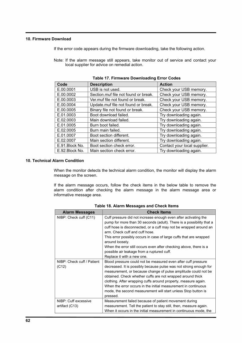
62
10. Firmware Download
If the error code appears during the firmware downloading, take the following action.
Note: If the alarm message still appears, take monitor out of service and contact your local supplier for advice on remedial action.
Table 17. Firmware Downloading Error Codes
Code Description Action E.00.0001 USB is not used. Check your USB memory. E.00.0002 Section.muf file not found or break. Check your USB memory. E.00.0003 Ver.muf file not found or break. Check your USB memory. E.00.0004 Update.muf file not found or break. Check your USB memory. E.00.0005 Binary file not found or break. Check your USB memory. E.01.0003 Boot download failed. Try downloading again. E.02.0003 Main download failed. Try downloading again. E.01.0005 Burn boot failed. Try downloading again. E.02.0005 Burn main failed. Try downloading again. E.01.0007 Boot section different. Try downloading again. E.02.0007 Main section different. Try downloading again. E.91.Block No. Boot section check error. Contact your local supplier. E.92.Block No. Main section check error. Try downloading again.
10. Technical Alarm Condition
When the monitor detects the technical alarm condition, the monitor will display the alarm message on the screen. If the alarm message occurs, follow the check items in the below table to remove the alarm condition after checking the alarm message in the alarm message area or informative message area.
Table 18. Alarm Messages and Check Items
Alarm Messages Check Items NIBP: Check cuff (C11) Cuff pressure did not increase enough even after activating the
pump for more than 30 seconds (adult). There is a possibility that a cuff hose is disconnected, or a cuff may not be wrapped around an arm. Check cuff and cuff hose. This error possibly occurs in case of large cuffs that are wrapped around loosely. When the error still occurs even after checking above, there is a possible air leakage from a ruptured cuff. Replace it with a new one.
NIBP: Check cuff / Patient (C12)
Blood pressure could not be measured even after cuff pressure decreased. It is possibly because pulse was not strong enough for measurement, or because change of pulse amplitude could not be obtained. Check whether cuffs are not wrapped around thick clothing. After wrapping cuffs around property, measure again. When the error occurs in the initial measurement in continuous mode, the second measurement will start unless Stop button is pressed.
NIBP: Cuff excessive artifact (C13)
Measurement failed because of patient movement during measurement. Tell the patient to stay still, then, measure again. When it occurs in the initial measurement in continuous mode, the
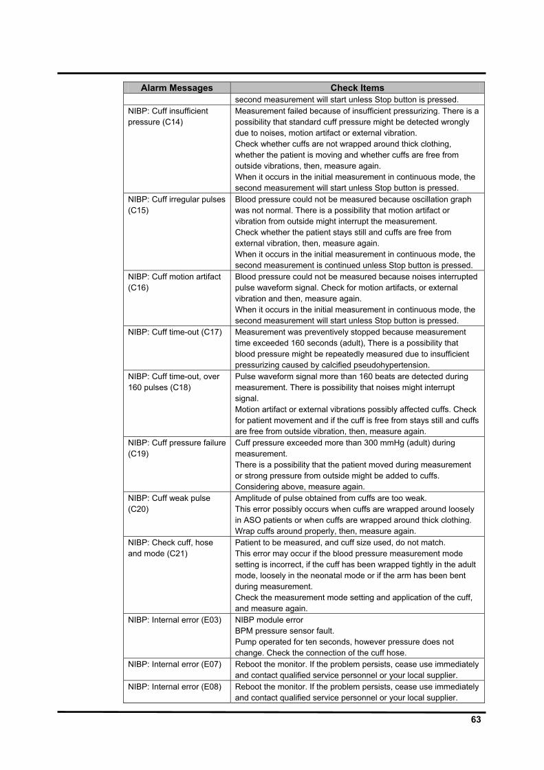
63
Alarm Messages Check Items second measurement will start unless Stop button is pressed.
NIBP: Cuff insufficient pressure (C14)
Measurement failed because of insufficient pressurizing. There is a possibility that standard cuff pressure might be detected wrongly due to noises, motion artifact or external vibration. Check whether cuffs are not wrapped around thick clothing, whether the patient is moving and whether cuffs are free from outside vibrations, then, measure again. When it occurs in the initial measurement in continuous mode, the second measurement will start unless Stop button is pressed.
NIBP: Cuff irregular pulses (C15)
Blood pressure could not be measured because oscillation graph was not normal. There is a possibility that motion artifact or vibration from outside might interrupt the measurement. Check whether the patient stays still and cuffs are free from external vibration, then, measure again. When it occurs in the initial measurement in continuous mode, the second measurement is continued unless Stop button is pressed.
NIBP: Cuff motion artifact (C16)
Blood pressure could not be measured because noises interrupted pulse waveform signal. Check for motion artifacts, or external vibration and then, measure again. When it occurs in the initial measurement in continuous mode, the second measurement will start unless Stop button is pressed.
NIBP: Cuff time-out (C17) Measurement was preventively stopped because measurement time exceeded 160 seconds (adult), There is a possibility that blood pressure might be repeatedly measured due to insufficient pressurizing caused by calcified pseudohypertension.
NIBP: Cuff time-out, over 160 pulses (C18)
Pulse waveform signal more than 160 beats are detected during measurement. There is possibility that noises might interrupt signal. Motion artifact or external vibrations possibly affected cuffs. Check for patient movement and if the cuff is free from stays still and cuffs are free from outside vibration, then, measure again.
NIBP: Cuff pressure failure (C19)
Cuff pressure exceeded more than 300 mmHg (adult) during measurement. There is a possibility that the patient moved during measurement or strong pressure from outside might be added to cuffs. Considering above, measure again.
NIBP: Cuff weak pulse (C20)
Amplitude of pulse obtained from cuffs are too weak. This error possibly occurs when cuffs are wrapped around loosely in ASO patients or when cuffs are wrapped around thick clothing. Wrap cuffs around properly, then, measure again.
NIBP: Check cuff, hose and mode (C21)
Patient to be measured, and cuff size used, do not match. This error may occur if the blood pressure measurement mode setting is incorrect, if the cuff has been wrapped tightly in the adult mode, loosely in the neonatal mode or if the arm has been bent during measurement. Check the measurement mode setting and application of the cuff, and measure again.
NIBP: Internal error (E03) NIBP module error BPM pressure sensor fault. Pump operated for ten seconds, however pressure does not change. Check the connection of the cuff hose.
NIBP: Internal error (E07) Reboot the monitor. If the problem persists, cease use immediately and contact qualified service personnel or your local supplier.
NIBP: Internal error (E08) Reboot the monitor. If the problem persists, cease use immediately and contact qualified service personnel or your local supplier.

64
Alarm Messages Check Items NIBP: Internal error (E09) NIBP module error
Fault detected in accordance with safety monitoring to BPM IEC standards. The pressure inside the cuff reaches the standard pressure. Standard pressure Adult: 320mmHg Neonatal: 157mmHg
NIBP: Internal error (ROM) Reboot the monitor. If the problem persists, cease use immediately and contact qualified service personnel or your local suppler.
NIBP: Internal error (RAM) Reboot the monitor. If the problem persists, cease use immediately and contact qualified service personnel or your local suppler.
NIBP: Internal error (COM) Reboot the monitor. If the problem persists, cease use immediately and contact qualified service personnel or your local suppler.
ECG: Internal error. Reboot the monitor. If the problem persists, cease use immediately and contact qualified service personnel or your local suppler.
RESP: Internal error. Reboot the monitor. If the problem persists, cease use immediately and contact qualified service personnel or your local suppler.
{label}: Loss of pulse. Check the condition of the patient and fitting of the transducer and cable, and measure again.
IBP: Internal error. Verify that the IBP module is correctly installed after the BP-S510 is powered off. If the problem persists, reboot the monitor.
SpO2: Loss of pulse. Signal obtained from sensor is weak. SpO2 could not be measured. There may be a problem with fitting of the SpO2 sensor, or blood flow at the sensor site may be unsatisfactory. Check the condition of the patient and fitting of the sensor, and measure again.
SpO2: Internal error. A problem with the SpO2 measurement has been detected. The SpO2 measurement function does not operate. If switching power OFF/ON has no effect it is possible that a fault has occurred. Stop using the monitor immediately and contact qualified service personnel or your local supplier.
TEMP{n}: Internal error. An internal circuit fault has been detected. If switching power OFF/ON has no effect it is possible that a fault has occurred in the monitor. Cease use immediately.
CAPNO: Internal error. A problem with the capnography measurement function has been detected. The capnography measurement function does not operate. If switching power OFF/ON has no effect it is possible that a fault has occurred. Cease use immediately.
CAPNO: Sensor error. The connector may be damaged or a fault may have occurred within the gas unit or main unit. Cease use immediately.
SYSTEM: Critically low-battery condition.
Connect the AC power cord of the monitor to the AC main to recharge the battery.
SYSTEM: Real time clock error.
Reboot the monitor. If the problem persists, cease use immediately and contact qualified service personnel or your local supplier.
SYSTEM: WDT error. Reboot the monitor. If the problem persists, cease use immediately and contact qualified service personnel or your local supplier.
SYSTEM: RAM error. Reboot the monitor. If the problem persists, cease use immediately and contact qualified service personnel or your local supplier.
SYSTEM: Failure. Reboot the monitor. If the problem persists, cease use immediately and contact qualified service personnel or your local supplier.
ECG : Check ECG leads & electrodes.
ECG error is detected, Electrodes or lead wires may not be correctly attached or a circuit is possibly saturated due to offset voltage. Check whether electrodes are correctly attached and electrodes are new and wet. Confirm the patient’s skin is clean.
{label}: Cable/Sensor disconnected.
Cable not connected to the main unit. If connected, the cable may be damaged. Replace with a new cable. If replacing the cable has

65
Alarm Messages Check Items no effect the problem may be within the device. In this case, cease use immediately.
SpO2: Check probe. Sensor is not in contact with patient. SpO2 could not be measured.Fit the sensor correctly to the patient, and measure again.
TEMP{n}: Temperature probe disconnected.
Sensor not connected to the main unit. If connected, the cable may be damaged. Replace with a new cable. If replacing the cable has no effect the problem may be within the device. In this case, cease use immediately.
CAPNO: Occlusion. Check the patient condition. CAPNO: Water trap full. Disconnect the sampling tubing from the water trap and replace the
water trap with a new one. ECG: Signal saturation. Decrease the ECG size via the setup menu. RESP: Check Resp leads & electrodes.
Electrodes or lead wires may not be correctly attached or a circuit is possibly saturated due to offset voltage. Check whether electrodes are correctly attached and electrodes are new and wet. Confirm the patient’s skin is clean.
{label}: Unable to zero calibration.
Could not zero calibrate pressure. Check that the transducer is open to the atmosphere, and check the three-way tap. As it is also possible that the measured pressure incorporates noise, check the measurement circuit.
{label}: Out of range. A value outside the measurement range was obtained. As the transducer has been subject to abnormal pressure, check the measurement circuit.
SpO2: Check sensor. Sensor not connected. If connected, the cable or connector may be damaged. Replace with a new cable. If replacing the cable has no effect the problem may be within the device. In this case, cease use immediately.
SpO2: Sensor failure. A problem with the SpO2 sensor has been detected. The SpO2 measurement function does not operate. The possible cause is a connection failure of the SpO2 sensor and the extension cable, or a failure of the sensor or cable. Reconnect the sensor and extension cable or replace them with new ones. If the problem doesn’t clear up after carrying out the remedies above or switching power OFF/ON, a grave fault can develop, Cease the use of the sensor immediately.
SpO2: Module reset. A problem with the SpO2 measurement has been detected. The SpO2 measurement function does not operate. If switching power OFF/ON has no effect it is possible that a fault has occurred. Cease use immediately.
TEMP{n}: Out of range. A measure reading outside the measurement range was obtained. It is possible that the temperature in the vicinity of the sensor is extremely low (less than 15.0°C) or extremely high (more than 45.0°C). Adjust the ambient temperature and measure again.
CAPNO: Zero calibration range error
Try again the gas calibration.
CAPNO: Zero calibration signal unstable error
Try again the gas calibration.
CAPNO: High calibration range error
Try again the gas calibration.
CAPNO: High calibration signal unstable error
Try again the gas calibration.
SYSTEM: Low battery. Plug the AC power cord to the AC main to recharge the battery. NIBP: Retry, Check cuff/Patient (C12)
Blood pressure could not be measured even after cuff pressure decreased. It is possibly because pulse was not strong enough for

66
Alarm Messages Check Items measurement, or because change of pulse amplitude could not be obtained. Check whether cuffs are not wrapped around thick clothing. After wrapping cuffs around properly, measure again. When the error occurs in the initial measurement in continuous mode, the second measurement will start unless Stop button is pressed.
NIBP: Retry, Cuff excessive artifact (C13)
Measurement failed because of patient movement during measurement. Tell the patient to stay still, then, measure again. When it occurs in the initial measurement in continuous mode, the second measurement will start unless Stop button is pressed.
NIBP: Retry, Cuff insufficient pressure (C14)
Measurement failed because of insufficient pressurizing. There is a possibility that standard cuff pressure might be detected wrongly due to noise, patient movement or external vibrations. Check whether cuffs are not wrapped around thick clothing, whether the patient is moving and whether there is external vibration. When it occurs in the initial measurement in continuous mode, the second measurement will start unless Stop button is pressed.
NIBP: Retry, Cuff irregular pulses (C15)
Blood pressure could not be measured because oscillation graph was not normal. There is a possibility that patient movement or external vibration interrupted the measurement. Check whether a patient stays still and cuffs are free from outside vibrations, then, measure again. When it occurs in the initial measurement in continuous mode, the second measurement will start unless Stop button is pressed.
NIBP: Retry, Cuff motion artifact (C16)
Blood pressure could not be measured because noises interrupted pulse waveform signal. There is a possibility that patient movement or external vibration interrupted the measurement. Confirm the patient is not moving and the cuff is free of external vibration, then, measure again. When it occurs in the initial measurement in continuous mode, the second measurement will start unless Stop button is pressed.
NIBP: Retry, Cuff time-out, over 160 pulses (C18)
Pulse waveform signal more than 160 beats are detected during measurement. There is a possibility that noise, patient movement or external vibrations. Confirm the patient is not moving and the cuff is free of external vibration, then, measure again.
NIBP: Retry, Cuff pressure failure (C19)
Cuff pressure exceeded more than 300mmHg during measurement. There is a possibility that the patient moved during measurement or strong pressure from outside might be added to cuffs. Considering above, measure again.
NIBP: Retry, Check cuff, hose and mode (C21)
Patient to be measured, and cuff size used, do not match. This error may occur if the blood pressure measurement mode setting is incorrect, if the cuff has been applied tightly in the adult mode loosely in the neonatal mode or if the arm has been bent during measurement. Check the measurement mode setting and application of the cuff, and measure again.
{label}: No zero reading. Perform the pressure zero setting. SpO2: Motion artifact. SpO2 could not be measured due to signal noise thought to be due
to body movement. Ensure that the patient remains at rest, and measure again.
SYSTEM: No recorder paper.
In case the recorder door is open, close the door. In case the recorder paper is empty, insert new paper and close the door.
SYSTEM: Abnormally shut down last time.
The monitor has been abnormally shut down last time. When power is lost for less than 30 seconds, the monitor will preserve the current settings and trend data restored

67
Alarm Messages Check Items automatically before the power loss. However, if the power loss is over 30 seconds, the monitor will be back to the previous user settings (or the factory default settings) as per the ‘save settings on power off’ in the service menu. Contact qualified personnel in your facility or your local supplier.
SYSTEM: No recorder installed.
The recorder is not installed in your monitor. If required, contact your local supplier.
Note: If the alarm message still appears, contact your local supplier for advice on remedial
action.

68
This page is intentionally left blank.

69
DISASSEMBLY GUIDE
WARNING: Performance Verification. Do not place the monitor into operation after repair or maintenance has been performed, until all Performance Tests and Safety Tests listed in Performance Verification section of this service manual have been performed. Failure to perform all tests could result in erroneous monitor readings.
WARNING: Before attempting to open or disassemble the monitor, disconnect the power cord from the monitor.
CAUTION: Observe ESD (electrostatic discharge) precautions when working within the unit. Note: Some spare parts have a business reply card attached. When you receive these
spare parts, please fill out and return the card. General
This section describes disassembly procedures with detailed disassembly instructions and illustrations. Disassembly Sequence Flow Chart that is used to access replaceable parts of the monitor is illustrated in Figure 17. The boxes on the flow chart represent the various components or sub-assemblies. A complete listing of the available spare parts and part numbers is in Spare Parts section. Follow the reverse sequence of the disassembly procedures for reassembly.
The monitor can be disassembled down to all major component parts, including:
PCB assemblies acquisition modules, SMPS & LCD battery cables & wires brackets & cases recorder
The following tools are required:
small, Phillips-head (+) screwdriver medium, Phillips-head (+) screwdriver needle-nose pliers

70
Figure 17. Disassembly Sequence Flow Chart

71
Replacement Level Supported
The replacement level supported for this product is to the printed circuit board (PCB) and major subassembly level. Once you isolate a suspected PCB, follow the procedures in Disassembly Guide, to replace the PCB with a known good PCB. Check to see if the trouble symptom persists, swap back the replacement PCB with the suspected malfunctioning PCB (the original PCB that was installed when you started trouble shooting) and continue troubleshooting as detected in this section.
Prior to Disassembly
1. Turn off the monitor by pressing Power on/off button.
2. Disconnect the monitor from the AC power source.
Fuse Replacement
CAUTION: For continued protection against risk of fire, replace only with same type and rating of fuse. 1. After step C11-1, remove 2 AC main fuses (F1, F2: 250V/6.3A) out of the socket if
required. SMPS disassembly.
2. Remove 2 battery fuses (F3, F4: 250V/6.3A) out of the socket if required.
3. Replace (a) new fuse(s).
4. Reassembly the monitor.
Battery Replacement (A)
This section describes the steps to remove the battery from the monitor for replacement without disassembling the main case of the monitor. 1. Release a lock and remove the battery cover (ST0139).
2. Carefully remove the battery and then, replace a new battery (SM6010).
3. Put on the battery cover.
Figure 18. Battery Replacement

72
Monitor Disassembly
This section describes the steps to separate the front and rear case assemblies.
Figure 19. Monitor Disassembly
Table 19. Part Descriptions – Front Case and Rear Case Assembly
Part Codes Descriptions Qty - Front case assembly (A) 1 - Rear case assembly (B) 1
ST0140 Knob (Jog dial) 1 ST0148 Gas module cover 1
Before the steps B and C 1. Pull the knob (jog dial) straight out to separate from the monitor.
2. Remove 3 flat-head screws (3 x 4), 3 round-head screws (3 x 6) and 2 flat-head screws (3 x 11) on the rear case.
3. Separate the front case from the rear case.
4. Disconnect the LCD wire, the front key wire, the side key wire and inverter wire from the main board.
5. Remove 2 flat-head screws (3 x 11) on the gas module cover
6. Seperate the gas module cover form the rear case.

73
Front Case Disassembly (B) This section describes the items that may be removed on the front case assembly.
Figure 20. Front Case Disassembly – LCD Bracket, Side Key Case
Table 20. Part Descriptions – LCD Bracket, Side Key Case
Part Codes Descriptions Qty ST0136 Side key case 1 ST4118 LCD bracket 1 ST0160 Alarm LED reflector 1
B1. LCD bracket and Side Key Case disassembly
1. Remove 3 flat-head screws (3 x 18) on the side key case.
2. Separate the side key case from the front case assembly.
3. Remove 9 round-head screws (3 x 6) on the LCD bracket.
4. Separate the LCD bracket from the front case assembly.
5. Separate the alarm LED reflector from the front case assembly.

74
Figure 21. Front Case Disassembly – LCD, Insulation, Inverter Board, Front Key Board, Side Key Board, Speaker
Table 21. Part Descriptions – LCD, Insulation, Inverter Board, Front Key Board,
Side Key Board, Speaker Part Codes Descriptions Qty
SW0147 / SW0148 LCD wire (20 / 21 pin) 1/2 SM4024 / SM4028 LCD 1/2
SW0143 Inverter wire (12 pin) 1 ST3034 Insulation 1 SP1065 Inverter board 1 SW0141 Front key wire (14 pin) 1 SP1064 Front key board 1 SW0140 Side key wire (16 pin) 1 XP1063 Side key board 1 SE9010 Speaker 1
B1-1.LCD disassembly 1. After step B1, remove 4 round-head screws (3 x 6) on the LCD.
2. Disconnect the LCD wire from the LCD.
3. Separate the LCD from the LCD bracket.
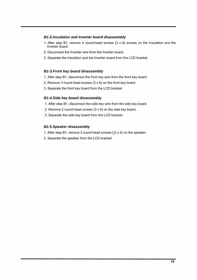
75
B1-2.Insulation and Inverter board disassembly 1. After step B1, remove 4 round-head screws (3 x 6) screws on the Insulation and the
Inverter board.
2. Disconnect the Inverter wire from the Inverter board.
3. Separate the insulation and the Inverter board from the LCD bracket.
B1-3.Front key board disassembly 1. After step B1, disconnect the front key wire from the front key board.
2. Remove 3 round-head screws (3 x 6) on the front key board.
3. Separate the front key board from the LCD bracket. B1-4.Side key board disassembly 1. After step B1, disconnect the side key wire from the side key board.
2. Remove 2 round-head screws (3 x 6) on the side key board.
3. Separate the side key board from the LCD bracket.
B1-5.Speaker disassembly 1. After step B1, remove 2 round-head screws ((3 x 4) on the speaker.
2. Separate the speaker from the LCD bracket.
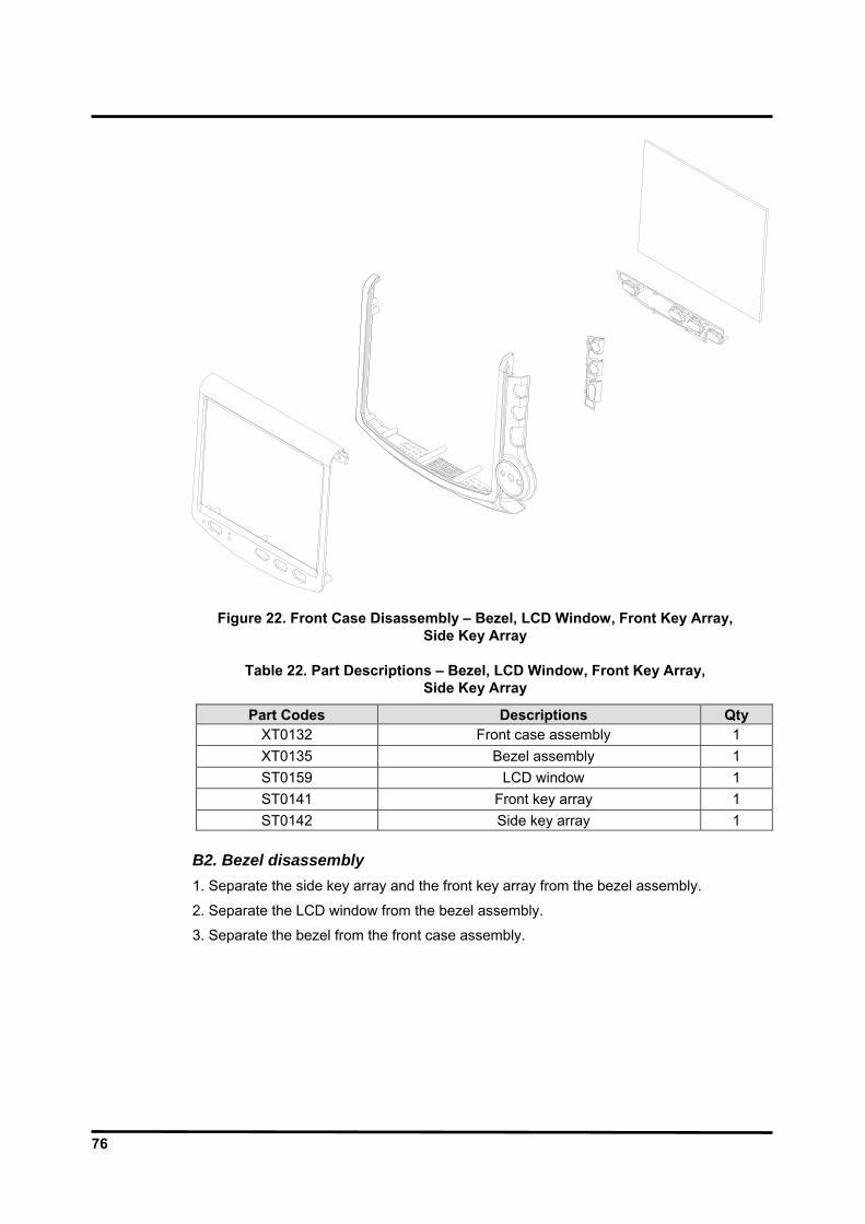
76
Figure 22. Front Case Disassembly – Bezel, LCD Window, Front Key Array, Side Key Array
Table 22. Part Descriptions – Bezel, LCD Window, Front Key Array,
Side Key Array
Part Codes Descriptions Qty XT0132 Front case assembly 1 XT0135 Bezel assembly 1 ST0159 LCD window 1 ST0141 Front key array 1 ST0142 Side key array 1
B2. Bezel disassembly 1. Separate the side key array and the front key array from the bezel assembly.
2. Separate the LCD window from the bezel assembly.
3. Separate the bezel from the front case assembly.

77
Rear Case Disassembly (C) This section describes the items that may be removed on the rear case assembly.
Figure 23. Rear Case Disassembly – Patient Sensor Case, Water Trap,
CO2 Absorber & Holder, AC Cord Clasp & Holder
Table 23. Part Descriptions – Patient Sensor Case, Water Trap, CO2 Absorber & Holder, AC Cord Clasp & Holder
Part Codes Descriptions Qty - IBP module 1
ST0154 Patient sensor case (with CO2 option) 1 ST0137 Patient sensor case (without CO2 option) 1 ST0143 AC cord clasp holder 1 ST4124 AC cord clasp 1 ST0156 CO2 absorber holder 1
C1. Patient Sensor Case disassembly 1. Pull the IBP module out to separate form the rear case assembly.
2. Disconnect the tubes connected to each connector.
3. Separate the patient sensor case from the rear case assembly
78
C2.Water Trap and CO2 Absorber disassembly 1. Separate the tubes connected to the water trap and CO2 absorber.
2. Separate the water trap and CO2 absorber from the rear case assembly.
3. Remove 3 tapping screw (3 x 20) from the water trap holder.
4. Separate the water trap holder from the water trap. Note: The water trap, water trap holder and CO2 absorber is included in the CO2 assembly.
(XM0008).
C3. AC Cord Clasp & Holder and CO2 Absorber Holder disassembly 5. Separate the AC cord clasp from the rear case assembly.
6. Remove 2 flat-head screw (4 x 10) from the AC cord clasp holder.
7. Separate the AC cord clasp holder from the rear case assembly.
8. Separate the CO2 absorber holder from the CO2 absorber.

79
Figure 24. Rear Case Disassembly – TRX-02 Module Option Cover, Recorder, Main Board
Table 24. Part Descriptions – TRX-02 Module Option Cover, Recorder, Main Board
Part Codes Descriptions Qty ST0147 TRX-02 module option cover 1 XM4020 Recorder module 1 ST0145 Recorder option cover SP1059 Main board 1
C4. TRX-02 module option cover disassembly
1. Remove 1 round-head screw (3 x 6) on the rear case assembly.
2. Separate the TRX-02 module option cover form the rear case assembly.
C5.Recorder disassembly 1. Remove 2 round-head screws (3 x 6) on the recorder.
2. Open the recorder door.
3. Pull out the recorder to remove from the rear case assembly.
*If no print option in, remove 2 screws on the recorder option cover, and then remove the recorder option cover.
C6.Main Board disassembly 1. Remove the ECG wire, TRX-02 and CO2 wire from the man board.
2. Remove 5 screws on the main board.
3. Remove the main board from the rear case assembly.

80
Figure 25. Rear Case Disassembly – ECG Board, SpO2 Module, CPU Module
Table 25. Part Descriptions – ECG Board, SpO2 Module, CPU Module
Part Codes Descriptions Qty SP1061 ECG board 1
- SpO2 module 1 SP1062 CPU module 1
C6-1.ECG Board disassembly 1. After step C8, remove 6 round-head screws (3 x 6) on the ECG board and the main
board to remove 3 supporters fastening the ECG board.
2. Separate the ECG board from the main board.
C6-2.SpO2 module disassembly 1. After step C8, remove 6 round-head screws (3 x 6) on the SpO2 module and the main
board to remove 3 supporters fastening the SpO2 module.
2. Remove the SpO2 module from the main board.
C6-3.CPU module disassembly 1. After step C8, remove 8 round-head screws (3 x 4) on the CPU module and the main
board to remove 4 supporters fastening the CPU module.
2. Remove the CPU module from the main board.

81
Figure 26. Rear Case Disassembly – NIBP Module, Hub Board, ECG Wire, CO2
Module
Table 26. Part Descriptions – NIBP Module, Hub Board, ECG Wire, CO2 Module
Part Codes Descriptions Qty - NIBP module 1
SP1060 Hub board 1 XM0008 EtCO2 assembly 1 SW0144 ECG wire (12 pin) 1 SW0142 TRX-02 wire (8 pin) 1 SW0146 CO2 wire (4 pin) 1
C7.NIBP module disassembly 1. Separate the NIBP module from the rear case assembly. C8.Hub Board disassembly 1. Remove the hub board from the rear case assembly. C9.ECG Wire disassembly 1. Remove 2 round-head screws (3 x 6) on the ECG wire.
2. Separate the ECG wire from the in-case assembly. C10.CO2 Module disassembly 1. Remove 3 round-head screws (2 x 5) on the CO2 board and 2 round-head screws (2 x
5) on the CO2 pump.
2. Remove the CO2 board and CO2 pump from the in-case assembly.
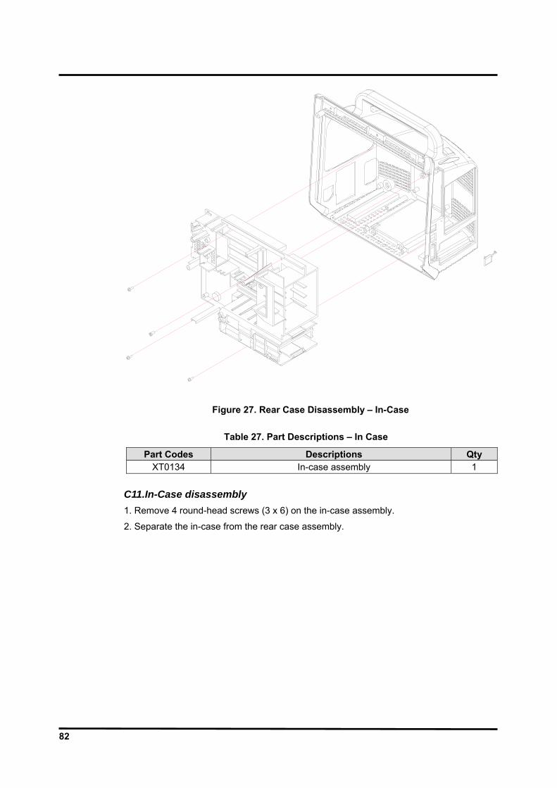
82
Figure 27. Rear Case Disassembly – In-Case
Table 27. Part Descriptions – In Case
Part Codes Descriptions Qty XT0134 In-case assembly 1
C11.In-Case disassembly 1. Remove 4 round-head screws (3 x 6) on the in-case assembly.
2. Separate the in-case from the rear case assembly.
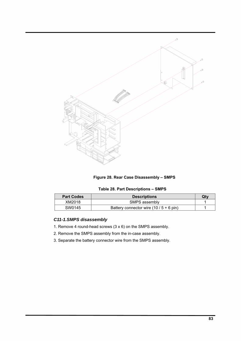
83
Figure 28. Rear Case Disassembly – SMPS
Table 28. Part Descriptions – SMPS
Part Codes Descriptions Qty XM2018 SMPS assembly 1 SW0145 Battery connector wire (10 / 5 + 6 pin) 1
C11-1.SMPS disassembly 1. Remove 4 round-head screws (3 x 6) on the SMPS assembly.
2. Remove the SMPS assembly from the in-case assembly.
3. Separate the battery connector wire from the SMPS assembly.

84
Figure 29. Rear Case Disassembly – VESA Bracket, Handle
Table 29. Part Descriptions – VESA Bracket, Handle
Part Codes Descriptions Qty XT0133 Rear case assembly 1 ST4119 VESA bracket 1 XT0138 Handle assembly 1
C12. VESA Bracket disassembly 1. Remove 5 flat-head screws (4 x 10) on the VESA bracket.
2. Remove the VESA bracket from the rear case assembly.
C13. Handle disassembly 1. Remove 4 round-head screws (4 x 6) on the handle assembly.
2. Remove the handle from the rear case assembly. 3. Remove the handle rubber from the handle assembly.

85
Figure 30. BP-S510 Exploded View

86
This page is intentionally left blank.
87
SPARE PARTS
WARNING: Follow local government ordinances and recycle instructions regarding disposal or recycling of device components, including batteries.
General
Spare parts, along with part numbers, are shown in Table 30. “Item No.” corresponds to the circled callout numbers in Figure 31.
Obtaining Replacement Parts
Omron Healthcare provides technical assistance information and replacement parts. To obtain replacement parts, contact your local supplier. Refer to parts by the part names and part numbers.

88
Figure 31. BP-S510 Exploded View – Spare Parts
Table 30. Spare Part List

89
Item Part Code Description 1 XT0132 Front case assembly 2 XT0133 Rear case assembly 3 XT0134 In-case assembly 4 XT0135 Bezel assembly 5 ST0136 Side key case 6 XT0138 Handle assembly 7 ST0139 Battery cover 8 ST0140 Knob (jog dial) 9 ST0141 Front key array
10 ST0142 Side key array 11 ST0143 AC cord clasp holder 12 ST0145 Recorder option cover 13 ST0147 TRX02 module option cover 14 ST0148 Gas module cover 15 ST0149 Water trap module option cover 16 ST0150 CO2 absorber option cover 17 ST0154 Patient sensor case (EtCO2 option) 18 ST0137 Patient sensor case (without EtCO2 option) 19 ST0156 CO2 absorber holder 20 ST4118 LCD bracket 21 ST4119 VESA bracket 22 ST0159 LCD window 23 ST0160 Alarm LED reflector 24 XM4020 Recorder module 25 SM4024 LCD (Mitsubishi) 26 SM4028 LCD (AUO) 27 XM2018 SMPS assembly 28 XM0008 CO2 assembly 29 SP1059 Main board 30 SP1060 Hub board 31 SP1061 ECG board 32 SP1062 CPU module 33 XP1063 Side key board 34 SP1064 Front key board 35 SP1065 Inverter board 36 - NIBP module 37 - IBP module 38 SM6010 Battery 39 SE9010 Speaker 40 ST4124 AC cord clasp 41 SW0140 Side key wire 42 SW0141 Front key wire 43 SW0142 TRX02 wire 44 SW0143 Inverter wire

90
Item Part Code Description 45 SW0144 ECG wire 46 SW0145 Battery connector wire 47 SW0146 CO2 wire 48 SW0147 LCD wire for Mitsubishi 49 SW0148 LCD wire for AUO 50 ST3034 Insulation 51 SA0062 Paper (50mm) - SB0042 Product Label - SB0047 Printer Label - SA7072 Operation Manual - SA7086 Service Manual
Note: You can use the assembly kit (SS8001) supplied by the manufacturer for screws,
washers and supporters. Contact your local supplier for more information.

91
PACKING FOR SHIPMENT General Instructions
To ship the monitor for any reason, follow the instructions in this section. Pack the monitor carefully. Failure to follow the instructions in this section may result in loss or damage not covered by the Omron Healthcare warranty. If the original shipping carton is not available, use another suitable carton;
Returning the BP-S510 monitor
Pack the monitor in its original shipping carton. If the original carton is not available, use a suitable carton with appropriate packing material to protect it during shipping.
Repacking In Original Carton If available, use the original carton and packing materials. Pack the monitor as follows: 1. Place the monitor and, if necessary, accessory items in original packaging.
2. Place in shipping carton and seal carton with packaging tape.
3. Label carton with shipping address and return address.
Repacking In a Different Carton
If the original carton is not available, use the following procedure to pack the monitor: 1. Place the monitor in a protective plastic bag against shock.
2. Locate a corrugated cardboard shipping carton with at least 20 kg/m2 bursting strength.
3. Fill the bottom of the carton with at least 7 cm of packing material.
4. Place the bagged unit on the layer of packing material and fill the box completely with packing material.
5. Seal the carton with packing tape.
6. Label the carton with the shipping address and return address.

92
This page is intentionally left blank.

93
SPECIFICATION
Display Screen Size 10.4” measured diagonally across the TFT-LCD screen Screen Type/Color Liquid Crystal Display (LCD) Color,
Cold Cathode Fluorescent Backlit Resolution 800 × 600 pixel Number of traces 4 or 6 waveforms
Controls
Standard Jog dial control; 7 soft buttons (NIBP start/stop, Home, NIBP interval, Alarm silence, Trend, Record, Power on/off)
Alarms
Categories Patient Status and System Status Priorities Low, Medium and High Priorities Notification Audible and Visual Setting Default and Individual Alarm Volume Level 45 to 85 dB
Physical Characteristics and Recorder
Instrument Dimensions 360 × 280 × 215 (mm) (W×H×D)
including a handle and excluding options and accessories Weight 5.5 kg excluding optional configurations and accessories Degree of protectionagainst electric shock
ECG: IBP(P1-P2): NIBP: SpO2: Temperature (T1-T2): Gas(CO2):
Type CF with defibrillator protectionType CF with defibrillator protectionType CF with defibrillator protectionType CF with defibrillator protectionType CF with defibrillator protection Type CF with defibrillator protection
Mode of Operation Continuous Classification: Class IIb (MDD Annex IX Rule10:MEDDEV 2.4/1 Rev.8)
Recorder (Optional) Type Thermal Weight 150 g Resolution 8 dot/mm Number of channels 1 to 2 channels Paper Type Thermal Paper Width 50 mm Paper Speeds 25.0 mm/s and 50.0 mm/s

94
Electrical Instrument
Power Requirements AC Mains 100-240V~50/60 Hz, 0.5-1.3A
Fuses q’ty 2, T6.3 A, 250 volts, (time-lag), IEC (5×20 mm) Battery
A battery typically provides operating time of 1 hour when fully charged with no printing, no external communication, no audible alarm sound and one NIBP measurement per 5 minutes at 25°C. Type Ni-MH Voltage/Capacity 12 V/ 3.8 Ampere-Hours Recharge Over 12 hours with monitor turned on/off Shelf Life 2 years, new battery fully-charged Compliance 91/157/EEC
Environmental Conditions
Operation Temperature 10°C to 40°C (50°F to 104°F) Humidity 15 % RH to 90% RH, non-condensing Altitude 500hPa to 1060hPa
Transport and Storage (in shipping container) Temperature −20°C to 60°C (−4°F to 140°F) Humidity 15 % RH to 95% RH, non-condensing Altitude 500hPa to 1060hPa Note: The system may not meet its performance specifications if stored or used
outside the specified temperature and humidity range.

95
Measurement Parameters ECG
Heart Rate Measurement Range 20 bpm ~ 250 bpm Accuracy ±3 bpm or ±5% whichever is greater Average Response Time 5 seconds (from 80 to120 bpm)
9 seconds (from 80 to 40 bpm) Tall T-wave Rejection Capability maximum T-wave amplitude 1.8 mV
ECG (Electrocardiograph) Leads 3 / 5 Lead
Lead I, II, III, aVR, aVL, aVF, V (Chest Lead) Lead Off Detection Detected and displayed Input Input Dynamic Range ±5 mV AC, ±300 mV DC Voltage range ±0.5 mV ~ ±5 mV Signal Width 40 ms ~ 120 ms (Q to S) Output Frequency Response (Bandwidth) Low Extend 0.05 Hz ~ 40 Hz Filter 0.5 Hz ~ 30 Hz Monitor 0.5 Hz ~ 40 Hz Respiration Rejection 1 Hz ~ 40 Hz ECG Size ×1/4, ×1/2, ×1, ×1.5, ×2 Display Sweep Speeds 12.5 mm/sec, 25.0 mm/sec, and 50.0 mm/sec Defibrillator Discharge Recovery
<5 sec per IEC60601-2-27
Respiration
im RR Technique Trans-thoracic impedance Range 0, 3 to 120 breaths/min Accuracy ±3 breaths/min Leads RA to LA Display Sweep Speeds 6.25 mm/s, 12.5 mm/s, 25.0 mm/s Lead Off Condition Detected and displayed
aw RR (Option)
Technique Nondispersive Infrared Spectroscopy Range 0 to 120 breaths/min Accuracy ±1 breath/min Display Sweep Speeds 6.25 mm/s, 12.5 mm/s, 25.0 mm/s

96
NIBP Pulse Rate
Pulse Rate Range Adult 40 bpm ~ 200 bpm Neonatal 40 bpm ~ 240 bpm
Pulse Rate Accuracy ±2 bpm or ±2%, whichever is greater NIBP (Non-Invasive Blood Pressure)
Technique Oscillometric Measurement Measurement modes MANUAL, AUTO and CONT MANUAL Mode Single measurement initiated by NIBP Start/Stop switch AUTO Mode Automatic BP measurements at intervals of 1, 2, 2.5, 3,
5, 10, 15, 20, 30, 45, 60, 90, 120, or 180 minutes CONT Mode Series of consecutive measurements for 5 minutes NIBP pressure measuring range Systolic pressure range Adult 60 mmHg ~ 250 mmHg
Neonatal 40 mmHg ~ 120 mmHg Diastolic pressure range Adult 40 mmHg ~ 200 mmHg
Neonatal 20 mmHg ~ 90 mmHg MAP pressure range Adult 45 mmHg ~ 235 mmHg
Neonatal 30 mmHg ~ 100 mmHg NIBP Accuracy Mean error and standard deviation per ANSI/AAMI
SP10:2002 Pressure Display Range 10 mmHg ~ 300 mmHg Pressure Display Accuracy ±3mmHg Initial Cuff Inflation Adult 120, 140, 160, 180, 200, 220, mmHg
(16.0, 18.7, 21.3, 24.0, 26.7, 29.3, kPa) Neonatal 80, 100, 120, 140 mmHg
(9.3, 12.0, 14.7, 16.0, 18.7 kPa) Automatic cuff deflation Measurement time exceeding 180s in adult/pediatric (90s
in neonatal) or maximum pressure value exceeding 300 mmHg in adult (150 mmHg in neonatal).
Overpressure protector 300 ±10 mmHg for Adult 150 ±5 mmHg for neonatal
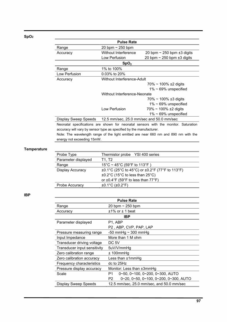
97
SpO2 Pulse Rate
Range 20 bpm ~ 250 bpm Accuracy Without Interference 20 bpm ~ 250 bpm ±3 digits
Low Perfusion 20 bpm ~ 250 bpm ±3 digits SpO2
Range 1% to 100% Low Perfusion 0.03% to 20% Accuracy Without Interference-Adult
70% ~ 100% ±2 digits 1% ~ 69% unspecified
Without Interference-Neonate 70% ~ 100% ±3 digits 1% ~ 69% unspecified
Low Perfusion 70% ~ 100% ±2 digits 1% ~ 69% unspecified
Display Sweep Speeds 12.5 mm/sec, 25.0 mm/sec and 50.0 mm/sec Neonatal specifications are shown for neonatal sensors with the monitor. Saturation accuracy will vary by sensor type as specified by the manufacturer. Note: The wavelength range of the light emitted are near 660 nm and 890 nm with the energy not exceeding 15mW.
Temperature
Probe Type Thermistor probe YSI 400 series Parameter displayed T1, T2 Range 15°C ~ 45°C (59°F to 113°F ) Display Accuracy ±0.1°C (25°C to 45°C) or ±0.2°F (77°F to 113°F)
±0.2°C (15°C to less than 25°C) or ±0.4°F (59°F to less than 77°F)
Probe Accuracy ±0.1°C (±0.2°F) IBP
Pulse Rate Range 20 bpm ~ 250 bpm Accuracy ±1% or ± 1 beat
IBP Parameter displayed P1, ABP
P2 , ABP, CVP, PAP, LAP Pressure measuring range -50 mmHg ~ 300 mmHg Input Impedance More than 1 M ohm Transducer driving voltage DC 5V Transducer input sensitivity 5uV/V/mmHg Zero calibration range ± 100mmHg Zero calibration accuracy Less than ±1mmHg Frequency characteristics dc to 25Hz Pressure display accuracy Monitor: Less than ±3mmHg Scale P1 0~50, 0~100, 0~200, 0~300, AUTO
P2 0~20, 0~50, 0~100, 0~200, 0~300, AUTO Display Sweep Speeds 12.5 mm/sec, 25.0 mm/sec, and 50.0 mm/sec

98
Capnography Parameter displayed EtCO2, InCO2 Range 0 mmHg ~ 100 mmHg; 0 kPa ~ 13.3 kPa; 0 % ~10 % CO2
STPD (standard temperature and pressure dry) Accuracy ±2mmHg or ±4%, whichever is greater Stability < 0.3 % (vol) CO2 /24hrs Rise Time 400 ms (average) Delay Time 1.8 (average) System Response 2.1 (average) Warm up time 3 minutes average Display Sweep Speeds 6.25mm/sec, 12.5 mm/sec and 25.0 mm/sec
Trends Types Graphical and Tabular Nonvolatile memory saves total 1500 data
saves at selected time interval saves alarm condition & error events saves NIBP Measuremets
Graphical Format Total 2 graphs a graph for NIBP, P1/P2, SpO2, T1/T2 parameters a graph for HR/PR, Resp, EtCO2 parameters User-selectable each parameter to be desired
Tabular Format One table for all parameters Display 8 lists Save Time Interval 30sec or 1, 2, 2.5, 5, 10, 15, 20, 30, 60 or 120 minutes
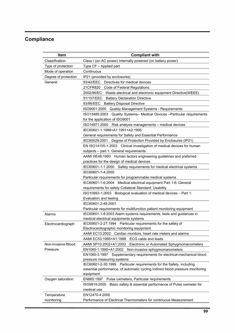
99
Compliance
Item Compliant with Classification Class I (on AC power) Internally powered (on battery power) Type of protection Type CF – Applied part Mode of operation Continuous Degree of protection IP21 (provided by enclosures) General 93/42/EEC Directives for medical devices 21CFR820 Code of Federal Regulations 2002/96/EC Waste electrical and electronic equipment Directive(WEEE) 91/157/EEC Battery Declaration Directive 93/86/EEC Battery Disposal Directive ISO9001:2000 Quality Management Systems - Requirements ISO13485:2003 Quality Systems– Medical Devices –Particular requirements
for the application of ISO9001 ISO14971:2000 Risk analysis managements – medical devices IEC60601-1:1988+A1:1991+A2:1995
General requirements for Safety and Essential Performance IEC60529:2001 Degree of Protection Provided by Enclosures (IP21) EN ISO14155-1:2003 Clinical investigation of medical devices for human
subjects – part 1: General requirements AAMI HE48:1993 Human factors engineering guidelines and preferred
practices for the design of medical devices IEC60601-1-1:2000 Safety requirements for medical electrical systems IEC60601-1-4:2000
Particular requirements for programmable medical systems IEC60601-1-6:2004 Medical electrical equipment Part 1-6: General
requirements for safety Collateral Standard: Usability ISO10993-1:2003 Biological evaluation of medical devices – Part 1:
Evaluation and testing IEC60601-2-49:2001
Particular requirements for multifunction patient monitoring equipment Alarms IEC60601-1-8:2003 Alarm systems requirements, tests and guidances in
medical electrical equipments systems Electrocardiograph IEC60601-2-27:1994 Particular requirements for the safety of
Electrocardiographic monitoring equipment AAMI EC13:2002 Cardiac monitors, heart rate meters and alarms AAMI EC53:1995+A1:1998 ECG cable and leads
AAMI SP10:2002+A1:2003 Electronic or Automated Sphygmomanometers Non-invasive Blood Pressure EN1060-1:1995+A1:2002 Non-invasive sphygmomanometers EN1060-3:1997 Supplementary requirements for electrical-mechanical blood
pressure measuring systems IEC60601-2-30:1999 Particular requirements for the Safety, including
essential performance, of automatic cycling indirect blood pressure monitoring equipment
Oxygen saturation EN865:1997 Pulse oximeters, Particular requirements ISO9919:2005 Basic safety & essential performance of Pulse oximeter for
medical use Temperature monitoring
EN12470-4:2000 Performance of Electrical Thermometers for continuous Measurement
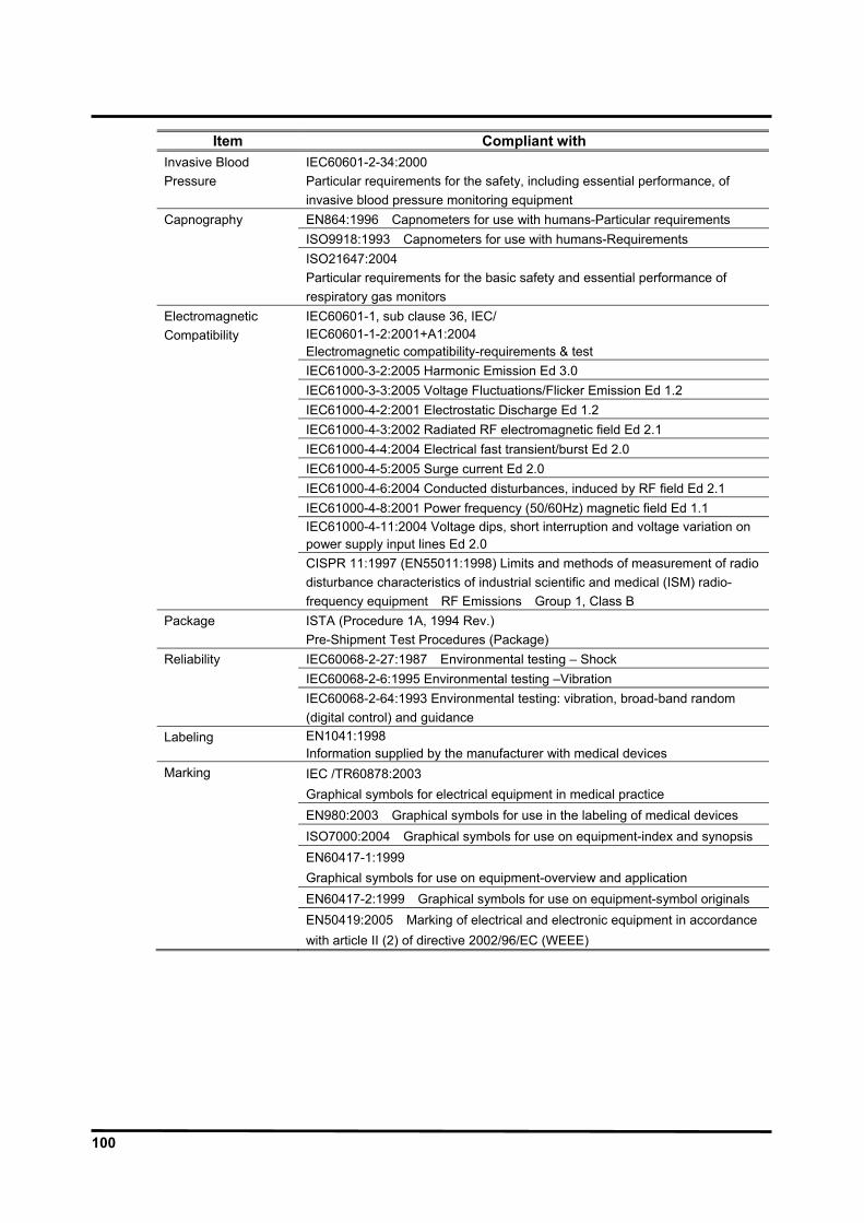
100
Item Compliant with Invasive Blood Pressure
IEC60601-2-34:2000 Particular requirements for the safety, including essential performance, of invasive blood pressure monitoring equipment
Capnography EN864:1996 Capnometers for use with humans-Particular requirements ISO9918:1993 Capnometers for use with humans-Requirements ISO21647:2004
Particular requirements for the basic safety and essential performance of respiratory gas monitors
Electromagnetic Compatibility
IEC60601-1, sub clause 36, IEC/ IEC60601-1-2:2001+A1:2004 Electromagnetic compatibility-requirements & test
IEC61000-3-2:2005 Harmonic Emission Ed 3.0 IEC61000-3-3:2005 Voltage Fluctuations/Flicker Emission Ed 1.2 IEC61000-4-2:2001 Electrostatic Discharge Ed 1.2 IEC61000-4-3:2002 Radiated RF electromagnetic field Ed 2.1 IEC61000-4-4:2004 Electrical fast transient/burst Ed 2.0 IEC61000-4-5:2005 Surge current Ed 2.0 IEC61000-4-6:2004 Conducted disturbances, induced by RF field Ed 2.1 IEC61000-4-8:2001 Power frequency (50/60Hz) magnetic field Ed 1.1 IEC61000-4-11:2004 Voltage dips, short interruption and voltage variation on
power supply input lines Ed 2.0 CISPR 11:1997 (EN55011:1998) Limits and methods of measurement of radio
disturbance characteristics of industrial scientific and medical (ISM) radio-frequency equipment RF Emissions Group 1, Class B
Package ISTA (Procedure 1A, 1994 Rev.) Pre-Shipment Test Procedures (Package)
Reliability IEC60068-2-27:1987 Environmental testing – Shock IEC60068-2-6:1995 Environmental testing –Vibration IEC60068-2-64:1993 Environmental testing: vibration, broad-band random
(digital control) and guidance Labeling EN1041:1998
Information supplied by the manufacturer with medical devices Marking IEC /TR60878:2003
Graphical symbols for electrical equipment in medical practice EN980:2003 Graphical symbols for use in the labeling of medical devices ISO7000:2004 Graphical symbols for use on equipment-index and synopsis EN60417-1:1999
Graphical symbols for use on equipment-overview and application EN60417-2:1999 Graphical symbols for use on equipment-symbol originals EN50419:2005 Marking of electrical and electronic equipment in accordance
with article II (2) of directive 2002/96/EC (WEEE)

101
SYSTEM PROCESSING System Overview
The BP-S510 monitor is a multi-function monitor for use on adult and neonatal patients; ECG, heart rate, non invasive blood pressures, arterial oxygen saturation, pulse rate, respiration rate, temperature, invasive blood pressure and capnography. In addition to monitoring and displaying the status of these physiological parameters, the instrument performs various microprocessor-programmed analytical functions;
Creating both visual and audible alarm signals when settable limits are violated; Creating and displaying warning/error messages when conditions are detected that
would degrade or prevent valid measurements; Creating and displaying graphical or tabular trend data; Providing input to an optional recorder for printout of current data or stored trend data.
The monitor is essentially a battery-powered instrument. An internal charging unit is designed to accept only an AC line voltage.
System Block Diagram
NIBP UNIT
SMPS UNIT
DC/DCAC/DC
Charger
HUB BoardPRINTER
UNITIBP UNIT
Main Board ECG & Respiration
Board
SpO2 UNIT
UART Interface
TRX02 Unit
PROCESSOR BOARD
Temperature Interface
EtCO2 UUNIT
TCP/IPInterface
USB Interface
Front Key Board
Side Key Board
Inverter Board
Battery Connector
Board
Isolation Region
S1 M1
I2
I1-1
I1-2
I1-3
Figure 32. System Block Diagram

102
Unit Description
Power unit: consists of power entry module, SMPS, battery charger, battery, external DC input and DC/DC unit.
Figure 33. Power Unit Block Diagram
Processor unit: consists of Samsung S3C2440 CPU, SDRAM, Boot ROM and Flash.
SDRAM
Flash Memory
Data
Boot/Source program, Trend/setup data
S3C2440ARM9 MCU
UART
RTC
LCD Controller
SPI
Watch Dog Timer
GPIO
SpO2 Unit
IOP UnitCoin Cell battery
LVDS Transmitter
A/D converter
Control SignalStatus InputUART
Communication data,
Figure 34. Process Unit Block Diagram

103
User-control unit: consists of jog dial, 6 functional button, optical encoder, power on indicator LED, Battery charging indicator LED and battery charging status indicator LED.
Figure 35. User-Control Unit Block Diagram
Sound unit: consists of 8bit PIC micom, 2-channel amplifiers and speaker.
Figure 36. Sound Unit Block Diagram
Communication unit : 4-channel UART
Figure 37. Communication Unit Block Diagram

104
GUI (graphic user interface) unit: consists of TFT LCD, inverter for backlit and internal video controller.
Figure 38. GUI Unit Block Diagram
Thermal Recorder unit: prints data records.
Figure 39. Thermal Recorder Unit Block Diagram
NIBP unit: measures non-invasive blood pressure data.
Figure 40. NIBP Unit Block Diagram

105
ECG unit: measures electrocardiographic waveform data.
Figure 41. ECG Unit Block Diagram
Respiration unit: measures respiration rate data.
Figure 42. Respiration Unit Block Diagram
SpO2 unit: measures oxygen saturation data.
Isolation DC/DC
Photo coupler SpO2 moduleS3C2440
DC +5V Isolation DC +5V, +12V
Patient Isolation
Figure 43. SpO2 Unit Block Diagram
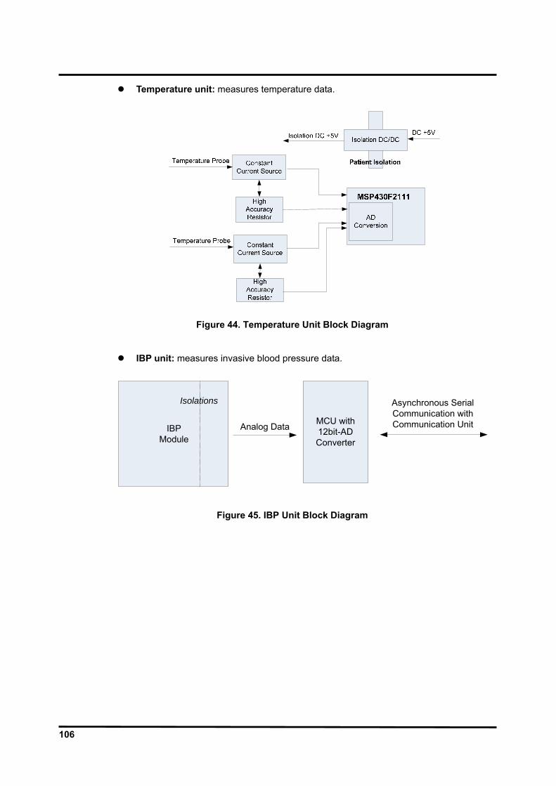
106
Temperature unit: measures temperature data.
Figure 44. Temperature Unit Block Diagram
IBP unit: measures invasive blood pressure data.
MCU with 12bit-ADConverter
IBPModule
Isolations
Analog Data
Asynchronous Serial Communication with Communication Unit
Figure 45. IBP Unit Block Diagram
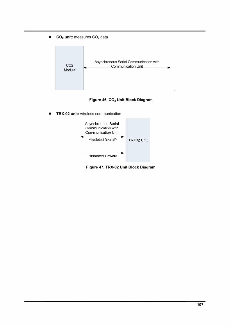
107
CO2 unit: measures CO2 data
CO2Module
Asynchronous Serial Communication with Communication Unit
.
Figure 46. CO2 Unit Block Diagram
TRX-02 unit: wireless communication
Figure 47. TRX-02 Unit Block Diagram
108
ECG Processing
The measurement of the skin surfaces electrocardiogram is based on the electrical signals on the skin surface, produced as the heart muscle contracts and relaxes. The signals are detected by electrodes placed on the patient body. The information on heart activity carried by these signals varies with the placing of the electrodes. The technique used in ECG senses the varying potential difference between two points at the skin surface which respond to the chemical actions of the muscular activity of the heart. Three electrodes are attached to the patient’s right arm (RA), left arm (LA) and left leg (LL). The varying potentials at these locations are cable-connected to the ECG circuit inputs where they are conditioned, and the difference of potential between two selected leads is digitized before transmitting through opto-isolators to the processor. The processor-installed algorithms operate on the signals to develop drivers for the graphic display and to compute the heart rate in beats per minute (bpm). In addition to the acquisition of the QRS waveform complex, the ECG input and subsequent signal processing computing circuitry perform a number of other functions:
They detect a lead-off condition if one of the electrode connections is disrupted. They detect the presence of pacemaker signals within the QRS waveform complex
of the ECG.
NIBP Processing
Overview The oscillometric technique does not use Korotkoff sounds to determine blood pressure. The oscillometric technique monitors the changes in cuff pressure caused by the flow of blood through the artery. The monitor inflates the cuff to a pressure that occludes the artery. Even when the artery is occluded, the pumping of the heart against the artery can cause small pressure pulses in the cuff baseline pressure. The monitor lowers cuff pressure at a controlled rate. As the cuff pressure goes down, blood starts to flow through the artery. The increasing blood flow causes the amplitude of the pressure pulses in the cuff to increase. These pressure pulses continue to increase in amplitude with decreasing cuff pressure until they reach a maximum amplitude at which point they begin to decrease with decreasing cuff pressure. The cuff pressure at which the pulse amplitude is the greatest is known as Mean Arterial Pressure (MAP). The manner in which the pulse amplitudes vary is often referred to as the pulse envelope. The envelope is an imaginary line that connects the peak of each pressure pulse and forms an outline. The shape of the envelope is observed by the monitor using a variety of techniques to determine the diastolic and systolic blood pressure.
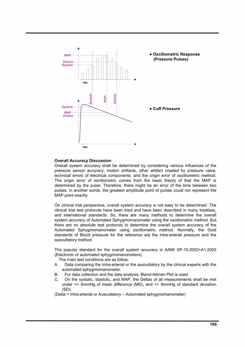
109
● Oscillometric Response
(Pressure Pulses) ● Cuff Pressure
Systole
Systole
MAP
Distole
MAPDistole
Dis
tole
MA
P
Syst
ole
TIME
TIME
Overall Accuracy Discussion Overall system accuracy shall be determined by considering various influences of the pressure sensor accuracy, motion artifacts, other artifact created by pressure valve, technical errors of electrical components, and the origin error of oscillometric method. The origin error of oscillometric comes from the basic theory of that the MAP is determined by the pulse. Therefore, there might be an error of the time between two pulses. In another words, the greatest amplitude point of pulses could not represent the MAP point exactly. On clinical trial perspective, overall system accuracy is not easy to be determined. The clinical trial test protocols have been tried and have been described in many treatises, and international standards. So, there are many methods to determine the overall system accuracy of Automated Sphygmomanometer using the oscillometric method. But, there are no absolute test protocols to determine the overall system accuracy of the Automated Sphygmomanometer using oscillometric method. Normally, the Gold standards of Blood pressure for the reference are the intra-arterial pressure and the auscultatory method. The popular standard for the overall system accuracy is AAMI SP-10:2002+A1:2003 (Electronic or automated sphygmomanometers). The main test conditions are as follow: A. Data comparing the Intra-arterial or the auscultatory by the clinical experts with the
automated sphygmomanometer. B. For data collection and the data analysis, Bland-Altman Plot is used. C. On the systolic, diastolic, and MAP, the Deltas of all measurements shall be met
under +/- 5mmHg of mean difference (MD), and +/- 8mmHg of standard deviation (SD).
(Delta = Intra-arterial or Auscultatory – Automated sphygmomanometer)
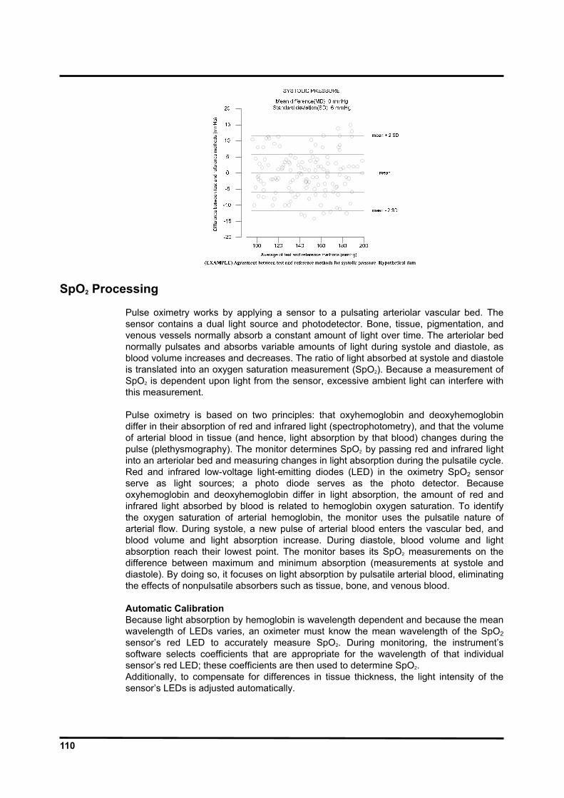
110
SpO2 Processing
Pulse oximetry works by applying a sensor to a pulsating arteriolar vascular bed. The sensor contains a dual light source and photodetector. Bone, tissue, pigmentation, and venous vessels normally absorb a constant amount of light over time. The arteriolar bed normally pulsates and absorbs variable amounts of light during systole and diastole, as blood volume increases and decreases. The ratio of light absorbed at systole and diastole is translated into an oxygen saturation measurement (SpO2). Because a measurement of SpO2 is dependent upon light from the sensor, excessive ambient light can interfere with this measurement. Pulse oximetry is based on two principles: that oxyhemoglobin and deoxyhemoglobin differ in their absorption of red and infrared light (spectrophotometry), and that the volume of arterial blood in tissue (and hence, light absorption by that blood) changes during the pulse (plethysmography). The monitor determines SpO2 by passing red and infrared light into an arteriolar bed and measuring changes in light absorption during the pulsatile cycle. Red and infrared low-voltage light-emitting diodes (LED) in the oximetry SpO2 sensor serve as light sources; a photo diode serves as the photo detector. Because oxyhemoglobin and deoxyhemoglobin differ in light absorption, the amount of red and infrared light absorbed by blood is related to hemoglobin oxygen saturation. To identify the oxygen saturation of arterial hemoglobin, the monitor uses the pulsatile nature of arterial flow. During systole, a new pulse of arterial blood enters the vascular bed, and blood volume and light absorption increase. During diastole, blood volume and light absorption reach their lowest point. The monitor bases its SpO2 measurements on the difference between maximum and minimum absorption (measurements at systole and diastole). By doing so, it focuses on light absorption by pulsatile arterial blood, eliminating the effects of nonpulsatile absorbers such as tissue, bone, and venous blood. Automatic Calibration Because light absorption by hemoglobin is wavelength dependent and because the mean wavelength of LEDs varies, an oximeter must know the mean wavelength of the SpO2 sensor’s red LED to accurately measure SpO2. During monitoring, the instrument’s software selects coefficients that are appropriate for the wavelength of that individual sensor’s red LED; these coefficients are then used to determine SpO2. Additionally, to compensate for differences in tissue thickness, the light intensity of the sensor’s LEDs is adjusted automatically.
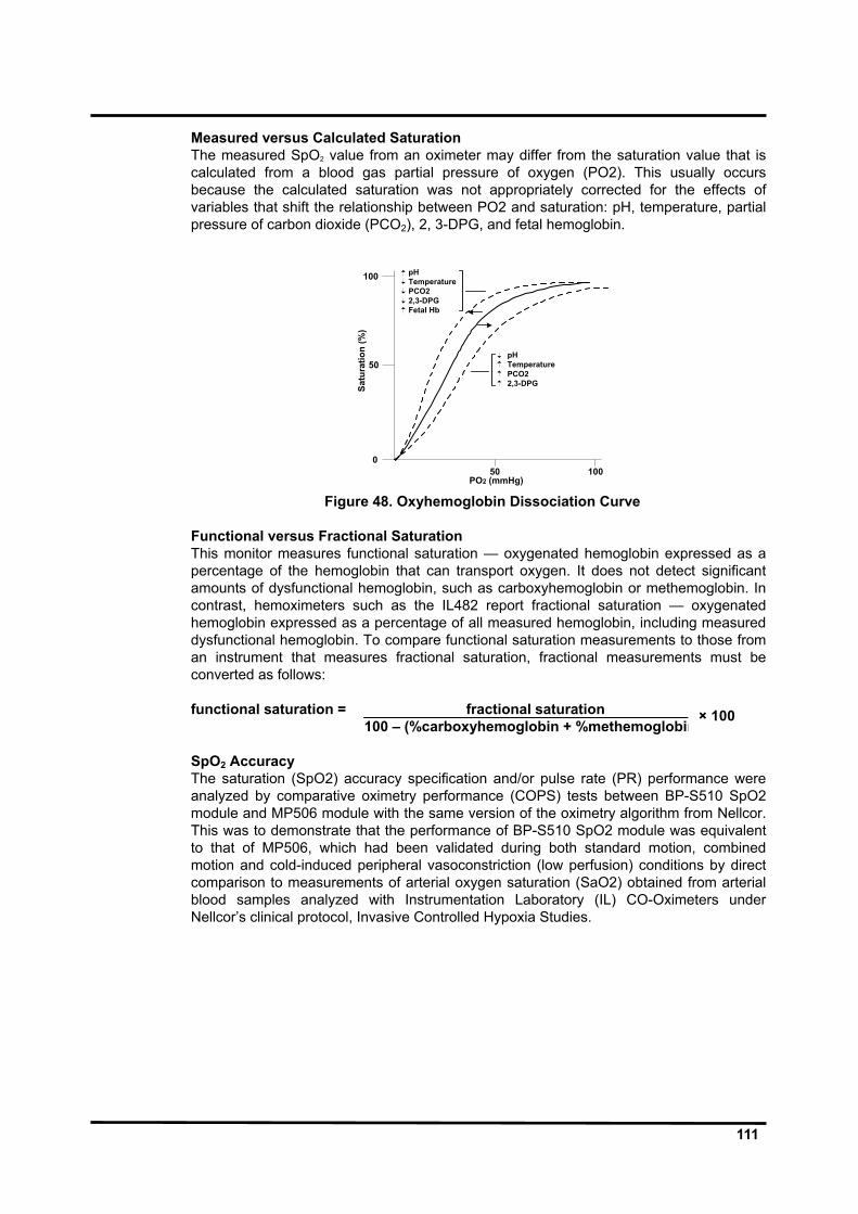
111
Measured versus Calculated Saturation The measured SpO2 value from an oximeter may differ from the saturation value that is calculated from a blood gas partial pressure of oxygen (PO2). This usually occurs because the calculated saturation was not appropriately corrected for the effects of variables that shift the relationship between PO2 and saturation: pH, temperature, partial pressure of carbon dioxide (PCO2), 2, 3-DPG, and fetal hemoglobin.
100
50
050 100
Satu
ratio
n (%
)
PO2 (mmHg)
pHTemperaturePCO22,3-DPGFetal Hb
pHTemperaturePCO22,3-DPG
Figure 48. Oxyhemoglobin Dissociation Curve
Functional versus Fractional Saturation This monitor measures functional saturation — oxygenated hemoglobin expressed as a percentage of the hemoglobin that can transport oxygen. It does not detect significant amounts of dysfunctional hemoglobin, such as carboxyhemoglobin or methemoglobin. In contrast, hemoximeters such as the IL482 report fractional saturation — oxygenated hemoglobin expressed as a percentage of all measured hemoglobin, including measured dysfunctional hemoglobin. To compare functional saturation measurements to those from an instrument that measures fractional saturation, fractional measurements must be converted as follows: functional saturation = fractional saturation 100 – (%carboxyhemoglobin + %methemoglobin) SpO2 Accuracy The saturation (SpO2) accuracy specification and/or pulse rate (PR) performance were analyzed by comparative oximetry performance (COPS) tests between BP-S510 SpO2 module and MP506 module with the same version of the oximetry algorithm from Nellcor. This was to demonstrate that the performance of BP-S510 SpO2 module was equivalent to that of MP506, which had been validated during both standard motion, combined motion and cold-induced peripheral vasoconstriction (low perfusion) conditions by direct comparison to measurements of arterial oxygen saturation (SaO2) obtained from arterial blood samples analyzed with Instrumentation Laboratory (IL) CO-Oximeters under Nellcor’s clinical protocol, Invasive Controlled Hypoxia Studies.
× 100

112
Respiration Processing
The respiration monitoring is designed to use the variation of this thoracic impedance. The chest contains various materials, ranging from bone to air. Each of these materials has different electrical properties and is located in a different portion of the chest. The materials of the chest vary in electrical resistivity (the amount of electrical resistance between opposite faces of a cube of that material), which is an important determinant of electrical impedance in the body. Two of the major components of the chest, blood and air, are at opposite ends of the scale. Furthermore, the volume of each of these materials varies with time over the cardiac and breathing cycles. The variation of the thoracic impedance is caused by the difference between air and blood in the thoracic impedance. Blood has relatively low resistivity, which varies over the cardiac cycle owing to changing blood volumes in the heart and in the vascular compartment. Air, on the other hand, has high electrical resistivity and hence impedance, and it undergoes wide volume changes in the lungs during normal breathing. i.e. the impedance of blood is 150 ohm/cm and the one of air is 5000 ohm/cm. The patient’s respiration is detected by using two of the three leads of the ECG electrodes (RA and LA, or RA and LL) and cable. The electrical impedance between a pair of electrodes is determined by dividing the voltage difference between the two electrodes by the current that passes between them. When the electrodes are placed on the actual structure, respective structures change. A low-level excitation signal is applied to these leads, and the variation of the thoracic impedance caused by the breathing is sensed and processed for display and measurement. This variation is processed to the voltage value for the measurement. In order to transfer the thoracic impedance by a transformer, it is used a minimum constant current of the sine wave carrier signal. The transferred thoracic impedance is changed to the voltage signal by using bridge circuit and differential amplifier. Then, ECG signal is removed by filter, and carrier frequency is removed by full wave rectifier and filter in order to extract only thoracic impedance in amplifying at the definite level of signal. This extracted thoracic impedance signal is used to measure the respiration by digital signal processing.
Temperature Processing
Measurement of patient temperature is accomplished by processing the signal from a probe containing a resistor whose resistance is temperature dependent. The class of such components is called thermistor. Temperature measurement used by the BP-S510 monitor based on a thermistor whose resistance is inversely proportional to its temperature. By measuring the thermistor’s resistance, its temperature can be calculated. The resistance of the thermistor is measured by passing a current through it and measuring the voltage developed across it. The BP-S510 monitor is designed to accept the signals from electrically isolated a range of temperature probes from YSI-400 series. The probes may be used for skin or rectal temperature measurement. Probes are furnished with a standard 10-feet lead; extension leads are available. The signal from the probe is conditioned by the monitor input circuitry, processed, and used to drive the numeric display.
113
Invasive Blood Pressure Processing The pressure transducer is connected to a pressure line which, by means of a catheter is invasively connected to the patients blood stream. The force of movement of the blood in the patients vessels in transported by the fluid column n the pressure line to the transducer. This movement cause an electrical signal to be generated which is then amplified to display the pressure wave and the numeric for the systolic, diastolic and mean pressure values. The blood pressure is influenced by the respiratory system. This occurs in spontaneous breathing patients, but is ore apparent in positive pressure ventilated patients. To reduce this respiration artifact the module uses a variable weight filter technique in the processing of the pressure values.
Capnography Processing
The capnography parameter provides the continuous, non-invasive monitoring of sidestream end-tidal carbon dioxide (EtCO2), inspired carbon dioxide (InCO2), and respiration rate (RR). The measured values for capnography (EtCO2, InCO2 and RR) are displayed in the CO2 parameter box and a CO2 waveform can be continuously displayed. Nitrous oxide compensation is selectable.


