81
Applicaon Guidelines for Photovoltaic Laminates
Application Guidelines for Photovoltaic Laminates
AA6 3654‐02
Headquarters Information
Global Headquarters
3800 Lapeer Road
Auburn Hills, MI 48326 USA
Toll‐Free: 1.800.843.3892
Phone: 1.248.475.0100
Fax: 1.248.364.0510
Email: info@uni‐solar.com
Web: http://www.uni‐solar.com
Application Guidelines for Photovoltaic Laminates
Document Version: 2.0
Release Date: January 2012
Copyright
© 2011 United Solar Ovonic LLC. All rights reserved.
Disclaimer of Liability
The information contained in this document is based on United Solar Ovonic’s knowledge and experience, but such information and suggestions do not constitute a warranty expressed or implied. The methods of installation, use, and maintenance of roofing surfaces are beyond the control of United Solar Ovonic (USO).
USO assumes no responsibility and expressly disclaims liability for any loss, damage, or expense associated with the use, installation, and/or operation of its solar systems. Any liability of United Solar Ovonic is strictly limited to the Limited Warranty.
USO reserves the right to make changes to product specifications and this document without notice. The content of this document was current to the time of publication.
Contact
For further information about United Solar Ovonic products, email USO at info@uni‐solar.com.
If you have questions or need support for specific roof PV system applications, contact your local UNI‐SOLAR office, referring to the contact information above.
Application Guidelines for Photovoltaic Laminates Table of Contents
AA6 3654‐02 i
Table of Contents
Scope of this Document .......................................................................................................... iv
Additional UNI‐SOLAR Documentation .................................................................................... v
Definitions and Acronyms ....................................................................................................... v
1 USO Photovoltaic Laminate Description .............................................................................. 1
2 Application Descriptions ..................................................................................................... 3
2.1 Direct Bond to Single‐Ply Membrane Roofs ........................................................................ 5
2.2 Bonding to Removable Single‐Ply Membranes .................................................................... 8
2.3 Direct Bond to Standing Seam Metal Roofs ...................................................................... 13
2.4 Standing Seam Metal Roofs Not Suitable for Direct Bond ................................................. 17
2.5 Corrugated Metal Roofs ................................................................................................... 20
2.6 Bonding to Modified Bitumen Roofs ................................................................................. 23
2.7 PowerTilt for Commercial Roofs ....................................................................................... 25
3 Rooftop Array Design Considerations ............................................................................... 31
3.1 Setbacks ........................................................................................................................... 31
3.2 Shading ............................................................................................................................ 32
3.3 Fire Code Requirements ................................................................................................... 33
4 Energy Modeling ............................................................................................................... 34
4.1 Energy Yield ..................................................................................................................... 34
4.2 Performance Modeling ..................................................................................................... 34
4.3 PV Modeling Software ...................................................................................................... 34
4.4 PVSyst Modeling Guidelines ............................................................................................. 35
5 Wire Management Systems .............................................................................................. 41
5.1 PVC WMS ......................................................................................................................... 41
5.2 Wire Mesh Cable Tray ...................................................................................................... 43
5.3 Custom Wireways ............................................................................................................ 44
6 Construction Overview and Scheduling ............................................................................. 48
6.1 Handling and Storage ....................................................................................................... 48
6.2 Logistics ........................................................................................................................... 48
6.3 Loading and Sequencing ................................................................................................... 49
6.4 Procurement .................................................................................................................... 50
6.5 Installation of Laminates .................................................................................................. 50
6.6 Electrical Activities ........................................................................................................... 51
Application Guidelines for Photovoltaic Laminates Table of Contents
AA6 3654‐02 ii
6.7 Commissioning ................................................................................................................. 51
6.8 Scheduling ....................................................................................................................... 51
7 Application Certifications .................................................................................................. 53
7.1 UL 1703 Flat‐Plate PV Modules and Panels ....................................................................... 53
7.2 ICC AC‐365 Acceptance Criteria for BIPV Roof Modules and Panels .................................. 53
7.3 CEC SB1 Guidelines for California’s Solar Electric Incentive Programs ............................... 54
7.4 IEC 61646 Thin‐film Terrestrial PV Modules and IEC 61730 and PV Module Safety Qualification ........................................................................................................................... 54
7.5 Korea: KEMCO Korean Energy Management Corporation ................................................. 54
7.6 Brazil: IEE‐USP .................................................................................................................. 54
7.7 Puerto Rico: AEE .............................................................................................................. 55
7.8 United Kingdom: MCS Microgeneration Certification Scheme .......................................... 55
Appendix A: PowerBond Estimating Reference ................................................................... 56
A.1 Project Description .......................................................................................................... 56
A.2 Estimating Data ................................................................................................................ 56
Appendix B: PowerMembrane Estimating Reference .......................................................... 57
B.1 Project Description .......................................................................................................... 57
B.2 Estimating Data ................................................................................................................ 57
Appendix C: PowerTilt Estimating Reference Guide ............................................................ 59
C.1 Project Description .......................................................................................................... 59
C.2 Estimating Data ................................................................................................................ 60
C.3 Estimating Assumptions, Exclusions, and Clarifications .................................................... 60
Appendix D: Sample Schedule ............................................................................................. 62
Appendix E: Application Selection Flowchart ...................................................................... 67
Application Guidelines for Photovoltaic Laminates Table of Figures
AA6 3654‐02 iii
Table of Figures
Figure 1: UNI‐SOLAR Laminates .................................................................................................................... 1 Figure 2: Core Technology ............................................................................................................................ 2 Figure 3: Direct Bond to Membrane Roof Sample Array Layout .................................................................. 6 Figure 4: Reference Project Photo for Direct Bond to Single‐Ply Membrane Roofs .................................... 8 Figure 5: 10' Wide PVL Power Membrane Detail—7 UNI‐SOLAR PVL .......................................................... 9 Figure 6: 8' Wide ePVL PowerMembrane Detail—6 UNI‐SOLAR ePVL ......................................................... 9 Figure 7: 10' Wide ePVL PowerMembrane Detail—7 UNI‐SOLAR ePVL ..................................................... 10 Figure 8: PowerMembrane Sample Array Layout ....................................................................................... 11 Figure 9: Reference Project Photo for Bonding to Removable Single‐Ply Membranes .............................. 13 Figure 10: Example of Lap Seams in Metal Roofing .................................................................................... 15 Figure 11: Direct Bond to Standing Seam Metal Roof Sample Array Layout .............................................. 16 Figure 12: Reference Project Photo for Direct Bond to Standing Seam Metal Roofs ................................. 17 Figure 13: Standing Seam Panels Installed Over Existing Metal Roof ........................................................ 18 Figure 14: Typical Z Purlin Profile ................................................................................................................ 19 Figure 15: S‐5! Seam Clamp Detail .............................................................................................................. 19 Figure 16: Reference Project Photo for Standing Seam Metal Roofs Not Suitable for Direct Bond .......... 20 Figure 17: New Standing Seam Roof Over Existing Metal Deck ................................................................. 22 Figure 18: Reference Project Photo for Corrugated Metal Roofs ............................................................... 23 Figure 19: Sample Array Layout on Modified Bitumen Roof ...................................................................... 24 Figure 20: Reference Project Photo for Bonding to Modified Bitumen Roofs ........................................... 25 Figure 21: PowerTilt Sample Array Layout .................................................................................................. 26 Figure 22: Sample PowerTilt Installation Sequencing Plan ......................................................................... 27 Figure 23: Sample PowerTilt Logistics Sequencing Plan ............................................................................. 27 Figure 24: Reference Project Photo for PowerTilt for Commercial Roofs .................................................. 30 Figure 25: Building Rendering with Solar Design Considerations Identified .............................................. 31 Figure 26: Sample Shading Analysis Tool Output ....................................................................................... 32 Figure 27: Shading Analysis Inserted on Roof Plan ..................................................................................... 33 Figure 28: PowerTilt "Unlimited Sheds" Configuration in PVSyst ............................................................... 36 Figure 29: PVSyst Thermal Loss Parameter Input Screenshot .................................................................... 39 Figure 30: PVC WMS Installation ................................................................................................................ 42 Figure 31: Uncovered Wire Mesh Cable Tray – Installation in Progress ..................................................... 43 Figure 32: Covered Wire Mesh Cable Tray with Roof Attachment Detail .................................................. 44 Figure 33: Custom Wireway Installation Matching Existing Metal Roof .................................................... 45 Figure 34: Hat Channel Profile Wire Cover ................................................................................................. 45 Figure 35: Custom Wire Channel Profiles ................................................................................................... 46 Figure 36: Custom Wire Channel Installation Detail ................................................................................... 46 Figure 37: Sample Site Logistics Plan .......................................................................................................... 49 Figure 38: Sample Work Sequencing Plan .................................................................................................. 50 Figure 39: Installed UNI‐SOLAR PowerMembrane Array ............................................................................ 58 Figure 40: Installation of PowerMembrane in Progress ............................................................................. 58 Figure 41: Installed PowerTilt Array ............................................................................................................ 60
Application Guidelines for Photovoltaic Laminates Scope of this Document
AA6 3654‐02 iv
Scope of this Document
This document is a desktop reference for UNI‐SOLAR® customers to support the development, design,
construction, and estimation of rooftop photovoltaic projects involving UNI‐SOLAR photovoltaic
laminates. The design notes and examples, labor case studies for estimations, energy modeling
guidelines, and other material in this document are intended to be used as a reference for sales
professionals, engineers, estimators, and construction personnel working on UNI‐SOLAR projects.
The guidelines and information contained herein support, but do not replace or supersede, the
specifications of the UNI‐SOLAR installation guides. The installation guides should be considered the
specifications to which a UNI‐SOLAR installation must adhere for the UNI‐SOLAR Limited Product and
Performance Warranty to apply.
Visit www.uni‐solar.com/resource‐center for the latest versions of our installation guides.
Application Guidelines for Photovoltaic Laminates Additional Uni‐Solar Documentation
AA6 3654‐02 v
Additional UNI‐SOLAR Documentation Additional UNI‐SOLAR documentation, including documentation referred to in this document, can be
found in our Resource Center at www.uni‐solar.com/resource‐center. Documents available in the
Resource Center include:
PVL / PowerTiltTM Installation Manuals:
- PVL Installation Guide – Metal Roofs (PVL)
Detailed application instructions of PVL to Metal roofs
Termination (Wiring) Options for PVL on Metal Roofs
- PVL Installation Guide – Membrane Roofs (PVL)
Detailed application instructions of PVL to Membrane roofs
Wire Management System Construction Procedures
- PowerTilt Installation Guide
PowerTilt – Mechanical Assembly
Array Assembly
System Grounding
Enhanced PVL (ePVL) Manuals
- Bonding and Installation Manual
Site Preparation
Safety Procedures
Recommended Tools & Equipment
- Electrical Design Manual
Inverter Selection
System Wiring
Electrical Installation Procedures
- Operation and Maintenance Manual
Maintenance Verifications
Cleaning Process
Inspection
Approved roofing substrates list
List of roofing substrates deemed compatible with PVL and ePVL
UNI‐SOLAR® Photovoltaic Laminates Limited Product and Power Output Warranty
Detailed description of our 25 year warranty
Marketing Collateral
Brochures
Product Data Sheets
Application Guidelines for Photovoltaic Laminates Definitions and Acronyms
AA6 3654‐02 vi
Definitions and Acronyms
The following definitions are designed to help you understand any unique terminology and acronyms
this document may use.
A‐Si: An acronym for amorphous silicon solar technology.
Approved Substrate: A building material, typically a roofing material, that has been tested by UNI‐
SOLAR personnel and is listed on the Approved Substrates list.
Array: A group of modules wired together, in a series and/or in parallel, to form an array of solar
modules.
Balance of Systems (BOS): The parts of a photovoltaic (PV) system other than the array. Some examples
include switches, controls, meters, power conditioning equipment, supporting structure for the array,
and storage components.
BIPV: An acronym for building integrated photovoltaic.
EPDM: An acronym for ethylene propylene diene monomer.
ETFE: An acronym for ethylene tetrafluoroethylene.
ICC: An acronym for International Codes Council.
Laminate: A flexible PV module manufactured by encapsulating the cell through a lamination process.
Module (Photovoltaic): PV modules are manufactured and assembled using solar cells, interconnect
wire, bypass diodes, encapsulant (which is a top cover over the solar cells) and a protective back sheet
behind the solar cells. Most solar modules also include a frame around the edges of the back sheet/top
cover assembly. Together, all of these components form the solar PV module.
NOA: An acronym for notice of acceptance.
NOCT: An acronym for normal operating cell temperature.
OSHA: An acronym for Occupational Safety and Health Association.
Photovoltaic (PV): The direct conversion of light into electrical energy.
Power Density: The ratio of the power available from a battery to its mass (W/kg) or volume (W/l).
PowerMembrane: A UNI‐SOLAR solar PV configuration in which multiple PV laminates are adhesively
bonded to a large (roughly 10’ x 20’) sheet of single‐ply roofing membrane. This assembly is then
Application Guidelines for Photovoltaic Laminates Definitions and Acronyms
AA6 3654‐02 vii
perimeter‐bonded to a single‐ply roof membrane. This system provides for solar PV system removal
without damaging the primary roofing system.
PVC: An acronym for polyvinylidene chloride.
SREC: An acronym for solar renewable energy credit.
TPO: An acronym for thermoplastic olefin.
Thin Film: A very thin layer of material formed on a substrate.
UL: An acronym for Underwriters Laboratory.
UV: An acronym for ultra‐violet.
WMS: An acronym for wire management system.
Application Guidelines for Photovoltaic Laminates USO Photovoltaic Laminate Description
AA6 3654‐02 1
1 USO Photovoltaic Laminate Description
UNI‐SOLAR manufactures photovoltaic (PV) laminates known as PVLs or ePVLS. The e in ePVL represents
enhanced PVL, which is the latest generation product. The ePVL product line possesses several
enhancements including:
More robust encapsulation
Decreased width and length, resulting in power density increases
MC4 electrical connectors with built‐in strain relief
UNI‐SOLAR’s unique amorphous silicon PV technology is comprised of a thin (less than 1 micron thick)
layer of silicon deposited on thin stainless steel substrate. This cell structure is encapsulated by durable
plastics and is warranted for 25 years.
Figure 1: UNI‐SOLAR Laminates
Application Guidelines for Photovoltaic Laminates USO Photovoltaic Laminate Description
AA6 3654‐02 2
Figure 2: Core Technology
Access the UNI‐SOLAR Web site at www.uni‐solar.com for more information.
Application Guidelines for Photovoltaic Laminates Application Descriptions
AA6 3654‐02 3
2 Application Descriptions
This chapter provides detailed descriptions for the following UNI‐SOLAR applications:
Direct bond to single‐ply membrane roofs
Bonding to removable single‐ply membranes
Direct bond to standing seam metal roofs
Standing seam metal roofs not suitable for direct bond
Corrugated metal roofs
Bonding to modified bitumen roofs
PowerTilt for commercial roofs
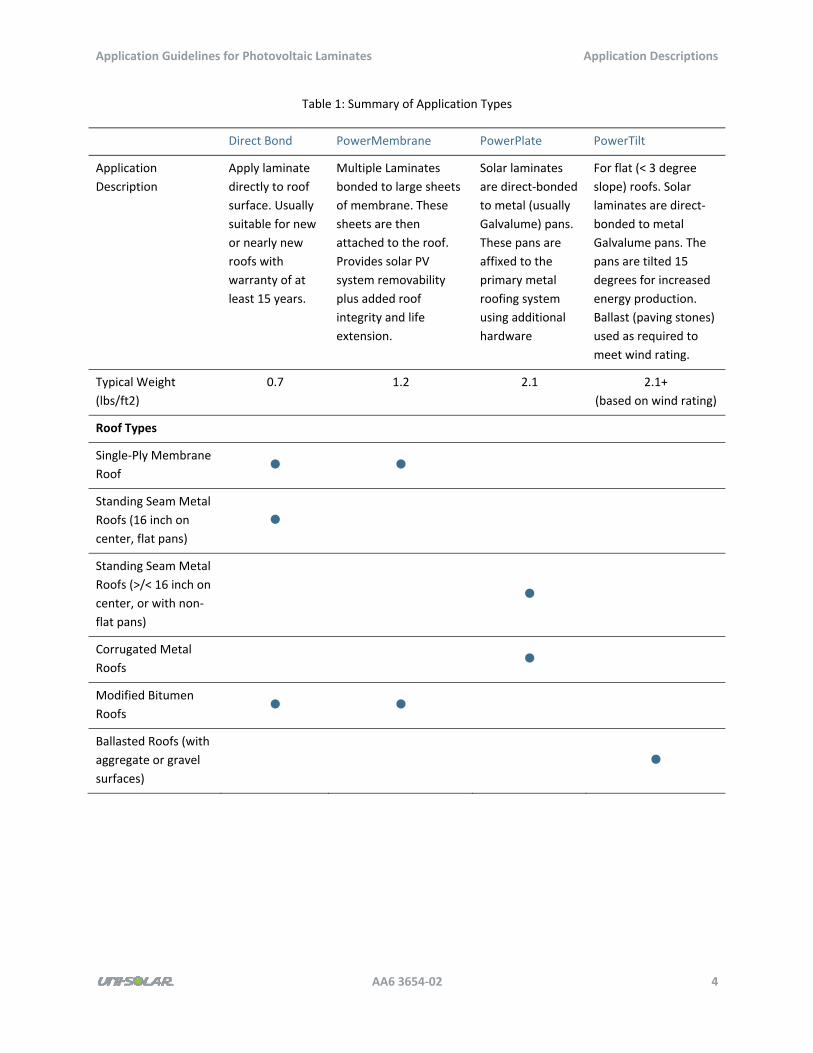
Table 1 (on the next page) provides a summary of the application types.
Application Guidelines for Photovoltaic Laminates Application Descriptions
AA6 3654‐02 4
Table 1: Summary of Application Types
Direct Bond PowerMembrane PowerPlate PowerTilt
Application
Description
Apply laminate
directly to roof
surface. Usually
suitable for new
or nearly new
roofs with
warranty of at
least 15 years.
Multiple Laminates
bonded to large sheets
of membrane. These
sheets are then
attached to the roof.
Provides solar PV
system removability
plus added roof
integrity and life
extension.
Solar laminates
are direct‐bonded
to metal (usually
Galvalume) pans.
These pans are
affixed to the
primary metal
roofing system
using additional
hardware
For flat (< 3 degree
slope) roofs. Solar
laminates are direct‐
bonded to metal
Galvalume pans. The
pans are tilted 15
degrees for increased
energy production.
Ballast (paving stones)
used as required to
meet wind rating.
Typical Weight
(lbs/ft2)
0.7 1.2 2.1 2.1+
(based on wind rating)
Roof Types
Single‐Ply Membrane
Roof
Standing Seam Metal
Roofs (16 inch on
center, flat pans)
Standing Seam Metal
Roofs (>/< 16 inch on
center, or with non‐
flat pans)
Corrugated Metal
Roofs
Modified Bitumen
Roofs
Ballasted Roofs (with
aggregate or gravel
surfaces)
Application Guidelines for Photovoltaic Laminates Application Descriptions
AA6 3654‐02 5
2.1 Direct Bond to Single‐Ply Membrane Roofs
The UNI‐SOLAR application direct bond to single‐ply membrane roofs consists of UNI‐SOLAR laminates
installed directly to a single‐ply roof membrane. Laminates are field‐applied to an approved membrane
using any of the primers specified on the Approved Substrates list, in accordance with all specifications
of the installation guide.
This section encompasses direct bond to the waterproofing layer of a roof and also applies to bonding to
a secondary layer of roofing membrane installed over the existing roof. The secondary layer may be
required for roof warranty purposes and is generally installed in large sections, and these application
guidelines apply to that installation practice when the laminates are installed to the membrane on the
roof. Installing the laminates to membrane before installing the membrane to the roof is covered in the
next section.
Applicable UNI‐SOLAR products include the PVL and ePVL series.
2.1.1 Applicable Roof Types
You can apply the UNI‐SOLAR PVL product to the following types of single‐ply membrane roofs:
Thermoplastic olefin (TPO)
Ethylene propylene diene monomer (EPDM)
The roof substrate must be listed on the UNI‐SOLAR Approved Substrates list.
2.1.2 Design Notes
UNI‐SOLAR modules must be located such that all requirements of the installation guide are met,
including avoiding areas of ponding water on the roof and not installing UNI‐SOLAR laminates over
seams in the roofing membrane.
2.1.3 Roofing Considerations
Single‐ply roofing is typically installed by rolling out the waterproofing membrane over the roof
assembly. Roof membrane rolls are 100‐150’ long and are most commonly 10’ wide, but can vary
between 6’ and 150’ wide. At the seam between two sections of membrane the two edges are sealed
with a heat weld or seam tape. UNI‐SOLAR recommends that you identify and avoid these seams in the
design of the UNI‐SOLAR array.
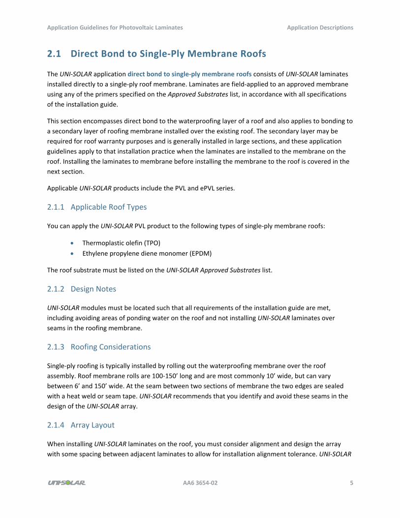
2.1.4 Array Layout
When installing UNI‐SOLAR laminates on the roof, you must consider alignment and design the array
with some spacing between adjacent laminates to allow for installation alignment tolerance. UNI‐SOLAR
Application Guidelines for Photovoltaic Laminates Application Descriptions
AA6 3654‐02 6
recommends a minimum of 0.25” spacing, with 0.5” providing additional tolerance when space is
available.
You must provide spacing for a wire management system (WMS) between the ends of two laminates,
where the terminals and wire leads are located. The chapter Wire Management Systems, which starts
on page 41, provides details on various wire management solutions; however, 5” is the required spacing
for the specialty PVC WMS and is a recommended spacing for baseline design purposes. Ensure that
final design documentation complies with all requirements of the Installation Manuals, including
application of the strain relief pad for the PVL series modules.
Figure 3: Direct Bond to Membrane Roof Sample Array Layout
2.1.5 Handling and Installation Notes
All specifications and requirements of the UNI‐SOLAR installation guides apply to the installation of the
UNI‐SOLAR laminates. During installation, be sure to handle and transport the laminates appropriately.
Once laminates are installed on the roof, minimize any foot traffic over the array. If personnel must walk
on the laminates, wear clean soft soled shoes and walk on the center on the laminate. Do not place
tools and material handling equipment (roof carts) on, or allow them to run across, the array.
When planning an installation, loading and sequence of work are critical to ensure that equipment and
personnel are not required to access work areas by crossing over installed product. Refer to the chapter
Construction Overview and Scheduling, which starts on page 48, for more details.
Application Guidelines for Photovoltaic Laminates Application Descriptions
AA6 3654‐02 7
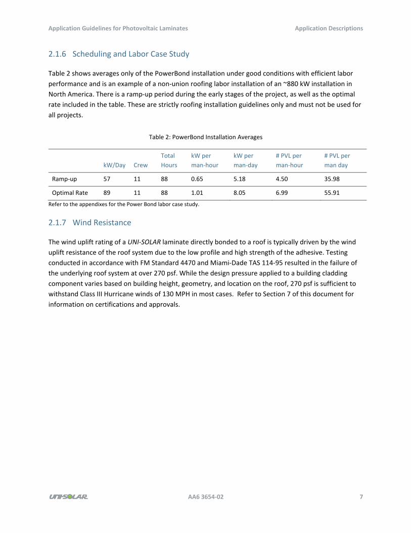
2.1.6 Scheduling and Labor Case Study
Table 2 shows averages only of the PowerBond installation under good conditions with efficient labor
performance and is an example of a non‐union roofing labor installation of an ~880 kW installation in
North America. There is a ramp‐up period during the early stages of the project, as well as the optimal
rate included in the table. These are strictly roofing installation guidelines only and must not be used for
all projects.
Table 2: PowerBond Installation Averages
kW/Day Crew
Total
Hours
kW per
man‐hour
kW per
man‐day
# PVL per
man‐hour
# PVL per
man day
Ramp‐up 57 11 88 0.65 5.18 4.50 35.98
Optimal Rate 89 11 88 1.01 8.05 6.99 55.91
Refer to the appendixes for the Power Bond labor case study.
2.1.7 Wind Resistance
The wind uplift rating of a UNI‐SOLAR laminate directly bonded to a roof is typically driven by the wind
uplift resistance of the roof system due to the low profile and high strength of the adhesive. Testing
conducted in accordance with FM Standard 4470 and Miami‐Dade TAS 114‐95 resulted in the failure of
the underlying roof system at over 270 psf. While the design pressure applied to a building cladding
component varies based on building height, geometry, and location on the roof, 270 psf is sufficient to
withstand Class III Hurricane winds of 130 MPH in most cases. Refer to Section 7 of this document for
information on certifications and approvals.
Application Guidelines for Photovoltaic Laminates Application Descriptions
AA6 3654‐02 8
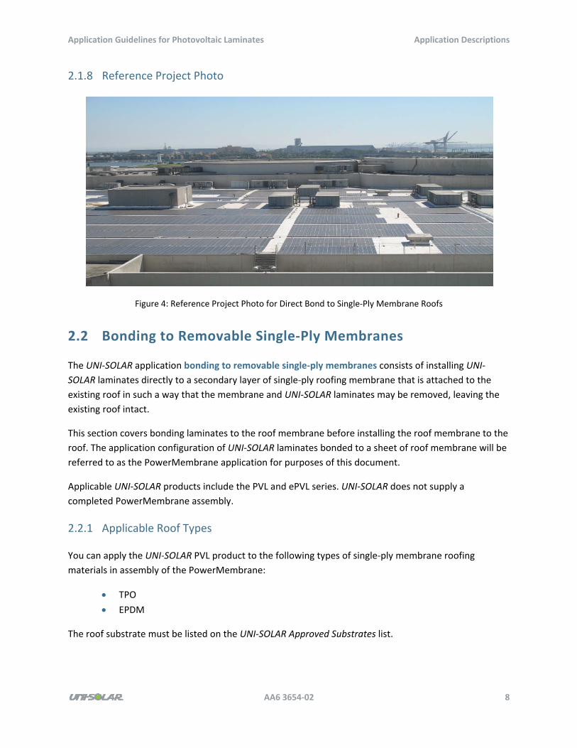
2.1.8 Reference Project Photo
Figure 4: Reference Project Photo for Direct Bond to Single‐Ply Membrane Roofs
2.2 Bonding to Removable Single‐Ply Membranes
The UNI‐SOLAR application bonding to removable single‐ply membranes consists of installing UNI‐
SOLAR laminates directly to a secondary layer of single‐ply roofing membrane that is attached to the
existing roof in such a way that the membrane and UNI‐SOLAR laminates may be removed, leaving the
existing roof intact.
This section covers bonding laminates to the roof membrane before installing the roof membrane to the
roof. The application configuration of UNI‐SOLAR laminates bonded to a sheet of roof membrane will be
referred to as the PowerMembrane application for purposes of this document.
Applicable UNI‐SOLAR products include the PVL and ePVL series. UNI‐SOLAR does not supply a
completed PowerMembrane assembly.
2.2.1 Applicable Roof Types
You can apply the UNI‐SOLAR PVL product to the following types of single‐ply membrane roofing
materials in assembly of the PowerMembrane:
TPO
EPDM
The roof substrate must be listed on the UNI‐SOLAR Approved Substrates list.
Application Guidelines for Photovoltaic Laminates Application Descriptions
AA6 3654‐02 9
You can apply the PowerMembrane to TPO, EPDM, cap sheet roofs, some coated roof systems, and
other select single‐ply roofing systems. However, the PowerMembrane application may not be used
over PVC roofs and is incompatible with ballasted roofs and roof with gravel surfacing.
2.2.2 Design Notes
UNI‐SOLAR modules must be located such that all requirements of the installation guide are met,
including avoiding areas of ponding water on the roof.
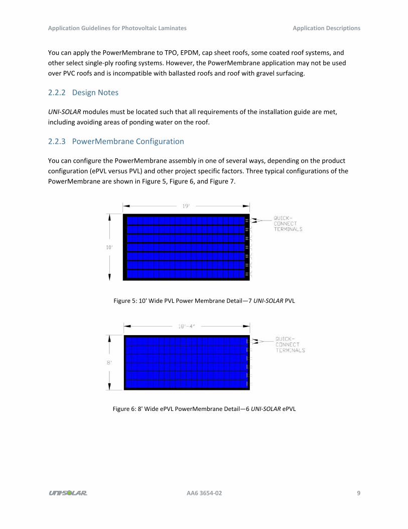
2.2.3 PowerMembrane Configuration
You can configure the PowerMembrane assembly in one of several ways, depending on the product
configuration (ePVL versus PVL) and other project specific factors. Three typical configurations of the
PowerMembrane are shown in Figure 5, Figure 6, and Figure 7.
Figure 5: 10' Wide PVL Power Membrane Detail—7 UNI‐SOLAR PVL
Figure 6: 8' Wide ePVL PowerMembrane Detail—6 UNI‐SOLAR ePVL
Application Guidelines for Photovoltaic Laminates Application Descriptions
AA6 3654‐02 10
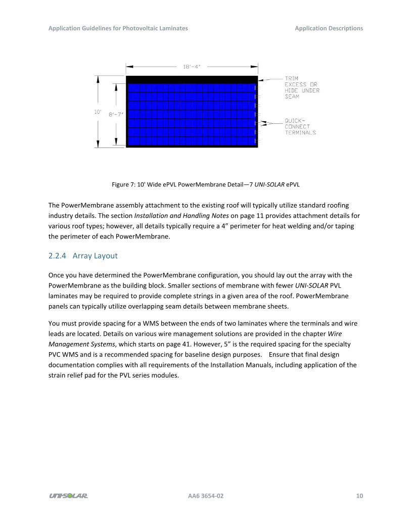
Figure 7: 10' Wide ePVL PowerMembrane Detail—7 UNI‐SOLAR ePVL
The PowerMembrane assembly attachment to the existing roof will typically utilize standard roofing
industry details. The section Installation and Handling Notes on page 11 provides attachment details for
various roof types; however, all details typically require a 4” perimeter for heat welding and/or taping
the perimeter of each PowerMembrane.
2.2.4 Array Layout
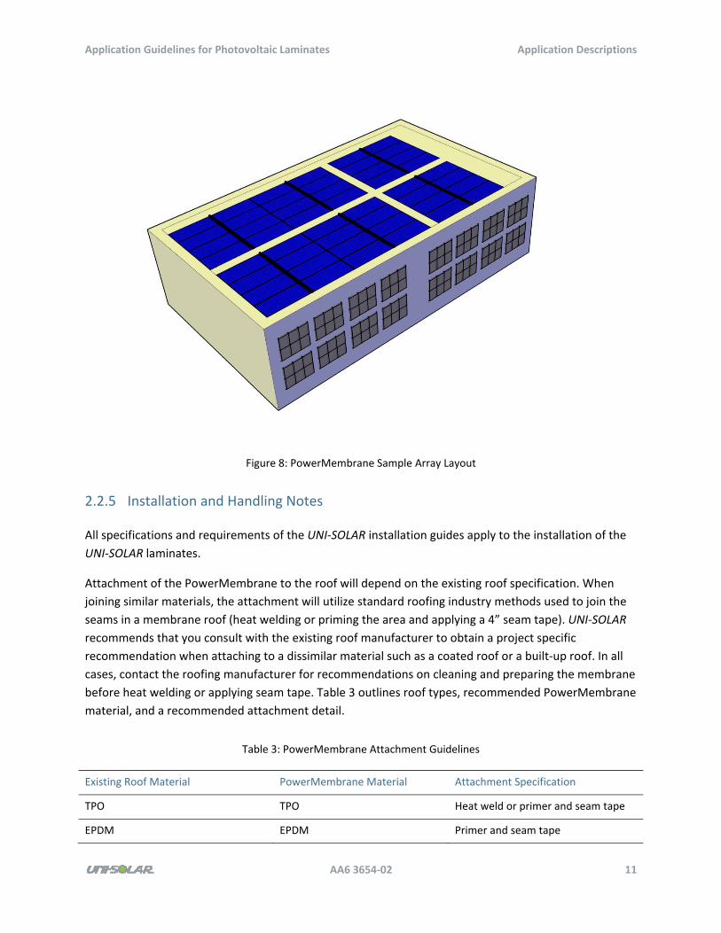
Once you have determined the PowerMembrane configuration, you should lay out the array with the
PowerMembrane as the building block. Smaller sections of membrane with fewer UNI‐SOLAR PVL
laminates may be required to provide complete strings in a given area of the roof. PowerMembrane
panels can typically utilize overlapping seam details between membrane sheets.
You must provide spacing for a WMS between the ends of two laminates where the terminals and wire
leads are located. Details on various wire management solutions are provided in the chapter Wire
Management Systems, which starts on page 41. However, 5” is the required spacing for the specialty
PVC WMS and is a recommended spacing for baseline design purposes. Ensure that final design
documentation complies with all requirements of the Installation Manuals, including application of the
strain relief pad for the PVL series modules.
Application Guidelines for Photovoltaic Laminates Application Descriptions
AA6 3654‐02 11
Figure 8: PowerMembrane Sample Array Layout
2.2.5 Installation and Handling Notes
All specifications and requirements of the UNI‐SOLAR installation guides apply to the installation of the
UNI‐SOLAR laminates.
Attachment of the PowerMembrane to the roof will depend on the existing roof specification. When
joining similar materials, the attachment will utilize standard roofing industry methods used to join the
seams in a membrane roof (heat welding or priming the area and applying a 4” seam tape). UNI‐SOLAR
recommends that you consult with the existing roof manufacturer to obtain a project specific
recommendation when attaching to a dissimilar material such as a coated roof or a built‐up roof. In all
cases, contact the roofing manufacturer for recommendations on cleaning and preparing the membrane
before heat welding or applying seam tape. Table 3 outlines roof types, recommended PowerMembrane
material, and a recommended attachment detail.
Table 3: PowerMembrane Attachment Guidelines
Existing Roof Material PowerMembrane Material Attachment Specification
TPO TPO Heat weld or primer and seam tape
EPDM EPDM Primer and seam tape

Application Guidelines for Photovoltaic Laminates Application Descriptions
AA6 3654‐02 12
Existing Roof Material PowerMembrane Material Attachment Specification
Built‐up TPO or EPDM Secondary adhesive primer and seam
tape
Coated Roof System TPO or EPDM Specialty primer, seam tape, and
perimeter coating detail
During installation, be sure to handle and transport the PowerMembrane appropriately. The
PowerMembrane should be stored flat and may be stacked as long as no scratching of the laminate or
damage to the terminals occurs.
Several methods are employed by Uni‐Solar partners to transport the PowerMembrane and lift to the
roof. One common method involves placing the PowerMembrane on a flat platform and lift to the roof
using a crane. For ease of shipping and lifting with a smaller platform, the PowerMembrane assembly
may be folded lengthwise between the laminates such that the roof membrane creases and the Uni‐
Solar laminates are not bent or creased.
Roll the PowerMembrane on a 20” rigid tube and lifting to the roof with a grade‐all has also been
employed, but care must be taken not to stress the terminals (especially on the PVL series)and to ensure
that the minimum radius of the laminate is not exceeded.
Once laminates are installed on the roof, minimize any foot traffic over the array. Do not place tools and
material handling equipment (roof carts) on, or allow them to run across, the array.
2.2.6 Labor Case Study
Table 4 shows averages for a PowerMembrane installation under good conditions with efficient labor
performance and is an example of a union roofing labor installation of an ~970 kW installation in North
America. Note that the time frames in the table do not include the production of the PowerMembrane
mats in a controlled warehouse‐like environment. These are strictly roofing installation guidelines only
and must not be used for all projects.
Table 4: PowerMembrane Installation Averages
kW/Day Crew
Total
Hours
kW per
man‐hour
kW per
man‐day
# PVL per
man‐hour
# PVL per
man day
Ramp‐up and overall
project 44.6 16.5 132 0.34 2.73 2.37 18.93
Refer to the appendixes for the PowerMembrane labor case study.

Application Guidelines for Photovoltaic Laminates Application Descriptions
AA6 3654‐02 13
2.2.7 Wind Resistance
The wind uplift rating of a PowerMembrane assembly to a roof is typically driven by the wind uplift
resistance of the roof system due to the low profile and high strength of the adhesive. Testing
conducted in accordance with FM Standard 4470 and Miami‐Dade TAS 114‐95 resulted in the failure of
the underlying roof system at over 270 psf. While the design pressure applied to a building cladding
component varies based on building height, geometry, and location on the roof, 270 psf is sufficient to
withstand Class III Hurricane winds of 130 MPH in most cases. Refer to Section 7 of this document for
information on certifications and approvals.
2.2.8 Reference Project Photo
Figure 9: Reference Project Photo for Bonding to Removable Single‐Ply Membranes
2.3 Direct Bond to Standing Seam Metal Roofs
The UNI‐SOLAR application direct bond to standing seam metal roofs consists of installing the UNI‐
SOLAR laminate directly to a metal roofing pan. Laminates are field‐applied to an approved roofing
panel in accordance with all specifications of the installation guide.
Applicable UNI‐SOLAR products include the PVL and ePVL series. UNI‐SOLAR does not supply a
completed PowerMembrane assembly.
2.3.1 Applicable Roof Types
You can apply the UNI‐SOLAR PVL product to standing seam roofing panels meeting the following
requirements:
Minimum 16” wide space between the seams
Application Guidelines for Photovoltaic Laminates Application Descriptions
AA6 3654‐02 14
Steel substrate material
Panel coating approved by UNI‐SOLAR
All requirements of the installation guide and Approved Substrates list.
2.3.2 Design Notes
UNI‐SOLAR modules must be located such that all requirements of the installation guide are met
including avoiding areas of ponding water on the roof and avoiding panel lap seams.
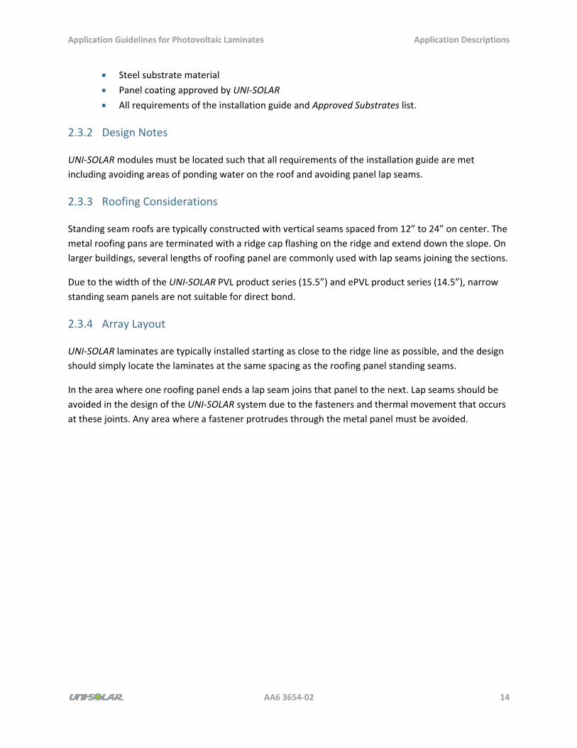
2.3.3 Roofing Considerations
Standing seam roofs are typically constructed with vertical seams spaced from 12” to 24” on center. The
metal roofing pans are terminated with a ridge cap flashing on the ridge and extend down the slope. On
larger buildings, several lengths of roofing panel are commonly used with lap seams joining the sections.
Due to the width of the UNI‐SOLAR PVL product series (15.5”) and ePVL product series (14.5”), narrow
standing seam panels are not suitable for direct bond.
2.3.4 Array Layout
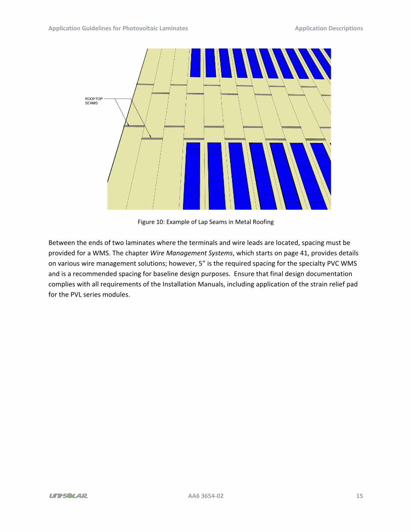
UNI‐SOLAR laminates are typically installed starting as close to the ridge line as possible, and the design
should simply locate the laminates at the same spacing as the roofing panel standing seams.
In the area where one roofing panel ends a lap seam joins that panel to the next. Lap seams should be
avoided in the design of the UNI‐SOLAR system due to the fasteners and thermal movement that occurs
at these joints. Any area where a fastener protrudes through the metal panel must be avoided.
Application Guidelines for Photovoltaic Laminates Application Descriptions
AA6 3654‐02 15
Figure 10: Example of Lap Seams in Metal Roofing
Between the ends of two laminates where the terminals and wire leads are located, spacing must be
provided for a WMS. The chapter Wire Management Systems, which starts on page 41, provides details
on various wire management solutions; however, 5” is the required spacing for the specialty PVC WMS
and is a recommended spacing for baseline design purposes. Ensure that final design documentation
complies with all requirements of the Installation Manuals, including application of the strain relief pad
for the PVL series modules.
Application Guidelines for Photovoltaic Laminates Application Descriptions
AA6 3654‐02 16
Figure 11: Direct Bond to Standing Seam Metal Roof Sample Array Layout
2.3.5 Installation and Handling Notes
All specifications and requirements of the UNI‐SOLAR installation guides apply to the installation of the
UNI‐SOLAR laminates.
Once laminates are installed on the roof, minimize any foot traffic over the array. Do not place tools and
material handling equipment (roof carts) on, or allow them to run across, the array.
2.3.6 Wind Resistance
The wind uplift rating of a UNI‐SOLAR laminate directly bonded to a roof is typically driven by the wind
uplift resistance of the roof system due to the low profile and high strength of the adhesive. Testing
conducted in accordance with FM Standard 4470 and Miami‐Dade TAS 114‐95 resulted in the failure of
the underlying roof system at over 270 psf. While the design pressure applied to a building cladding
component varies based on building height, geometry, and location on the roof, 270 psf is sufficient to
withstand Class III Hurricane winds of 130 MPH in most cases.
Application Guidelines for Photovoltaic Laminates Application Descriptions
AA6 3654‐02 17
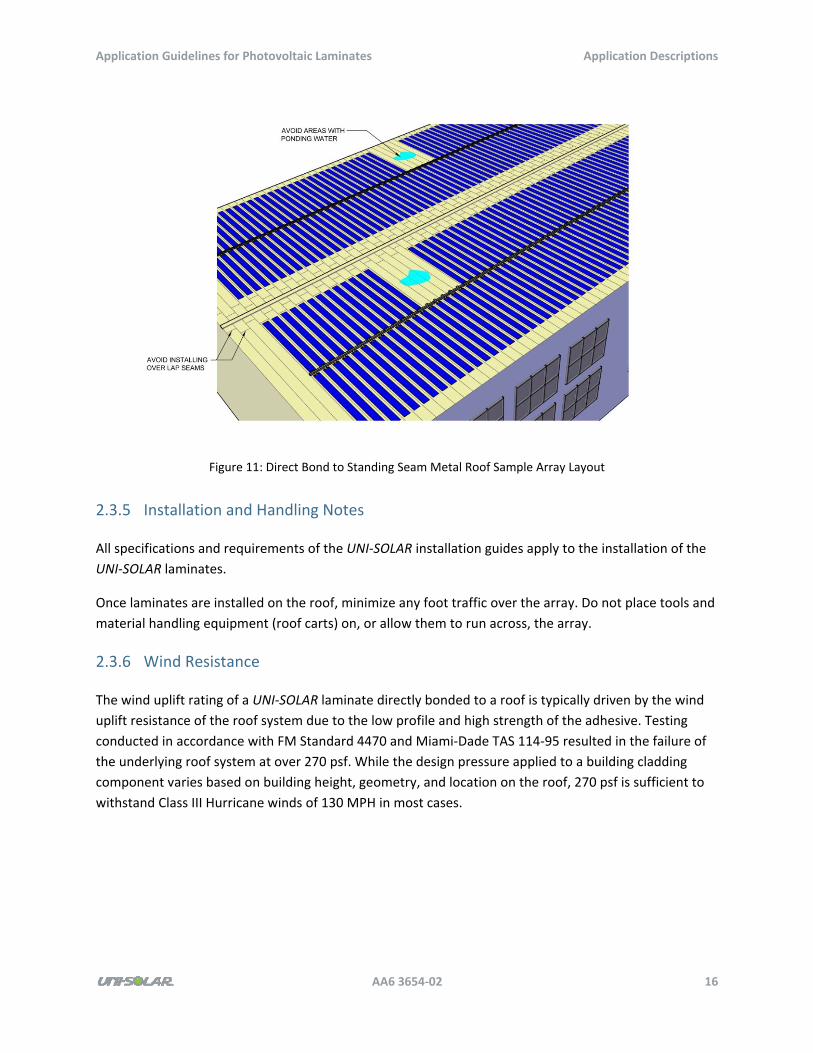
2.3.7 Reference Project Photo
Figure 12: Reference Project Photo for Direct Bond to Standing Seam Metal Roofs
2.4 Standing Seam Metal Roofs Not Suitable for Direct Bond
Some standing seam metal roofs are not suitable for direct bond. The UNI‐SOLAR application for
standing seam metal roofs not suitable for direct bond consists of installing the UNI‐SOLAR laminate to
a new metal roofing pan that is secured to the existing roof. Laminates are field or factory‐applied to an
approved roofing panel in accordance with all specifications of the installation guide.
An alternate solution for an unsuitable standing seam metal roof consists of overlaying the metal roof
with an insulation filler and new membrane roof. Refer to the previous sections regarding membrane
applications for installation to a new membrane roof.
Applicable UNI‐SOLAR products include the PVL and ePVL series.
2.4.1 Applicable Roof Types
Roof types suitable for this application are standing seam roofs with seams less than 16” on center, pans
with ribbed profiles, or widely spaced seams that excessively reduce power density.
Application Guidelines for Photovoltaic Laminates Application Descriptions
AA6 3654‐02 18
2.4.2 Design Notes
Panel Design
You should size new standing seam metal pans to minimize shading from the standing seams and
maximize power density on the roof. UNI‐SOLAR recommends a configuration with 16” wide panels and
1” vertical seams. A structural engineer must determine the details of material finish, gauge, and profile
based on the expected environmental loads and applicable building codes at the project site.
Panel Layout
The array design should position panels parallel to the roof slope at the panel width spacing. Standing
seam panels do not require additional space between panels for fastening.
You must provide spacing for a WMS between the ends of two laminates, where the terminals and wire
leads are located. Details on various wire management solutions are provided in the chapter Wire
Management Systems, which starts on page 41. However, 5” is the required spacing for the specialty
PVC WMS and is a recommended spacing for baseline design purposes. Ensure that final design
documentation complies with all requirements of the Installation Manuals, including application of the
strain relief pad for the PVL series modules.
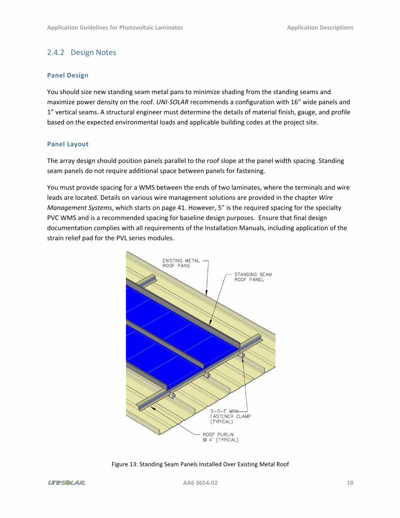
Figure 13: Standing Seam Panels Installed Over Existing Metal Roof
Application Guidelines for Photovoltaic Laminates Application Descriptions
AA6 3654‐02 19
Panel Attachment
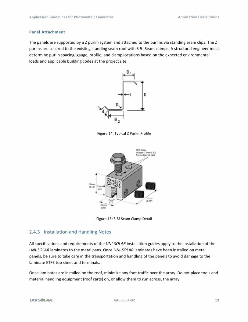
The panels are supported by a Z purlin system and attached to the purlins via standing seam clips. The Z
purlins are secured to the existing standing seam roof with S‐5! Seam clamps. A structural engineer must
determine purlin spacing, gauge, profile, and clamp locations based on the expected environmental
loads and applicable building codes at the project site.
Figure 14: Typical Z Purlin Profile
Figure 15: S‐5! Seam Clamp Detail
2.4.3 Installation and Handling Notes
All specifications and requirements of the UNI‐SOLAR installation guides apply to the installation of the
UNI‐SOLAR laminates to the metal pans. Once UNI‐SOLAR laminates have been installed on metal
panels, be sure to take care in the transportation and handling of the panels to avoid damage to the
laminate ETFE top sheet and terminals.
Once laminates are installed on the roof, minimize any foot traffic over the array. Do not place tools and
material handling equipment (roof carts) on, or allow them to run across, the array.
Application Guidelines for Photovoltaic Laminates Application Descriptions
AA6 3654‐02 20
2.4.4 Wind Resistance
The wind uplift rating of the new metal panel assembly will be determined by the project structural
engineer specifying the metal panels, purlins, and clamp details.
2.4.5 Reference Project Photo
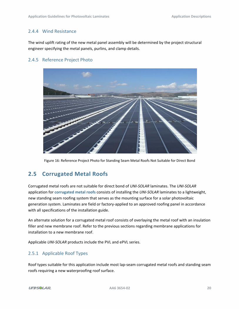
Figure 16: Reference Project Photo for Standing Seam Metal Roofs Not Suitable for Direct Bond
2.5 Corrugated Metal Roofs
Corrugated metal roofs are not suitable for direct bond of UNI‐SOLAR laminates. The UNI‐SOLAR
application for corrugated metal roofs consists of installing the UNI‐SOLAR laminates to a lightweight,
new standing seam roofing system that serves as the mounting surface for a solar photovoltaic
generation system. Laminates are field or factory‐applied to an approved roofing panel in accordance
with all specifications of the installation guide.
An alternate solution for a corrugated metal roof consists of overlaying the metal roof with an insulation
filler and new membrane roof. Refer to the previous sections regarding membrane applications for
installation to a new membrane roof.
Applicable UNI‐SOLAR products include the PVL and ePVL series.
2.5.1 Applicable Roof Types
Roof types suitable for this application include most lap‐seam corrugated metal roofs and standing seam
roofs requiring a new waterproofing roof surface.
Application Guidelines for Photovoltaic Laminates Application Descriptions
AA6 3654‐02 21
2.5.2 Design Notes
Panel Design
You should size new standing seam metal pans to minimize shading from the standing seams and
maximize power density on the roof. UNI‐SOLAR recommends a configuration with 16” wide panels and
1” vertical seams. A structural engineer must determine the details of material finish, gauge, and profile
based on the expected environmental loads and applicable building codes at the project site.
Panel Layout
This application provides a new standing seam metal roof over the existing roof deck. You must lay out
roofing panels to cover the entire roof surface targeted for UNI‐SOLAR installation from the ridge to the
eave. You should locate UNI‐SOLAR laminates in the most optimal areas of the new proposed standing
seam roof.
You must provide spacing for a WMS between the ends of two laminates, where the terminals and wire
leads are located. Details on various wire management solutions are provided in the chapter Wire
Management Systems, which starts on page 41. However, 5” is the required spacing for the specialty
PVC WMS and is a recommended spacing for baseline design purposes. Ensure that final design
documentation complies with all requirements of the Installation Manuals, including application of the
strain relief pad for the PVL series modules.
Panel Attachment
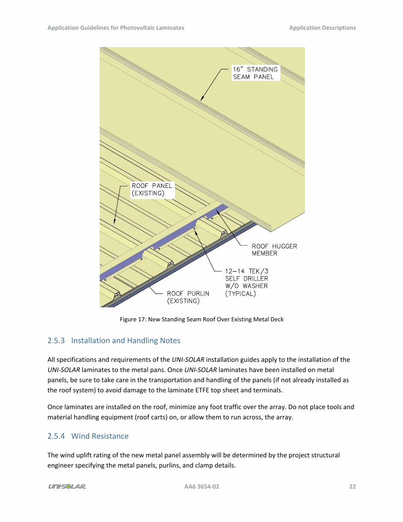
The standing seam panels are supported by a low‐profile structural purlin system. Roof Hugger® purlins
are fabricated to fit the existing roof profile and tie into the existing roof structure, in many cases adding
load bearing capacity to the roof. Standing seam panels are secured to the roof hugger purlins via
standing seam clips.
Application Guidelines for Photovoltaic Laminates Application Descriptions
AA6 3654‐02 22
Figure 17: New Standing Seam Roof Over Existing Metal Deck
2.5.3 Installation and Handling Notes
All specifications and requirements of the UNI‐SOLAR installation guides apply to the installation of the
UNI‐SOLAR laminates to the metal pans. Once UNI‐SOLAR laminates have been installed on metal
panels, be sure to take care in the transportation and handling of the panels (if not already installed as
the roof system) to avoid damage to the laminate ETFE top sheet and terminals.
Once laminates are installed on the roof, minimize any foot traffic over the array. Do not place tools and
material handling equipment (roof carts) on, or allow them to run across, the array.
2.5.4 Wind Resistance
The wind uplift rating of the new metal panel assembly will be determined by the project structural
engineer specifying the metal panels, purlins, and clamp details.
Application Guidelines for Photovoltaic Laminates Application Descriptions
AA6 3654‐02 23
2.5.5 Reference Project Photo
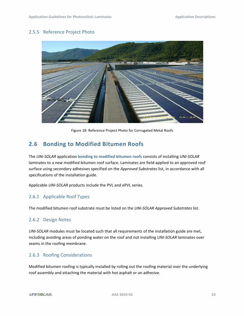
Figure 18: Reference Project Photo for Corrugated Metal Roofs
2.6 Bonding to Modified Bitumen Roofs
The UNI‐SOLAR application bonding to modified bitumen roofs consists of installing UNI‐SOLAR
laminates to a new modified bitumen roof surface. Laminates are field‐applied to an approved roof
surface using secondary adhesives specified on the Approved Substrates list, in accordance with all
specifications of the installation guide.
Applicable UNI‐SOLAR products include the PVL and ePVL series.
2.6.1 Applicable Roof Types
The modified bitumen roof substrate must be listed on the UNI‐SOLAR Approved Substrates list.
2.6.2 Design Notes
UNI‐SOLAR modules must be located such that all requirements of the installation guide are met,
including avoiding areas of ponding water on the roof and not installing UNI‐SOLAR laminates over
seams in the roofing membrane.
2.6.3 Roofing Considerations
Modified bitumen roofing is typically installed by rolling out the roofing material over the underlying
roof assembly and attaching the material with hot asphalt or an adhesive.
Application Guidelines for Photovoltaic Laminates Application Descriptions
AA6 3654‐02 24
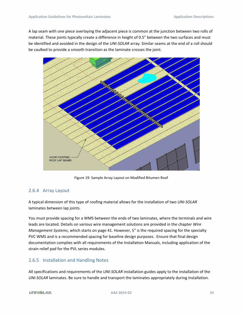
A lap seam with one piece overlaying the adjacent piece is common at the junction between two rolls of
material. These joints typically create a difference in height of 0.5” between the two surfaces and must
be identified and avoided in the design of the UNI‐SOLAR array. Similar seams at the end of a roll should
be caulked to provide a smooth transition as the laminate crosses the joint.
Figure 19: Sample Array Layout on Modified Bitumen Roof
2.6.4 Array Layout
A typical dimension of this type of roofing material allows for the installation of two UNI‐SOLAR
laminates between lap joints.
You must provide spacing for a WMS between the ends of two laminates, where the terminals and wire
leads are located. Details on various wire management solutions are provided in the chapter Wire
Management Systems, which starts on page 41. However, 5” is the required spacing for the specialty
PVC WMS and is a recommended spacing for baseline design purposes. Ensure that final design
documentation complies with all requirements of the Installation Manuals, including application of the
strain relief pad for the PVL series modules.
2.6.5 Installation and Handling Notes
All specifications and requirements of the UNI‐SOLAR installation guides apply to the installation of the
UNI‐SOLAR laminates. Be sure to handle and transport the laminates appropriately during installation.
Application Guidelines for Photovoltaic Laminates Application Descriptions
AA6 3654‐02 25
Once laminates are installed on the roof, minimize any foot traffic over the array. Do not place tools and
material handling equipment (roof carts) on, or allow them to run across, the array.
2.6.6 Reference Project Photo
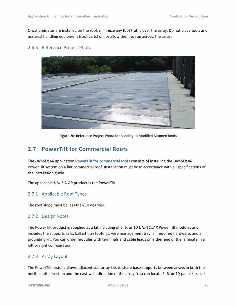
Figure 20: Reference Project Photo for Bonding to Modified Bitumen Roofs
2.7 PowerTilt for Commercial Roofs
The UNI‐SOLAR application PowerTilt for commercial roofs consists of installing the UNI‐SOLAR
PowerTilt system on a flat commercial roof. Installation must be in accordance with all specifications of
the installation guide.
The applicable UNI‐SOLAR product is the PowerTilt.
2.7.1 Applicable Roof Types
The roof slope must be less than 10 degrees.
2.7.2 Design Notes
The PowerTilt product is supplied as a kit including of 5, 6, or 10 UNI‐SOLAR PowerTilt modules and
includes the supports rails, ballast tray footings, wire management tray, all required hardware, and a
grounding kit. You can order modules with terminals and cable leads on either end of the laminate in a
left or right configuration.
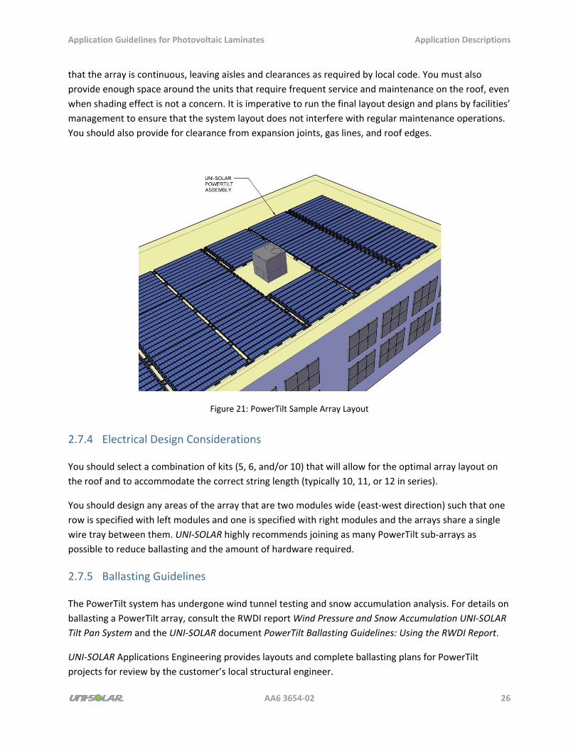
2.7.3 Array Layout
The PowerTilt system allows adjacent sub‐array kits to share base supports between arrays in both the
north‐south direction and the east‐west direction of the array. You can locate 5, 6, or 10‐panel kits such
Application Guidelines for Photovoltaic Laminates Application Descriptions
AA6 3654‐02 26
that the array is continuous, leaving aisles and clearances as required by local code. You must also
provide enough space around the units that require frequent service and maintenance on the roof, even
when shading effect is not a concern. It is imperative to run the final layout design and plans by facilities’
management to ensure that the system layout does not interfere with regular maintenance operations.
You should also provide for clearance from expansion joints, gas lines, and roof edges.
Figure 21: PowerTilt Sample Array Layout
2.7.4 Electrical Design Considerations
You should select a combination of kits (5, 6, and/or 10) that will allow for the optimal array layout on
the roof and to accommodate the correct string length (typically 10, 11, or 12 in series).
You should design any areas of the array that are two modules wide (east‐west direction) such that one
row is specified with left modules and one is specified with right modules and the arrays share a single
wire tray between them. UNI‐SOLAR highly recommends joining as many PowerTilt sub‐arrays as
possible to reduce ballasting and the amount of hardware required.
2.7.5 Ballasting Guidelines
The PowerTilt system has undergone wind tunnel testing and snow accumulation analysis. For details on
ballasting a PowerTilt array, consult the RWDI report Wind Pressure and Snow Accumulation UNI‐SOLAR
Tilt Pan System and the UNI‐SOLAR document PowerTilt Ballasting Guidelines: Using the RWDI Report.
UNI‐SOLAR Applications Engineering provides layouts and complete ballasting plans for PowerTilt
projects for review by the customer’s local structural engineer.
Application Guidelines for Photovoltaic Laminates Application Descriptions
AA6 3654‐02 27
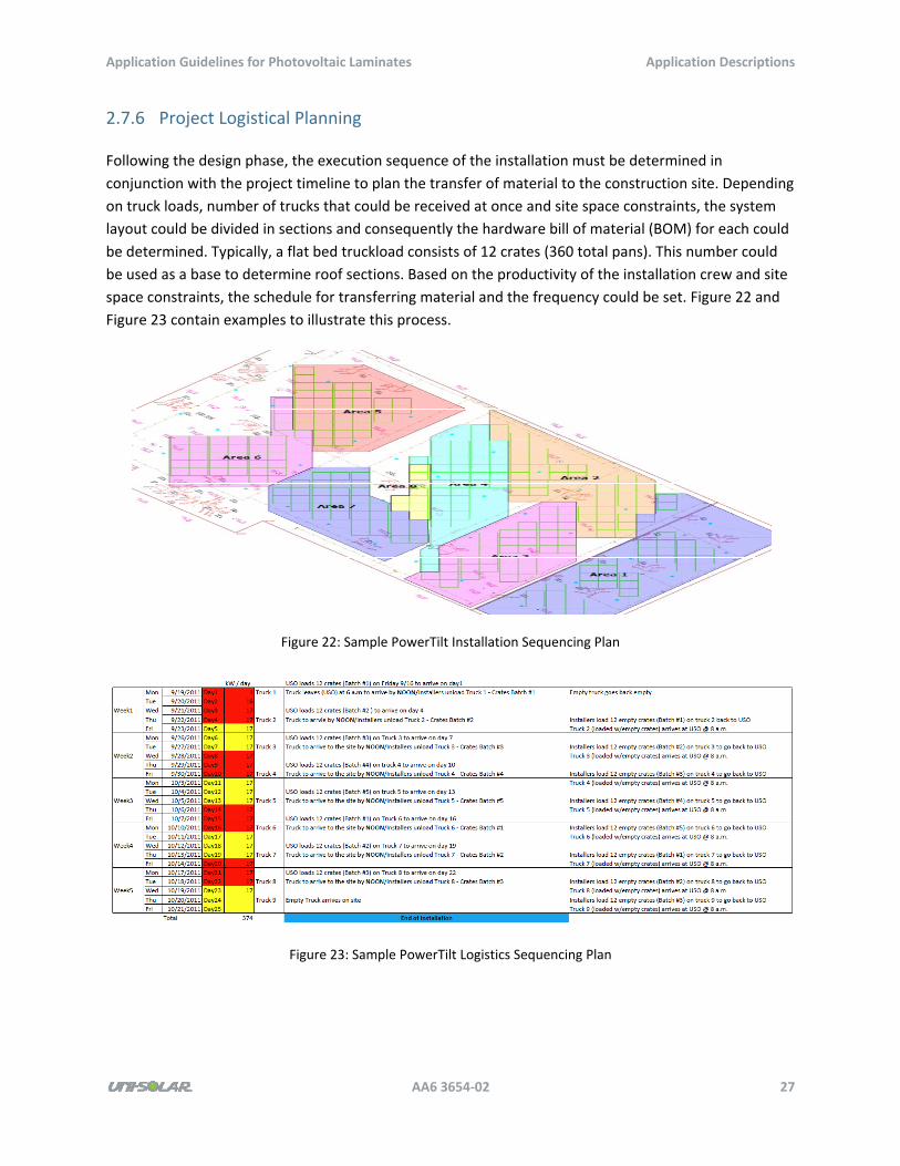
2.7.6 Project Logistical Planning
Following the design phase, the execution sequence of the installation must be determined in
conjunction with the project timeline to plan the transfer of material to the construction site. Depending
on truck loads, number of trucks that could be received at once and site space constraints, the system
layout could be divided in sections and consequently the hardware bill of material (BOM) for each could
be determined. Typically, a flat bed truckload consists of 12 crates (360 total pans). This number could
be used as a base to determine roof sections. Based on the productivity of the installation crew and site
space constraints, the schedule for transferring material and the frequency could be set. Figure 22 and
Figure 23 contain examples to illustrate this process.
Figure 22: Sample PowerTilt Installation Sequencing Plan
Figure 23: Sample PowerTilt Logistics Sequencing Plan
Application Guidelines for Photovoltaic Laminates Application Descriptions
AA6 3654‐02 28
2.7.7 Installation and Handling Notes
All specifications and requirements of the UNI‐SOLAR installation guides apply to the installation of the
UNI‐SOLAR PowerTilt system. Be sure to handle and transport the PowerTilt modules appropriately
during installation.
Laminates of the PowerTilt system are factory‐applied to the pans and loaded to wooden crates that can
hold 30 pans in each. Once unloaded off the truck, loaded crates can be taken up to the roof installation
areas with equipment that can handle the weight in an effort to minimize handling of pans on the
ground, and to increase productivity and efficiency. However, fully loaded crates weigh more than 1200
pounds. UNI‐SOLAR highly recommends, based on the roof condition, not to lay the crate down on the
roof surface, and to make sure that the crate stays above the roof surface. All roof loading of panels
must be approved by a professional structural engineer.
2.7.8 Labor Case Study
The following productivity data is based on a rooftop non‐union labor of a ~440 kW DC with (3,040) UNI‐
SOLAR PT‐144 PV modules in North America. Installation training was provided to the installer’s
superintendent before the project began, but the installation crews had no prior training or experience
with the PowerTilt system. On‐site personnel completed daily reports that detail the crew size, work
completed, weather, and other data about the conditions on site. The crew size, hours worked, and
number of PowerTilt pans installed in a day are important metrics that were captured and are used in
this analysis to determine the PV capacity (kW) installed per labor hour.
The scope of work of this labor study is strictly for the mechanical installation of the PowerTilt system.
Specific activities of this scope include:
Unloading flatbeds
Shipping PowerTilt crates to the jobsite (assumes no onsite storage)
Transporting material to the roof (assumes adequate access and staging for the crane and
materials)
Layout and locating the array
Assembly of the PowerTilt ballasted framing system
Ballasting the array with paver blocks
Installation of integrated wire trays
Installation of the PowerTilt pans
Ground testing
Activities not included in this scope include:
Interconnection of the PowerTilt module leads
Wiring from the panels to combiner boxes
Combiner box installation
Application Guidelines for Photovoltaic Laminates Application Descriptions
AA6 3654‐02 29
Inverter installation
Any other electrical, site work, or structural work
In this case study, weather (including rain and high winds) was an important factor during construction.
When safe, the crews performed work through rain and wind; however, when the crew did not work
due to weather, only the hours worked were included in the total hours for the day. This guide is based
on a sample project that was installed from April to June in North America. Productivity may be
adversely affected during winter months and should be taken into consideration.
This crew is based on an eight‐man crew that had never installed the PowerTilt system. As a result, there
was a learning curve to overcome in the beginning of the installation. Once the crew became familiar
with the PowerTilt system, the installation rate increased. Installation hours provided below are
inclusive of all phases of the installation including ramp‐up. The labor hours presented below are
inclusive of reasonable minor array relocation work due to misinterpretation of drawings. Significant
array relocation labor and the associated structural evaluation are not within the scope of this case
study, but the developer should be aware of the structural engineering evaluation required to design
any ballasted PV array or modify the array design in the field. Productivity data was as follows:
Total labor hours: 2126
Total installed kW: 437.76
kW per labor hour: 0.206
This data will be different in the case of removing a section or several sections of the array. Activities
such as disconnecting the fuses and strings, removing cables and conduit for the sections to be
disassembled have to be planned. Based on the roof space and the distances to be traveled in order to
stage the disconnected sub‐arrays material, the productivity data above is expected to change and
improve since activities such as loading/unloading trucks, transferring material to the roof and to the
installation areas are unlikely to be required again. However, times that will be shown in these cases will
have to be doubled since the same amount of time to disassemble the sub‐array will be required to
assemble it again. Based on time studies conducted during installation trials strictly for mechanically
assembling the frame of a 10 PT‐144 sub‐array system, productivity data was as follows:
Total labor hours: 3.2
Total installed kW: 1.440
kW per labor hour: 0.450
Another installation trail was conducted for assembling a 40 PT‐144 system on a ballasted roof. The
productivity data collected includes the assembly times of the frames, the labor time that was required
for transferring material from the edge (the off loading area) of the roof to the installation area, and the
time that was required to markup the roof and ballast the system. Productivity data for that activity was
as follows:
Total labor hours: 19.20
Total installed kW: 5.760
Application Guidelines for Photovoltaic Laminates Application Descriptions
AA6 3654‐02 30
kW per labor hour: 0.300
It is important to point out that the above data will vary from one construction site to another based on
weather, storage and staging areas allocated, the size of the roof and the installation area, and roof
loading accessibility and feasibility. Moreover, the data will also depend on the productivity of the
installation crews, compliance with the certification processes, familiarity with the installation of the
product, and the accuracy and the clarity of the design drawings.
Refer to the appendixes for the PowerTilt labor case study.
2.7.9 Wind Resistance
The PowerTilt system can be engineered for wind speeds up to 125 mph. Refer to PowerTilt Array
Ballast Guidelines for additional details on determining the required ballast for a PowerTilt array. A
locally licensed structural engineer should review and approve any ballast calculations.
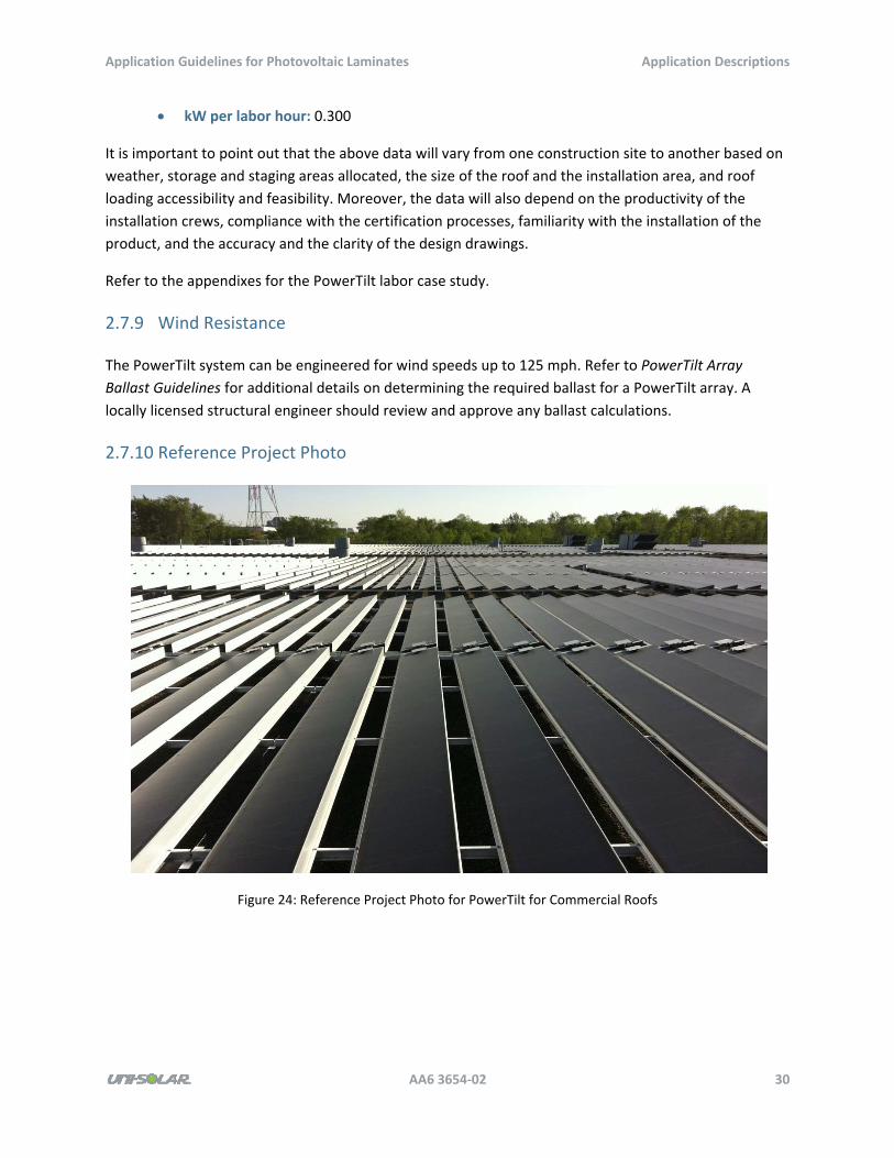
2.7.10 Reference Project Photo
Figure 24: Reference Project Photo for PowerTilt for Commercial Roofs
Application Guidelines for Photovoltaic Laminates Rooftop Array Design Considerations
AA6 3654‐02 31
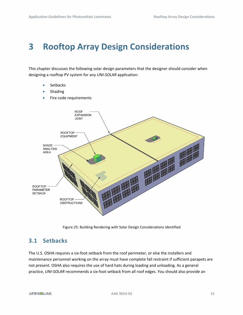
3 Rooftop Array Design Considerations
This chapter discusses the following solar design parameters that the designer should consider when
designing a rooftop PV system for any UNI‐SOLAR application:
Setbacks
Shading
Fire code requirements
Figure 25: Building Rendering with Solar Design Considerations Identified
3.1 Setbacks
The U.S. OSHA requires a six‐foot setback from the roof perimeter, or else the installers and
maintenance personnel working on the array must have complete fall restraint if sufficient parapets are
not present. OSHA also requires the use of hard hats during loading and unloading. As a general
practice, UNI‐SOLAR recommends a six‐foot setback from all roof edges. You should also provide an
Application Guidelines for Photovoltaic Laminates Rooftop Array Design Considerations
AA6 3654‐02 32
additional setback for mechanical equipment requiring service. UNI‐SOLAR recommends a four‐foot
setback for mechanical equipment.
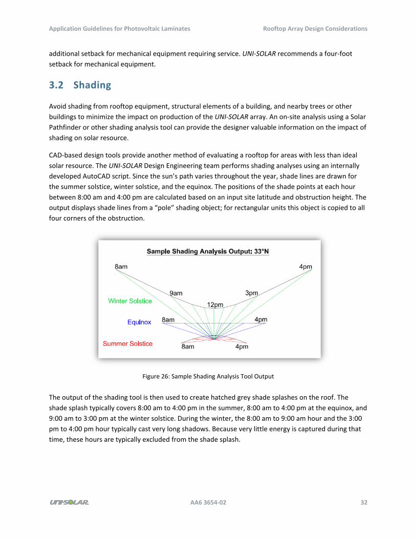
3.2 Shading
Avoid shading from rooftop equipment, structural elements of a building, and nearby trees or other
buildings to minimize the impact on production of the UNI‐SOLAR array. An on‐site analysis using a Solar
Pathfinder or other shading analysis tool can provide the designer valuable information on the impact of
shading on solar resource.
CAD‐based design tools provide another method of evaluating a rooftop for areas with less than ideal
solar resource. The UNI‐SOLAR Design Engineering team performs shading analyses using an internally
developed AutoCAD script. Since the sun’s path varies throughout the year, shade lines are drawn for
the summer solstice, winter solstice, and the equinox. The positions of the shade points at each hour
between 8:00 am and 4:00 pm are calculated based on an input site latitude and obstruction height. The
output displays shade lines from a “pole” shading object; for rectangular units this object is copied to all
four corners of the obstruction.
Figure 26: Sample Shading Analysis Tool Output
The output of the shading tool is then used to create hatched grey shade splashes on the roof. The
shade splash typically covers 8:00 am to 4:00 pm in the summer, 8:00 am to 4:00 pm at the equinox, and
9:00 am to 3:00 pm at the winter solstice. During the winter, the 8:00 am to 9:00 am hour and the 3:00
pm to 4:00 pm hour typically cast very long shadows. Because very little energy is captured during that
time, these hours are typically excluded from the shade splash.
Application Guidelines for Photovoltaic Laminates Rooftop Array Design Considerations
AA6 3654‐02 33
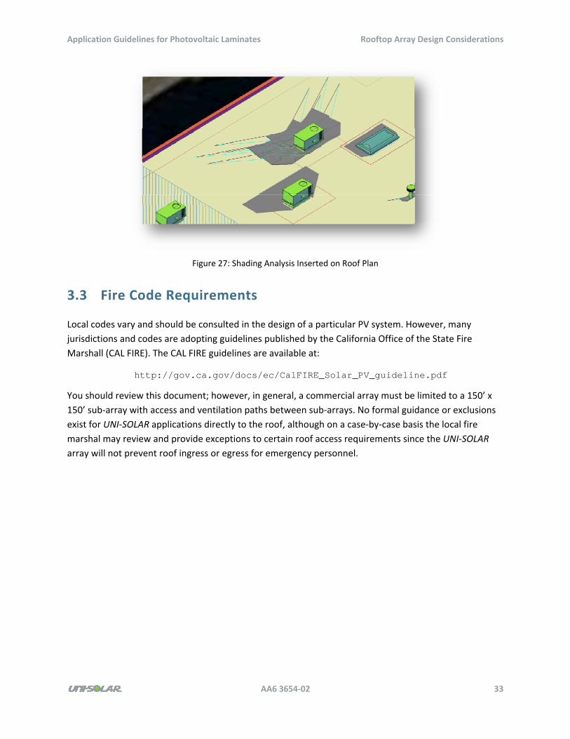
Figure 27: Shading Analysis Inserted on Roof Plan
3.3 Fire Code Requirements
Local codes vary and should be consulted in the design of a particular PV system. However, many
jurisdictions and codes are adopting guidelines published by the California Office of the State Fire
Marshall (CAL FIRE). The CAL FIRE guidelines are available at:
http://gov.ca.gov/docs/ec/CalFIRE_Solar_PV_guideline.pdf
You should review this document; however, in general, a commercial array must be limited to a 150’ x
150’ sub‐array with access and ventilation paths between sub‐arrays. No formal guidance or exclusions
exist for UNI‐SOLAR applications directly to the roof, although on a case‐by‐case basis the local fire
marshal may review and provide exceptions to certain roof access requirements since the UNI‐SOLAR
array will not prevent roof ingress or egress for emergency personnel.
Application Guidelines for Photovoltaic Laminates Energy Modeling
AA6 3654‐02 34
4 Energy Modeling
This chapter discusses the following factors for energy modeling:
Energy yield
Performance modeling
PV modeling software
PVSyst (software) modeling guidelines
4.1 Energy Yield
Comparative test sites and performance history of UNI‐SOLAR PV laminates have a significant history of
high energy yields. Numerous third‐party test sites have reported excellent kWh/kW yields throughout
the world. The UNI‐SOLAR publication Comprehensive Overview of Technical Information and Product
Performance Data contains many project references and third‐party test sites.
4.2 Performance Modeling
Energy modeling, or forecasting when and how much energy will be delivered by a PV system, is critical
to in the development and structuring of any PV project. Because of the differences between UNI‐SOLAR
amorphous silicon technology and crystalline PV, UNI‐SOLAR makes particular recommendations about
how to model energy performance.
4.3 PV Modeling Software
A number of publicly and commercially available energy‐modeling software platforms are available,
some better suited to modeling UNI‐SOLAR performance than others. Performance modeling tools can
be divided onto two categories: those that model performance on an hourly basis throughout a year of
typical environmental data and consider the characteristics of the particular system being analyzed and
those that do not. Since UNI‐SOLAR laminate temperature dependence and spectral sensitivity differ
from the characteristics of crystalline PV panels, UNI‐SOLAR recommends that the modeling tool you use
accounts for those factors. UNI‐SOLAR does not recommend PVWATTS or RET Screen since those tools
do not consider A‐Si temperature dependence and spectral sensitivity.
UNI‐SOLAR recommends PVSyst, a modeling software package based on research conducted by the
University of Geneva, as a preferred platform for modeling UNI‐SOLAR PV systems for three reasons:
Application Guidelines for Photovoltaic Laminates Energy Modeling
AA6 3654‐02 35
UNI‐SOLAR laminates were studied and the software adjusts for the spectral sensitivity of A‐
Si.
The software can use environmental data from the best available sources.
The software is known throughout the industry and recognized as a bankable performance
modeling package.
PVSyst steps through 8,760 hourly data points and at each hour uses the input environmental data to
calculate effective energy at the PV array based on direct irradiance, diffuse irradiance, ambient
temperature, and wind speed. That array energy is then derated for system losses, including inverter
efficiency curves. The output is an hourly file and summary report for a typical year based on the input
environmental data.
4.4 PVSyst Modeling Guidelines
This section provides standardized PVSyst input guidelines for modeling UNI‐SOLAR PVL laminates.
4.4.1 Meteorological Data
Meteorological data for PVSyst comes from National Renewable Energy Laboratory (NREL) as well as
several other data sources.
National Renewable Energy Laboratory (NREL)
PVSyst comes with synthetic weather data from many locations but also allows you to provide weather
data from an outside source. An ideal choice is Typical Meteorological Year (TMY) data from NREL, which
is now in its third revision (TMY3). TMY3 data represents an average year of solar irradiance (both global
and diffuse), ambient temperature, wind speed, and many other parameters in over 1,000 locations
across the United States. NREL compiled these sets of data from hourly data taken between 1991 and
2005 in the National Solar Radiation Database (NSRDB), and it can be accessed at:
http://rredc.nrel.gov/solar/old_data/nsrdb/1991-2005/tmy3/by_state_and_city.html
Other Data Sources
RetScreen, NASA, Meteonorm, and other meteo data providers can be used as data sources for PVSyst
simulation. The most accurate data sources will be ground‐based measurements located close to the
project site. Monthly averages of daily insolation are the least accurate type of meteo input.
4.4.2 Orientation
PVSyst includes orientation settings, where you can set parameters for BIPV and metal roof installations
as well as for PowerTilt.
Application Guidelines for Photovoltaic Laminates Energy Modeling
AA6 3654‐02 36
BIPV and Metal Roof Installations
When the UNI‐SOLAR laminates will be applied directly to a metal or membrane roof, use the Fixed
Tilted Plane field type in the Orientation parameter, and enter the plane tilt and azimuth of the array.
For a “flat roof” BIPV installation, the roof is not perfectly flat due to drainage; however, you can assume
an average 0 degree slope for simulation purposes. For a sloped roof installation, enter the roof slope
and azimuth. PVSyst allows for two different tilt and azimuth entries. Use the Double Orientation field
type if you have two different slopes on a roof and the array will be tied to a single inverter.
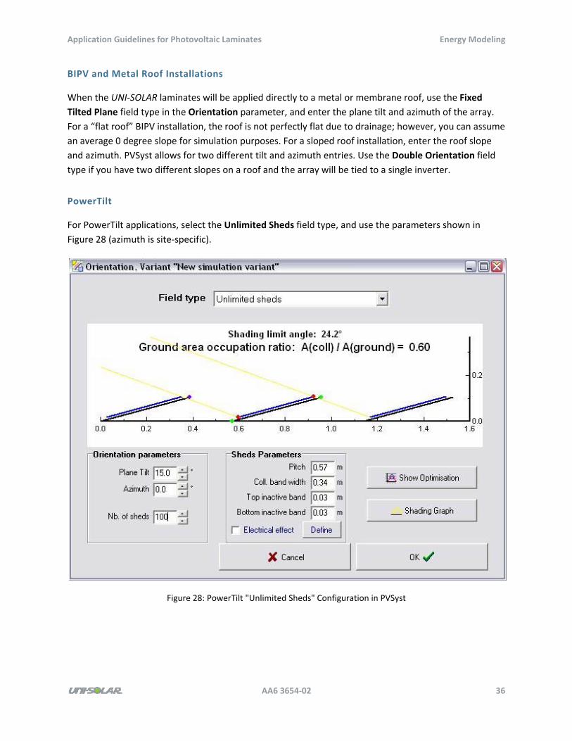
PowerTilt
For PowerTilt applications, select the Unlimited Sheds field type, and use the parameters shown in
Figure 28 (azimuth is site‐specific).
Figure 28: PowerTilt "Unlimited Sheds" Configuration in PVSyst
Application Guidelines for Photovoltaic Laminates Energy Modeling
AA6 3654‐02 37
4.4.3 Model Parameters
PVSyst allows for customization of its loss parameters. You can access this feature by clicking the
Detailed Losses button when configuring the inverter and modules in the System page.
4.4.4 Thermal Loss Factor
Thermal loss strongly influences the outcome of the simulation. The array’s thermal behavior depends
on changes in ambient temperature and how the cell temperature responds. The thermal loss factor k characterizes this loss and is determined by observing panel temperature under standardized
conditions. This parameter is referred to as the normal operating cell temperature (NOCT). The
conditions are 800 W/m2 of solar irradiance and an ambient temperature of 20° C (68° F).
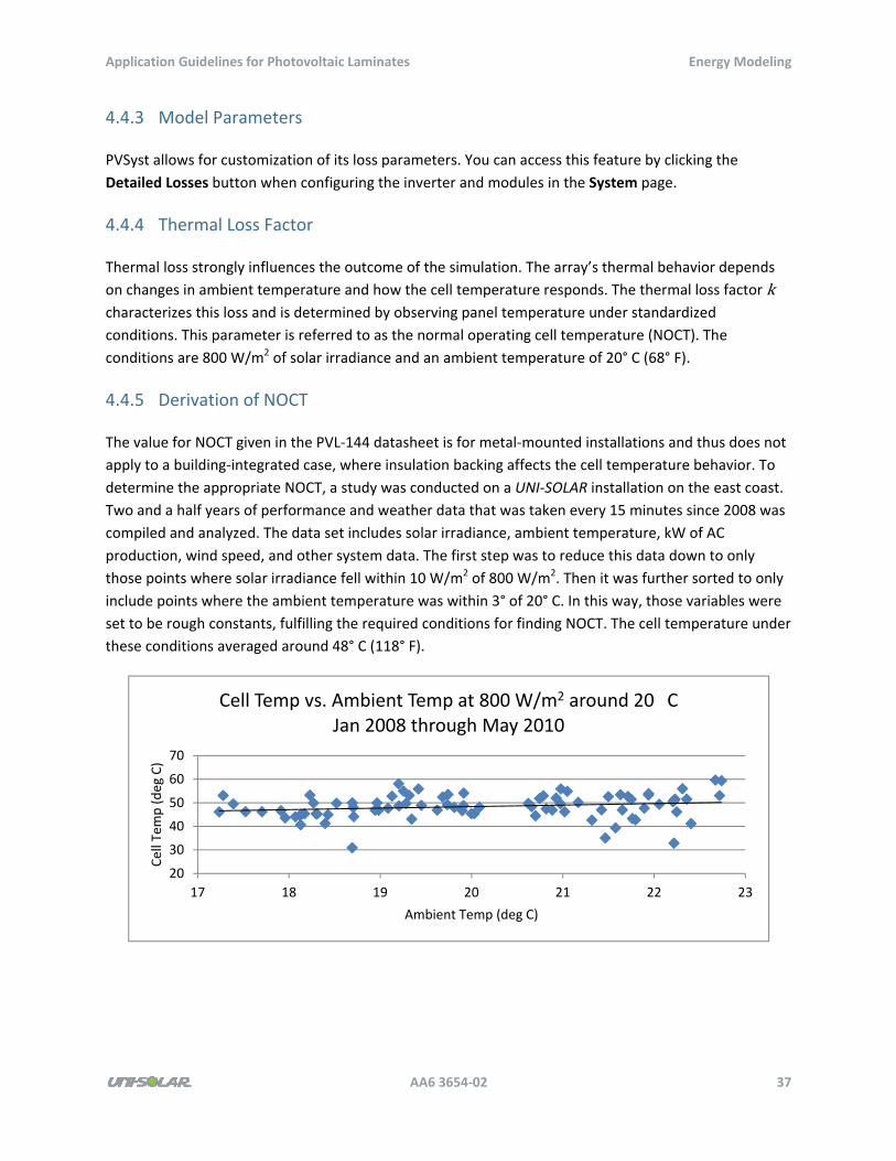
4.4.5 Derivation of NOCT
The value for NOCT given in the PVL‐144 datasheet is for metal‐mounted installations and thus does not
apply to a building‐integrated case, where insulation backing affects the cell temperature behavior. To
determine the appropriate NOCT, a study was conducted on a UNI‐SOLAR installation on the east coast.
Two and a half years of performance and weather data that was taken every 15 minutes since 2008 was
compiled and analyzed. The data set includes solar irradiance, ambient temperature, kW of AC
production, wind speed, and other system data. The first step was to reduce this data down to only
those points where solar irradiance fell within 10 W/m2 of 800 W/m2. Then it was further sorted to only
include points where the ambient temperature was within 3° of 20° C. In this way, those variables were
set to be rough constants, fulfilling the required conditions for finding NOCT. The cell temperature under
these conditions averaged around 48° C (118° F).
20
30
40
50
60
70
17 18 19 20 21 22 23
Cell Tem
p (deg C)
Ambient Temp (deg C)
Cell Temp vs. Ambient Temp at 800 W/m2 around 20 CJan 2008 through May 2010
Application Guidelines for Photovoltaic Laminates Energy Modeling
AA6 3654‐02 38
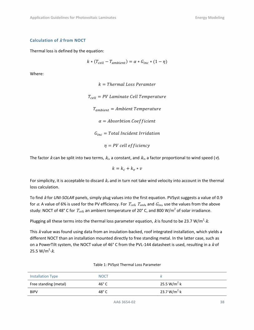
Calculation of k from NOCT
Thermal loss is defined by the equation:
1
Where:
The factor k can be split into two terms, kc, a constant, and kv, a factor proportional to wind speed (v).
For simplicity, it is acceptable to discard kv and in turn not take wind velocity into account in the thermal
loss calculation.
To find k for UNI‐SOLAR panels, simply plug values into the first equation. PVSyst suggests a value of 0.9
for α. A value of 6% is used for the PV efficiency. For Tcell, Tamb, and Ginc, use the values from the above
study: NOCT of 48° C for Tcell, an ambient temperature of 20° C, and 800 W/m2 of solar irradiance.
Plugging all these terms into the thermal loss parameter equation, k is found to be 23.7 W/m2∙k.
This k value was found using data from an insulation‐backed, roof integrated installation, which yields a
different NOCT than an installation mounted directly to free standing metal. In the latter case, such as
on a PowerTilt system, the NOCT value of 46° C from the PVL‐144 datasheet is used, resulting in a k of 25.5 W/m2∙k.
Table 1: PVSyst Thermal Loss Parameter
Installation Type NOCT k
Free standing (metal) 46° C 25.5 W/m2∙k
BIPV 48° C 23.7 W/m2∙k
Application Guidelines for Photovoltaic Laminates Energy Modeling
AA6 3654‐02 39
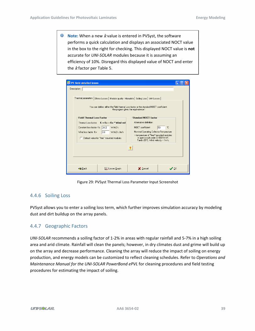
Note: When a new k value is entered in PVSyst, the software performs a quick calculation and displays an associated NOCT value
in the box to the right for checking. This displayed NOCT value is not
accurate for UNI‐SOLAR modules because it is assuming an
efficiency of 10%. Disregard this displayed value of NOCT and enter
the k factor per Table 5.
Figure 29: PVSyst Thermal Loss Parameter Input Screenshot
4.4.6 Soiling Loss
PVSyst allows you to enter a soiling loss term, which further improves simulation accuracy by modeling
dust and dirt buildup on the array panels.
4.4.7 Geographic Factors
UNI‐SOLAR recommends a soiling factor of 1‐2% in areas with regular rainfall and 5‐7% in a high soiling
area and arid climate. Rainfall will clean the panels; however, in dry climates dust and grime will build up
on the array and decrease performance. Cleaning the array will reduce the impact of soiling on energy
production, and energy models can be customized to reflect cleaning schedules. Refer to Operations and
Maintenance Manual for the UNI‐SOLAR PowerBond ePVL for cleaning procedures and field testing
procedures for estimating the impact of soiling.
Application Guidelines for Photovoltaic Laminates Energy Modeling
AA6 3654‐02 40
4.4.8 Snowfall Losses
When covered by snow, a solar PV system produces little or no energy. Solar photovoltaic energy yield
modeling packages do not account for the impact of snowfall on the system output, and a post‐
simulation correction must be made to account for the impact of snow on annual production. UNI‐
SOLAR conducted research and analysis on sites in snowfall areas and documented the results in Impact
of Snowfall on UNI‐SOLAR PV System Yield. The research results in loss factors (a percentage drop in
Normalized Performance Index), which is applied to the monthly energy production values from PVSyst.
Two sets of loss recommendations are presented for sites with flat roof installations and sites with
sloped installations of 15 degrees or more.
Table 6: Snowfall Losses for Flat Roof UNI‐SOLAR Installations
Inches of Snow Drop in NPI
0‐5" 10%
5‐10" 20%
10‐15" 30%
>15" 40%
Table 7: Snowfall Losses for Sloped UNI‐SOLAR Installations ≥ 15°
Inches of Snow Drop in NPI
0‐5" 5%
5‐10" 10%
10‐15" 20%
>15" 30%
4.4.9 Model Outputs
Sample PVSyst reports and snowfall correction reports are included in the appendixes.
Application Guidelines for Photovoltaic Laminates Wire Management Systems
AA6 3654‐02 41
5 Wire Management Systems
UNI‐SOLAR laminates require a wire management system (WMS) to manage the cable leads between
modules and the cable runs back to rooftop combiner boxes or inverters. Several options for wire
management are available that you can evaluate for cost, appearance, wind resistance, and snow
loading.
Balance of system requirements are different for the UNI‐SOLAR PVL and ePVL product lines. The PVL
products require a secondary strain relief and a cover for the terminals to avoid direct prolonged UV
exposure. Those requirements do not apply to the ePVL products. Consult the installation guides for
complete installation specifications.
5.1 PVC WMS
UNI‐SOLAR developed the PVC WMS for flat commercial roof applications. The material is UV‐stabilized
and PVC‐rated for outdoor exposure.
5.1.1 Components
The PVC WMS features three components: the base, the tray, and the cover. The base of the WMS is
secured to the roof, and the tray and cover snap‐lock into the base.
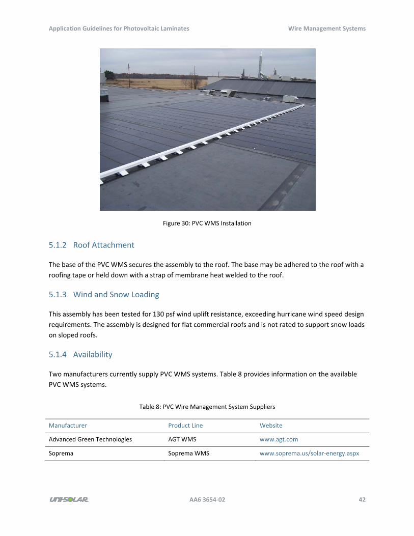
Application Guidelines for Photovoltaic Laminates Wire Management Systems
AA6 3654‐02 42
Figure 30: PVC WMS Installation
5.1.2 Roof Attachment
The base of the PVC WMS secures the assembly to the roof. The base may be adhered to the roof with a
roofing tape or held down with a strap of membrane heat welded to the roof.
5.1.3 Wind and Snow Loading
This assembly has been tested for 130 psf wind uplift resistance, exceeding hurricane wind speed design
requirements. The assembly is designed for flat commercial roofs and is not rated to support snow loads
on sloped roofs.
5.1.4 Availability
Two manufacturers currently supply PVC WMS systems. Table 8 provides information on the available
PVC WMS systems.
Table 8: PVC Wire Management System Suppliers
Manufacturer Product Line Website
Advanced Green Technologies AGT WMS www.agt.com
Soprema Soprema WMS www.soprema.us/solar‐energy.aspx
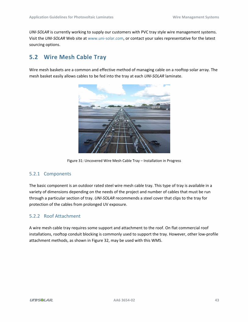
Application Guidelines for Photovoltaic Laminates Wire Management Systems
AA6 3654‐02 43
UNI‐SOLAR is currently working to supply our customers with PVC tray style wire management systems.
Visit the UNI‐SOLAR Web site at www.uni‐solar.com, or contact your sales representative for the latest
sourcing options.
5.2 Wire Mesh Cable Tray
Wire mesh baskets are a common and effective method of managing cable on a rooftop solar array. The
mesh basket easily allows cables to be fed into the tray at each UNI‐SOLAR laminate.
Figure 31: Uncovered Wire Mesh Cable Tray – Installation in Progress
5.2.1 Components
The basic component is an outdoor rated steel wire mesh cable tray. This type of tray is available in a
variety of dimensions depending on the needs of the project and number of cables that must be run
through a particular section of tray. UNI‐SOLAR recommends a steel cover that clips to the tray for
protection of the cables from prolonged UV exposure.
5.2.2 Roof Attachment
A wire mesh cable tray requires some support and attachment to the roof. On flat commercial roof
installations, rooftop conduit blocking is commonly used to support the tray. However, other low‐profile
attachment methods, as shown in Figure 32, may be used with this WMS.
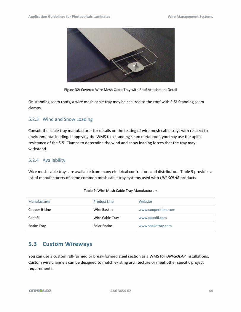
Application Guidelines for Photovoltaic Laminates Wire Management Systems
AA6 3654‐02 44
Figure 32: Covered Wire Mesh Cable Tray with Roof Attachment Detail
On standing seam roofs, a wire mesh cable tray may be secured to the roof with S‐5! Standing seam
clamps.
5.2.3 Wind and Snow Loading
Consult the cable tray manufacturer for details on the testing of wire mesh cable trays with respect to
environmental loading. If applying the WMS to a standing seam metal roof, you may use the uplift
resistance of the S‐5! Clamps to determine the wind and snow loading forces that the tray may
withstand.
5.2.4 Availability
Wire mesh cable trays are available from many electrical contractors and distributors. Table 9 provides a
list of manufacturers of some common mesh cable tray systems used with UNI‐SOLAR products.
Table 9: Wire Mesh Cable Tray Manufacturers
Manufacturer Product Line Website
Cooper B‐Line Wire Basket www.cooperbline.com
Cabofil Wire Cable Tray www.cabofil.com
Snake Tray Solar Snake www.snaketray.com
5.3 Custom Wireways
You can use a custom roll‐formed or break‐formed steel section as a WMS for UNI‐SOLAR installations.
Custom wire channels can be designed to match existing architecture or meet other specific project
requirements.
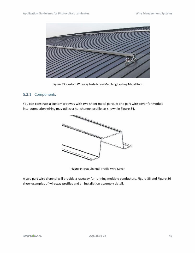
Application Guidelines for Photovoltaic Laminates Wire Management Systems
AA6 3654‐02 45
Figure 33: Custom Wireway Installation Matching Existing Metal Roof
5.3.1 Components
You can construct a custom wireway with two sheet metal parts. A one part wire cover for module
interconnection wiring may utilize a hat channel profile, as shown in Figure 34.
Figure 34: Hat Channel Profile Wire Cover
A two part wire channel will provide a raceway for running multiple conductors. Figure 35 and Figure 36
show examples of wireway profiles and an installation assembly detail.
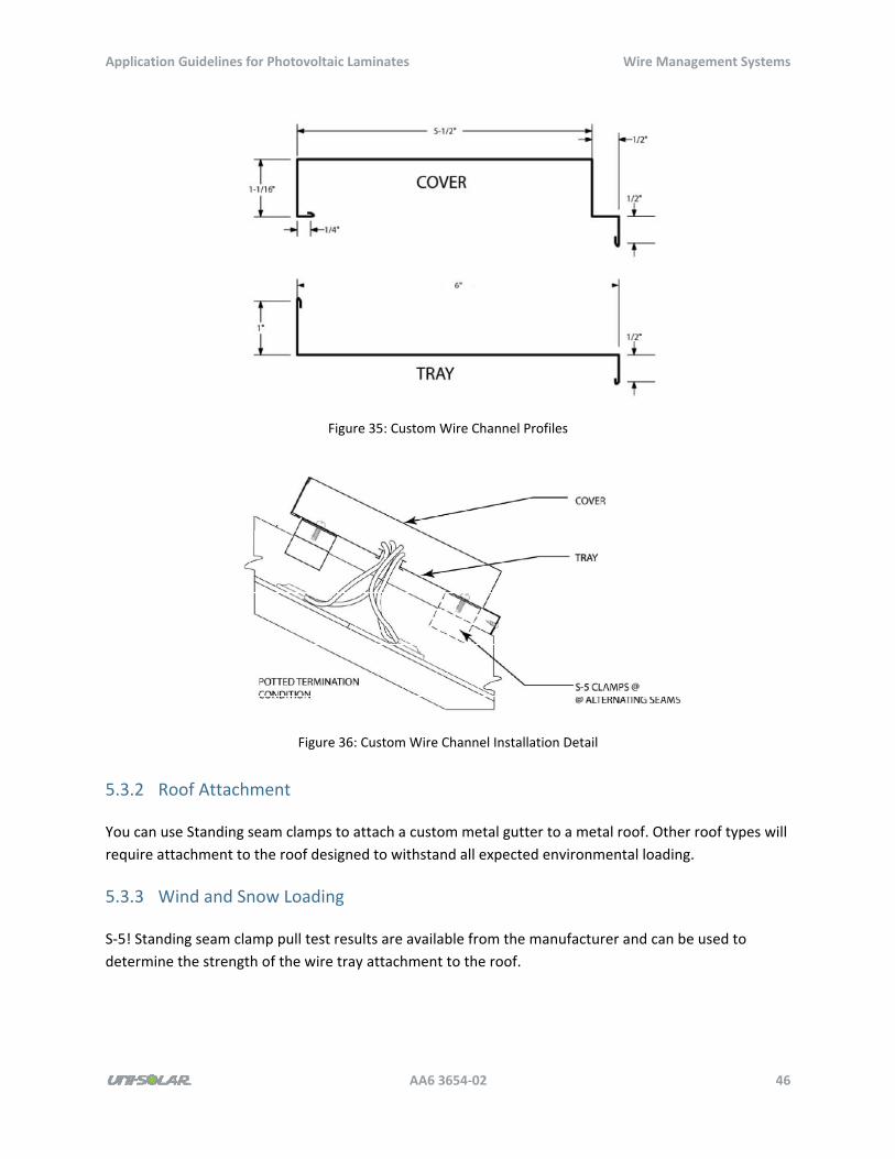
Application Guidelines for Photovoltaic Laminates Wire Management Systems
AA6 3654‐02 46
Figure 35: Custom Wire Channel Profiles
Figure 36: Custom Wire Channel Installation Detail
5.3.2 Roof Attachment
You can use Standing seam clamps to attach a custom metal gutter to a metal roof. Other roof types will
require attachment to the roof designed to withstand all expected environmental loading.
5.3.3 Wind and Snow Loading
S‐5! Standing seam clamp pull test results are available from the manufacturer and can be used to
determine the strength of the wire tray attachment to the roof.
Application Guidelines for Photovoltaic Laminates Wire Management Systems
AA6 3654‐02 47
5.3.4 Availability
Metal shops and many roofing contractors have sheet metal forming equipment that can produce the
custom wireway required for a UNI‐SOLAR project.
Application Guidelines for Photovoltaic Laminates Construction Overview and Scheduling
AA6 3654‐02 48
6 Construction Overview and Scheduling
This chapter provides best practices, recommendations, and guidelines for planning a successful UNI‐
SOLAR project. The UNI‐SOLAR installation guides contain the installation specifications and should be
consulted for all installation requirements.
6.1 Handling and Storage
All specifications and requirements of the UNI‐SOLAR installation guides apply to the installation the
UNI‐SOLAR laminates. Contractors should carefully consider the storage of the laminates prior to the
site installation. The laminates are shipped in 4’ x 4’ x 17” boxes. PVL series boxes must not be stacked
more than three boxes high, while ePVL series boxes may be stacked 4 high. Laminates must be kept in a
dry, clean warehouse‐type facility prior to installation, with ambient temperatures between 15° C (59° F)
and 30° C (86° F). Contractors should choose a storage location close to the job site if available to avoid
excess transportation costs and excessive handling.
6.2 Logistics
You should discuss the following items and finalize them during the logistics period:
Loading areas
Construction access
Dumpster locations
Access to roof (any special requirements from the owner)
Parking areas for construction vehicles
Noise levels
Daily cleanup
Working hours
Supervision
Power source
Water source
Building access, if required
On‐site storage, if required
Figure 37 shows an example of a logistics plan that was utilized at a North American project of ~880 kW
installation.
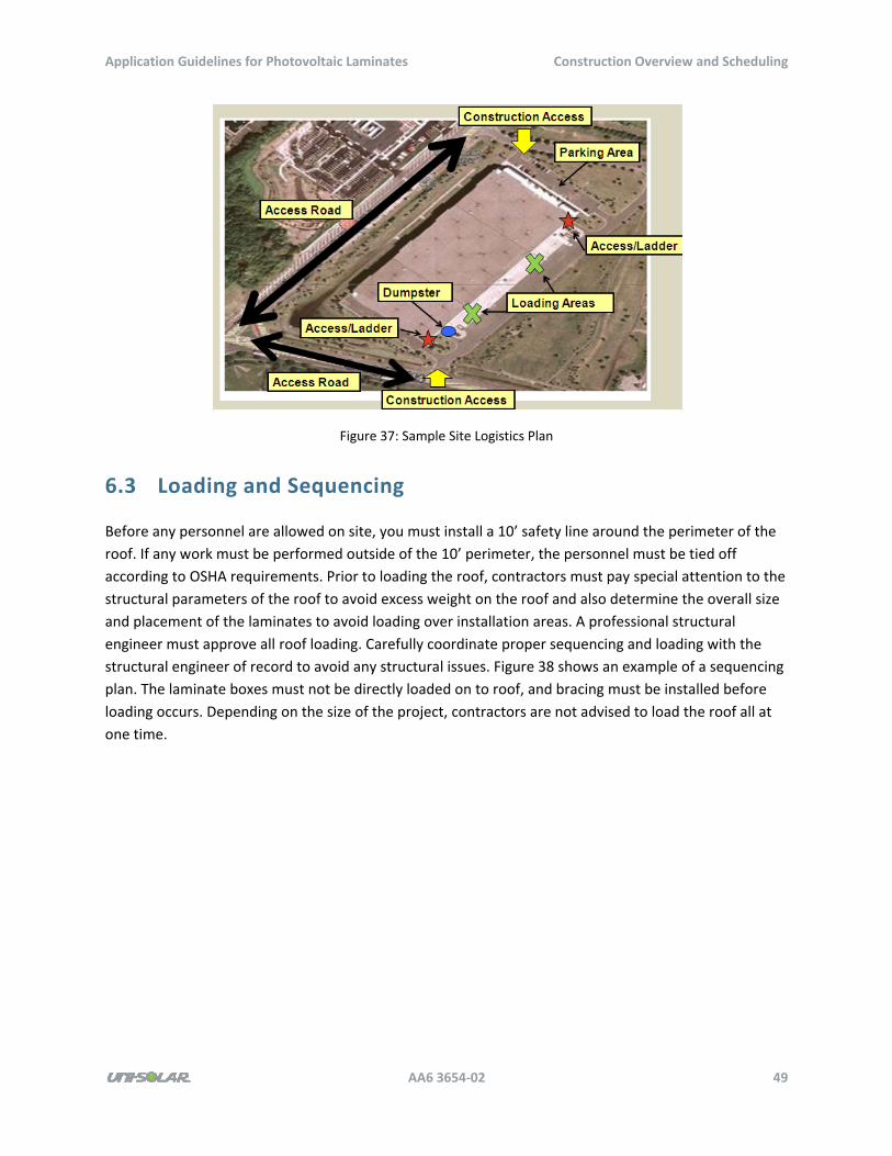
Application Guidelines for Photovoltaic Laminates Construction Overview and Scheduling
AA6 3654‐02 49
Figure 37: Sample Site Logistics Plan
6.3 Loading and Sequencing
Before any personnel are allowed on site, you must install a 10’ safety line around the perimeter of the
roof. If any work must be performed outside of the 10’ perimeter, the personnel must be tied off
according to OSHA requirements. Prior to loading the roof, contractors must pay special attention to the
structural parameters of the roof to avoid excess weight on the roof and also determine the overall size
and placement of the laminates to avoid loading over installation areas. A professional structural
engineer must approve all roof loading. Carefully coordinate proper sequencing and loading with the
structural engineer of record to avoid any structural issues. Figure 38 shows an example of a sequencing
plan. The laminate boxes must not be directly loaded on to roof, and bracing must be installed before
loading occurs. Depending on the size of the project, contractors are not advised to load the roof all at
one time.
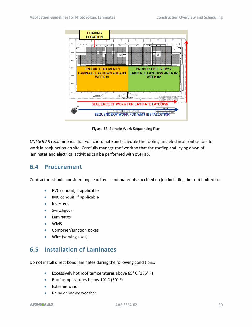
Application Guidelines for Photovoltaic Laminates Construction Overview and Scheduling
AA6 3654‐02 50
Figure 38: Sample Work Sequencing Plan
UNI‐SOLAR recommends that you coordinate and schedule the roofing and electrical contractors to
work in conjunction on site. Carefully manage roof work so that the roofing and laying down of
laminates and electrical activities can be performed with overlap.
6.4 Procurement
Contractors should consider long lead items and materials specified on job including, but not limited to:
PVC conduit, if applicable
IMC conduit, if applicable
Inverters
Switchgear
Laminates
WMS
Combiner/junction boxes
Wire (varying sizes)
6.5 Installation of Laminates
Do not install direct bond laminates during the following conditions:
Excessively hot roof temperatures above 85° C (185° F)
Roof temperatures below 10° C (50° F)
Extreme wind
Rainy or snowy weather
Application Guidelines for Photovoltaic Laminates Construction Overview and Scheduling
AA6 3654‐02 51
You should also consider the following additional items during the laminate installation on the roof:
Walkways, if required
Flagging (for WMS/combiner box identification), if required
Ramps (to avoid breaking WMS), if required
6.6 Electrical Activities
If available, there should be two electrical crews working the following activities to accelerate the
schedule (ground work and rooftop work):
Ground‐level electrical work includes trenching at inverters, installation of conduit,
backfilling, setting of pads and inverters, installation of the switchgear and metering,
installation of the monitoring equipment, and tapping into existing switchboard.
Roof‐level electrical work includes installation of vertical conduit, loading of electrical
material, installation of horizontal conduit, installation of WMS, connection of PV panels,
pulling of horizontal wire, pulling of down leads, installation of wire harness, wiring of
combiner boxes, and termination and splicing of cables.
6.7 Commissioning
Commissioning a UNI‐SOLAR array is critical to the success of the project. Personnel on site must be
trained to commission the system properly to verify functionality and performance expectations. You
must establish commissioning and performance parameters at the onset of each project.
6.8 Scheduling
Compile a detailed schedule prior to the start of the project, and include the following important
scheduling items:
Permitting
Utility inspections
SREC submissions, if applicable
State permits, if applicable
Zoning permit
Procurement
Mobilization
Re‐roofing, if applicable
Roof delivery
Installation of UNI‐SOLAR laminates
Rooftop electrical (WMS, combiner boxes, junction boxes, conduits, etc.)
Interconnection electrical work
Application Guidelines for Photovoltaic Laminates Construction Overview and Scheduling
AA6 3654‐02 52
Utility shut‐down, if required
Final cleanup
Final inspections (utility, state, SREC, etc.)
In general, schedule activities should be specific, measurable, achievable, realistic, and clearly timed
(SMART).
Be sure to consider weather and union vs. non‐union labor depending on the section of the country, as
cost and labor productivity will be impacted by it.
Refer to Appendix D: Sample Schedule for a sample schedule.

Application Guidelines for Photovoltaic Laminates Application Certifications
AA6 3654‐02 53
7 Application Certifications
UNI‐SOLAR products have been certified by nationally recognized testing laboratories to many standards
worldwide pertaining to photovoltaic equipment safety and reliability. The following is a list of standards
to which UNI‐SOLAR products have been tested, the testing agency, and status of the listing.
7.1 UL 1703 Flat‐Plate PV Modules and Panels
Products tested by Underwriters Laboratories:
PVL and ePVL products are certified to UL 1703.
UNI‐SOLAR PVL and ePVL products are listed by UL and marked with Underwriters
Laboratories (UL) and Canadian Underwriters Laboratories (cUL) marks
Products tested by Intertek ETL:
PowerTilt products are certified by Intertek ETL to UL 1703.
7.2 UL 790 Fire Tests of Roof Coverings
Products tested by Underwriters Laboratories:
PVL and ePVL products are certified with particular roof materials and assemblies to UL 790
Fire classification depends on slope and roof assembly. Class A rated assemblies are
available, with other assemblies categorized as Class B and C.
UNI‐SOLAR PVL and ePVL products are listed by UL and marked with Underwriters
Laboratories (UL) and Canadian Underwriters Laboratories (cUL) marks
7.3 ICC AC‐365 Acceptance Criteria for BIPV Roof Modules and
Panels
Product tested by International Code Council Evaluation Service:
Testing to AC‐365 has been completed and certification is in progress.
Application Guidelines for Photovoltaic Laminates Application Certifications
AA6 3654‐02 54
7.4 CEC SB1 Guidelines for California’s Solar Electric Incentive
Programs
Products tested by KEMA:
PVL, ePVL, and PowerTilt products are listed on the CEC eligible modules list.
7.5 Miami‐Dade Notice of Acceptance
Products tested by Trinity ERD
Factory assembled Solar‐Mat (PowerMembrane Application – see Section 2.2) has a current
Miami‐Dade NOA
Direct bond to metal roofs (see Section 2.3) is under review by Miami‐Dade and NOA is
expected to be issued
Direct bond to membrane (see section 2.1) and bonding to a removable secondary
membrane in the field (see Section 2.2) is under review by Miami‐Dade and NOA is expected
to be issued
7.6 IEC 61646 Thin‐film Terrestrial PV Modules and IEC 61730
and PV Module Safety Qualification
Products tested by TUV Rheinland:
UNI‐SOLAR PVL and ePVL products are marked with the TUV mark.
7.7 Korea: KEMCO Korean Energy Management Corporation
Products tested by KTL/KEMCO:
The PVL product is currently approved.
ePVL approval testing is in progress.
7.8 Brazil: IEE‐USP
Product tested by INMETRO:
The PVL product is currently approved.
Application Guidelines for Photovoltaic Laminates Application Certifications
AA6 3654‐02 55
7.9 Puerto Rico: AEE
Products tested by AEE:
The PVL product is currently approved.
ePVL approval testing is in progress.
7.10 United Kingdom: MCS Microgeneration Certification Scheme
Products tested by BRE Global:
The PVL and ePVL products are currently approved.
Application Guidelines for Photovoltaic Laminates PowerBond Estimating Reference
AA6 3654‐02 56
Appendix A: PowerBond Estimating
Reference
UNI‐SOLAR PowerBond PV laminates may be applied directly to a new roof membrane or newly installed
layer of roofing membrane, provided that you comply with all substrate material and installation
specifications documented in the UNI‐SOLAR installation guides.
This appendix provides project developers and construction estimators with a case study for a
commercial scale PowerBond installation and reference material to support building a project estimate.
A.1 Project Description
This case study examines rooftop PV system construction at the PowerBond Project 1 property in North
America. The PV system capacity is ~880 kW DC and features (6,127) UNI‐SOLAR PVL‐144 PowerBond
laminates. UNI‐SOLAR laminates were installed on a new Carlisle EPDM membrane roof.
A.2 Estimating Data
The estimating data in Table 10 is taken from daily reports submitted by UNI‐SOLAR field personnel. The
scope of work encompasses installation of the UNI‐SOLAR PVL‐144 laminates and installation of the wire
management tray bases by a labor crew.
Early in the project, a slower installation rate typical of a local labor installation with experienced
supervision and training was observed. As the installation progressed, the crew ran more efficiently and
hit a better run‐rate.
Table 10: Typical Installation Rates for UNI‐SOLAR PVL on Membrane
kW/Day Crew
Total
Hours
kW per
man‐hour
kW per
man‐day
# PVL per
man‐hour
# PVL per
man day
Ramp‐up 57 11 88 0.65 5.18 4.50 35.98
Optimal Rate 89 11 88 1.01 8.05 6.99 55.91
Application Guidelines for Photovoltaic Laminates PowerMembrane Estimating Reference
AA6 3654‐02 57
Appendix B: PowerMembrane Estimating
Reference
UNI‐SOLAR PowerMembrane PV laminates may be applied directly to a secondary layer of single‐ply
roofing membrane which is attached to the existing roof in such a way that the membrane and UNI‐
SOLAR laminates may be removed, leaving the existing roof intact.
This appendix provides project developers and construction estimators with a case study for a
commercial scale PowerMembrane installation and reference material to support building a project
estimate.
B.1 Project Description
This case study examines rooftop PV system construction at the PowerMembrane Project 1 property in
North America. The PV system capacity is ~80 kW DC and features (6,754) UNI‐SOLAR PVL‐144
laminates. UNI‐SOLAR laminates were installed on a new Carlisle EPDM membrane.
B.2 Estimating Data
The estimating data in Table 11 is taken from daily reports submitted by UNI‐SOLAR field personnel. The
scope of work encompasses installation of the UNI‐SOLAR PVL‐144 laminates. Figure 39 shows installed
modules and the pallets of UNI‐SOLAR laminates handled/staged for installation. Note that there is
additional time associated with the mat installation (typically seven laminates per mat) performed inside
a control warehouse‐type environment. This document does not include the mat production.
Early in the project, a slower installation rate typical of a local labor installation with experienced
supervision and training was observed. As the installation progressed, the crew ran more efficiently and
hit a better run‐rate.
Table 11: Typical Installation Rates for UNI‐SOLAR PVL on Mats
kW/Day Crew
Total
Hours
kW per
man‐hour
kW per
man‐day
# PVL per
man‐hour
# PVL per
man day
Ramp‐up and Overall project 44.6 16.5 132 0.34 2.73 2.37 18.93
Application Guidelines for Photovoltaic Laminates PowerMembrane Estimating Reference
AA6 3654‐02 58
Figure 39: Installed UNI‐SOLAR PowerMembrane Array
Figure 40: Installation of PowerMembrane in Progress
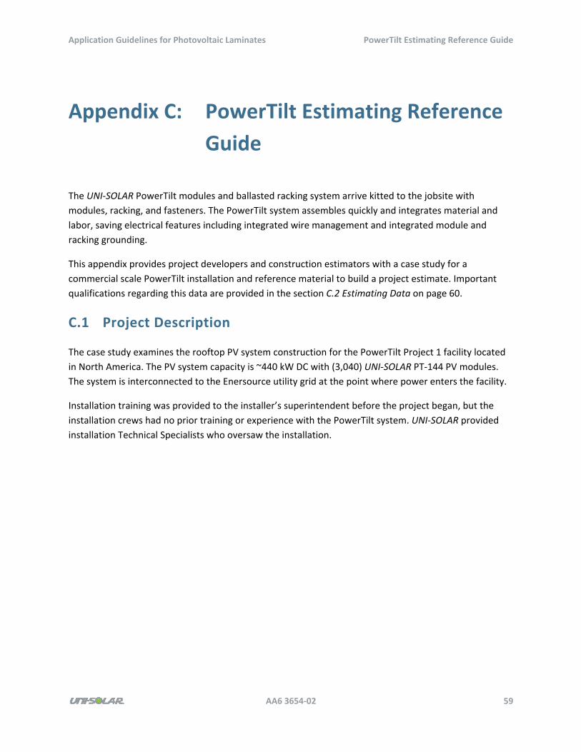
Application Guidelines for Photovoltaic Laminates PowerTilt Estimating Reference Guide
AA6 3654‐02 59
Appendix C: PowerTilt Estimating Reference
Guide
The UNI‐SOLAR PowerTilt modules and ballasted racking system arrive kitted to the jobsite with
modules, racking, and fasteners. The PowerTilt system assembles quickly and integrates material and
labor, saving electrical features including integrated wire management and integrated module and
racking grounding.
This appendix provides project developers and construction estimators with a case study for a
commercial scale PowerTilt installation and reference material to build a project estimate. Important
qualifications regarding this data are provided in the section C.2 Estimating Data on page 60.
C.1 Project Description
The case study examines the rooftop PV system construction for the PowerTilt Project 1 facility located
in North America. The PV system capacity is ~440 kW DC with (3,040) UNI‐SOLAR PT‐144 PV modules.
The system is interconnected to the Enersource utility grid at the point where power enters the facility.
Installation training was provided to the installer’s superintendent before the project began, but the
installation crews had no prior training or experience with the PowerTilt system. UNI‐SOLAR provided
installation Technical Specialists who oversaw the installation.
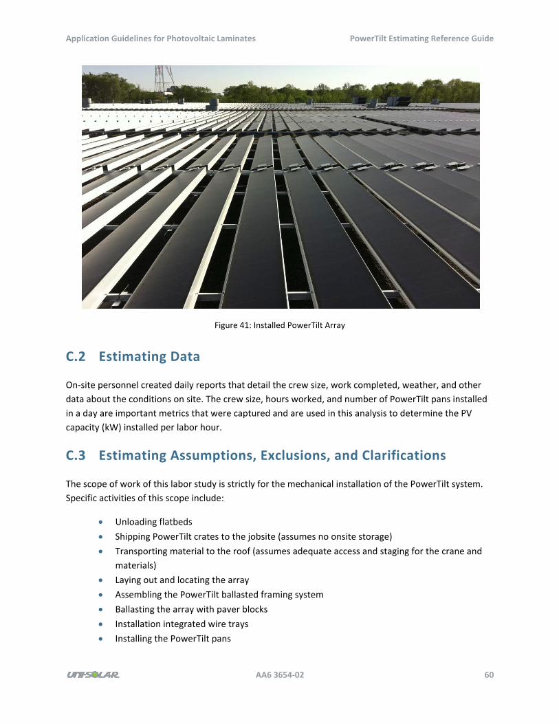
Application Guidelines for Photovoltaic Laminates PowerTilt Estimating Reference Guide
AA6 3654‐02 60
Figure 41: Installed PowerTilt Array
C.2 Estimating Data
On‐site personnel created daily reports that detail the crew size, work completed, weather, and other
data about the conditions on site. The crew size, hours worked, and number of PowerTilt pans installed
in a day are important metrics that were captured and are used in this analysis to determine the PV
capacity (kW) installed per labor hour.
C.3 Estimating Assumptions, Exclusions, and Clarifications
The scope of work of this labor study is strictly for the mechanical installation of the PowerTilt system.
Specific activities of this scope include:
Unloading flatbeds
Shipping PowerTilt crates to the jobsite (assumes no onsite storage)
Transporting material to the roof (assumes adequate access and staging for the crane and
materials)
Laying out and locating the array
Assembling the PowerTilt ballasted framing system
Ballasting the array with paver blocks
Installation integrated wire trays
Installing the PowerTilt pans
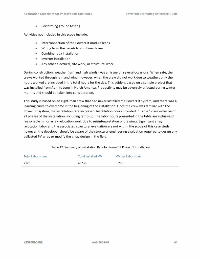
Application Guidelines for Photovoltaic Laminates PowerTilt Estimating Reference Guide
AA6 3654‐02 61
Performing ground testing
Activities not included in this scope include:
Interconnection of the PowerTilt module leads
Wiring from the panels to combiner boxes
Combiner box installation
Inverter installation
Any other electrical, site work, or structural work
During construction, weather (rain and high winds) was an issue on several occasions. When safe, the
crews worked through rain and wind; however, when the crew did not work due to weather, only the
hours worked are included in the total hours for the day. This guide is based on a sample project that
was installed from April to June in North America. Productivity may be adversely affected during winter
months and should be taken into consideration.
This study is based on an eight‐man crew that had never installed the PowerTilt system, and there was a
learning curve to overcome in the beginning of the installation. Once the crew was familiar with the
PowerTilt system, the installation rate increased. Installation hours provided in Table 12 are inclusive of
all phases of the installation, including ramp‐up. The labor hours presented in the table are inclusive of
reasonable minor array relocation work due to misinterpretation of drawings. Significant array
relocation labor and the associated structural evaluation are not within the scope of this case study;
however, the developer should be aware of the structural engineering evaluation required to design any
ballasted PV array or modify the array design in the field.
Table 12: Summary of Installation Rate for PowerTilt Project 1 Installation
Total Labor Hours Total Installed kW kW per Labor Hour
2126. 437.76 0.206

Application Guidelines for Photovoltaic Laminates Sample Schedule
AA6 3654‐02 62
Appendix D: Sample Schedule
The content in this appendix shows an example of a schedule. The example begins on the next page
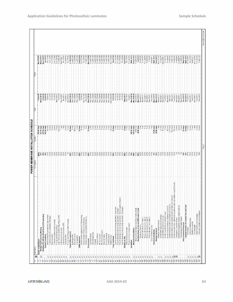
Application Guidelines for Photovoltaic Laminates Sample Schedule
AA6 3654‐02 63
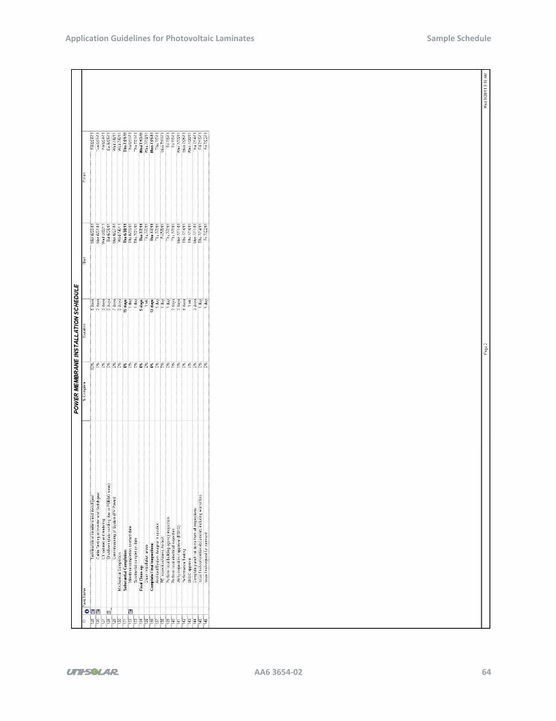
Application Guidelines for Photovoltaic Laminates Sample Schedule
AA6 3654‐02 64
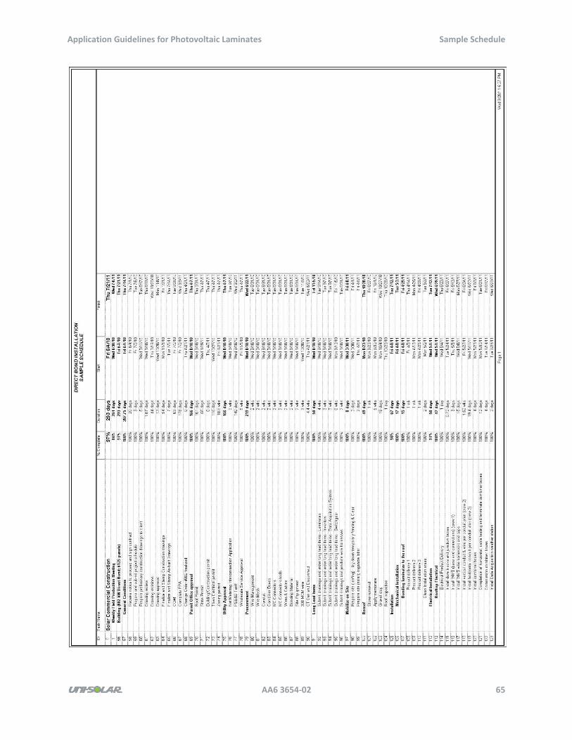
Application Guidelines for Photovoltaic Laminates Sample Schedule
AA6 3654‐02 65
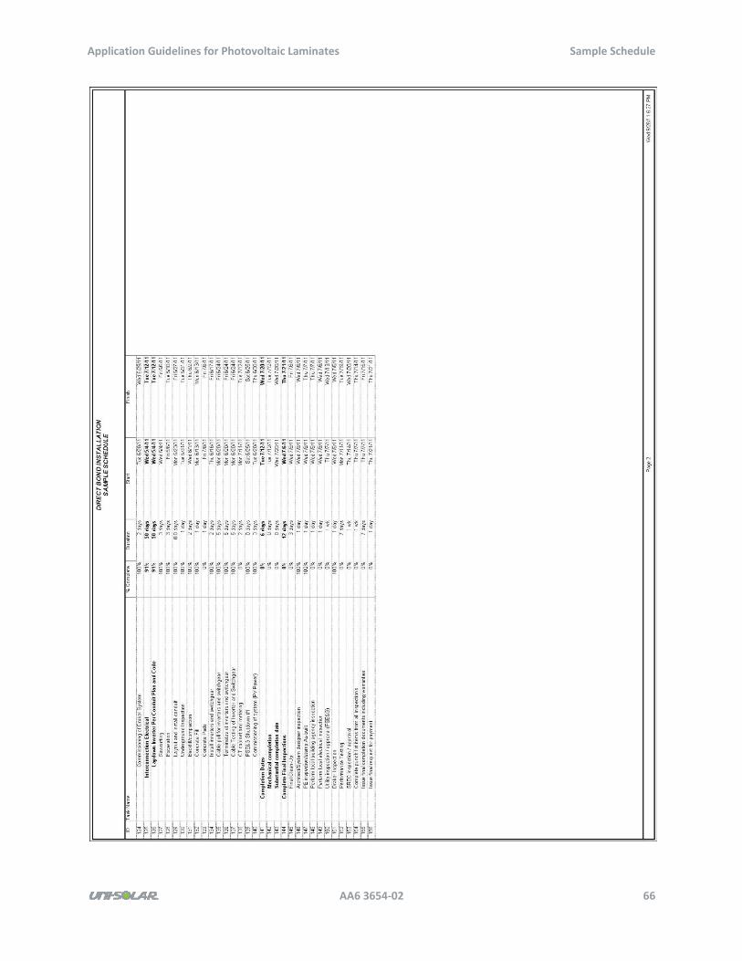
Application Guidelines for Photovoltaic Laminates Sample Schedule
AA6 3654‐02 66
Application Guidelines for Photovoltaic Laminates Application Selection Flowchart
AA6 3654‐02 67
Appendix E: Application Selection Flowchart
This appendix contains an application selection flowchart. The flowchart begins on the next page.
Application Guidelines for Photovoltaic Laminates Application Selection Flowchart
AA6 3654‐02 68
Application Guidelines for Photovoltaic Laminates Application Selection Flowchart
AA6 3654‐02 69
Application Guidelines for Photovoltaic Laminates Application Selection Flowchart
AA6 3654‐02 70
Application Guidelines for Photovoltaic Laminates Application Selection Flowchart
AA6 3654‐02 71