CHAPTER 2-1 Catalyst 2960 Switch Command Reference OL-8604-07 2 Catalyst 2960 Switch Cisco IOS Commands aaa accounting dot1x Use the aaa accounting dot1x global configuration command to enable authentication, authorization, and accounting (AAA) accounting and to create method lists defining specific accounting methods on a per-line or per-interface basis for IEEE 802.1x sessions. Use the no form of this command to disable IEEE 802.1x accounting. aaa accounting dot1x {name | default} start-stop {broadcast group {name | radius | tacacs+} [group {name | radius | tacacs+}...] | group {name | radius | tacacs+} [group {name | radius | tacacs+}...]} no aaa accounting dot1x {name | default} Syntax Description name Name of a server group. This is optional when you enter it after the broadcast group and group keywords. default Use the accounting methods that follow as the default list for accounting services. start-stop Send a start accounting notice at the beginning of a process and a stop accounting notice at the end of a process. The start accounting record is sent in the background. The requested-user process begins regardless of whether or not the start accounting notice was received by the accounting server. broadcast Enable accounting records to be sent to multiple AAA servers and send accounting records to the first server in each group. If the first server is unavailable, the switch uses the list of backup servers to identify the first server. group Specify the server group to be used for accounting services. These are valid server group names: • name—Name of a server group. • radius—List of all RADIUS hosts. • tacacs+—List of all TACACS+ hosts. The group keyword is optional when you enter it after the broadcast group and group keywords. You can enter more than optional group keyword. radius (Optional) Enable RADIUS authorization. tacacs+ (Optional) Enable TACACS+ accounting.
Transcript
OL-8604-07
C H A P T E R 2
Catalyst 2960 Switch Cisco IOS Commands
aaa accounting dot1xUse the aaa accounting dot1x global configuration command to enable authentication, authorization, and accounting (AAA) accounting and to create method lists defining specific accounting methods on a per-line or per-interface basis for IEEE 802.1x sessions. Use the no form of this command to disable IEEE 802.1x accounting.
Syntax Description name Name of a server group. This is optional when you enter it after the broadcast group and group keywords.
default Use the accounting methods that follow as the default list for accounting services.
start-stop Send a start accounting notice at the beginning of a process and a stop accounting notice at the end of a process. The start accounting record is sent in the background. The requested-user process begins regardless of whether or not the start accounting notice was received by the accounting server.
broadcast Enable accounting records to be sent to multiple AAA servers and send accounting records to the first server in each group. If the first server is unavailable, the switch uses the list of backup servers to identify the first server.
group Specify the server group to be used for accounting services. These are valid server group names:
• name—Name of a server group.
• radius—List of all RADIUS hosts.
• tacacs+—List of all TACACS+ hosts.
The group keyword is optional when you enter it after the broadcast group and group keywords. You can enter more than optional group keyword.
Usage Guidelines This command requires access to a RADIUS server.
We recommend that you enter the dot1x reauthentication interface configuration command before configuring IEEE 802.1x RADIUS accounting on an interface.
Examples This example shows how to configure IEEE 802.1x accounting:
Switch(config)# aaa new-modelSwitch(config)# aaa accounting dot1x default start-stop group radius
Note The RADIUS authentication server must be properly configured to accept and log update or watchdog packets from the AAA client.
Related Commands
Release Modification
12.2(25)FX This command was introduced.
Command Description
aaa authentication dot1x
Specifies one or more AAA methods for use on interfaces running IEEE 802.1x.
aaa new-model Enables the AAA access control model. For syntax information, see the Cisco IOS Security Command Reference, Release 12.2 > Authentication, Authorization, and Accounting > Authentication Commands.
dot1x reauthentication Enables or disables periodic reauthentication.
dot1x timeout reauth-period
Sets the number of seconds between re-authentication attempts.
aaa authentication dot1xUse the aaa authentication dot1x global configuration command to specify the authentication, authorization, and accounting (AAA) method to use on ports complying with the IEEE 802.1x authentication. Use the no form of this command to disable authentication.
aaa authentication dot1x {default} method1
no aaa authentication dot1x {default}
Syntax Description
Note Though other keywords are visible in the command-line help strings, only the default and group radius keywords are supported.
Defaults No authentication is performed.
Command Modes Global configuration
Command History
Usage Guidelines The method argument identifies the method that the authentication algorithm tries in the given sequence to validate the password provided by the client. The only method that is truly IEEE 802.1x-compliant is the group radius method, in which the client data is validated against a RADIUS authentication server.
If you specify group radius, you must configure the RADIUS server by entering the radius-server host global configuration command.
Use the show running-config privileged EXEC command to display the configured lists of authentication methods.
Examples This example shows how to enable AAA and how to create an IEEE 802.1x-compliant authentication list. This authentication first tries to contact a RADIUS server. If this action returns an error, the user is not allowed access to the network.
Switch(config)# aaa new-modelSwitch(config)# aaa authentication dot1x default group radius
You can verify your settings by entering the show running-config privileged EXEC command.
default Use the listed authentication method that follows this argument as the default method when a user logs in.
method1 Enter the group radius keywords to use the list of all RADIUS servers for authentication.
aaa new-model Enables the AAA access control model. For syntax information, see the Cisco IOS Security Command Reference, Release 12.2 > Authentication, Authorization, and Accounting > Authentication Commands.
show running-config Displays the current operating configuration. For syntax information, select Cisco IOS Configuration Fundamentals Command Reference, Release 12.2 > File Management Commands > Configuration File Management Commands.
aaa authorization network Use the aaa authorization network global configuration command to the configure the switch to use user-RADIUS authorization for all network-related service requests, such as IEEE 802.1x VLAN assignment. Use the no form of this command to disable RADIUS user authorization.
aaa authorization network default group radius
no aaa authorization network default
Syntax Description
Defaults Authorization is disabled.
Command Modes Global configuration
Command History
Usage Guidelines Use the aaa authorization network default group radius global configuration command to allow the switch to download IEEE 802.1x authorization parameters from the RADIUS servers in the default authorization list. The authorization parameters are used by features such as VLAN assignment to get parameters from the RADIUS servers.
Use the show running-config privileged EXEC command to display the configured lists of authorization methods.
Examples This example shows how to configure the switch for user RADIUS authorization for all network-related service requests:
Switch(config)# aaa authorization network default group radius
You can verify your settings by entering the show running-config privileged EXEC command.
Related Commands
default group radius
Use the list of all RADIUS hosts in the server group as the default authorization list.
Release Modification
12.2(25)FX This command was introduced.
Command Description
show running-config Displays the current operating configuration. For syntax information, select Cisco IOS Configuration Fundamentals Command Reference, Release 12.2 > File Management Commands > Configuration File Management Commands.
archive download-swUse the archive download-sw privileged EXEC command to download a new image from a TFTP server to the switch and to overwrite or keep the existing image.
Syntax Description /directory Specify a directory for the images.
/force-reload Unconditionally force a system reload after successfully downloading the software image.
/imageonly Download only the software image but not the HTML files associated with the embedded device manager. The HTML files for the existing version are deleted only if the existing version is being overwritten or removed.
/leave-old-sw Keep the old software version after a successful download.
/no-set-boot Do not alter the setting of the BOOT environment variable to point to the new software image after it is successfully downloaded.
/no-version-check Download the software image without verifying its version compatibility with the image that is running on the switch.
/overwrite Overwrite the software image in flash memory with the downloaded image.
/reload Reload the system after successfully downloading the image unless the configuration has been changed and not saved.
/safe Keep the current software image. Do not delete it to make room for the new software image before the new image is downloaded. The current image is deleted after the download.
Defaults The current software image is not overwritten with the downloaded image.
Both the software image and HTML files are downloaded.
The new image is downloaded to the flash: file system.
The BOOT environment variable is changed to point to the new software image on the flash: file system.
Image names are case sensitive; the image file is provided in tar format.
Command Modes Privileged EXEC
Command History
Usage Guidelines The /imageonly option removes the HTML files for the existing image if the existing image is being removed or replaced. Only the Cisco IOS image (without the HTML files) is downloaded.
Using the /safe or /leave-old-sw option can cause the new image download to fail if there is insufficient flash memory. If leaving the software in place prevents the new image from fitting in flash memory due to space constraints, an error results.
If you used the /leave-old-sw option and did not overwrite the old image when you downloaded the new one, you can remove the old image by using the delete privileged EXEC command. For more information, see the “delete” section on page 2-97.
source-url The source URL alias for a local or network file system. These options are supported:
• The syntax for the secondary boot loader (BS1):bs1:
• The syntax for the local flash file system:flash:
• The syntax for the FTP: ftp:[[//username[:password]@location]/directory]/image-name.tar
• The syntax for an HTTP server:http://[[username:password]@]{hostname | host-ip}[/directory]/image-name.tar
• The syntax for a secure HTTP server:https://[[username:password]@]{hostname | host-ip}[/directory]/image-name.tar
• The syntax for the Remote Copy Protocol (RCP): rcp:[[//username@location]/directory]/image-name.tar
• The syntax for the TFTP:tftp:[[//location]/directory]/image-name.tar
The image-name.tar is the software image to download and install on the switch.
Use the /overwrite option to overwrite the image on the flash device with the downloaded one.
If you specify the command without the /overwrite option, the download algorithm verifies that the new image is not the same as the one on the switch flash device. If the images are the same, the download does not occur. If the images are different, the old image is deleted, and the new one is downloaded.
After downloading a new image, enter the reload privileged EXEC command to begin using the new image, or specify the /reload or /force-reload option in the archive download-sw command.
Examples This example shows how to download a new image from a TFTP server at 172.20.129.10 and to overwrite the image on the switch:
Create a new tar file on the local or network file system.
For destination-url, specify the destination URL alias for the local or network file system and the name of the tar file to create. These options are supported:
• The syntax for the local flash filesystem:flash:
• The syntax for the FTP: ftp:[[//username[:password]@location]/directory]/tar-filename.tar
• The syntax for an HTTP server:http://[[username:password]@]{hostname | host-ip}[/directory]/image-name.tar
• The syntax for a secure HTTP server:https://[[username:password]@]{hostname | host-ip}[/directory]/image-name.tar
• The syntax for the Remote Copy Protocol (RCP) is: rcp:[[//username@location]/directory]/tar-filename.tar
• The syntax for the TFTP: tftp:[[//location]/directory]/tar-filename.tar
The tar-filename.tar is the tar file to be created.
For flash:/file-url, specify the location on the local flash file system from which the new tar file is created.
An optional list of files or directories within the source directory can be specified to write to the new tar file. If none are specified, all files and directories at this level are written to the newly created tar file.
2-9Catalyst 2960 Switch Command Reference
OL-8604-07
Chapter 2 Catalyst 2960 Switch Cisco IOS Commandsarchive tar
Defaults There is no default setting.
/table source-url Display the contents of an existing tar file to the screen.
For source-url, specify the source URL alias for the local or network file system. These options are supported:
• The syntax for the local flash file system:flash:
• The syntax for the FTP:ftp:[[//username[:password]@location]/directory]/tar-filename.tar
• The syntax for an HTTP server:http://[[username:password]@]{hostname | host-ip}[/directory]/image-name.tar
• The syntax for a secure HTTP server:https://[[username:password]@]{hostname | host-ip}[/directory]/image-name.tar
• The syntax for the RCP: rcp:[[//username@location]/directory]/tar-filename.tar
• The syntax for the TFTP: tftp:[[//location]/directory]/tar-filename.tar
The tar-filename.tar is the tar file to display.
/xtract source-url flash:/file-url [dir/file...]
Extract files from a tar file to the local file system.
For source-url, specify the source URL alias for the local file system. These options are supported:
• The syntax for the local flash file system:flash:
• The syntax for the FTP: ftp:[[//username[:password]@location]/directory]/tar-filename.tar
• The syntax for an HTTP server:http://[[username:password]@]{hostname | host-ip}[/directory]/image-name.tar
• The syntax for a secure HTTP server:https://[[username:password]@]{hostname | host-ip}[/directory]/image-name.tar
• The syntax for the RCP: rcp:[[//username@location]/directory]/tar-filename.tar
• The syntax for the TFTP: tftp:[[//location]/directory]/tar-filename.tar
The tar-filename.tar is the tar file from which to extract.
For flash:/file-url [dir/file...], specify the location on the local flash file system into which the tar file is extracted. Use the dir/file... option to specify an optional list of files or directories within the tar file to be extracted. If none are specified, all files and directories are extracted.
2-10Catalyst 2960 Switch Command Reference
OL-8604-07
Chapter 2 Catalyst 2960 Switch Cisco IOS Commandsarchive tar
Command Modes Privileged EXEC
Command History
Usage Guidelines Filenames and directory names are case sensitive.
Image names are case sensitive.
Examples This example shows how to create a tar file. The command writes the contents of the new-configs directory on the local flash device to a file named saved.tar on the TFTP server at 172.20.10.30:
Switch# archive tar /create tftp:172.20.10.30/saved.tar flash:/new_configs
This example shows how to display the contents of the file that is in flash memory. The contents of the tar file appear on the screen:
Switch# archive tar /table flash:c2960-lanbase-tar.12-25.FX.tarinfo (219 bytes)
This example shows how to extract the contents of a tar file on the TFTP server at 172.20.10.30. This command extracts just the new-configs directory into the root directory on the local flash file system. The remaining files in the saved.tar file are ignored.
Switch# archive tar /xtract tftp://172.20.10.30/saved.tar flash:/new-configs
Related Commands
Release Modification
12.2(25)FX This command was introduced.
Command Description
archive download-sw Downloads a new image from a TFTP server to the switch.
archive upload-sw Uploads an existing image on the switch to a server.
Defaults Uploads the currently running image from the flash file system.
Command Modes Privileged EXEC
Command History
Usage Guidelines Use the upload feature only if the HTML files associated with the embedded device manager have been installed with the existing image.
The files are uploaded in this sequence: the Cisco IOS image, the HTML files, and info. After these files are uploaded, the software creates the tar file.
Image names are case sensitive.
/version version_string (Optional) Specify the specific version string of the image to be uploaded.
destination-url The destination URL alias for a local or network file system. These options are supported:
• The syntax for the local flash file system:flash:
• The syntax for the FTP: ftp:[[//username[:password]@location]/directory]/image-name.tar
• The syntax for an HTTP server:http://[[username:password]@]{hostname | host-ip}[/directory]/image-name.tar
• The syntax for a secure HTTP server:https://[[username:password]@]{hostname | host-ip}[/directory]/image-name.tar
• The syntax for the Secure Copy Protocol (SCP):scp:[[//username@location]/directory]/image-name.tar
• The syntax for the Remote Copy Protocol (RCP): rcp:[[//username@location]/directory]/image-name.tar
• The syntax for the TFTP:tftp:[[//location]/directory]/image-name.tar
The image-name.tar is the name of software image to be stored on the server.
arp access-listUse the arp access-list global configuration command to define an Address Resolution Protocol (ARP) access control list (ACL) or to add clauses to the end of a previously defined list. Use the no form of this command to delete the specified ARP access list.
arp access-list acl-name
no arp access-list acl-name
Syntax Description
Defaults No ARP access lists are defined.
Command Modes Global configuration
Command History
Usage Guidelines After entering the arp access-list command, you enter ARP access-list configuration mode, and these configuration commands are available:
• default: returns a command to its default setting.
• deny: specifies packets to reject. For more information, see the “deny (ARP access-list configuration)” section on page 2-98.
• exit: exits ARP access-list configuration mode.
• no: negates a command or returns to default settings.
• permit: specifies packets to forward. For more information, see the “permit (ARP access-list configuration)” section on page 2-358.
Use the permit and deny access-list configuration commands to forward and to drop ARP packets based on the specified matching criteria.
When the ARP ACL is defined, you can apply it to a VLAN by using the ip arp inspection filter vlan global configuration command. ARP packets containing only IP-to-MAC address bindings are compared to the ACL. All other types of packets are bridged in the ingress VLAN without validation. If the ACL permits a packet, the switch forwards it. If the ACL denies a packet because of an explicit deny statement, the switch drops the packet. If the ACL denies a packet because of an implicit deny statement, the switch compares the packet to the list of DHCP bindings (unless the ACL is static, which means that packets are not compared to the bindings).
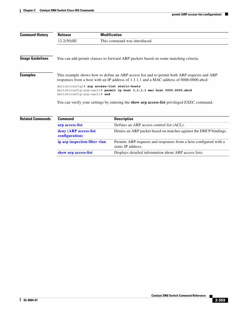
Examples This example shows how to define an ARP access list and to permit both ARP requests and ARP responses from a host with an IP address of 1.1.1.1 and a MAC address of 0000.0000.abcd:
Switch(config)# arp access-list static-hostsSwitch(config-arp-nacl)# permit ip host 1.1.1.1 mac host 00001.0000.abcdSwitch(config-arp-nacl)# end
You can verify your settings by entering the show arp access-list privileged EXEC command.
Related Commands Command Description
deny (ARP access-list configuration)
Denies an ARP packet based on matches compared against the DHCP bindings.
ip arp inspection filter vlan
Permits ARP requests and responses from a host configured with a static IP address.
permit (ARP access-list configuration)
Permits an ARP packet based on matches compared against the DHCP bindings.
show arp access-list Displays detailed information about ARP access lists.
authentication command bounce-port ignoreUse the authentication command bounce-port ignore global configuration command on the switch stack or on a standalone switch to allow the switch to ignore a command to temporarily disable a port. Use the no form of this command to return to the default status.
authentication command bounce-port ignore
no authentication command bounce-port ignore
Note To use this command, the switch must be running the LAN Base or IP Base image.
Syntax Description This command has no arguments or keywords.
Defaults The switch accepts a RADIUS Change of Authorization (CoA) bounce port command.
Command Modes Global configuration
Command History
Usage Guidelines The CoA bounce port command causes a link flap, which triggers a DHCP renegotiation from the host. This is useful when a VLAN change occurs and the endpoint is a device such as a printer, that has no supplicant to detect the change. Use this command to configure the switch to ignore the bounce port command.
Examples This example shows how to instruct the switch to ignore a CoA bounce port command:
authentication command disable-port ignoreUse the authentication command disable-port ignore global configuration command on the switch stack or on a standalone switch to allow the switch to ignore a command to disable a port. Use the no form of this command to return to the default status.
authentication command disable-port ignore
no authentication command disable-port ignore
Note To use this command, the switch must be running the LAN Base or IP Base image.
Syntax Description This command has no arguments or keywords.
Defaults The switch accepts a RADIUS Change of Authorization (CoA) disable port command.
Command Modes Global configuration
Command History
Usage Guidelines The CoA disable port command administratively shuts down a port hosting a session, resulting in session termination. Use this command to configure the switch to ignore this command.
Examples This example shows how to instruct the switch to ignore a CoA disable port command:
authentication control-directionUse the authentication control-direction interface configuration command to configure the port mode as unidirectional or bidirectional. Use the no form of this command to return to the default setting.
authentication control-direction {both | in}
no authentication control-direction
Syntax Description
Defaults The port is in bidirectional mode.
Command Modes Interface configuration
Command History
Usage Guidelines Use the both keyword or the no form of this command to return to the default setting (bidirectional mode).
Examples This example shows how to enable bidirectional mode:
Switch(config-if)# authentication control-direction both
This example shows how to enable unidirectional mode:
Switch(config-if)# authentication control-direction in
You can verify your settings by entering the show authentication privileged EXEC command.
Related Commands
both Enable bidirectional control on port. The port cannot receive packets from or send packets to the host.
in Enable unidirectional control on port. The port can send packets to the host but cannot receive packets from the host.
Release Modification
12.2(50)SE This command was introduced.
Command Description
authentication event Sets the action for specific authentication events.
authentication fallback
Configures a port to use web authentication as a fallback method for clients that do not support IEEE 802.1x authentication.
authentication host-mode
Sets the authorization manager mode on a port.
authentication open Enables or disables open access on a port.
authentication order Sets the order of authentication methods used on a port.
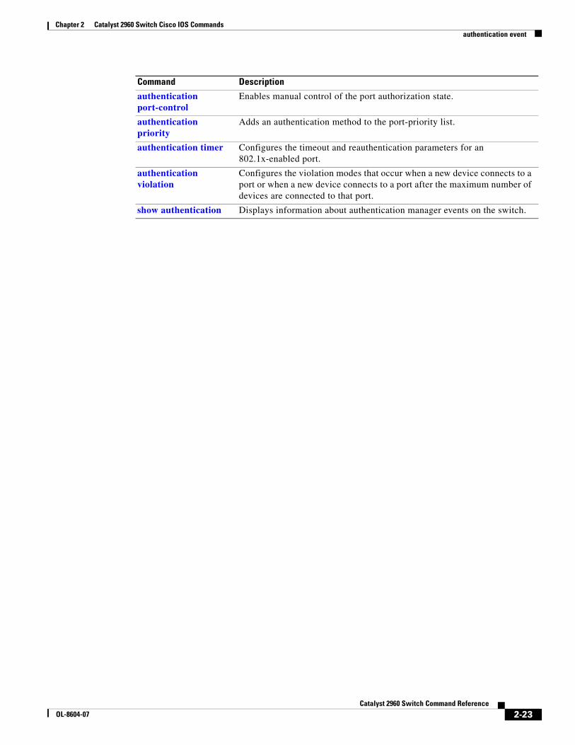
Enables manual control of the port authorization state.
authentication priority
Adds an authentication method to the port-priority list.
authentication timer Configures the timeout and reauthentication parameters for an 802.1x-enabled port.
authentication violation
Configures the violation modes that occur when a new device connects to a port or when a new device connects to a port with the maximum number of devices already connected to that port.
show authentication Displays information about authentication manager events on the switch.
• When the switch moves to the critical-authentication state, new hosts trying to authenticate are moved to the critical-authentication VLAN (or critical VLAN). This applies whether the port is in single-host, multiple-host, multiauth, or MDA mode. Authenticated hosts remain in the authenticated VLAN, and the reauthentication timers are disabled.
• If a client is running Windows XP and the critical port to which the client is connected is in the critical-authentication state, Windows XP might report that the interface is not authenticated.
If the Windows XP client is configured for DHCP and has an IP address from the DHCP server and a critical port receives an EAP-Success message, the DHCP configuration process might not re-initiate.
For no-response events:
• If you enable a guest VLAN on an IEEE 802.1x port, the switch assigns clients to a guest VLAN when it does not receive a response to its Extensible Authentication Protocol over LAN (EAPOL) request/identity frame or when EAPOL packets are not sent by the client.
• The switch maintains the EAPOL packet history. If another EAPOL packet is detected on the port during the lifetime of the link, the guest VLAN feature is disabled. If the port is already in the guest VLAN state, the port returns to the unauthorized state, and authentication restarts. The EAPOL history is cleared.
• If the switch port is moved to the guest VLAN (multi-host mode), multiple non-IEEE 802.1x-capable clients are allowed access. If an IEEE 802.1x-capable client joins the same port on which the guest VLAN is configured, the port is put in the unauthorized state in the RADIUS-configured or user-configured access VLAN, and authentication restarts.
You can configure any active VLAN except a Remote Switched Port Analyzer (RSPAN) VLAN, a primary private VLAN, or a voice VLAN as an IEEE 802.1x guest VLAN. The guest VLAN feature is supported only on access ports. It is not supported on internal VLANs (routed ports) or trunk ports.
• When MAC authentication bypass is enabled on an IEEE 802.1x port, the switch can authorize clients based on the client MAC address if IEEE 802.1x authentication times out while waiting for an EAPOL message exchange. After detecting a client on an IEEE 802.1x port, the switch waits for an Ethernet packet from the client. The switch sends the authentication server a RADIUS-access/request frame with a username and password based on the MAC address.
– If authorization succeeds, the switch grants the client access to the network.
– If authorization fails, the switch assigns the port to the guest VLAN if one is specified.
For more information, see the “Using IEEE 802.1x Authentication with MAC Authentication Bypass” section in the “Configuring IEEE 802.1x Port-Based Authentication” chapter of the software configuration guide.
For authentication-fail events:
• If the supplicant fails authentication, the port is moved to a restricted VLAN, and an EAP success message is sent to the supplicant because it i s not notified of the actual authentication failure.
– If the EAP success message is not sent, the supplicant tries to authenticate every 60 seconds (the default) by sending an EAP-start message.
– Some hosts (for example, devices running Windows XP) cannot implement DHCP until they receive an EAP success message.
The restricted VLAN is supported only in single host mode (the default port mode). When a port is placed in a restricted VLAN, the supplicant's MAC address is added to the MAC address table. Any other MAC address on the port is treated as a security violation.
• You cannot configure an internal VLANs for Layer 3 ports as a restricted VLAN. You cannot specify the same VLAN as a restricted VLAN and as a voice VLAN.
Enable re-authentication with restricted VLANs. If re-authentication is disabled, the ports in the restricted VLANs do not receive re-authentication requests if it is disabled.
To start the re-authentication process, the restricted VLAN must receive a link-down event or an Extensible Authentication Protocol (EAP) logoff event from the port. If a host is connected through a hub:
– The port might not receive a link-down event when the host is disconnected.
– The port might not detect new hosts until the next re-authentication attempt occurs.
When you reconfigure a restricted VLAN as a different type of VLAN, ports in the restricted VLAN are also moved and stay in their currently authorized state.
Examples This example shows how to configure the authentication event fail command:
This example shows how to configure a server-response action:
Switch(config-if)# authentication event server alive action reinitialize
This example shows how to configure a port to send both new and existing hosts to the critical VLAN when the RADIUS server is unavailable. Use this command for ports in multiple authentication (multiauth) mode or if the voice domain of the port is in MDA mode:
Switch(config-if)# authentication event server dead action authorize vlan 10
This example shows how to configure a port to send both new and existing hosts to the critical VLAN when the RADIUS server is unavailable. Use this command for ports in multiple-host or multiauth mode:
Switch(config-if)# authentication event server dead action reinitialize vlan 10
You can verify your settings by entering the show authentication privileged EXEC command.
Related Commands Command Description
authentication control-direction
Configures the port mode as unidirectional or bidirectional.
authentication fallback
Configures a port to use web authentication as a fallback method for clients that do not support IEEE 802.1x authentication
authentication host-mode
Sets the authorization manager mode on a port.
authentication open Enables or disable open access on a port.
authentication order Sets the order of authentication methods used on a port.
Enables manual control of the port authorization state.
authentication priority
Adds an authentication method to the port-priority list.
authentication timer Configures the timeout and reauthentication parameters for an 802.1x-enabled port.
authentication violation
Configures the violation modes that occur when a new device connects to a port or when a new device connects to a port after the maximum number of devices are connected to that port.
show authentication Displays information about authentication manager events on the switch.
authentication fallback Use the authentication fallback interface configuration command to configure a port to use web authentication as a fallback method for clients that do not support IEEE 802.1x authentication. To return to the default setting, use the no form of this command.
authentication fallback name
no authentication fallback name
Syntax Description
Defaults No fallback is enabled.
Command Modes Interface configuration
Command History
Usage Guidelines You must enter the authentication port-control auto interface configuration command before configuring a fallback method.
You can only configure web authentication as a fallback method to 802.1x or MAB, so one or both of these authentication methods should be configured for the fallback to enable.
Examples This example shows how to specify a fallback profile on a port:
Enables manual control of the port authorization state.
authentication priority
Adds an authentication method to the port-priority list.
authentication timer Configures the timeout and reauthentication parameters for an 802.1x-enabled port.
authentication violation
Configures the violation modes that occur when a new device connects to a port or when a new device connects to a port after the maximum number of devices are connected to that port.
show authentication Displays information about authentication manager events on the switch.
no authentication host-mode [multi-auth | multi-domain | multi-host | single-host]
Syntax Description
Defaults Single host mode is enabled.
Command Modes Interface configuration
Command History
Usage Guidelines Single-host mode should be configured if only one data host is connected. Do not connect a voice device to authenticate on a single-host port. Voice device authorization fails if no voice VLAN is configured on the port.
Multi-domain mode should be configured if data host is connected through an IP Phone to the port. Multi-domain mode should be configured if the voice device needs to be authenticated.
Multi-auth mode should be configured to allow up to eight devices behind a hub to obtain secured port access through individual authentication. Only one voice device can be authenticated in this mode if a voice VLAN is configured.
Multi-host mode also offers port access for multiple hosts behind a hub, but multi-host mode gives unrestricted port access to the devices after the first user gets authenticated.
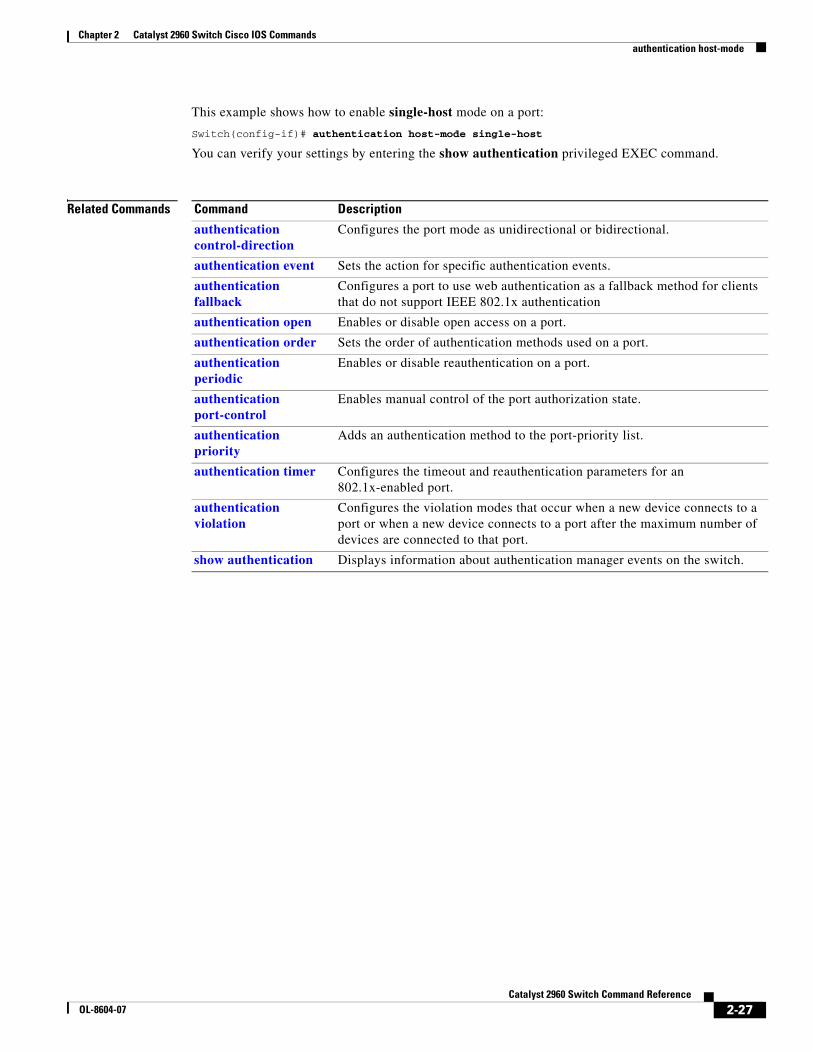
Examples This example shows how to enable multiauth mode on a port:
You can verify your settings by entering the show authentication privileged EXEC command.
Related Commands Command Description
authentication control-direction
Configures the port mode as unidirectional or bidirectional.
authentication event Sets the action for specific authentication events.
authentication fallback
Configures a port to use web authentication as a fallback method for clients that do not support IEEE 802.1x authentication
authentication open Enables or disable open access on a port.
authentication order Sets the order of authentication methods used on a port.
authentication periodic
Enables or disable reauthentication on a port.
authentication port-control
Enables manual control of the port authorization state.
authentication priority
Adds an authentication method to the port-priority list.
authentication timer Configures the timeout and reauthentication parameters for an 802.1x-enabled port.
authentication violation
Configures the violation modes that occur when a new device connects to a port or when a new device connects to a port after the maximum number of devices are connected to that port.
show authentication Displays information about authentication manager events on the switch.
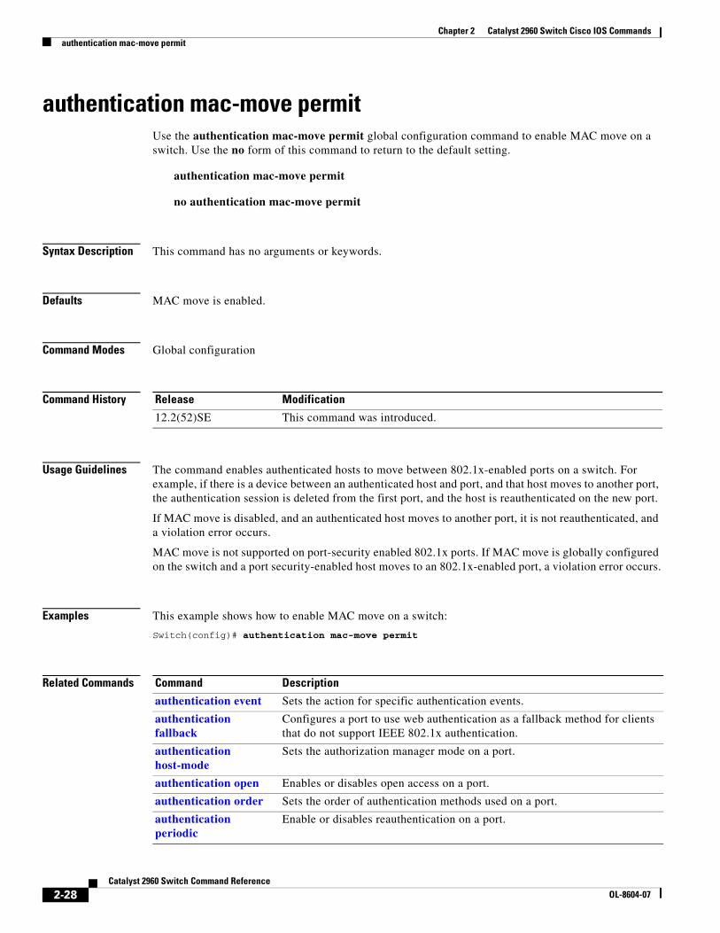
authentication mac-move permit Use the authentication mac-move permit global configuration command to enable MAC move on a switch. Use the no form of this command to return to the default setting.
authentication mac-move permit
no authentication mac-move permit
Syntax Description This command has no arguments or keywords.
Defaults MAC move is enabled.
Command Modes Global configuration
Command History
Usage Guidelines The command enables authenticated hosts to move between 802.1x-enabled ports on a switch. For example, if there is a device between an authenticated host and port, and that host moves to another port, the authentication session is deleted from the first port, and the host is reauthenticated on the new port.
If MAC move is disabled, and an authenticated host moves to another port, it is not reauthenticated, and a violation error occurs.
MAC move is not supported on port-security enabled 802.1x ports. If MAC move is globally configured on the switch and a port security-enabled host moves to an 802.1x-enabled port, a violation error occurs.
Examples This example shows how to enable MAC move on a switch:
Switch(config)# authentication mac-move permit
Related Commands
Release Modification
12.2(52)SE This command was introduced.
Command Description
authentication event Sets the action for specific authentication events.
authentication fallback
Configures a port to use web authentication as a fallback method for clients that do not support IEEE 802.1x authentication.
authentication host-mode
Sets the authorization manager mode on a port.
authentication open Enables or disables open access on a port.
authentication order Sets the order of authentication methods used on a port.
Enables manual control of the port authorization state.
authentication priority
Adds an authentication method to the port-priority list.
authentication timer Configures the timeout and reauthentication parameters for an 802.1x-enabled port.
authentication violation
Configures the violation modes that occur when a new device connects to a port or when a new device connects to a port with the maximum number of devices already connected to that port.
show authentication Displays information about authentication manager events on the switch.
Command Description
2-29Catalyst 2960 Switch Command Reference
OL-8604-07
Chapter 2 Catalyst 2960 Switch Cisco IOS Commandsauthentication open
authentication openUse the authentication open interface configuration command to enable or disable open access on a port. Use the no form of this command to disable open access.
authentication open
no authentication open
Defaults Open access is disabled.
Command Modes Interface configuration
Command History
Usage Guidelines Open authentication must be enabled if a device requires network access before it is authenticated.
A port ACL should be used to restrict host access when open authentication is enabled.
Examples This example shows how to enable open access on a port:
Switch(config-if)# authentication open
This example shows how to set the port to disable open access on a port:
Switch(config-if)# no authentication open
Related Commands
Release Modification
12.2(50)SE This command was introduced.
Command Description
authentication control-direction
Configures the port mode as unidirectional or bidirectional.
authentication event Sets the action for specific authentication events.
authentication fallback
Configures a port to use web authentication as a fallback method for clients that do not support IEEE 802.1x authentication.
authentication host-mode
Sets the authorization manager mode on a port.
authentication order Sets the order of authentication methods used on a port.
authentication periodic
Enables or disables reauthentication on a port.
authentication port-control
Enables manual control of the port authorization state.
authentication priority
Adds an authentication method to the port-priority list.
2-30Catalyst 2960 Switch Command Reference
OL-8604-07
Chapter 2 Catalyst 2960 Switch Cisco IOS Commandsauthentication open
authentication timer Configures the timeout and reauthentication parameters for an 802.1x-enabled port.
authentication violation
Configures the violation modes that occur when a new device connects to a port or when a new device connects to a port after the maximum number of devices are connected to that port.
show authentication Displays information about authentication manager events on the switch.
Command Description
2-31Catalyst 2960 Switch Command Reference
OL-8604-07
Chapter 2 Catalyst 2960 Switch Cisco IOS Commandsauthentication order
authentication orderUse the authentication order interface configuration command to set the order of authentication methods used on a port.
authentication order [dot1x | mab] {webauth}
no authentication order
Syntax Description
Command Default The default authentication order is dot1x followed by mab and webauth.
Command Modes Interface configuration
Command History
Usage Guidelines Ordering sets the order of methods that the switch attempts when trying to authenticate a new device connected to a port. If one method in the list is unsuccessful, the next method is attempted.
Each method can only be entered once. Flexible ordering is only possible between 802.1x and MAB.
Web authentication can be configured as either a standalone method or as the last method in the order after either 802.1x or MAB. Web authentication should be configured only as fallback to dot1x or mab.
Examples This example shows how to add 802.1x as the first authentication method, MAB as the second method, and web authentication as the third method:
Switch(config-if)# authentication order dotx mab webauth
This example shows how to add MAC authentication Bypass (MAB) as the first authentication method and web authentication as the second authentication method:
Switch(config-if)# authentication order mab webauth
You can verify your settings by entering the show authentication privileged EXEC command.
dot1x Add 802.1x to the order of authentication methods.
mab Add MAC authentication bypass (MAB) to the order of authentication methods.
webauth Add web authentication to the order of authentication methods.
Release Modification
12.2(50)SE This command was introduced.
2-32Catalyst 2960 Switch Command Reference
OL-8604-07
Chapter 2 Catalyst 2960 Switch Cisco IOS Commandsauthentication order
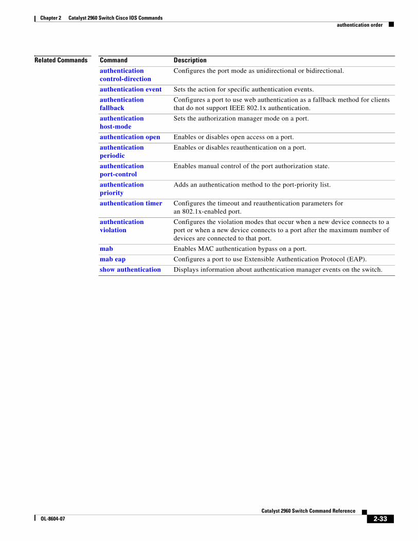
Related Commands Command Description
authentication control-direction
Configures the port mode as unidirectional or bidirectional.
authentication event Sets the action for specific authentication events.
authentication fallback
Configures a port to use web authentication as a fallback method for clients that do not support IEEE 802.1x authentication.
authentication host-mode
Sets the authorization manager mode on a port.
authentication open Enables or disables open access on a port.
authentication periodic
Enables or disables reauthentication on a port.
authentication port-control
Enables manual control of the port authorization state.
authentication priority
Adds an authentication method to the port-priority list.
authentication timer Configures the timeout and reauthentication parameters for an 802.1x-enabled port.
authentication violation
Configures the violation modes that occur when a new device connects to a port or when a new device connects to a port after the maximum number of devices are connected to that port.
mab Enables MAC authentication bypass on a port.
mab eap Configures a port to use Extensible Authentication Protocol (EAP).
show authentication Displays information about authentication manager events on the switch.
authentication periodicUse the authentication periodic interface configuration command to enable or disable reauthentication on a port. Enter the no form of this command to disable reauthentication.
authentication periodic
no authentication periodic
Command Default Reauthentication is disabled.
Command Modes Interface configuration
Command History
Usage Guidelines You configure the amount of time between periodic re-authentication attempts by using the authentication timer reauthentication interface configuration command.
Examples This example shows how to enable periodic reauthentication on a port:
Switch(config-if)# authentication periodic
This example shows how to disable periodic reauthentication on a port:
Switch(config-if)# no authentication periodic
You can verify your settings by entering the show authentication privileged EXEC command.
Related Commands
Release Modification
12.2(50)SE This command was introduced.
Command Description
authentication control-direction
Configures the port mode as unidirectional or bidirectional.
authentication event Sets the action for specific authentication events.
authentication fallback
Configures a port to use web authentication as a fallback method for clients that do not support IEEE 802.1x authentication.
authentication host-mode
Sets the authorization manager mode on a port.
authentication open Enables or disable open access on a port.
authentication order Sets the order of authentication methods used on a port.
authentication port-control
Enables manual control of the port authorization state.
authentication priority
Adds an authentication method to the port-priority list.
authentication timer Configures the timeout and reauthentication parameters for an 802.1x-enabled port.
authentication violation
Configures the violation modes that occur when a new device connects to a port or when a new device connects to a port after the maximum number of devices are connected to that port.
show authentication Displays information about authentication manager events on the switch.
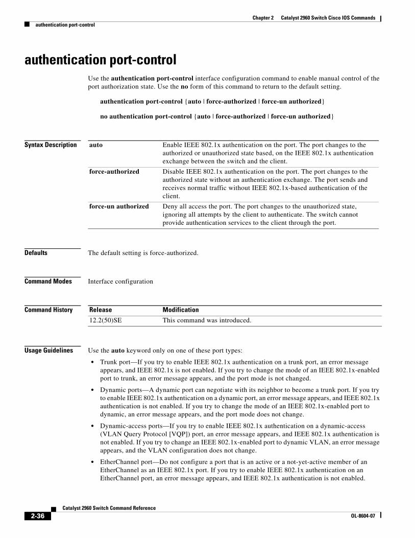
authentication port-controlUse the authentication port-control interface configuration command to enable manual control of the port authorization state. Use the no form of this command to return to the default setting.
no authentication port-control {auto | force-authorized | force-un authorized}
Syntax Description
Defaults The default setting is force-authorized.
Command Modes Interface configuration
Command History
Usage Guidelines Use the auto keyword only on one of these port types:
• Trunk port—If you try to enable IEEE 802.1x authentication on a trunk port, an error message appears, and IEEE 802.1x is not enabled. If you try to change the mode of an IEEE 802.1x-enabled port to trunk, an error message appears, and the port mode is not changed.
• Dynamic ports—A dynamic port can negotiate with its neighbor to become a trunk port. If you try to enable IEEE 802.1x authentication on a dynamic port, an error message appears, and IEEE 802.1x authentication is not enabled. If you try to change the mode of an IEEE 802.1x-enabled port to dynamic, an error message appears, and the port mode does not change.
• Dynamic-access ports—If you try to enable IEEE 802.1x authentication on a dynamic-access (VLAN Query Protocol [VQP]) port, an error message appears, and IEEE 802.1x authentication is not enabled. If you try to change an IEEE 802.1x-enabled port to dynamic VLAN, an error message appears, and the VLAN configuration does not change.
• EtherChannel port—Do not configure a port that is an active or a not-yet-active member of an EtherChannel as an IEEE 802.1x port. If you try to enable IEEE 802.1x authentication on an EtherChannel port, an error message appears, and IEEE 802.1x authentication is not enabled.
auto Enable IEEE 802.1x authentication on the port. The port changes to the authorized or unauthorized state based, on the IEEE 802.1x authentication exchange between the switch and the client.
force-authorized Disable IEEE 802.1x authentication on the port. The port changes to the authorized state without an authentication exchange. The port sends and receives normal traffic without IEEE 802.1x-based authentication of the client.
force-un authorized Deny all access the port. The port changes to the unauthorized state, ignoring all attempts by the client to authenticate. The switch cannot provide authentication services to the client through the port.
• Switched Port Analyzer (SPAN) and Remote SPAN (RSPAN) destination ports—You can enable IEEE 802.1x authentication on a port that is a SPAN or RSPAN destination port. However, IEEE 802.1x authentication is disabled until the port is removed as a SPAN or RSPAN destination. You can enable IEEE 802.1x authentication on a SPAN or RSPAN source port.
To globally disable IEEE 802.1x authentication on the switch, use the no dot1x system-auth-control global configuration command. To disable IEEE 802.1x authentication on a specific port or to return to the default setting, use the no authentication port-control interface configuration command.
Examples This example shows how to set the port state to automatic:
Switch(config-if)# authentication port-control auto
This example shows how to set the port state to the force- authorized state:
You can verify your settings by entering the show authentication privileged EXEC command.
Related Commands Command Description
authentication control-direction
Configures the port mode as unidirectional or bidirectional.
authentication event Sets the action for specific authentication events.
authentication fallback
Configures a port to use web authentication as a fallback method for clients that do not support IEEE 802.1x authentication.
authentication host-mode
Sets the authorization manager mode on a port.
authentication open Enables or disables open access on a port.
authentication order Sets the order of the authentication methods used on a port.
authentication periodic
Enables or disable reauthentication on a port.
authentication priority
Adds an authentication method to the port-priority list.
authentication timer Configures the timeout and reauthentication parameters for an 802.1x-enabled port.
authentication violation
Configures the violation modes that occur when a new device connects to a port or when a new device connects to a port after the maximum number of devices are connected to that port.
show authentication Displays information about authentication manager events on the switch.
authentication priorityUse the authentication priority interface configuration command to add an authentication method to the port-priority list.
auth priority [dot1x | mab] {webauth}
no auth priority [dot1x | mab] {webauth}
Syntax Description
Command Default The default priority is 802.1x authentication, followed by MAC authentication bypass and web authentication.
Command Modes Interface configuration
Command History
Usage Guidelines Ordering sets the order of methods that the switch attempts when trying to authenticate a new device is connected to a port.
When configuring multiple fallback methods on a port, set web authentication (webauth) last.
Assigning priorities to different authentication methods allows a higher-priority method to interrupt an in-progress authentication method with a lower priority.
Note If a client is already authenticated, it might be reauthenticated if an interruption from a higher-priority method occurs.
The default priority of an authentication method is equivalent to its position in execution-list order: 802.1x authentication, MAC authentication bypass, and web authentication. Use the dot1x, mab, and webauth keywords to change this default order.
Examples This example shows how to set 802.1x as the first authentication method and web authentication as the second authentication method:
This example shows how to set MAC authentication Bypass (MAB) as the first authentication method and web authentication as the second authentication method:
Switch(config-if)# authentication priority mab webauth
You can verify your settings by entering the show authentication privileged EXEC command.
Related Commands Command Description
authentication control-direction
Configures the port mode as unidirectional or bidirectional.
authentication event Sets the action for specific authentication events.
authentication fallback
Configures a port to use web authentication as a fallback method for clients that do not support IEEE 802.1x authentication.
authentication host-mode
Sets the authorization manager mode on a port.
authentication open Enables or disables open access on a port.
authentication order Sets the order of authentication methods used on a port.
authentication periodic
Enables or disables reauthentication on a port.
authentication port-control
Enables manual control of the port authorization state.
authentication timer Configures the timeout and reauthentication parameters for an 802.1x-enabled port.
authentication violation
Configures the violation modes that occur when a new device connects to a port or when a new device connects to a port after the maximum number of devices are connected to that port.
mab Enables MAC authentication bypass on a port.
mab eap Configures a port to use Extensible Authentication Protocol (EAP).
show authentication Displays information about authentication manager events on the switch.
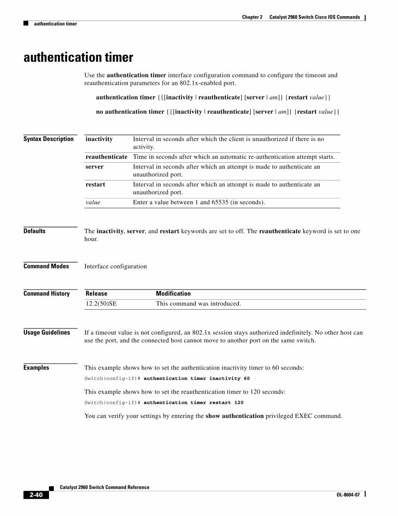
authentication timerUse the authentication timer interface configuration command to configure the timeout and reauthentication parameters for an 802.1x-enabled port.
Defaults The inactivity, server, and restart keywords are set to off. The reauthenticate keyword is set to one hour.
Command Modes Interface configuration
Command History
Usage Guidelines If a timeout value is not configured, an 802.1x session stays authorized indefinitely. No other host can use the port, and the connected host cannot move to another port on the same switch.
Examples This example shows how to set the authentication inactivity timer to 60 seconds:
Configures the port mode as unidirectional or bidirectional.
authentication event Sets the action for specific authentication events.
authentication fallback
Configures a port to use web authentication as a fallback method for clients that do not support IEEE 802.1x authentication.
authentication host-mode
Sets the authorization manager mode on a port.
authentication open Enables or disables open access on a port.
authentication order Sets the order of authentication methods used on a port.
authentication periodic
Enables or disables reauthentication on a port.
authentication port-control
Enables manual control of the port authorization state.
authentication priority
Adds an authentication method to the port-priority list.
authentication violation
Configures the violation modes that occur when a new device connects to a port or when a new device connects to a port after the maximum number of devices are connected to that port.
show authentication Displays information about authentication manager events on the switch.
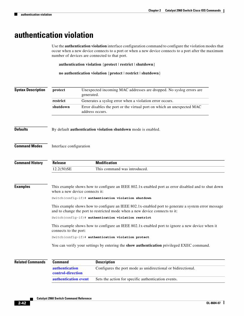
authentication violationUse the authentication violation interface configuration command to configure the violation modes that occur when a new device connects to a port or when a new device connects to a port after the maximum number of devices are connected to that port.
This example shows how to configure an IEEE 802.1x-enabled port to generate a system error message and to change the port to restricted mode when a new device connects to it:
Configures a port to use web authentication as a fallback method for clients that do not support IEEE 802.1x authentication.
authentication host-mode
Sets the authorization manager mode on a port.
authentication open Enables or disables open access on a port.
authentication order Sets the order of authentication methods used on a port.
authentication periodic
Enables or disables reauthentication on a port.
authentication port-control
Enables manual control of the port authorization state.
authentication priority
Adds an authentication method to the port-priority list.
authentication timer Configures the timeout and reauthentication parameters for an 802.1x-enabled port.
show authentication Displays information about authentication manager events on the switch.
Command Description
2-43Catalyst 2960 Switch Command Reference
OL-8604-07
Chapter 2 Catalyst 2960 Switch Cisco IOS Commandsauto qos voip
auto qos voip Use the auto qos voip interface configuration command to automatically configure quality of service (QoS) for voice over IP (VoIP) within a QoS domain. Use the no form of this command to return to the default setting.
auto qos voip {cisco-phone | cisco-softphone | trust}
no auto qos voip [cisco-phone | cisco-softphone | trust]
Note To use this command, the switch must be running the LAN Base image.
Syntax Description
Defaults Auto-QoS is disabled on the port.
When auto-QoS is enabled, it uses the ingress packet label to categorize traffic, to assign packet labels, and to configure the ingress and egress queues as shown in Table 2-1.
cisco-phone Identify this port as connected to a Cisco IP Phone, and automatically configure QoS for VoIP. The QoS labels of incoming packets are trusted only when the telephone is detected.
cisco-softphone Identify this port as connected to a device running the Cisco SoftPhone, and automatically configure QoS for VoIP.
trust Identify this port as connected to a trusted switch or router, and automatically configure QoS for VoIP. The QoS labels of incoming packets are trusted. For nonrouted ports, the CoS value of the incoming packet is trusted.
Table 2-1 Traffic Types, Packet Labels, and Queues
Chapter 2 Catalyst 2960 Switch Cisco IOS Commandsauto qos voip
Table 2-2 shows the generated auto-QoS configuration for the ingress queues.
Table 2-3 shows the generated auto-QoS configuration for the egress queues.
Command Modes Interface configuration
Command History
Usage Guidelines Use this command to configure the QoS appropriate for VoIP traffic within the QoS domain. The QoS domain includes the switch, the interior of the network, and edge devices that can classify incoming traffic for QoS.
Auto-QoS configures the switch for VoIP with Cisco IP Phones on switch and routed ports and for VoIP with devices running the Cisco SoftPhone application. These releases support only Cisco IP SoftPhone Version 1.3(3) or later. Connected devices must use Cisco Call Manager Version 4 or later.
The show auto qos command output shows the service policy information for the Cisco IP phone.
To take advantage of the auto-QoS defaults, you should enable auto-QoS before you configure other QoS commands. You can fine-tune the auto-QoS configuration after you enable auto-QoS.
Note The switch applies the auto-QoS-generated commands as if the commands were entered from the command-line interface (CLI). An existing user configuration can cause the application of the generated commands to fail or to be overridden by the generated commands. These actions occur without warning. If all the generated commands are successfully applied, any user-entered configuration that was not
Table 2-2 Auto-QoS Configuration for the Ingress Queues
Ingress Queue Queue Number CoS-to-Queue MapQueue Weight (Bandwidth)
Chapter 2 Catalyst 2960 Switch Cisco IOS Commandsauto qos voip
overridden remains in the running configuration. Any user-entered configuration that was overridden can be retrieved by reloading the switch without saving the current configuration to memory. If the generated commands fail to be applied, the previous running configuration is restored.
If this is the first port on which you have enabled auto-QoS, the auto-QoS-generated global configuration commands are executed followed by the interface configuration commands. If you enable auto-QoS on another port, only the auto-QoS-generated interface configuration commands for that port are executed.
When you enable the auto-QoS feature on the first port, these automatic actions occur:
• QoS is globally enabled (mls qos global configuration command), and other global configuration commands are added.
If the switch port was configured by using the auto qos voip cisco-phone interface configuration command in Cisco IOS Release 12.2(37)SE or earlier, the auto-QoS generated commands new to Cisco IOS Release 12.2(40)SE are not applied to the port. To have these commands automatically applied, you must remove and then reapply the configuration to the port.
• When you enter the auto qos voip cisco-softphone interface configuration command on a port at the edge of the network that is connected to a device running the Cisco SoftPhone, the switch uses policing to decide whether a packet is in or out of profile and to specify the action on the packet. If the packet does not have a DSCP value of 24, 26, or 46 or is out of profile, the switch changes the DSCP value to 0. The switch configures ingress and egress queues on the port according to the settings in Table 2-2 and Table 2-3.
• When you enter the auto qos voip trust interface configuration command on a port connected to the interior of the network, the switch trusts the CoS value for nonrouted ports in ingress packets (the assumption is that traffic has already been classified by other edge devices). The switch configures the ingress and egress queues on the port according to the settings in Table 2-2 and Table 2-3.
You can enable auto-QoS on static, dynamic-access, and voice VLAN access, and trunk ports. When enabling auto-QoS with a Cisco IP Phone on a routed port, you must assign a static IP address to the IP phone.
Note When a device running Cisco SoftPhone is connected to a switch or routed port, the switch supports only one Cisco SoftPhone application per port.
After auto-QoS is enabled, do not modify a policy map or aggregate policer that includes AutoQoS in its name. If you need to modify the policy map or aggregate policer, make a copy of it, and change the copied policy map or policer. To use the new policy map instead of the generated one, remove the generated policy map from the interface, and apply the new policy map.
To display the QoS configuration that is automatically generated when auto-QoS is enabled, enable debugging before you enable auto-QoS. Use the debug auto qos privileged EXEC command to enable auto-QoS debugging. For more information, see the debug auto qos command.
To disable auto-QoS on a port, use the no auto qos voip interface configuration command. Only the auto-QoS-generated interface configuration commands for this port are removed. If this is the last port on which auto-QoS is enabled and you enter the no auto qos voip command, auto-QoS is considered disabled even though the auto-QoS-generated global configuration commands remain (to avoid disrupting traffic on other ports affected by the global configuration). You can use the no mls qos global configuration command to disable the auto-QoS-generated global configuration commands. With QoS disabled, there is no concept of trusted or untrusted ports because the packets are not modified (the CoS, DSCP, and IP precedence values in the packet are not changed). Traffic is switched in pass-through mode (packets are switched without any rewrites and classified as best effort without any policing).
2-46Catalyst 2960 Switch Command Reference
OL-8604-07
Chapter 2 Catalyst 2960 Switch Cisco IOS Commandsauto qos voip
Examples This example shows how to enable auto-QoS and to trust the QoS labels received in incoming packets when the switch or router connected to the port is a trusted device:
Switch(config)# interface gigabitethernet0/1Switch(config-if)# auto qos voip trust
You can verify your settings by entering the show auto qos interface interface-id privileged EXEC command.
Related Commands Command Description
debug auto qos Enables debugging of the auto-QoS feature.
mls qos cos Defines the default CoS value of a port or assigns the default CoS to all incoming packets on the port.
boot config-fileUse the boot config-file global configuration command to specify the filename that Cisco IOS uses to read and write a nonvolatile copy of the system configuration. Use the no form of this command to return to the default setting.
boot config-file flash:/file-url
no boot config-file
Syntax Description
Defaults The default configuration file is flash:config.text.
Command Modes Global configuration
Command History
Usage Guidelines Filenames and directory names are case sensitive.
This command changes the setting of the CONFIG_FILE environment variable. For more information, see Appendix A, “Catalyst 2960 Switch Bootloader Commands.”
Related Commands
flash:/file-url The path (directory) and name of the configuration file.
Release Modification
12.2(25)FX This command was introduced.
Command Description
show boot Displays the settings of the boot environment variables.
boot enable-breakUse the boot enable-break global configuration command to enable interrupting the automatic boot process. Use the no form of this command to return to the default setting.
boot enable-break
no boot enable-break
Syntax Description This command has no arguments or keywords.
Defaults Disabled. The automatic boot process cannot be interrupted by pressing the Break key on the console.
Command Modes Global configuration
Command History
Usage Guidelines When you enter this command, you can interrupt the automatic boot process by pressing the Break key on the console after the flash file system is initialized.
Note Despite the setting of this command, you can interrupt the automatic boot process at any time by pressing the MODE button on the switch front panel.
This command changes the setting of the ENABLE_BREAK environment variable. For more information, see Appendix A, “Catalyst 2960 Switch Bootloader Commands.”
Related Commands
Release Modification
12.2(25)FX This command was introduced.
Command Description
show boot Displays the settings of the boot environment variables.
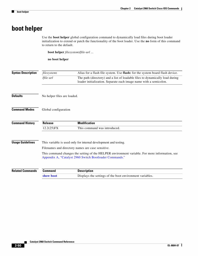
boot helperUse the boot helper global configuration command to dynamically load files during boot loader initialization to extend or patch the functionality of the boot loader. Use the no form of this command to return to the default.
boot helper filesystem:/file-url ...
no boot helper
Syntax Description
Defaults No helper files are loaded.
Command Modes Global configuration
Command History
Usage Guidelines This variable is used only for internal development and testing.
Filenames and directory names are case sensitive.
This command changes the setting of the HELPER environment variable. For more information, see Appendix A, “Catalyst 2960 Switch Bootloader Commands.”
Related Commands
filesystem: Alias for a flash file system. Use flash: for the system board flash device.
/file-url The path (directory) and a list of loadable files to dynamically load during loader initialization. Separate each image name with a semicolon.
Release Modification
12.2(25)FX This command was introduced.
Command Description
show boot Displays the settings of the boot environment variables.
boot helper-config-fileUse the boot helper-config-file global configuration command to specify the name of the configuration file to be used by the Cisco IOS helper image. If this is not set, the file specified by the CONFIG_FILE environment variable is used by all versions of Cisco IOS that are loaded. Use the no form of this command to return to the default setting.
boot helper-config-file filesystem:/file-url
no boot helper-config file
Syntax Description
Defaults No helper configuration file is specified.
Command Modes Global configuration
Command History
Usage Guidelines This variable is used only for internal development and testing.
Filenames and directory names are case sensitive.
This command changes the setting of the HELPER_CONFIG_FILE environment variable. For more information, see Appendix A, “Catalyst 2960 Switch Bootloader Commands.”
Related Commands
filesystem: Alias for a flash file system. Use flash: for the system board flash device.
/file-url The path (directory) and helper configuration file to load.
Release Modification
12.2(25)FX This command was introduced.
Command Description
show boot Displays the settings of the boot environment variables.
boot manualUse the boot manual global configuration command to enable manually booting the switch during the next boot cycle. Use the no form of this command to return to the default setting.
boot manual
no boot manual
Syntax Description This command has no arguments or keywords.
Defaults Manual booting is disabled.
Command Modes Global configuration
Command History
Usage Guidelines The next time you reboot the system, the switch is in boot loader mode, which is shown by the switch: prompt. To boot up the system, use the boot boot loader command, and specify the name of the bootable image.
This command changes the setting of the MANUAL_BOOT environment variable. For more information, see Appendix A, “Catalyst 2960 Switch Bootloader Commands.”
Related Commands
Release Modification
12.2(25)FX This command was introduced.
Command Description
show boot Displays the settings of the boot environment variables.
boot private-config-fileUse the boot private-config-file global configuration command to specify the filename that Cisco IOS uses to read and write a nonvolatile copy of the private configuration. Use the no form of this command to return to the default setting.
boot private-config-file filename
no boot private-config-file
Syntax Description
Defaults The default configuration file is private-config.
Command Modes Global configuration
Command History
Usage Guidelines Filenames are case sensitive.
Examples This example shows how to specify the name of the private configuration file to be pconfig:
Switch(config)# boot private-config-file pconfig
Related Commands
filename The name of the private configuration file.
Release Modification
12.2(25)FX This command was introduced.
Command Description
show boot Displays the settings of the boot environment variables.
2-53Catalyst 2960 Switch Command Reference
OL-8604-07
Chapter 2 Catalyst 2960 Switch Cisco IOS Commandsboot system
boot systemUse the boot system global configuration command to specify the Cisco IOS image to load during the next boot cycle. Use the no form of this command to return to the default setting.
boot system filesystem:/file-url ...
no boot system
Syntax Description
Defaults The switch attempts to automatically boot up the system by using information in the BOOT environment variable. If this variable is not set, the switch attempts to load and execute the first executable image it can by performing a recursive, depth-first search throughout the flash file system. In a depth-first search of a directory, each encountered subdirectory is completely searched before continuing the search in the original directory.
Command Modes Global configuration
Command History
Usage Guidelines Filenames and directory names are case sensitive.
If you are using the archive download-sw privileged EXEC command to maintain system images, you never need to use the boot system command. The boot system command is automatically manipulated to load the downloaded image.
This command changes the setting of the BOOT environment variable. For more information, see Appendix A, “Catalyst 2960 Switch Bootloader Commands.”
Related Commands
filesystem: Alias for a flash file system. Use flash: for the system board flash device.
/file-url The path (directory) and name of a bootable image. Separate image names with a semicolon.
Release Modification
12.2(25)FX This command was introduced.
Command Description
show boot Displays the settings of the boot environment variables.
channel-groupUse the channel-group interface configuration command to assign an Ethernet port to an EtherChannel group, to enable an EtherChannel mode, or both. Use the no form of this command to remove an Ethernet port from an EtherChannel group.
On mode: channel-group channel-group-number mode on
Syntax Description channel-group-number Specify the channel group number. The range is 1 to 6.
mode Specify the EtherChannel mode.
active Unconditionally enable Link Aggregation Control Protocol (LACP).
Active mode places a port into a negotiating state in which the port initiates negotiations with other ports by sending LACP packets. A channel is formed with another port group in either the active or passive mode.
auto Enable the Port Aggregation Protocol (PAgP) only if a PAgP device is detected.
Auto mode places a port into a passive negotiating state in which the port responds to PAgP packets it receives but does not start PAgP packet negotiation. A channel is formed only with another port group in desirable mode. When auto is enabled, silent operation is the default.
desirable Unconditionally enable PAgP.
Desirable mode places a port into an active negotiating state in which the port starts negotiations with other ports by sending PAgP packets. An EtherChannel is formed with another port group that is in the desirable or auto mode. When desirable is enabled, silent operation is the default.
non-silent (Optional) Use in PAgP mode with the auto or desirable keyword when traffic is expected from the other device.
on Enable on mode.
In on mode, a usable EtherChannel exists only when both connected port groups are in the on mode.
passive Enable LACP only if a LACP device is detected.
Passive mode places a port into a negotiating state in which the port responds to received LACP packets but does not initiate LACP packet negotiation. A channel is formed only with another port group in active mode.
Usage Guidelines For Layer 2 EtherChannels, you do not have to create a port-channel interface first by using the interface port-channel global configuration command before assigning a physical port to a channel group. Instead, you can use the channel-group interface configuration command. It automatically creates the port-channel interface when the channel group gets its first physical port if the logical interface is not already created. If you create the port-channel interface first, the channel-group-number can be the same as the port-channel-number, or you can use a new number. If you use a new number, the channel-group command dynamically creates a new port channel.
After you configure an EtherChannel, configuration changes that you make on the port-channel interface apply to all the physical ports assigned to the port-channel interface. Configuration changes applied to the physical port affect only the port where you apply the configuration. To change the parameters of all ports in an EtherChannel, apply configuration commands to the port-channel interface, for example, spanning-tree commands or commands to configure a Layer 2 EtherChannel as a trunk.
If you do not specify non-silent with the auto or desirable mode, silent is assumed. The silent mode is used when the switch is connected to a device that is not PAgP-capable and seldom, if ever, sends packets. A example of a silent partner is a file server or a packet analyzer that is not generating traffic. In this case, running PAgP on a physical port prevents that port from ever becoming operational. However, it allows PAgP to operate, to attach the port to a channel group, and to use the port for transmission. Both ends of the link cannot be set to silent.
In the on mode, an EtherChannel exists only when a port group in the on mode is connected to another port group in the on mode.
Caution You should use care when using the on mode. This is a manual configuration, and ports on both ends of the EtherChannel must have the same configuration. If the group is misconfigured, packet loss or spanning-tree loops can occur.
Do not configure an EtherChannel in both the PAgP and LACP modes. EtherChannel groups running PAgP and LACP can coexist on the same switch. Individual EtherChannel groups can run either PAgP or LACP, but they cannot interoperate.
If you set the protocol by using the channel-protocol interface configuration command, the setting is not overridden by the channel-group interface configuration command.
Do not configure a port that is an active or a not-yet-active member of an EtherChannel as an IEEE 802.1x port. If you try to enable IEEE 802.1x authentication on an EtherChannel port, an error message appears, and IEEE 802.1x authentication is not enabled.
Do not configure a secure port as part of an EtherChannel or an EtherChannel port as a secure port.
channel-protocol Use the channel-protocol interface configuration command to restrict the protocol used on a port to manage channeling. Use the no form of this command to return to the default setting.
channel-protocol {lacp | pagp}
no channel-protocol
Syntax Description
Defaults No protocol is assigned to the EtherChannel.
Command Modes Interface configuration
Command History
Usage Guidelines Use the channel-protocol command only to restrict a channel to LACP or PAgP. If you set the protocol by using the channel-protocol command, the setting is not overridden by the channel-group interface configuration command.
You must use the channel-group interface configuration command to configure the EtherChannel parameters. The channel-group command also can set the mode for the EtherChannel.
You cannot enable both the PAgP and LACP modes on an EtherChannel group.
PAgP and LACP are not compatible; both ends of a channel must use the same protocol.
Examples This example shows how to specify LACP as the protocol that manages the EtherChannel:
Switch(config-if)# channel-protocol lacp
You can verify your settings by entering the show etherchannel [channel-group-number] protocol privileged EXEC command.
Related Commands
lacp Configure an EtherChannel with the Link Aggregation Control Protocol (LACP).
pagp Configure an EtherChannel with the Port Aggregation Protocol (PAgP).
Release Modification
12.2(25)FX This command was introduced.
Command Description
channel-group Assigns an Ethernet port to an EtherChannel group.
show etherchannel protocol Displays protocol information the EtherChannel.
cisp enableUse the cisp enable global configuration command to enable Client Information Signalling Protocol (CISP) on a switch so that it acts as an authenticator to a supplicant switch.
cisp enable
no cisp enable
Syntax Description
Defaults There is no default setting.
Command Modes Global configuration
Command History
Usage Guidelines The link between the authenticator and supplicant switch is a trunk. When you enable VTP on both switches, the VTP domain name must be the same, and the VTP mode must be server.
When you configure VTP mode, to avoid the MD5 checksum mismatch error, verify that:
• VLANs are not configured on two different.switches, which can be caused by two VTP servers in the same domain.
• Both switches have the different configuration revision numbers.
Examples This example shows how to enable CISP:
switch(config)# cisp enable
Related Commands
cisp enable Enable CISP.
Release Modification
12.2(50)SE This command was introduced.
Command Description
dot1x credentials (global configuration) profile
Configures a profile on a supplicant switch.
show cisp Displays CISP information for a specified interface.
classUse the class policy-map configuration command to define a traffic classification match criteria (through the police, set, and trust policy-map class configuration commands) for the specified class-map name. Use the no form of this command to delete an existing class map.
class class-map-name
no class class-map-name
Note To use this command, the switch must be running the LAN Base image.
Syntax Description
Defaults No policy map class-maps are defined.
Command Modes Policy-map configuration
Command History
Usage Guidelines Before using the class command, you must use the policy-map global configuration command to identify the policy map and to enter policy-map configuration mode. After specifying a policy map, you can configure a policy for new classes or modify a policy for any existing classes in that policy map. You attach the policy map to a port by using the service-policy interface configuration command.
After entering the class command, you enter policy-map class configuration mode, and these configuration commands are available:
• exit: exits policy-map class configuration mode and returns to policy-map configuration mode.
• no: returns a command to its default setting.
• police: defines a policer or aggregate policer for the classified traffic. The policer specifies the bandwidth limitations and the action to take when the limits are exceeded. For more information, see the police and police aggregate policy-map class commands.
• set: specifies a value to be assigned to the classified traffic. For more information, see the set command.
• trust: defines a trust state for traffic classified with the class or the class-map command. For more information, see the trust command.
To return to policy-map configuration mode, use the exit command. To return to privileged EXEC mode, use the end command.
The class command performs the same function as the class-map global configuration command. Use the class command when a new classification, which is not shared with any other ports, is needed. Use the class-map command when the map is shared among many ports.
Examples This example shows how to create a policy map called policy1. When attached to the ingress direction, it matches all the incoming traffic defined in class1, sets the IP Differentiated Services Code Point (DSCP) to 10, and polices the traffic at an average rate of 1 Mb/s and bursts at 20 KB. Traffic exceeding the profile is marked down to a DSCP value gotten from the policed-DSCP map and then sent.
Switch(config)# policy-map policy1Switch(config-pmap)# class class1Switch(config-pmap-c)# set dscp 10Switch(config-pmap-c)# police 1000000 20000 exceed-action policed-dscp-transmitSwitch(config-pmap-c)# exit
You can verify your settings by entering the show policy-map privileged EXEC command.
Related Commands Command Description
class-map Creates a class map to be used for matching packets to the class whose name you specify.
police Defines a policer for classified traffic.
policy-map Creates or modifies a policy map that can be attached to multiple ports to specify a service policy.
set Classifies IP traffic by setting a DSCP or IP-precedence value in the packet.
show policy-map Displays quality of service (QoS) policy maps.
trust Defines a trust state for the traffic classified through the class policy-map configuration command or the class-map global configuration command.
class-mapUse the class-map global configuration command to create a class map to be used for matching packets to the class name you specify and to enter class-map configuration mode. Use the no form of this command to delete an existing class map and to return to global configuration mode.
class-map [match-all | match-any] class-map-name
no class-map [match-all | match-any] class-map-name
Note To use this command, the switch must be running the LAN Base image.
Syntax Description
Defaults No class maps are defined.
If neither the match-all or match-any keyword is specified, the default is match-all.
Command Modes Global configuration
Command History
Usage Guidelines Use this command to specify the name of the class for which you want to create or modify class-map match criteria and to enter class-map configuration mode.
The class-map command and its subcommands are used to define packet classification, marking, and aggregate policing as part of a globally named service policy applied on a per-port basis.
After you are in quality of service (QoS) class-map configuration mode, these configuration commands are available:
• description: describes the class map (up to 200 characters). The show class-map privileged EXEC command displays the description and the name of the class-map.
• exit: exits from QoS class-map configuration mode.
• match: configures classification criteria. For more information, see the match (class-map configuration) command.
• no: removes a match statement from a class map.
match-all (Optional) Perform a logical-AND of all matching statements under this class map. All criteria in the class map must be matched.
match-any (Optional) Perform a logical-OR of the matching statements under this class map. One or more criteria must be matched.
• rename: renames the current class map. If you rename a class map with a name that is already used, the message A class-map with this name already exists appears.
To define packet classification on a physical-port basis, only one match command per class map is supported. In this situation, the match-all and match-any keywords are equivalent.
Only one access control list (ACL) can be configured in a class map. The ACL can have multiple access control entries (ACEs).
Examples This example shows how to configure the class map called class1 with one match criterion, which is an access list called 103:
Switch(config)# access-list 103 permit ip any any dscp 10Switch(config)# class-map class1Switch(config-cmap)# match access-group 103Switch(config-cmap)# exit
This example shows how to delete the class map class1:
Switch(config)# no class-map class1
You can verify your settings by entering the show class-map privileged EXEC command.
Related Commands Command Description
class Defines a traffic classification match criteria (through the police, set, and trust policy-map class configuration commands) for the specified class-map name.
match (class-map configuration)
Defines the match criteria to classify traffic.
policy-map Creates or modifies a policy map that can be attached to multiple ports to specify a service policy.
clear dot1xUse the clear dot1x privileged EXEC command to clear IEEE 802.1x information for the switch or for the specified port.
clear dot1x {all | interface interface-id}
Syntax Description
Defaults No default is defined.
Command Modes Privileged EXEC
Command History
Usage Guidelines You can clear all the information by using the clear dot1x all command, or you can clear only the information for the specified interface by using the clear dot1x interface interface-id command.
Examples This example shows how to clear all IEEE 8021.x information:
Switch# clear dot1x all
This example shows how to clear IEEE 8021.x information for the specified interface:
clear eap sessionsUse the clear eap sessions privileged EXEC command to clear Extensible Authentication Protocol (EAP) session information for the switch or for the specified port.
clear eap sessions [credentials name [interface interface-id] | interface interface-id | method name | transport name] [credentials name | interface interface-id | transport name] ...
Syntax Description
Defaults No default is defined.
Command Modes Privileged EXEC
Command History
Usage Guidelines You can clear all counters by using the clear eap sessions command, or you can clear only the specific information by using the keywords.
Examples This example shows how to clear all EAP information:
Switch# clear eap
This example shows how to clear EAP-session credential information for the specified profile:
Switch# clear eap sessions credential type1
You can verify that the information was deleted by entering the show dot1x privileged EXEC command.
Related Commands
credentials name Clear EAP credential information for the specified profile.
interface interface-id Clear EAP information for the specified interface.
method name Clear EAP information for the specified method.
transport name Clear EAP transport information for the specified lower level.
Release Modification
12.2(25)SEE This command was introduced.
Command Description
show eap Displays EAP registration and session information for the switch or for the specified port
Usage Guidelines You can re-enable a port by using the shutdown and no shutdown interface configuration commands, or you can clear error disable for VLANs by using the clear errdisable interface command.
Examples This example shows how to re-enable all VLANs that were error-disabled on port 2.
clear ip arp inspection statisticsUse the clear ip arp inspection statistics privileged EXEC command to clear the dynamic Address Resolution Protocol (ARP) inspection statistics.
clear ip arp inspection statistics [vlan vlan-range]
Syntax Description
Defaults No default is defined.
Command Modes Privileged EXEC
Command History
Examples This example shows how to clear the statistics for VLAN 1:
Switch# clear ip arp inspection statistics vlan 1
You can verify that the statistics were deleted by entering the show ip arp inspection statistics vlan 1 privileged EXEC command.
Related Commands
vlan vlan-range (Optional) Clear statistics for the specified VLAN or VLANs.
You can specify a single VLAN identified by VLAN ID number, a range of VLANs separated by a hyphen, or a series of VLANs separated by a comma. The range is 1 to 4094.
Release Modification
12.2(50)SE This command was introduced.
Command Description
show inventory statistics Displays statistics for forwarded, dropped, MAC validation failure, and IP validation failure packets for all VLANs or the specified VLAN.
clear ip dhcp snooping Use the clear ip dhcp snooping privileged EXEC command to clear the DHCP snooping binding database, the DHCP snooping binding database agent statistics, or the DHCP snooping statistics counters.
Note To use this command, the switch must be running the LAN Base image.
Syntax Description
Defaults No default is defined.
Command Modes Privileged EXEC
Command History
Usage Guidelines When you enter the clear ip dhcp snooping database statistics command, the switch does not update the entries in the binding database and in the binding file before clearing the statistics.
Examples This example shows how to clear the DHCP snooping binding database agent statistics:
Switch# clear ip dhcp snooping database statistics
You can verify that the statistics were cleared by entering the show ip dhcp snooping database privileged EXEC command.
This example shows how to clear the DHCP snooping statistics counters:
Switch# clear ip dhcp snooping statistics
binding Clear the DHCP snooping binding database.
* Clear all automatic bindings.
ip-address Clear the binding entry IP address.
interface interface-id Clear the binding input interface.
vlan vlan-id Clear the binding entry VLAN.
database statistics Clear the DHCP snooping binding database agent statistics.
statistics Clear the DHCP snooping statistics counter.
Release Modification
12.2(25)FX This command was introduced.
12.2(37)SE The statistics keyword was introduced.
12.2(44)SE The *, ip-address, interface interface-id, and vlan vlan-id keywords were introduced.
Usage Guidelines You can clear all counters by using the clear lacp counters command, or you can clear only the counters for the specified channel group by using the clear lacp channel-group-number counters command.
Examples This example shows how to clear all channel-group information:
Switch# clear lacp counters
This example shows how to clear LACP traffic counters for group 4:
Switch# clear lacp 4 counters
You can verify that the information was deleted by entering the show lacp counters or the show lacp 4 counters privileged EXEC command.
Related Commands
channel-group-number (Optional) Channel group number. The range is 1 to 6.
counters Clear traffic counters.
Release Modification
12.2(25)FX This command was introduced.
Command Description
show lacp Displays LACP channel-group information.
2-71Catalyst 2960 Switch Command Reference
OL-8604-07
Chapter 2 Catalyst 2960 Switch Cisco IOS Commandsclear mac address-table
clear mac address-tableUse the clear mac address-table privileged EXEC command to delete from the MAC address table a specific dynamic address, all dynamic addresses on a particular interface, or all dynamic addresses on a particular VLAN. This command also clears the MAC address notification global counters.
clear mac address-table move updateUse the clear mac address-table move update privileged EXEC command to clear the mac address-table-move update-related counters.
clear mac address-table move update
Syntax Description This command has no arguments or keywords.
Defaults No default is defined.
Command Modes Privileged EXEC
Command History
Examples This example shows how to clear the mac address-table move update related counters.
Switch# clear mac address-table move update
You can verify that the information was cleared by entering the show mac address-table move update privileged EXEC command.
Related Commands
Release Modification
12.2(25)SED This command was introduced.
Command Description
mac address-table move update {receive | transmit}
Configures MAC address-table move update on the switch.
show mac address-table move update Displays the MAC address-table move update information on the switch.
clear nmsp statisticsUse the clear nmsp statistics privileged EXEC command to clear the Network Mobility Services Protocol (NMSP) statistics. This command is available only when your switch is running the cryptographic (encrypted) software image.
clear nmsp statistics
Note To use this command, the switch must be running the LAN Base image.
Syntax Description This command has no arguments or keywords.
Defaults No default is defined.
Command Modes Privileged EXEC
Command History
Examples This example shows how to clear NMSP statistics:
Switch# clear nmsp statistics
You can verify that information was deleted by entering the show nmsp statistics privileged EXEC command.
Usage Guidelines You can clear all counters by using the clear pagp counters command, or you can clear only the counters for the specified channel group by using the clear pagp channel-group-number counters command.
Examples This example shows how to clear all channel-group information:
Switch# clear pagp counters
This example shows how to clear PAgP traffic counters for group 10:
Switch# clear pagp 10 counters
You can verify that information was deleted by entering the show pagp privileged EXEC command.
Related Commands
channel-group-number (Optional) Channel group number. The range is 1 to 6.
counters Clear traffic counters.
Release Modification
12.2(25)FX This command was introduced.
Command Description
show pagp Displays PAgP channel-group information.
clear port-securityUse the clear port-security privileged EXEC command to delete from the MAC address table all secure addresses or all secure addresses of a specific type (configured, dynamic, or sticky) on the switch or on an interface.
Usage Guidelines If the interface-id is not specified, spanning-tree counters are cleared for all interfaces.
Examples This example shows how to clear spanning-tree counters for all interfaces:
Switch# clear spanning-tree counters
Related Commands
interface interface-id (Optional) Clear all spanning-tree counters on the specified interface. Valid interfaces include physical ports, VLANs, and port channels. The VLAN range is 1 to 4094. The port-channel range is 1 to 6.
Release Modification
12.2(25)FX This command was introduced.
Command Description
show spanning-tree Displays spanning-tree state information.
clear spanning-tree detected-protocols Use the clear spanning-tree detected-protocols privileged EXEC command to restart the protocol migration process (force the renegotiation with neighboring switches) on all interfaces or on the specified interface.
Usage Guidelines A switch running the rapid per-VLAN spanning-tree plus (rapid-PVST+) protocol or the Multiple Spanning Tree Protocol (MSTP) supports a built-in protocol migration mechanism that enables it to interoperate with legacy IEEE 802.1D switches. If a rapid-PVST+ switch or an MSTP switch receives a legacy IEEE 802.1D configuration bridge protocol data unit (BPDU) with the protocol version set to 0, it sends only IEEE 802.1D BPDUs on that port. A multiple spanning-tree (MST) switch can also detect that a port is at the boundary of a region when it receives a legacy BPDU, an MST BPDU (Version 3) associated with a different region, or a rapid spanning-tree (RST) BPDU (Version 2).
However, the switch does not automatically revert to the rapid-PVST+ or the MSTP mode if it no longer receives IEEE 802.1D BPDUs because it cannot learn whether the legacy switch has been removed from the link unless the legacy switch is the designated switch. Use the clear spanning-tree detected-protocols command in this situation.
Examples This example shows how to restart the protocol migration process on a port:
interface interface-id (Optional) Restart the protocol migration process on the specified interface. Valid interfaces include physical ports, VLANs, and port channels. The VLAN range is 1 to 4094. The port-channel range is 1 to 6.
Release Modification
12.2(25)FX This command was introduced.
Command Description
show spanning-tree Displays spanning-tree state information.
spanning-tree link-type Overrides the default link-type setting and enables rapid spanning-tree changes to the forwarding state.
cluster commander-address You do not need to enter this command from a standalone cluster member switch. The cluster command switch automatically provides its MAC address to cluster member switches when these switches join the cluster. The cluster member switch adds this information and other cluster information to its running configuration file. Use the no form of this global configuration command from the cluster member switch console port to remove the switch from a cluster only during debugging or recovery procedures.
cluster commander-address mac-address [member number name name]
no cluster commander-address
Syntax Description
Defaults The switch is not a member of any cluster.
Command Modes Global configuration
Command History
Usage Guidelines This command is available only on the cluster command switch.
A cluster member can have only one cluster command switch.
The cluster member switch retains the identity of the cluster command switch during a system reload by using the mac-address parameter.
You can enter the no form on a cluster member switch to remove it from the cluster during debugging or recovery procedures. You would normally use this command from the cluster member switch console port only when the member has lost communication with the cluster command switch. With normal switch configuration, we recommend that you remove cluster member switches only by entering the no cluster member n global configuration command on the cluster command switch.
When a standby cluster command switch becomes active (becomes the cluster command switch), it removes the cluster commander address line from its configuration.
mac-address MAC address of the cluster command switch.
member number (Optional) Number of a configured cluster member switch. The range is 0 to 15.
name name (Optional) Name of the configured cluster up to 31 characters.
cluster discovery hop-countUse the cluster discovery hop-count global configuration command on the cluster command switch to set the hop-count limit for extended discovery of candidate switches. Use the no form of this command to return to the default setting.
cluster discovery hop-count number
no cluster discovery hop-count
Syntax Description
Defaults The hop count is set to 3.
Command Modes Global configuration
Command History
Usage Guidelines This command is available only on the cluster command switch. This command does not operate on cluster member switches.
If the hop count is set to 1, it disables extended discovery. The cluster command switch discovers only candidates that are one hop from the edge of the cluster. The edge of the cluster is the point between the last discovered cluster member switch and the first discovered candidate switch.
Examples This example shows how to set hop count limit to 4. This command is executed on the cluster command switch.
Switch(config)# cluster discovery hop-count 4
You can verify your setting by entering the show cluster privileged EXEC command.
Related Commands
number Number of hops from the cluster edge that the cluster command switch limits the discovery of candidates. The range is 1 to 7.
Release Modification
12.2(25)FX This command was introduced.
Command Description
show cluster Displays the cluster status and a summary of the cluster to which the switch belongs.
show cluster candidates Displays a list of candidate switches.
cluster enableUse the cluster enable global configuration command on a command-capable switch to enable it as the cluster command switch, assign a cluster name, and to optionally assign a member number to it. Use the no form of the command to remove all members and to make the cluster command switch a candidate switch.
cluster enable name [command-switch-member-number]
no cluster enable
Syntax Description
Defaults The switch is not a cluster command switch.
No cluster name is defined.
The member number is 0 when the switch is the cluster command switch.
Command Modes Global configuration
Command History
Usage Guidelines Enter this command on any command-capable switch that is not part of any cluster. This command fails if a device is already configured as a member of the cluster.
You must name the cluster when you enable the cluster command switch. If the switch is already configured as the cluster command switch, this command changes the cluster name if it is different from the previous cluster name.
Examples This example shows how to enable the cluster command switch, name the cluster, and set the cluster command switch member number to 4.
Switch(config)# cluster enable Engineering-IDF4 4
You can verify your setting by entering the show cluster privileged EXEC command on the cluster command switch.
Related Commands
name Name of the cluster up to 31 characters. Valid characters include only alphanumerics, dashes, and underscores.
command-switch-member-number (Optional) Assign a member number to the cluster command switch of the cluster. The range is 0 to 15.
Release Modification
12.2(25)FX This command was introduced.
Command Description
show cluster Displays the cluster status and a summary of the cluster to which the switch belongs.
cluster holdtimeUse the cluster holdtime global configuration command to set the duration in seconds before a switch (either the command or cluster member switch) declares the other switch down after not receiving heartbeat messages. Use the no form of this command to set the duration to the default value.
cluster holdtime holdtime-in-secs
no cluster holdtime
Syntax Description
Defaults The default holdtime is 80 seconds.
Command Modes Global configuration
Command History
Usage Guidelines Enter this command with the cluster timer global configuration command only on the cluster command switch. The cluster command switch propagates the values to all its cluster members so that the setting is consistent among all switches in the cluster.
The holdtime is typically set as a multiple of the interval timer (cluster timer). For example, it takes (holdtime-in-secs divided by the interval-in-secs) number of heartbeat messages to be missed in a row to declare a switch down.
Examples This example shows how to change the interval timer and the duration on the cluster command switch.
You can verify your settings by entering the show cluster privileged EXEC command.
Related Commands
holdtime-in-secs Duration in seconds before a switch (either a command or cluster member switch) declares the other switch down. The range is 1 to 300 seconds.
Release Modification
12.2(25)FX This command was introduced.
Command Description
show cluster Displays the cluster status and a summary of the cluster to which the switch belongs.
2-87Catalyst 2960 Switch Command Reference
OL-8604-07
Chapter 2 Catalyst 2960 Switch Cisco IOS Commandscluster member
cluster memberUse the cluster member global configuration command on the cluster command switch to add candidates to a cluster. Use the no form of the command to remove members from the cluster.
cluster member [n] mac-address H.H.H [password enable-password] [vlan vlan-id]
no cluster member n
Syntax Description
Defaults A newly enabled cluster command switch has no associated cluster members.
Command Modes Global configuration
Command History
Usage Guidelines Enter this command only on the cluster command switch to add a candidate to or remove a member from the cluster. If you enter this command on a switch other than the cluster command switch, the switch rejects the command and displays an error message.
You must enter a member number to remove a switch from the cluster. However, you do not need to enter a member number to add a switch to the cluster. The cluster command switch selects the next available member number and assigns it to the switch that is joining the cluster.
You must enter the enable password of the candidate switch for authentication when it joins the cluster. The password is not saved in the running or startup configuration. After a candidate switch becomes a member of the cluster, its password becomes the same as the cluster command-switch password.
If a switch does not have a configured hostname, the cluster command switch appends a member number to the cluster command-switch hostname and assigns it to the cluster member switch.
If you do not specify a VLAN ID, the cluster command switch automatically chooses a VLAN and adds the candidate to the cluster.
n The number that identifies a cluster member. The range is 0 to 15.
mac-address H.H.H MAC address of the cluster member switch in hexadecimal format.
password enable-password Enable password of the candidate switch. The password is not required if there is no password on the candidate switch.
vlan vlan-id (Optional) VLAN ID through which the candidate is added to the cluster by the cluster command switch. The range is 1 to 4094.
Release Modification
12.2(25)FX This command was introduced.
2-88Catalyst 2960 Switch Command Reference
OL-8604-07
Chapter 2 Catalyst 2960 Switch Cisco IOS Commandscluster member
Examples This example shows how to add a switch as member 2 with MAC address 00E0.1E00.2222 and the password key to a cluster. The cluster command switch adds the candidate to the cluster through VLAN 3.
Switch(config)# cluster member 2 mac-address 00E0.1E00.2222 password key vlan 3
This example shows how to add a switch with MAC address 00E0.1E00.3333 to the cluster. This switch does not have a password. The cluster command switch selects the next available member number and assigns it to the switch that is joining the cluster.
Switch(config)# cluster member mac-address 00E0.1E00.3333
You can verify your settings by entering the show cluster members privileged EXEC command on the cluster command switch.
Related Commands Command Description
show cluster Displays the cluster status and a summary of the cluster to which the switch belongs.
show cluster candidates Displays a list of candidate switches.
show cluster members Displays information about the cluster members.
cluster outside-interfaceUse the cluster outside-interface global configuration command to configure the outside interface for cluster Network Address Translation (NAT) so that a member without an IP address can communicate with devices outside the cluster. Use the no form of this command to return to the default setting.
cluster outside-interface interface-id
no cluster outside-interface
Syntax Description
Defaults The default outside interface is automatically selected by the cluster command switch.
Command Modes Global configuration
Command History
Usage Guidelines Enter this command only on the cluster command switch. If you enter this command on a cluster member switch, an error message appears.
Examples This example shows how to set the outside interface to VLAN 1:
Switch(config)# cluster outside-interface vlan 1
You can verify your setting by entering the show running-config privileged EXEC command.
Related Commands
interface-id Interface to serve as the outside interface. Valid interfaces include physical interfaces, port-channels, or VLANs. The port-channel range is 1 to 6. The VLAN range is 1 to 4094.
Release Modification
12.2(25)FX This command was introduced.
Command Description
show running-config Displays the current operating configuration. For syntax information, select the Cisco IOS Configuration Fundamentals Command Reference, Release 12.2 > File Management Commands > Configuration File Management Commands.
2-90Catalyst 2960 Switch Command Reference
OL-8604-07
Chapter 2 Catalyst 2960 Switch Cisco IOS Commandscluster run
cluster runUse the cluster run global configuration command to enable clustering on a switch. Use the no form of this command to disable clustering on a switch.
cluster run
no cluster run
Syntax Description This command has no arguments or keywords.
Defaults Clustering is enabled on all switches.
Command Modes Global configuration
Command History
Usage Guidelines When you enter the no cluster run command on a cluster command switch, the cluster command switch is disabled. Clustering is disabled, and the switch cannot become a candidate switch.
When you enter the no cluster run command on a cluster member switch, it is removed from the cluster. Clustering is disabled, and the switch cannot become a candidate switch.
When you enter the no cluster run command on a switch that is not part of a cluster, clustering is disabled on this switch. This switch cannot then become a candidate switch.
Examples This example shows how to disable clustering on the cluster command switch:
Switch(config)# no cluster run
You can verify your setting by entering the show cluster privileged EXEC command.
Related Commands
Release Modification
12.2(25)FX This command was introduced.
Command Description
show cluster Displays the cluster status and a summary of the cluster to which the switch belongs.
cluster standby-groupUse the cluster standby-group global configuration command to enable cluster command-switch redundancy by binding the cluster to an existing Hot Standby Router Protocol (HSRP). Entering the routing-redundancy keyword enables the same HSRP group to be used for cluster command-switch redundancy and routing redundancy. Use the no form of this command to return to the default setting.
Defaults The cluster is not bound to any HSRP group.
Command Modes Global configuration
Command History
Usage Guidelines Enter this command only on the cluster command switch. If you enter it on a cluster member switch, an error message appears.
The cluster command switch propagates the cluster-HSRP binding information to all cluster-HSRP capable members. Each cluster member switch stores the binding information in its NVRAM. The HSRP group name must be a valid standby group; otherwise, the command exits with an error.
The same group name should be used on all members of the HSRP standby group that is to be bound to the cluster. The same HSRP group name should also be used on all cluster-HSRP capable members for the HSRP group that is to be bound. (When not binding a cluster to an HSRP group, you can use different names on the cluster commander and the members.)
Examples This example shows how to bind the HSRP group named my_hsrp to the cluster. This command is executed on the cluster command switch.
Switch(config)# cluster standby-group my_hsrp
This example shows how to use the same HSRP group named my_hsrp for routing redundancy and cluster redundancy.
This example shows the error message when this command is executed on a cluster command switch and the specified HSRP standby group does not exist:
Switch(config)# cluster standby-group my_hsrp %ERROR: Standby (my_hsrp) group does not exist
This example shows the error message when this command is executed on a cluster member switch:
Switch(config)# cluster standby-group my_hsrp routing-redundancy%ERROR: This command runs on a cluster command switch
You can verify your settings by entering the show cluster privileged EXEC command. The output shows whether redundancy is enabled in the cluster.
Related Commands Command Description
standby ip Enables HSRP on the interface. For syntax information, select Cisco IOS IP Command Reference, Volume 1 of 3:Addressing and Services, Release 12.2 > IP Services Commands.
show cluster Displays the cluster status and a summary of the cluster to which the switch belongs.
show standby Displays standby group information. For syntax information, select Cisco IOS IP Command Reference, Volume 1 of 3:Addressing and Services, Release 12.2 > IP Services Commands.
cluster timerUse the cluster timer global configuration command to set the interval in seconds between heartbeat messages. Use the no form of this command to set the interval to the default value.
cluster timer interval-in-secs
no cluster timer
Syntax Description
Defaults The interval is 8 seconds.
Command Modes Global configuration
Command History
Usage Guidelines Enter this command with the cluster holdtime global configuration command only on the cluster command switch. The cluster command switch propagates the values to all its cluster members so that the setting is consistent among all switches in the cluster.
The holdtime is typically set as a multiple of the heartbeat interval timer (cluster timer). For example, it takes (holdtime-in-secs divided by the interval-in-secs) number of heartbeat messages to be missed in a row to declare a switch down.
Examples This example shows how to change the heartbeat interval timer and the duration on the cluster command switch:
define interface-rangeUse the define interface-range global configuration command to create an interface-range macro. Use the no form of this command to delete the defined macro.
define interface-range macro-name interface-range
no define interface-range macro-name interface-range
Syntax Description
Defaults This command has no default setting.
Command Modes Global configuration
Command History
Usage Guidelines The macro name is a 32-character maximum character string.
A macro can contain up to five ranges.
All interfaces in a range must be the same type; that is, all Fast Ethernet ports, all Gigabit Ethernet ports, all EtherChannel ports, or all VLANs, but you can combine multiple interface types in a macro.
When entering the interface-range, use this format:
• type {first-interface} - {last-interface}
• You must add a space between the first interface number and the hyphen when entering an interface-range. For example, gigabitethernet 0/1 - 2 is a valid range; gigabitethernet 0/1-2 is not a valid range.
Valid values for type and interface:
• vlan vlan-id, where the VLAN ID is 1 to 4094
Note Though options exist in the command-line interface to set multiple VLAN IDs, it is not supported.
VLAN interfaces must have been configured with the interface vlan command (the show running-config privileged EXEC command displays the configured VLAN interfaces). VLAN interfaces not displayed by the show running-config command cannot be used in interface-ranges.
• port-channel port-channel-number, where port-channel-number is from 1 to 6
macro-name Name of the interface-range macro; up to 32 characters.
interface-range Interface range; for valid values for interface ranges, see “Usage Guidelines.”
• the range is type 0/number - number (for example, gigabitethernet 0/1 - 2).
When you define a range, you must enter a space before the hyphen (-), for example:
gigabitethernet0/1 - 2
You can also enter multiple ranges. When you define multiple ranges, you must enter a space after the first entry before the comma (,). The space after the comma is optional, for example:
fastethernet0/3, gigabitethernet0/1 - 2
fastethernet0/3 -4, gigabitethernet0/1 - 2
Examples This example shows how to create a multiple-interface macro:
deleteUse the delete privileged EXEC command to delete a file or directory on the flash memory device.
delete [/force] [/recursive] filesystem:/file-url
Syntax Description
Command Modes Privileged EXEC
Command History
Usage Guidelines If you use the /force keyword, you are prompted once at the beginning of the deletion process to confirm the deletion.
If you use the /recursive keyword without the /force keyword, you are prompted to confirm the deletion of every file.
The prompting behavior depends on the setting of the file prompt global configuration command. By default, the switch prompts for confirmation on destructive file operations. For more information about this command, see the Cisco IOS Command Reference for Release 12.1.
Examples This example shows how to remove the directory that contains the old software image after a successful download of a new image:
Switch# delete /force /recursive flash:/old-image
You can verify that the directory was removed by entering the dir filesystem: privileged EXEC command.
Related Commands
/force (Optional) Suppress the prompt that confirms the deletion.
/recursive (Optional) Delete the named directory and all subdirectories and the files contained in it.
filesystem: Alias for a flash file system.
The syntax for the local flash file system:flash:
/file-url The path (directory) and filename to delete.
Release Modification
12.2(25)FX This command was introduced.
Command Description
archive download-sw Downloads a new image to the switch and overwrites or keeps the existing image.
deny (ARP access-list configuration)Use the deny Address Resolution Protocol (ARP) access-list configuration command to deny an ARP packet based on matches against the DHCP bindings. Use the no form of this command to remove the specified access control entry (ACE) from the access list.
Usage Guidelines You can add deny clauses to drop ARP packets based on matching criteria.
Examples This example shows how to define an ARP access list and to deny both ARP requests and ARP responses from a host with an IP address of 1.1.1.1 and a MAC address of 0000.0000.abcd:
Switch(config)# arp access-list static-hostsSwitch(config-arp-nacl)# deny ip host 1.1.1.1 mac host 0000.0000.abcdSwitch(config-arp-nacl)# end
You can verify your settings by entering the show arp access-list privileged EXEC command.
Related Commands Command Description
arp access-list Defines an ARP access control list (ACL).
ip arp inspection filter vlan Permits ARP requests and responses from a host configured with a static IP address.
permit (ARP access-list configuration)
Permits an ARP packet based on matches against the DHCP bindings.
show arp access-list Displays detailed information about ARP access lists.
deny (MAC access-list configuration)Use the deny MAC access-list configuration command to prevent non-IP traffic from being forwarded if the conditions are matched. Use the no form of this command to remove a deny condition from the named MAC access list.
Note To use this command, the switch must be running the LAN Base image.
Syntax Description any Keyword to specify to deny any source or destination MAC address.
host src MAC-addr |src-MAC-addr mask
Define a host MAC address and optional subnet mask. If the source address for a packet matches the defined address, non-IP traffic from that address is denied.
host dst-MAC-addr | dst-MAC-addr mask
Define a destination MAC address and optional subnet mask. If the destination address for a packet matches the defined address, non-IP traffic to that address is denied.
type mask (Optional) Use the Ethertype number of a packet with Ethernet II or SNAP encapsulation to identify the protocol of the packet.
The type is 0 to 65535, specified in hexadecimal.
The mask is a mask of don’t care bits applied to the Ethertype before testing for a match.
aarp (Optional) Select Ethertype AppleTalk Address Resolution Protocol that maps a data-link address to a network address.
amber (Optional) Select EtherType DEC-Amber.
cos cos (Optional) Select a class of service (CoS) number from 0 to 7 to set priority. Filtering on CoS can be performed only in hardware. A warning message reminds the user if the cos option is configured.
dec-spanning (Optional) Select EtherType Digital Equipment Corporation (DEC) spanning tree.
decnet-iv (Optional) Select EtherType DECnet Phase IV protocol.
Note Though visible in the command-line help strings, appletalk is not supported as a matching condition.
To filter IPX traffic, you use the type mask or lsap lsap mask keywords, depending on the type of IPX encapsulation being used. Filter criteria for IPX encapsulation types as specified in Novell terminology and Cisco IOS terminology are listed in Table 2-4.
Defaults This command has no defaults. However; the default action for a MAC-named ACL is to deny.
Command Modes MAC-access list configuration
Command History
lsap lsap-number mask (Optional) Use the LSAP number (0 to 65535) of a packet with 802.2 encapsulation to identify the protocol of the packet.
mask is a mask of don’t care bits applied to the LSAP number before testing for a match.
Usage Guidelines You enter MAC-access list configuration mode by using the mac access-list extended global configuration command.
If you use the host keyword, you cannot enter an address mask; if you do not use the host keyword, you must enter an address mask.
When an access control entry (ACE) is added to an access control list, an implied deny-any-any condition exists at the end of the list. That is, if there are no matches, the packets are denied. However, before the first ACE is added, the list permits all packets.
For more information about named MAC extended access lists, see the software configuration guide for this release.
Examples This example shows how to define the named MAC extended access list to deny NETBIOS traffic from any source to MAC address 00c0.00a0.03fa. Traffic matching this list is denied.
Switch(config-ext-macl)# deny any host 00c0.00a0.03fa netbios.
This example shows how to remove the deny condition from the named MAC extended access list:
Switch(config-ext-macl)# no deny any 00c0.00a0.03fa 0000.0000.0000 netbios.
This example denies all packets with Ethertype 0x4321:
Switch(config-ext-macl)# deny any any 0x4321 0
You can verify your settings by entering the show access-lists privileged EXEC command.
Related Commands Command Description
mac access-list extended Creates an access list based on MAC addresses for non-IP traffic.
permit (MAC access-list configuration)
Permits non-IP traffic to be forwarded if conditions are matched.
show access-lists Displays access control lists configured on a switch.
dot1xUse the dot1x global configuration command to globally enable IEEE 802.1x authentication. Use the no form of this command to return to the default setting.
Note Though visible in the command-line help strings, the credentials name keywords are not supported.
Syntax Description
Defaults IEEE 802.1x authentication is disabled, and the optional guest VLAN behavior is disabled.
Command Modes Global configuration
Command History
Usage Guidelines You must enable authentication, authorization, and accounting (AAA) and specify the authentication method list before globally enabling IEEE 802.1x authentication. A method list describes the sequence and authentication methods to be used to authenticate a user.
Before globally enabling IEEE 802.1x authentication on a switch, remove the EtherChannel configuration from the interfaces on which IEEE 802.1x authentication and EtherChannel are configured.
If you are using a device running the Cisco Access Control Server (ACS) application for IEEE 802.1x authentication with EAP-Transparent LAN Services (TLS) and with EAP-MD5, make sure that the device is running ACS Version 3.2.1 or later.
You can use the guest-vlan supplicant keywords to enable the optional IEEE 802.1x guest VLAN behavior globally on the switch. For more information, see the dot1x guest-vlan command.
critical {eapol | recovery delay milliseconds}
Configure the inaccessible authentication bypass parameters. For more information, see the dot1x critical (global configuration) command.
guest-vlan supplicant Enable optional guest VLAN behavior globally on the switch.
system-auth-control Enable IEEE 802.1x authentication globally on the switch.
Release Modification
12.2(25)FX This command was introduced.
12.2(25)SEE The critical {eapol | recovery delay milliseconds} keywords were added.
dot1x auth-fail max-attemptsUse the dot1x auth-fail max-attempts interface configuration command to configure the maximum allowable authentication attempts before a port is moved to the restricted VLAN. To return to the default setting, use the no form of this command.
dot1x auth-fail max-attempts max-attempts
no dot1x auth-fail max-attempts
Note To use this command, the switch must be running the LAN Base image.
Syntax Description
Defaults The default value is 3 attempts.
Command Modes Interface configuration
Command History
Usage Guidelines If you reconfigure the maximum number of authentication attempts allowed by the VLAN, the change takes effect after the re-authentication timer expires.
Examples This example shows how to set 2 as the maximum number of authentication attempts allowed before the port is moved to the restricted VLAN on port 3:
Switch# configure terminal Enter configuration commands, one per line. End with CNTL/Z.Switch(config)# interface gigabitethernet0/3Switch(config-if)# dot1x auth-fail max-attempts 2Switch(config-if)# endSwitch(config)# endSwitch#
You can verify your settings by entering the show dot1x [interface interface-id] privileged EXEC command.
max-attempts Specify a maximum number of authentication attempts allowed before a port is moved to the restricted VLAN. The range is 1 to 3, the default value is 3.
dot1x max-reauth-req [count] Sets the maximum number of times that the switch restarts the authentication process before a port changes to the unauthorized state.
show dot1x [interface interface-id] Displays IEEE 802.1x status for the specified port.
dot1x auth-fail vlanUse the dot1x auth-fail vlan interface configuration command to enable the restricted VLAN on a port. To return to the default setting, use the no form of this command.
dot1x auth-fail vlan vlan-id
no dot1x auth-fail vlan
Note To use this command, the switch must be running the LAN Base image.
Syntax Description
Defaults No restricted VLAN is configured.
Command Modes Interface configuration
Command History
Usage Guidelines You can configure a restricted VLAN on ports configured as follows:
• single-host (default) mode
• auto mode for authorization
You should enable re-authentication. The ports in restricted VLANs do not receive re-authentication requests if it is disabled. To start the re-authentication process, the restricted VLAN must receive a link-down event or an Extensible Authentication Protocol (EAP) logoff event from the port. If a host is connected through a hub, the port might never receive a link-down event when that host is disconnected, and, as a result, might not detect any new hosts until the next re-authentication attempt occurs.
If the supplicant fails authentication, the port is moved to a restricted VLAN, and an EAP success message is sent to the supplicant. Because the supplicant is not notified of the actual authentication failure, there might be confusion about this restricted network access. An EAP success message is sent for these reasons:
• If the EAP success message is not sent, the supplicant tries to authenticate every 60 seconds (the default) by sending an EAP-start message.
• Some hosts (for example, devices running Windows XP) cannot implement DHCP until they receive an EAP success message.
A supplicant might cache an incorrect username and password combination after receiving an EAP success message from the authenticator and re-use that information in every re-authentication. Until the supplicant sends the correct username and password combination, the port remains in the restricted VLAN.
Internal VLANs used for Layer 3 ports cannot be configured as restricted VLANs.
You cannot configure a VLAN to be both a restricted VLAN and a voice VLAN. If you do this, a syslog message is generated.
When a restricted VLAN port is moved to an unauthorized state, the authentication process restarts. If the supplicant fails the authentication process again, the authenticator waits in the held state. After the supplicant has correctly re-authenticated, all IEEE 802.1x ports are reinitialized and treated as normal IEEE 802.1x ports.
When you reconfigure a restricted VLAN as a different VLAN, any ports in the restricted VLAN are also moved, and the ports stay in their currently authorized state.
When you shut down or remove a restricted VLAN from the VLAN database, any ports in the restricted VLAN are immediately moved to an unauthorized state, and the authentication process restarts. The authenticator does not wait in a held state because the restricted VLAN configuration still exists. While the restricted VLAN is inactive, all authentication attempts are counted so that when the restricted VLAN becomes active, the port is immediately placed in the restricted VLAN.
The restricted VLAN is supported only in single host mode (the default port mode). For this reason, when a port is placed in a restricted VLAN, the supplicant’s MAC address is added to the MAC address table, and any other MAC address that appears on the port is treated as a security violation.
Examples This example shows how to configure a restricted VLAN on port 1:
Switch# configure terminal Enter configuration commands, one per line. End with CNTL/Z.Switch(config)# interface gigabitethernet0/3Switch(config-if)# dot1x auth-fail vlan 40Switch(config-if)# endSwitch#
You can verify your configuration by entering the show dot1x [interface interface-id] privileged EXEC command.
Related Commands Command Description
dot1x auth-fail max-attempts [max-attempts]
Configures the number of authentication attempts allowed before assigning a supplicant to the restricted VLAN.
show dot1x [interface interface-id] Displays IEEE 802.1x status for the specified port.
dot1x control-directionUse the dot1x control-direction interface configuration command to enable the IEEE 802.1x authentication with the wake-on-LAN (WoL) feature and to configure the port control as unidirectional or bidirectional. Use the no form of this command to return to the default setting.
dot1x control-direction {both | in}
no dot1x control-direction
Note To use this command, the switch must be running the LAN Base image.
Syntax Description
Defaults The port is in bidirectional mode.
Command Modes Interface configuration
Command History
Usage Guidelines Use the both keyword or the no form of this command to return to the default setting, bidirectional mode.
For more information about WoL, see the “Using IEEE 802.1x Authentication with Wake-on-LAN” section in the “Configuring IEEE 802.1x Port-Based Authentication” chapter in the software configuration guide.
Examples This example shows how to enable unidirectional control:
Switch(config-if)# dot1x control-direction in
This example shows how to enable bidirectional control:
Switch(config-if)# dot1x control-direction both
You can verify your settings by entering the show dot1x all privileged EXEC command.
both Enable bidirectional control on port. The port cannot receive packets from or send packets to the host.
in Enable unidirectional control on port. The port can send packets to the host but cannot receive packets from the host.
The show dot1x all privileged EXEC command output is the same for all switches except for the port names and the state of the port. If a host is attached to the port but is not yet authenticated, a display similar to this appears:
Supplicant MAC 0002.b39a.9275AuthSM State = CONNECTINGBendSM State = IDLEPortStatus = UNAUTHORIZED
If you enter the dot1x control-direction in interface configuration command to enable unidirectional control, this appears in the show dot1x all command output:
ControlDirection = In
If you enter the dot1x control-direction in interface configuration command and the port cannot support this mode due to a configuration conflict, this appears in the show dot1x all command output:
ControlDirection = In (Disabled due to port settings)
Related Commands Command Description
show dot1x [all | interface interface-id]
Displays control-direction port setting status for the specified interface.
dot1x critical (global configuration)Use the dot1x critical global configuration command to configure the parameters for the inaccessible authentication bypass feature, also referred to as critical authentication or the authentication, authorization, and accounting (AAA) fail policy. To return to default settings, use the no form of this command.
Note To use this command, the switch must be running the LAN Base image.
Syntax Description
Defaults The switch does not send an EAPOL-Success message to the host when the switch successfully authenticates the critical port by putting the critical port in the critical-authentication state.
The recovery delay period is 1000 milliseconds (1 second).
Command Modes Global configuration
Command History
Usage Guidelines Use the eapol keyword to specify that the switch sends an EAPOL-Success message when the switch puts the critical port in the critical-authentication state.
Use the recovery delay milliseconds keyword to set the recovery delay period during which the switch waits to re-initialize a critical port when a RADIUS server that was unavailable becomes available. The default recovery delay period is 1000 milliseconds. A port can be re-initialized every second.
To enable inaccessible authentication bypass on a port, use the dot1x critical interface configuration command. To configure the access VLAN to which the switch assigns a critical port, use the dot1x critical vlan vlan-id interface configuration command.
Examples This example shows how to set 200 as the recovery delay period on the switch:
Switch# dot1x critical recovery delay 200
You can verify your configuration by entering the show dot1x privileged EXEC command.
eapol Specify that the switch sends an EAPOL-Success message when the switch puts the critical port in the critical-authentication state.
recovery delay milliseconds Set the recovery delay period in milliseconds. The range is from 1 to 10000 milliseconds.
dot1x critical (interface configuration)Use the dot1x critical interface configuration command to enable the inaccessible-authentication-bypass feature, also referred to as critical authentication or the authentication, authorization, and accounting (AAA) fail policy. You can also configure the access VLAN to which the switch assigns the critical port when the port is in the critical-authentication state. To disable the feature or return to default, use the no form of this command.
Note To use this command, the switch must be running the LAN Base image.
Syntax Description
Defaults The inaccessible-authentication-bypass feature is disabled.
The recovery action is not configured.
The access VLAN is not configured.
Command Modes Interface configuration
Command History
Usage Guidelines To specify the access VLAN to which the switch assigns a critical port when the port is in the critical-authentication state, use the vlan vlan-id keywords. The specified type of VLAN must match the type of port, as follows:
• If the critical port is an access port, the VLAN must be an access VLAN.
• If the critical port is a private VLAN host port, the VLAN must be a secondary private VLAN.
• If the critical port is a routed port, you can specify a VLAN, but this is optional.
If the client is running Windows XP and the critical port to which the client is connected is in the critical-authentication state, Windows XP might report that the interface is not authenticated.
If the Windows XP client is configured for DHCP and has an IP address from the DHCP server, receiving an EAP-Success message on a critical port might not re-initiate the DHCP configuration process.
recovery action reinitialize Enable the inaccessible-authentication-bypass recovery feature, and specify that the recovery action is to authenticate the port when an authentication server is available.
vlan vlan-id Specify the access VLAN to which the switch can assign a critical port. The range is from 1 to 4094.
You can configure the inaccessible authentication bypass feature and the restricted VLAN on an IEEE 802.1x port. If the switch tries to re-authenticate a critical port in a restricted VLAN and all the RADIUS servers are unavailable, the switch changes the port state to the critical authentication state, and it remains in the restricted VLAN.
You can configure the inaccessible bypass feature and port security on the same switch port.
Examples This example shows how to enable the inaccessible authentication bypass feature on a port:
Switch# configure terminal Enter configuration commands, one per line. End with CNTL/Z.Switch(config)# interface gigabitethernet0/3Switch(config-if)# dot1x criticalSwitch(config-if)# endSwitch(config)# endSwitch#
You can verify your configuration by entering the show dot1x [interface interface-id] privileged EXEC command.
Related Commands Command Description
dot1x critical (global configuration) Configures the parameters for the inaccessible authentication bypass feature on the switch.
show dot1x [interface interface-id] Displays IEEE 802.1x status for the specified port.
dot1x fallbackUse the dot1xfallback interface configuration command to configure a port to use web authentication as a fallback method for clients that do not support IEEE 802.1x authentication. To return to the default setting, use the no form of this command.
dot1x fallback profile
no dot1x fallback
Syntax Description
Defaults No fallback is enabled.
Command Modes Interface configuration
Command History
Usage Guidelines You must enter the dot1x port-control auto interface configuration command on a switch port before entering this command.
Examples This example shows how to specify a fallback profile to a switch port that has been configured for IEEE 802.1x authentication:
Switch# configure terminal Enter configuration commands, one per line. End with CNTL/Z.Switch(config)# interface gigabitethernet0/3Switch(config-if)# dot1x fallback profile1Switch(config-fallback-profile)# exitSwitch(config)# end
You can verify your settings by entering the show dot1x [interface interface-id] privileged EXEC command.
Related Commands
profile Specify a fallback profile for clients that do not support IEEE 802.1x authentication.
Release Modification
12.2(35)SE This command was introduced.
Command Description
show dot1x [interface interface-id] Displays IEEE 802.1x status for the specified port.
fallback profile Create a web authentication fallback profile.
ip admission Enable web authentication on a port
ip admission name proxy http Enable web authentication globally on a switch
dot1x guest-vlanUse the dot1x guest-vlan interface configuration command to specify an active VLAN as an IEEE 802.1x guest VLAN. Use the no form of this command to return to the default setting.
dot1x guest-vlan vlan-id
no dot1x guest-vlan
Syntax Description
Defaults No guest VLAN is configured.
Command Modes Interface configuration
Command History
Usage Guidelines You can configure a guest VLAN on one of these switch ports:
• A static-access port that belongs to a nonprivate VLAN.
• A private-VLAN port that belongs to a secondary private VLAN. All the hosts connected to the switch port are assigned to private VLANs, whether or not the posture validation was successful. The switch determines the primary private VLAN by using the primary- and secondary-private-VLAN associations on the switch.
For each IEEE 802.1x port on the switch, you can configure a guest VLAN to provide limited services to clients (a device or workstation connected to the switch) not running IEEE 802.1x authentication. These users might be upgrading their systems for IEEE 802.1x authentication, and some hosts, such as Windows 98 systems, might not be IEEE 802.1x-capable.
When you enable a guest VLAN on an IEEE 802.1x port, the switch assigns clients to a guest VLAN when it does not receive a response to its Extensible Authentication Protocol over LAN (EAPOL) request/identity frame or when EAPOL packets are not sent by the client.
The switch maintains the EAPOL packet history. If another EAPOL packet is detected on the interface during the lifetime of the link, the guest VLAN feature is disabled. If the port is already in the guest VLAN state, the port returns to the unauthorized state, and authentication restarts. The EAPOL history is reset upon loss of link.
Any number of non-IEEE 802.1x-capable clients are allowed access when the switch port is moved to the guest VLAN. If an IEEE 802.1x-capable client joins the same port on which the guest VLAN is configured, the port is put into the unauthorized state in the RADIUS-configured or user-configured access VLAN, and authentication is restarted.
Guest VLANs are supported on IEEE 802.1x ports in single-host or multiple-hosts mode.
vlan-id Specify an active VLAN as an IEEE 802.1x guest VLAN. The range is 1 to 4094.
You can configure any active VLAN except an Remote Switched Port Analyzer (RSPAN) VLAN or a voice VLAN as an IEEE 802.1x guest VLAN. The guest VLAN feature is not supported on trunk ports; it is supported only on access ports.
After you configure a guest VLAN for an IEEE 802.1x port to which a DHCP client is connected, you might need to get a host IP address from a DHCP server. You can change the settings for restarting the IEEE 802.1x authentication process on the switch before the DHCP process on the client times out and tries to get a host IP address from the DHCP server. Decrease the settings for the IEEE 802.1x authentication process (dot1x timeout quiet-period and dot1x timeout tx-period interface configuration commands). The amount to decrease the settings depends on the connected IEEE 802.1x client type.
The switch supports MAC authentication bypass. When it is enabled on an IEEE 802.1x port, the switch can authorize clients based on the client MAC address when IEEE 802.1x authentication times out while waiting for an EAPOL message exchange. After detecting a client on an IEEE 802.1x port, the switch waits for an Ethernet packet from the client. The switch sends the authentication server a RADIUS-access/request frame with a username and password based on the MAC address. If authorization succeeds, the switch grants the client access to the network. If authorization fails, the switch assigns the port to the guest VLAN if one is specified. For more information, see the “Using IEEE 802.1x Authentication with MAC Authentication Bypass” section in the “Configuring IEEE 802.1x Port-Based Authentication” chapter of the software configuration guide.
Examples This example shows how to specify VLAN 5 as an IEEE 802.1x guest VLAN:
Switch(config-if)# dot1x guest-vlan 5
This example shows how to set 3 as the quiet time on the switch, to set 15 as the number of seconds that the switch waits for a response to an EAP-request/identity frame from the client before resending the request, and to enable VLAN 2 as an IEEE 802.1x guest VLAN when an IEEE 802.1x port is connected to a DHCP client:
dot1x host-modeUse the dot1x host-mode interface configuration command to allow a single host (client) or multiple hosts on an IEEE 802.1x-authorized port. Use the multi-domain keyword to enable multidomain authentication (MDA) on an IEEE 802.1x-authorized port. Use the no form of this command to return to the default setting.
no dot1x host-mode [multi-host | single-host | multi-domain}
Note The multi-domain keyword is available only when the switch is running the LAN Base image.
Syntax Description
Defaults The default is single-host mode.
Command Modes Interface configuration
Command History
Usage Guidelines Use this command to limit an IEEE 802.1x-enabled port to a single client or to attach multiple clients to an IEEE 802.1x-enabled port. In multiple-hosts mode, only one of the attached hosts needs to be successfully authorized for all hosts to be granted network access. If the port becomes unauthorized (re-authentication fails or an Extensible Authentication Protocol over LAN [EAPOL]-logoff message is received), all attached clients are denied access to the network.
Use the multi-domain keyword to enable MDA on a port. MDA divides the port into both a data domain and a voice domain. MDA allows both a data device and a voice device, such as an IP phone (Cisco or non-Cisco), on the same IEEE 802.1x-enabled port.
Before entering this command, make sure that the dot1x port-control interface configuration command is set to auto for the specified port.
Examples This example shows how to enable IEEE 802.1x authentication globally, to enable IEEE 802.1x authentication on a port, and to enable multiple-hosts mode:
dot1x initializeUse the dot1x initialize privileged EXEC command to manually return the specified IEEE 802.1x-enabled port to an unauthorized state before initiating a new authentication session on the port.
dot1x initialize [interface interface-id]
Syntax Description
Defaults There is no default setting.
Command Modes Privileged EXEC
Command History
Usage Guidelines Use this command to initialize the IEEE 802.1x state machines and to set up a fresh environment for authentication. After you enter this command, the port status becomes unauthorized.
There is not a no form of this command.
Examples This example shows how to manually initialize a port:
dot1x mac-auth-bypassUse the dot1x mac-auth-bypass interface configuration command to enable the MAC authentication bypass feature. Use the no form of this command to disable MAC authentication bypass feature.
Usage Guidelines Unless otherwise stated, the MAC authentication bypass usage guidelines are the same as the IEEE 802.1x authentication guidelines.
If you disable MAC authentication bypass from a port after the port has been authenticated with its MAC address, the port state is not affected.
If the port is in the unauthorized state and the client MAC address is not the authentication-server database, the port remains in the unauthorized state. However, if the client MAC address is added to the database, the switch can use MAC authentication bypass to re-authorize the port.
If the port is in the authorized state, the port remains in this state until re-authorization occurs.
If an EAPOL packet is detected on the interface during the lifetime of the link, the switch determines that the device connected to that interface is an IEEE 802.1x-capable supplicant and uses IEEE 802.1x authentication (not MAC authentication bypass) to authorize the interface.
Clients that were authorized with MAC authentication bypass can be re-authenticated.
For more information about how MAC authentication bypass and IEEE 802.lx authentication interact, see the “Understanding IEEE 802.1x Authentication with MAC Authentication Bypass” section and the “IEEE 802.1x Authentication Configuration Guidelines” section in the “Configuring IEEE 802.1x Port-Based Authentication” chapter of the software configuration guide.
eap (Optional) Configure the switch to use Extensible Authentication Protocol (EAP) for authentication.
timeout inactivity value
(Optional) Configure the number of seconds that a connected host can be inactive before it is placed in an unauthorized state. The range is 1 to 65535.
Release Modification
12.2(25)SEE This command was introduced.
12.2(35)SE The timeout inactivity value keywords were added.
dot1x max-reauth-reqUse the dot1x max-reauth-req interface configuration command to set the maximum number of times that the switch restarts the authentication process before a port changes to the unauthorized state. Use the no form of this command to return to the default setting.
dot1x max-reauth-req count
no dot1x max-reauth-req
Syntax Description
Defaults The default is 2 times.
Command Modes Interface configuration
Command History
Usage Guidelines You should change the default value of this command only to adjust for unusual circumstances such as unreliable links or specific behavioral problems with certain clients and authentication servers.
Examples This example shows how to set 4 as the number of times that the switch restarts the authentication process before the port changes to the unauthorized state:
Switch(config-if)# dot1x max-reauth-req 4
You can verify your settings by entering the show dot1x [interface interface-id] privileged EXEC command.
Related Commands
count Number of times that the switch restarts the authentication process before the port changes to the unauthorized state. The range is 0 to 10.
Release Modification
12.2(25)FX This command was introduced.
12.2(25)SED The count range was changed.
Command Description
dot1x max-req Sets the maximum number of times that the switch forwards an EAP frame (assuming that no response is received) to the authentication server before restarting the authentication process.
dot1x timeout tx-period Sets the number of seconds that the switch waits for a response to an EAP-request/identity frame from the client before resending the request.
show dot1x [interface interface-id]
Displays IEEE 802.1x status for the specified port.
dot1x max-reqUse the dot1x max-req interface configuration command to set the maximum number of times that the switch sends an Extensible Authentication Protocol (EAP) frame from the authentication server (assuming that no response is received) to the client before restarting the authentication process. Use the no form of this command to return to the default setting.
dot1x max-req count
no dot1x max-req
Syntax Description
Defaults The default is 2 times.
Command Modes Interface configuration
Command History
Usage Guidelines You should change the default value of this command only to adjust for unusual circumstances such as unreliable links or specific behavioral problems with certain clients and authentication servers.
Examples This example shows how to set 5 as the number of times that the switch sends an EAP frame from the authentication server to the client before restarting the authentication process:
Switch(config-if)# dot1x max-req 5
You can verify your settings by entering the show dot1x [interface interface-id] privileged EXEC command.
Related Commands
count Number of times that the switch resends an EAP frame from the authentication server before restarting the authentication process. The range is 1 to 10.
Release Modification
12.2(25)FX This command was introduced.
Command Description
dot1x timeout tx-period Sets the number of seconds that the switch waits for a response to an EAP-request/identity frame from the client before resending the request.
show dot1x [interface interface-id]
Displays IEEE 802.1x status for the specified port.
dot1x paeUse the dot1x pae interface configuration command to configure the port as an IEEE 802.1x port access entity (PAE) authenticator. Use the no form of this command to disable IEEE 802.1x authentication on the port.
dot1x pae authenticator
no dot1x pae
Syntax Description This command has no arguments or keywords.
Defaults The port is not an IEEE 802.1x PAE authenticator, and IEEE 802.1x authentication is disabled on the port.
Command Modes Interface configuration
Command History
Usage Guidelines Use the no dot1x pae interface configuration command to disable IEEE 802.1x authentication on the port.
When you configure IEEE 802.1x authentication on a port, such as by entering the dot1x port-control interface configuration command, the switch automatically configures the port as an EEE 802.1x authenticator. After the no dot1x pae interface configuration command is entered, the Authenticator PAE operation is disabled.
Examples This example shows how to disable IEEE 802.1x authentication on the port:
Switch(config-if)# no dot1x pae
You can verify your settings by entering the show dot1x or show eap privileged EXEC command.
Related Commands
Release Modification
12.2(25)SEE This command was introduced.
Command Description
show dot1x Displays IEEE 802.1x statistics, administrative status, and operational status for the switch or for the specified port.
show eap Displays EAP registration and session information for the switch or for the specified port.
dot1x port-controlUse the dot1x port-control interface configuration command to enable manual control of the authorization state of the port. Use the no form of this command to return to the default setting.
Usage Guidelines You must globally enable IEEE 802.1x authentication on the switch by using the dot1x system-auth-control global configuration command before enabling IEEE 802.1x authentication on a specific port.
The IEEE 802.1x standard is supported on Layer 2 static-access ports and voice VLAN ports.
You can use the auto keyword only if the port is not configured as one of these:
• Trunk port—If you try to enable IEEE 802.1x authentication on a trunk port, an error message appears, and IEEE 802.1x is not enabled. If you try to change the mode of an IEEE 802.1x-enabled port to trunk, an error message appears, and the port mode is not changed.
• Dynamic ports—A port in dynamic mode can negotiate with its neighbor to become a trunk port. If you try to enable IEEE 802.1x authentication on a dynamic port, an error message appears, and IEEE 802.1x authentication is not enabled. If you try to change the mode of an IEEE 802.1x-enabled port to dynamic, an error message appears, and the port mode is not changed.
• Dynamic-access ports—If you try to enable IEEE 802.1x authentication on a dynamic-access (VLAN Query Protocol [VQP]) port, an error message appears, and IEEE 802.1x authentication is not enabled. If you try to change an IEEE 802.1x-enabled port to dynamic VLAN assignment, an error message appears, and the VLAN configuration is not changed.
auto Enable IEEE 802.1x authentication on the port and cause the port to change to the authorized or unauthorized state based on the IEEE 802.1x authentication exchange between the switch and the client.
force-authorized Disable IEEE 802.1x authentication on the port and cause the port to transition to the authorized state without an authentication exchange. The port sends and receives normal traffic without IEEE 802.1x-based authentication of the client.
force-unauthorized Deny all access through this port by forcing the port to change to the unauthorized state, ignoring all attempts by the client to authenticate. The switch cannot provide authentication services to the client through the port.
• EtherChannel port—Do not configure a port that is an active or a not-yet-active member of an EtherChannel as an IEEE 802.1x port. If you try to enable IEEE 802.1x authentication on an EtherChannel port, an error message appears, and IEEE 802.1x authentication is not enabled.
• Switched Port Analyzer (SPAN) and Remote SPAN (RSPAN) destination ports—You can enable IEEE 802.1x authentication on a port that is a SPAN or RSPAN destination port. However, IEEE 802.1x authentication is disabled until the port is removed as a SPAN or RSPAN destination. You can enable IEEE 802.1x authentication on a SPAN or RSPAN source port.
To globally disable IEEE 802.1x authentication on the switch, use the no dot1x system-auth-control global configuration command. To disable IEEE 802.1x authentication on a specific port or to return to the default setting, use the no dot1x port-control interface configuration command.
Examples This example shows how to enable IEEE 802.1x authentication on a port:
Switch(config)# interface gigabitethernet0/2Switch(config-if)# dot1x port-control auto
You can verify your settings by entering the show dot1x [interface interface-id] privileged EXEC command.
Related Commands Command Description
show dot1x [interface interface-id] Displays IEEE 802.1x status for the specified port.
dot1x re-authenticate Use the dot1x re-authenticate privileged EXEC command to manually initiate a re-authentication of the specified IEEE 802.1x-enabled port.
dot1x re-authenticate [interface interface-id]
Syntax Description
Defaults There is no default setting.
Command Modes Privileged EXEC
Command History
Usage Guidelines You can use this command to re-authenticate a client without waiting for the configured number of seconds between re-authentication attempts (re-authperiod) and automatic re-authentication.
Examples This example shows how to manually re-authenticate the device connected to a port:
dot1x reauthentication Use the dot1x reauthentication interface configuration command to enable periodic re-authentication of the client. Use the no form of this command to return to the default setting.
dot1x reauthentication
no dot1x reauthentication
Syntax Description This command has no arguments or keywords.
Defaults Periodic re-authentication is disabled.
Command Modes Interface configuration
Command History
Usage Guidelines You configure the amount of time between periodic re-authentication attempts by using the dot1x timeout reauth-period interface configuration command.
Examples This example shows how to disable periodic re-authentication of the client:
Switch(config-if)# no dot1x reauthentication
This example shows how to enable periodic re-authentication and to set the number of seconds between re-authentication attempts to 4000 seconds:
dot1x supplicant force-multicast Use the dot1x supplicant force-multicast global configuration command to force a supplicant switch to send only multicast Extensible Authentication Protocol over LAN (EAPOL) packets whenever it receives multicast or unicast EAPOL packets. Use the no form of this command to return to the default setting.
dot1x supplicant force-multicast
no dot1x supplicant force-multicast
Syntax Description This command has no arguments or keywords.
Defaults The supplicant switch sends unicast EAPoL packets when it receives unicast EAPOL packets. Similarly, it sends multicast EAPOL packets when it receives multicast EAPOL packets.
Command Modes Global configuration
Command History
Usage Guidelines Enable this command on the supplicant switch for Network Edge Access Topology (NEAT) to work in all host modes.
Examples This example shows how force a supplicant switch to send multicast EAPOL packets to authenticator switch:
Switch(config)# dot1x supplicant force-multicast
Related Commands
Release Modification
12.2(52)SE This command was introduced.
12.2(25)FX This command was introduced.
Command Description
cisp enable Enable Client Information Signalling Protocol (CISP) on a switch so that it acts as an authenticator to a supplicant switch.
dot1x credentials Configure the 802.1x supplicant credentials on the port.
dot1x pae supplicant Configure an interface to act only as a supplicant.
2-132Catalyst 2960 Switch Command Reference
OL-8604-07
Chapter 2 Catalyst 2960 Switch Cisco IOS Commandsdot1x test eapol-capable
dot1x test eapol-capableUse the dot1x test eapol-capable privileged EXEC command to monitor IEEE 802.1x activity on all the switch ports and to display information about the devices that are connected to the ports that support IEEE 802.1x.
dot1x test eapol-capable [interface interface-id]
Syntax Description
Defaults There is no default setting.
Command Modes Privileged EXEC
Command History
Usage Guidelines Use this command to test the IEEE 802.1x capability of the devices connected to all ports or to specific ports on a switch.
There is not a no form of this command.
Examples This example shows how to enable the IEEE 802.1x readiness check on a switch to query a port. It also shows the response received from the queried port verifying that the device connected to it is IEEE 802.1x-capable:
Switch# dot1x test eapol-capable interface gigabitethernet0/13
DOT1X_PORT_EAPOL_CAPABLE:DOT1X: MAC 00-01-02-4b-f1-a3 on gigabitethernet0/13 is EAPOL capable
Related Commands
interface interface-id (Optional) Port to be queried.
Release Modification
12.2(44)SE This command was introduced.
Command Description
dot1x test timeout timeout Configures the timeout used to wait for EAPOL response to an IEEE 802.1x readiness query.
2-133Catalyst 2960 Switch Command Reference
OL-8604-07
Chapter 2 Catalyst 2960 Switch Cisco IOS Commandsdot1x test timeout
dot1x test timeoutUse the dot1x test timeout global configuration command to configure the timeout used to wait for EAPOL response from a port being queried for IEEE 802.1x readiness.
dot1x test timeout timeout
Syntax Description
Defaults The default setting is 10 seconds.
Command Modes Global configuration
Command History
Usage Guidelines Use this command to configure the timeout used to wait for EAPOL response.
There is not a no form of this command.
Examples This example shows how to configure the switch to wait 27 seconds for an EAPOL response:
Switch# dot1x test timeout 27
You can verify the timeout configuration status by entering the show run privileged EXEC command.
Related Commands
timeout Time in seconds to wait for an EAPOL response. The range is from 1 to 65535 seconds.
Release Modification
12.2(44)SE This command was introduced.
Command Description
dot1x test eapol-capable [interface interface-id]
Checks for IEEE 802.1x readiness on devices connected to all or to specified IEEE 802.1x-capable ports.
dot1x timeout Use the dot1x timeout interface configuration command to set IEEE 802.1x timers. Use the no form of this command to return to the default setting.
quiet-period seconds Number of seconds that the switch remains in the quiet state following a failed authentication exchange with the client. The range is 1 to 65535.
ratelimit-period seconds Number of seconds that the switch ignores Extensible Authentication Protocol over LAN (EAPOL) packets from clients that have been successfully authenticated during this duration. The range is 1 to 65535.
reauth-period {seconds | server}
Set the number of seconds between re-authentication attempts.
The keywords have these meanings:
• seconds—Sets the number of seconds from 1 to 65535; the default is 3600 seconds.
• server—Sets the number of seconds as the value of the Session-Timeout RADIUS attribute (Attribute[27]).
server-timeout seconds Number of seconds that the switch waits for the retransmission of packets by the switch to the authentication server. The range is 30 to 65535.
supp-timeout seconds Number of seconds that the switch waits for the retransmission of packets by the switch to the IEEE 802.1x client. The range is 30 to 65535.
tx-period seconds Number of seconds that the switch waits for a response to an EAP-request/identity frame from the client before retransmitting the request. The range is 1 to 65535.
Usage Guidelines You should change the default value of this command only to adjust for unusual circumstances such as unreliable links or specific behavioral problems with certain clients and authentication servers.
The dot1x timeout reauth-period interface configuration command affects the behavior of the switch only if you have enabled periodic re-authentication by using the dot1x reauthentication interface configuration command.
During the quiet period, the switch does not accept or initiate any authentication requests. If you want to provide a faster response time to the user, enter a number smaller than the default.
When the ratelimit-period is set to 0 (the default), the switch does not ignore EAPOL packets from clients that have been successfully authenticated and forwards them to the RADIUS server.
Examples This example shows how to enable periodic re-authentication and to set 4000 as the number of seconds between re-authentication attempts:
This example shows how to enable periodic re-authentication and to specify the value of the Session-Timeout RADIUS attribute as the number of seconds between re-authentication attempts:
Switch(config-if)# dot1x reauthenticationSwitch(config-if)# dot1x timeout reauth-period server
This example shows how to set 30 seconds as the quiet time on the switch:
Switch(config-if)# dot1x timeout quiet-period 30
This example shows how to set 45 seconds as the switch-to-authentication server retransmission time:
Switch(config)# dot1x timeout server-timeout 45
This example shows how to set 45 seconds as the switch-to-client retransmission time for the EAP request frame:
Switch(config-if)# dot1x timeout supp-timeout 45
This example shows how to set 60 as the number of seconds to wait for a response to an EAP-request/identity frame from the client before re-transmitting the request:
Switch(config-if)# dot1x timeout tx-period 60
This example shows how to set 30 as the number of seconds that the switch ignores EAPOL packets from successfully authenticated clients:
dot1x violation-modeUse the dot1x violation-mode interface configuration command to configure the violation modes that occur when a new device connects to a port or when a new device connects to a port after the maximum number of devices are connected to that port.
Defaults By default dot1x violation-mode protect is enabled.
Command Modes Interface configuration
Command History
Examples This example shows how to configure an IEEE 802.1x-enabled port as error disabled and to shut down when a new device connects to the port:
Switch(config-if)# dot1x violation-mode shutdown
This example shows how to configure an IEEE 802.1x-enabled port to generate a system error message and change the port to restricted mode when a new device connects to the port:
Switch(config-if)# dot1x violation-mode restrict
This example shows how to configure an IEEE 802.1x-enabled port to ignore a new connected device when it is connected to the port:
Switch(config-if)# dot1x violation-mode protect
You can verify your settings by entering the show dot1x [interface interface-id] privileged EXEC command.
Related Commands
shutdown Error disables the port or the virtual port on which a new unexpected MAC address occurs.
restrict Generates a syslog error when a violation error occurs.
protect Silently discards packets from any new MAC addresses. This is the default setting.
Release Modification
12.2(46)SE1 This command was introduced.
Command Description
show dot1x [interface interface-id] Displays IEEE 802.1x status for the specified port.
duplexUse the duplex interface configuration command to specify the duplex mode of operation for a port. Use the no form of this command to return the port to its default value.
duplex {auto | full | half}
no duplex
Syntax Description
Defaults The default is auto for Fast Ethernet and Gigabit Ethernet ports.
The default is full for 100BASE-x (where -x is -BX, -FX, -FX-FE, or - LX) SFP modules.
Duplex options are not supported on the 1000BASE-x (where -x is -BX, -CWDM, -LX, -SX, or -ZX) SFP modules.
For information about which SFP modules are supported on your switch, see the product release notes.
Command Modes Interface configuration
Command History
Usage Guidelines For Fast Ethernet ports, setting the port to auto has the same effect as specifying half if the attached device does not autonegotiate the duplex parameter.
For Gigabit Ethernet ports, setting the port to auto has the same effect as specifying full if the attached device does not autonegotiate the duplex parameter.
Note Half-duplex mode is supported on Gigabit Ethernet interfaces if the duplex mode is auto and the connected device is operating at half duplex. However, you cannot configure these interfaces to operate in half-duplex mode.
Certain ports can be configured to be either full duplex or half duplex. Applicability of this command depends on the device to which the switch is attached.
If both ends of the line support autonegotiation, we highly recommend using the default autonegotiation settings. If one interface supports autonegotiation and the other end does not, configure duplex and speed on both interfaces; do use the auto setting on the supported side.
auto Enable automatic duplex configuration; port automatically detects whether it should run in full- or half-duplex mode, depending on the attached device mode.
full Enable full-duplex mode.
half Enable half-duplex mode (only for interfaces operating at 10 or 100 Mb/s). You cannot configure half-duplex mode for interfaces operating at 1000 or 10,000 Mb/s.
If the speed is set to auto, the switch negotiates with the device at the other end of the link for the speed setting and then forces the speed setting to the negotiated value. The duplex setting remains as configured on each end of the link, which could result in a duplex setting mismatch.
You can configure the duplex setting when the speed is set to auto.
Caution Changing the interface speed and duplex mode configuration might shut down and re-enable the interface during the reconfiguration.
For guidelines on setting the switch speed and duplex parameters, see the “Configuring Interface Characteristics” chapter in the software configuration guide for this release.
Examples This example shows how to configure an interface for full-duplex operation:
Switch(config)# interface gigabitethernet0/1Switch(config-if)# duplex full
You can verify your setting by entering the show interfaces privileged EXEC command.
Related Commands Command Description
show interfaces Displays the interface settings on the switch.
speed Sets the speed on a 10/100 or 10/100/1000 Mb/s interface.
2-140Catalyst 2960 Switch Command Reference
OL-8604-07
Chapter 2 Catalyst 2960 Switch Cisco IOS Commandserrdisable detect cause
errdisable detect causeUse the errdisable detect cause global configuration command to enable error-disable detection for a specific cause or all causes. Use the no form of this command to disable the error-disable detection feature.
For the BPDU guard and port-security features, you can use this command to globally configure the switch to shut down just the offending VLAN on the port when a violation occurs, instead of shutting down the entire port.
When the per-VLAN error-disable feature is turned off and a BPDU guard violation occurs, the entire port is disabled. Use the no form of this command to disable the per-VLAN error-disable feature.
errdisable detect cause bpduguard shutdown vlan
no errdisable detect cause bpduguard shutdown vlan
Syntax Description
Command Default Detection is enabled for all causes. All causes, except for per-VLAN error disabling, are configured to shut down the entire port.
Command Modes Global configuration
all Enable error detection for all error-disabled causes.
bpduguard shutdown vlan Enable per-VLAN error-disable for BPDU guard.
dhcp-rate-limit Enable error detection for DHCP snooping.
dtp-flap Enable error detection for the Dynamic Trunking Protocol (DTP) flapping.
gbic-invalid Enable error detection for an invalid Gigabit Interface Converter (GBIC) module.
Note This error refers to an invalid small form-factor pluggable (SFP) module on the switch.
inline-power Enable error detection for inline power.
link-flap Enable error detection for link-state flapping.
loopback Enable error detection for detected loopbacks.
pagp-flap Enable error detection for the Port Aggregation Protocol (PAgP) flap error-disabled cause.
security-violation shutdown vlan
Enable voice aware 802.1x security.
sfp-config-mismatch Enable error detection on an SFP configuration mismatch.
2-141Catalyst 2960 Switch Command Reference
OL-8604-07
Chapter 2 Catalyst 2960 Switch Cisco IOS Commandserrdisable detect cause
Command History
Usage Guidelines A cause (link-flap, dhcp-rate-limit, and so forth) is the reason why the error-disabled state occurred. When a cause is detected on a port, the port is placed in an error-disabled state, an operational state that is similar to a link-down state.
When a port is error-disabled, it is effectively shut down, and no traffic is sent or received on the port. For the BPDU, voice aware 802.1x security, guard and port-security features, you can configure the switch to shut down just the offending VLAN on the port when a violation occurs, instead of shutting down the entire port.
If you set a recovery mechanism for the cause by entering the errdisable recovery global configuration command for the cause, the port is brought out of the error-disabled state and allowed to retry the operation when all causes have timed out. If you do not set a recovery mechanism, you must enter the shutdown and then the no shutdown commands to manually change the port from the error-disabled state.
Examples This example shows how to enable error-disable detection for the link-flap error-disabled cause:
Switch(config)# errdisable detect cause link-flap
This command shows how to globally configure BPDU guard for per-VLAN error disable:
Switch(config)# errdisable detect cause bpduguard shutdown vlan
This command shows how to globally configure voice aware 802.1x security for per-VLAN error disable:
Switch(config)# errdisable detect cause security-violation shutdown vlan
You can verify your settings by entering the show errdisable detect privileged EXEC command.
Release Modification
12.2(25)FX This command was introduced.
12.2(37)SE The Per-VLAN error-detection feature was added. The inline-power and sfp-config-mismatch keywords were added.
12.2(46)SE The security-violation shutdown vlan keywords were added.
2-142Catalyst 2960 Switch Command Reference
OL-8604-07
Chapter 2 Catalyst 2960 Switch Cisco IOS Commandserrdisable detect cause
Related Commands Command Description
show errdisable detect Displays error-disabled detection information.
show interfaces status err-disabled Displays interface status or a list of interfaces in the error-disabled state.
clear errdisable interface Clears the error-disabled state from a port or VLAN that was error disabled by the per-VLAN error disable feature.
errdisable detect cause small-frameUse the errdisable detect cause small-frame global configuration command to allow any switch port to be error disabled if incoming VLAN-tagged packets are small frames (67 bytes or less) and arrive at the minimum configured rate (the threshold). Use the no form of this command to return to the default setting.
errdisable detect cause small-frame
no errdisable detect cause small-frame
Syntax Description This command has no arguments or keywords.
Defaults This feature is disabled.
Command Modes Global configuration
Command History
Usage Guidelines This command globally enables the small-frame arrival feature. Use the small violation-rate interface configuration command to set the threshold for each port.
You can configure the port to be automatically re-enabled by using the errdisable recovery cause small-frame global configuration command. You configure the recovery time by using the errdisable recovery interval interval global configuration command.
Examples This example shows how to enable the switch ports to be put into the error-disabled mode if incoming small frames arrive at the configured threshold:
Switch(config)# errdisable detect cause small-frame
You can verify your setting by entering the show interfaces privileged EXEC command.
errdisable recovery cause small-frameUse the errdisable recovery cause small-frame global configuration command on the switch to enable the recovery timer for ports to be automatically re-enabled after they are error disabled by the arrival of small frames. Use the no form of this command to return to the default setting.
errdisable recovery cause small-frame
no errdisable recovery cause small-frame
Syntax Description This command has no arguments or keywords.
Defaults This feature is disabled.
Command Modes Global configuration
Command History
Usage Guidelines This command enables the recovery timer for error-disabled ports. You configure the recovery time by using the errdisable recovery interval interval interface configuration command.
Examples This example shows how to set the recovery timer:
Switch(config)# errdisable recovery cause small-frame
You can verify your setting by entering the show interfaces user EXEC command.
Related Commands
Release Modification
12.2(44)SE This command was introduced.
Command Description
errdisable detect cause small-frame Allows any switch port to be put into the error-disabled state if an incoming frame is smaller than the configured minimum size and arrives at the specified rate (threshold).
show interfaces Displays the interface settings on the switch, including input and output flow control.
small violation-rate Configures the size for an incoming (small) frame to cause a port to be put into the error-disabled state.
errdisable recoveryUse the errdisable recovery global configuration command to configure the recover mechanism variables. Use the no form of this command to return to the default setting.
Syntax Description cause Enable the error-disabled mechanism to recover from a specific cause.
all Enable the timer to recover from all error-disabled causes.
bpduguard Enable the timer to recover from the bridge protocol data unit (BPDU) guard error-disabled state.
channel-misconfig Enable the timer to recover from the EtherChannel misconfiguration error-disabled state.
dhcp-rate-limit Enable the timer to recover from the DHCP snooping error-disabled state.
dtp-flap Enable the timer to recover from the Dynamic Trunking Protocol (DTP) flap error-disabled state.
gbic-invalid Enable the timer to recover from an invalid Gigabit Interface Converter (GBIC) module error-disabled state.
Note This error refers to an invalid small form-factor pluggable (SFP) error-disabled state.
inline-power Enable error detection for inline-power.
link-flap Enable the timer to recover from the link-flap error-disabled state.
loopback Enable the timer to recover from a loopback error-disabled state.
pagp-flap Enable the timer to recover from the Port Aggregation Protocol (PAgP)-flap error-disabled state.
psecure-violation Enable the timer to recover from a port security violation disable state.
security-violation Enable the timer to recover from an IEEE 802.1x-violation disabled state.
sfp-mismatch Enable error detection on an SFP configuration mismatch.
udld Enable the timer to recover from the UniDirectional Link Detection (UDLD) error-disabled state.
vmps Enable the timer to recover from the VLAN Membership Policy Server (VMPS) error-disabled state.
interval interval Specify the time to recover from the specified error-disabled state. The range is 30 to 86400 seconds. The same interval is applied to all causes. The default interval is 300 seconds.
Note The error-disabled recovery timer is initialized at a random differential from the configured interval value. The difference between the actual timeout value and the configured value can be up to 15 percent of the configured interval.
Usage Guidelines A cause (link-flap, bpduguard, and so forth) is defined as the reason that the error-disabled state occurred. When a cause is detected on a port, the port is placed in the error-disabled state, an operational state similar to the link-down state.
When a port is error-disabled, it is effectively shut down, and no traffic is sent or received on the port. For the BPDU guard and port-security features, you can configure the switch to shut down just the offending VLAN on the port when a violation occurs, instead of shutting down the entire port.
If you do not enable the recovery for the cause, the port stays in the error-disabled state until you enter the shutdown and the no shutdown interface configuration commands. If you enable the recovery for a cause, the port is brought out of the error-disabled state and allowed to retry the operation again when all the causes have timed out.
Otherwise, you must enter the shutdown and then the no shutdown commands to manually recover a port from the error-disabled state.
Examples This example shows how to enable the recovery timer for the BPDU guard error-disabled cause:
Switch(config)# errdisable recovery cause bpduguard
This example shows how to set the timer to 500 seconds:
Switch(config)# errdisable recovery interval 500
You can verify your settings by entering the show errdisable recovery privileged EXEC command.
Related Commands
Release Modification
12.2(25)FX This command was introduced.
12.2(37)SE The per-VLAN error-detection feature was added. The inline-power and sfp-mismatch keywords were added.
Command Description
show errdisable recovery Displays error-disabled recovery timer information.
show interfaces status err-disabled
Displays interface status or a list of interfaces in error-disabled state.
clear errdisable interface Clears the error-disabled state from a port or VLAN that was error disabled by the per-VLAN error disable feature.
exception crashinfo Use the exception crashinfo global configuration command to configure the switch to create the extended crashinfo file when the Cisco IOS image fails. Use the no form of this command to disable this feature.
exception crashinfo
no exception crashinfo
Syntax Description This command has no arguments or keywords.
Defaults The switch creates the extended crashinfo file.
Command Modes Global configuration
Command History
Usage Guidelines The basic crashinfo file includes the Cisco IOS image name and version that failed and a list of the processor registers. The extended crashinfo file includes additional information that can help determine the cause of the switch failure.
Use the no exception crashinfo global configuration command to configure the switch to not create the extended crashinfo file.
Examples This example shows how to configure the switch to not create the extended crashinfo file:
Switch(config)# no exception crashinfo
You can verify your settings by entering the show running-config privileged EXEC command.
Related Commands
Release Modification
12.2(25)SED This command was introduced.
Command Description
show running-config Displays the operating configuration, including defined macros. For syntax information, select Cisco IOS Configuration Fundamentals Command Reference, Release 12.2 > File Management Commands > Configuration File Management Commands.
fallback profileUse the fallback profile global configuration command to create a fallback profile for web authentication. To return to the default setting, use the no form of this command.
fallback profile profile
no fallback profile
Syntax Description
Defaults No fallback profile is configured.
Command Modes Global configuration
Command History
Usage Guidelines The fallback profile is used to define the IEEE 802.1x fallback behavior for IEEE 802.1x ports that do not have supplicants. The only supported behavior is to fall back to web authentication.
After entering the fallback profile command, you enter profile configuration mode, and these configuration commands are available:
• ip: Create an IP configuration.
• access-group: Specify access control for packets sent by hosts that have not yet been authenticated.
• admission: Apply an IP admission rule.
Examples This example shows how to create a fallback profile to be used with web authentication:
Switch# configure terminalSwitch(config)# ip admission name rule1 proxy httpSwitch(config)# fallback profile profile1Switch(config-fallback-profile)# ip access-group default-policy in Switch(config-fallback-profile)# ip admission rule1Switch(config-fallback-profile)# exitSwitch(config)# interface gigabitethernet 0/1Switch(config-if)# dot1x fallback profile1Switch(config-if)# end
You can verify your settings by entering the show running-configuration [interface interface-id] privileged EXEC command.
profile Specify the fallback profile for clients that do not support IEEE 802.1x authentication.
flowcontrolUse the flowcontrol interface configuration command to set the receive flow-control state for an interface. When flow control send is operable and on for a device and it detects any congestion at its end, it notifies the link partner or the remote device of the congestion by sending a pause frame. When flow control receive is on for a device and it receives a pause frame, it stops sending any data packets. This prevents any loss of data packets during the congestion period.
Use the receive off keywords to disable flow control.
flowcontrol receive {desired | off | on}
Note The switch can receive, but not send, pause frames.
Syntax Description
Defaults The default is flowcontrol receive off.
Command Modes Interface configuration
Command History
Usage Guidelines The switch does not support sending flow-control pause frames.
Note that the on and desired keywords have the same result.
When you use the flowcontrol command to set a port to control traffic rates during congestion, you are setting flow control on a port to one of these conditions:
• receive on or desired: The port cannot send pause frames, but can operate with an attached device that is required to or is able to send pause frames. The port can receive pause frames.
• receive off: Flow control does not operate in either direction. In case of congestion, no indication is given to the link partner, and no pause frames are sent or received by either device.
receive Set whether the interface can receive flow-control packets from a remote device.
desired Allow an interface to operate with an attached device that is required to send flow-control packets or with an attached device that is not required to but can send flow-control packets.
off Turn off the ability of an attached device to send flow-control packets to an interface.
on Allow an interface to operate with an attached device that is required to send flow-control packets or with an attached device that is not required to but can send flow-control packets.
Table 2-5 shows the flow control results on local and remote ports for a combination of settings. The table assumes that receive desired has the same results as using the receive on keywords.
Examples This example shows how to configure the local port to not support flow control by the remote port:
Switch(config)# interface gigabitethernet 0/1Switch(config-if)# flowcontrol receive off
You can verify your settings by entering the show interfaces privileged EXEC command.
Related Commands
Table 2-5 Flow Control Settings and Local and Remote Port Flow Control Resolution
Flow Control Settings Flow Control Resolution
Local Device Remote Device Local Device Remote Device
send off/receive on send on/receive on
send on/receive off
send desired/receive on
send desired/receive off
send off/receive on
send off/receive off
Receives only
Receives only
Receives only
Receives only
Receives only
Does not send or receive
Sends and receives
Sends only
Sends and receives
Sends only
Receives only
Does not send or receive
send off/receive off send on/receive on
send on/receive off
send desired/receive on
send desired/receive off
send off/receive on
send off/receive off
Does not send or receive
Does not send or receive
Does not send or receive
Does not send or receive
Does not send or receive
Does not send or receive
Does not send or receive
Does not send or receive
Does not send or receive
Does not send or receive
Does not send or receive
Does not send or receive
Command Description
show interfaces Displays the interface settings on the switch, including input and output flow control.
interface port-channelUse the interface port-channel global configuration command to access or create the port-channel logical interface. Use the no form of this command to remove the port-channel.
interface port-channel port-channel-number
no interface port-channel port-channel-number
Syntax Description
Defaults No port-channel logical interfaces are defined.
Command Modes Global configuration
Command History
Usage Guidelines For Layer 2 EtherChannels, you do not have to create a port-channel interface first before assigning a physical port to a channel group. Instead, you can use the channel-group interface configuration command. It automatically creates the port-channel interface when the channel group gets its first physical port. If you create the port-channel interface first, the channel-group-number can be the same as the port-channel-number, or you can use a new number. If you use a new number, the channel-group command dynamically creates a new port channel.
Only one port channel in a channel group is allowed.
Follow these guidelines when you use the interface port-channel command:
• If you want to use the Cisco Discovery Protocol (CDP), you must configure it only on the physical port and not on the port-channel interface.
• Do not configure a port that is an active member of an EtherChannel as an IEEE 802.1x port. If IEEE 802.1x is enabled on a not-yet active port of an EtherChannel, the port does not join the EtherChannel.
For a complete list of configuration guidelines, see the “Configuring EtherChannels” chapter in the software configuration guide for this release.
Examples This example shows how to create a port-channel interface with a port channel number of 5:
Switch(config)# interface port-channel 5
You can verify your setting by entering the show running-config privileged EXEC or show etherchannel channel-group-number detail privileged EXEC command.
port-channel-number Port-channel number. The range is 1 to 6.
channel-group Assigns an Ethernet port to an EtherChannel group.
show etherchannel Displays EtherChannel information for a channel.
show running-config Displays the current operating configuration. For syntax information, select Cisco IOS Configuration Fundamentals Command Reference, Release 12.2 > File Management Commands > Configuration File Management Commands.
2-155Catalyst 2960 Switch Command Reference
OL-8604-07
Chapter 2 Catalyst 2960 Switch Cisco IOS Commandsinterface range
interface rangeUse the interface range global configuration command to enter interface range configuration mode and to execute a command on multiple ports at the same time. Use the no form of this command to remove an interface range.
interface range {port-range | macro name}
no interface range {port-range | macro name}
Syntax Description
Defaults This command has no default setting.
Command Modes Global configuration
Command History
Usage Guidelines When you enter interface range configuration mode, all interface parameters you enter are attributed to all interfaces within the range.
For VLANs, you can use the interface range command only on existing VLAN switch virtual interfaces (SVIs). To display VLAN SVIs, enter the show running-config privileged EXEC command. VLANs not displayed cannot be used in the interface range command. The commands entered under interface range command are applied to all existing VLAN SVIs in the range.
All configuration changes made to an interface range are saved to NVRAM, but the interface range itself is not saved to NVRAM.
You can enter the interface range in two ways:
• Specifying up to five interface ranges
• Specifying a previously defined interface-range macro
All interfaces in a range must be the same type; that is, all Fast Ethernet ports, all Gigabit Ethernet ports, all EtherChannel ports, or all VLANs. However, you can define up to five interface ranges with a single command, with each range separated by a comma.
Valid values for port-range type and interface:
• vlan vlan-ID, where VLAN ID is from 1 to 4094
Note Although the command-line interface (CLI) shows options to set multiple VLANs, these are not supported.
port-range Port range. For a list of valid values for port-range, see the “Usage Guidelines” section.
macro name Specify the name of a macro.
Release Modification
12.2(25)FX This command was introduced.
2-156Catalyst 2960 Switch Command Reference
OL-8604-07
Chapter 2 Catalyst 2960 Switch Cisco IOS Commandsinterface range
• fastethernet module/{first port} - {last port}, where module is always 0
• gigabitethernet module/{first port} - {last port}, where module is always 0
For physical interfaces:
– module is always 0
– the range is type 0/number - number (for example, gigabitethernet0/1 - 2)
• port-channel port-channel-number - port-channel-number, where port-channel-number is from 1 to 6
Note When you use the interface range command with port channels, the first and last port channel number in the range must be active port channels.
When you define a range, you must enter a space between the first entry and the hyphen (-):
interface range gigabitethernet0/1 -2
When you define multiple ranges, you must still enter a space after the first entry and before the comma (,):
interface range fastethernet0/1 - 2, gigabitethernet0/1 - 2
You cannot specify both a macro and an interface range in the same command.
You can also specify a single interface in port-range. The command is then similar to the interface interface-id global configuration command.
For more information about configuring interface ranges, see the software configuration guide for this release.
Examples This example shows how to use the interface range command to enter interface-range configuration mode to apply commands to two ports:
Switch(config)# interface range gigabitethernet0/1 - 2
This example shows how to use a port-range macro macro1 for the same function. The advantage is that you can reuse macro1 until you delete it.
define interface-range Creates an interface range macro.
show running-config Displays the configuration information currently running on the switch. For syntax information, select Cisco IOS Configuration Fundamentals Command Reference, Release 12.2 > File Management Commands > Configuration File Management Commands.
interface vlanUse the interface vlan global configuration command to create or access a VLAN and to enter interface configuration mode. Use the no form of this command to delete a VLAN.
interface vlan vlan-id
no interface vlan vlan-id
Syntax Description
Defaults The default VLAN interface is VLAN 1.
Command Modes Global configuration
Command History
Usage Guidelines VLANs are created the first time that you enter the interface vlan vlan-id command for a particular VLAN. The vlan-id corresponds to the VLAN-tag associated with data frames on an IEEE 802.1Q encapsulated trunk or the VLAN ID configured for an access port.
If you delete a VLAN by entering the no interface vlan vlan-id command, the deleted interface is no longer visible in the output from the show interfaces privileged EXEC command.
Note You cannot delete the VLAN 1 interface.
You can re-instate a deleted VLAN by entering the interface vlan vlan-id command for the deleted interface. The interface comes back up, but the previous configuration is gone.
ip access-groupUse the ip access-group interface configuration command to control access to a Layer 2 interface. Use the no form of this command to remove all access groups or the specified access group from the interface.
ip access-group {access-list-number | name} {in | out}
no ip access-group [access-list-number | name] {in | out}
Syntax Description
Defaults No access list is applied to the interface.
Command Modes Interface configuration
Command History
Usage Guidelines You can apply named or numbered standard or extended IP access lists to an interface. To define an access list by name, use the ip access-list global configuration command. To define a numbered access list, use the access list global configuration command. You can used numbered standard access lists ranging from 1 to 99 and 1300 to 1999 or extended access lists ranging from 100 to 199 and 2000 to 2699.
You can use this command to apply an access list to a Layer 2 interface. However, note these limitations:
• You can apply an ACL to Layer 2 ports in the inbound direction only.
• You can apply an ACL to either inbound or outbound VLAN interfaces to filter packets that are intended for the CPU, such as SNMP, Telnet, or web traffic. IPv4 ACLs applied to VLAN interfaces provide switch management security by limiting access to a specific host in the network or to specific applications (SNMP, Telnet, SSH, and so on). ACLs attached to VLAN interfaces do not impact the hardware switching of packets on the VLAN.
Note In switches running the LAN Lite image, you can apply ACLs only to VLAN interfaces and not to physical interfaces.
access-list-number The number of the IP access control list (ACL). The range is 1 to 199 or 1300 to 2699.
name The name of an IP ACL, specified in the ip access-list global configuration command.
in Specify filtering on inbound packets.
out Specify filtering on outbound packets. This keyword is valid only on VLAN interfaces.
• If you apply an ACL to a port that is a member of a VLAN, the port ACL takes predence over an ACL applied to the VLAN interface. The port ACL overrides the VLAN interface ACL.
• You can apply only one IP ACL and one MAC ACL per interface.
• Port ACLs do not support logging; if the log keyword is specified in the IP ACL, it is ignored.
• An IP ACL applied to an interface only filters IP packets. To filter non-IP packets, use the mac access-group interface configuration command with MAC extended ACLs.
For standard inbound access lists, after the switch receives a packet, it checks the source address of the packet against the access list. IP extended access lists can optionally check other fields in the packet, such as the destination IP address, protocol type, or port numbers. If the access list permits the packet, the switch continues to process the packet. If the access list denies the packet, the switch discards the packet.
If the specified access list does not exist, all packets are passed.
Examples This example shows how to apply IP access list 101 to inbound packets on a port:
Switch(config)# interface gigabitethernet 0/1Switch(config-if)# ip access-group 101 in
This example shows how to apply access list 3 to filter packets going to the CPU:
Switch(config)# interface vlan 1Switch(config-if)# ip access-group 3 in
You can verify your settings by entering the show ip interface, show access-lists, or show ip access-lists privileged EXEC command.
Related Commands Command Description
access list Configures a numbered ACL. For syntax information, select Cisco IOS IP Command Reference, Volume 1 of 3:Addressing and Services, Release 12.2 > IP Services Commands
ip access-list Configures a named ACL. For syntax information, select Cisco IOS IP Command Reference, Volume 1 of 3:Addressing and Services, Release 12.2 > IP Services Commands.
show access-lists Displays ACLs configured on the switch.
show ip access-lists Displays IP ACLs configured on the switch. For syntax information, select Cisco IOS IP Command Reference, Volume 1 of 3:Addressing and Services, Release 12.2 > IP Services Commands.
show ip interface Displays information about interface status and configuration. For syntax information, select Cisco IOS IP Command Reference, Volume 1 of 3:Addressing and Services, Release 12.2 > IP Services Commands.
ip addressUse the ip address interface configuration command to set an IP address for the Layer 2 switch. Use the no form of this command to remove an IP address or to disable IP processing.
ip address ip-address subnet-mask [secondary]
no ip address [ip-address subnet-mask] [secondary]
Syntax Description
Defaults No IP address is defined.
Command Modes Interface configuration
Command History
Usage Guidelines If you remove the switch IP address through a Telnet session, your connection to the switch will be lost.
Hosts can find subnet masks using the Internet Control Message Protocol (ICMP) Mask Request message. Routers respond to this request with an ICMP Mask Reply message.
You can disable IP processing on a particular interface by removing its IP address with the no ip address command. If the switch detects another host using one of its IP addresses, it will send an error message to the console.
You can use the optional keyword secondary to specify an unlimited number of secondary addresses. Secondary addresses are treated like primary addresses, except the system never generates datagrams other than routing updates with secondary source addresses. IP broadcasts and ARP requests are handled properly, as are interface routes in the IP routing table.
Note If any router on a network segment uses a secondary address, all other devices on that same segment must also use a secondary address from the same network or subnet. Inconsistent use of secondary addresses on a network segment can very quickly cause routing loops.
If your switch receives its IP address from a Bootstrap Protocol (BOOTP) or a DHCP server and you remove the switch IP address by using the no ip address command, IP processing is disabled, and the BOOTP or the DHCP server cannot reassign the address.
ip-address IP address.
subnet-mask Mask for the associated IP subnet.
secondary (Optional) Specifies that the configured address is a secondary IP address. If this keyword is omitted, the configured address is the primary IP address.
ip admissionUse the ip admission interface configuration command to enable web authentication. You can also use this command in fallback-profile mode. Use the no form of this command to disable web authentication.
ip admission rule
no ip admission
Note To use this command, the switch must be running the LAN Base image.
Syntax Description
Command Modes Global configuration
Command History
Usage Guidelines The ip admission command applies a web authentication rule to a switch port.
Examples This example shows how to apply a web authentication rule to a switchport:
Switch# configure terminalSwitch(config)# interface gigabitethernet0/1Switch(config-if)# ip admission rule1
This example shows how to apply a web authentication rule to a fallback profile for use on an IEEE 802.1x enabled switch port.
Switch# configure terminalSwitch(config)# fallback profile profile1Switch(config)# ip admission name rule1Switch(config)# end
Related Commands
rule Apply an IP admission rule to the interface.
Release Modification
12.2(35)SE This command was introduced.
Command Description
dot1x fallback Configure a port to use web authentication as a fallback method for clients that do not support IEEE 802.1x authentication.
fallback profile Enable web authentication on a port
ip admission name proxy http Use the ip admission name proxy http global configuration command to enable web authentication. Use the no form of this command to disable web authentication.
ip admission name proxy http
no ip admission name proxy http
Note To use this command, the switch must be running the LAN Base image.
Syntax Description This command has no arguments or keywords.
Defaults Web authentication is disabled.
Command Modes Global configuration
Command History
Usage Guidelines The ip admission name proxy http command globally enables web authentication on a switch.
After you enable web authentication on a switch, use the ip access-group in and ip admission web-rule interface configuration commands to enable web authentication on a specific interface.
Examples This example shows how to configure only web authentication on a switchport:
Switch# configure terminalSwitch(config) ip admission name http-rule proxy http Switch(config)# interface gigabitethernet0/1Switch(config-if)# ip access-group 101 inSwitch(config-if)# ip admission ruleSwitch(config-if)# end
This example shows how to configure IEEE 802.1x authentication with web authentication as a fallback mechanism on a switchport.
Switch# configure terminalSwitch(config)# ip admission name rule2 proxy http Switch(config)# fallback profile profile1Switch(config)# ip access group 101 inSwitch(config)# ip admission name rule2Switch(config)# interface gigabitethernet0/1Switch(config-if)# dot1x port-control autoSwitch(config-if)# dot1x fallback profile1Switch(config-if)# end
dot1x fallback Configure a port to use web authentication as a fallback method for clients that do not support IEEE 802.1x authentication.
fallback profile Create a web authentication fallback profile.
ip admission Enable web authentication on a port
show ip admission Displays information about NAC cached entries or the NAC configuration. For more information, see the Network Admission Control Software Configuration Guide on Cisco.com.
ip arp inspection filter vlanUse the ip arp inspection filter vlan global configuration command to permit or deny Address Resolution Protocol (ARP) requests and responses from a host configured with a static IP address when dynamic ARP inspection is enabled. Use the no form of this command to return to the default settings.
ip arp inspection filter arp-acl-name vlan vlan-range [static]
no ip arp inspection filter arp-acl-name vlan vlan-range [static]
Syntax Description
Defaults No defined ARP ACLs are applied to any VLAN.
Command Modes Global configuration
Command History
Usage Guidelines When an ARP ACL is applied to a VLAN for dynamic ARP inspection, only the ARP packets with IP-to-MAC address bindings are compared against the ACL. If the ACL permits a packet, the switch forwards it. All other packet types are bridged in the ingress VLAN without validation.
If the switch denies a packet because of an explicit deny statement in the ACL, the packet is dropped. If the switch denies a packet because of an implicit deny statement, the packet is then compared against the list of DHCP bindings (unless the ACL is static, which means that packets are not compared against the bindings).
Use the arp access-list acl-name global configuration command to define the ARP ACL or to add clauses to the end of a predefined list.
arp-acl-name ARP access control list (ACL) name.
vlan-range VLAN number or range.
You can specify a single VLAN identified by VLAN ID number, a range of VLANs separated by a hyphen, or a series of VLANs separated by a comma. The range is 1 to 4094.
static (Optional) Specify static to treat implicit denies in the ARP ACL as explicit denies and to drop packets that do not match any previous clauses in the ACL. DHCP bindings are not used.
If you do not specify this keyword, it means that there is no explicit deny in the ACL that denies the packet, and DHCP bindings determine whether a packet is permitted or denied if the packet does not match any clauses in the ACL.
ip arp inspection limitUse the ip arp inspection limit interface configuration command to limit the rate of incoming Address Resolution Protocol (ARP) requests and responses on an interface. It prevents dynamic ARP inspection from using all of the switch resources if a denial-of-service attack occurs. Use the no form of this command to return to the default settings.
Defaults The rate is 15 pps on untrusted interfaces, assuming that the network is a switched network with a host connecting to as many as 15 new hosts per second.
The rate is unlimited on all trusted interfaces.
The burst interval is 1 second.
Command Modes Interface configuration
Command History
Usage Guidelines The rate applies to both trusted and untrusted interfaces. Configure appropriate rates on trunks to process packets across multiple dynamic ARP inspection-enabled VLANs, or use the none keyword to make the rate unlimited.
After a switch receives more than the configured rate of packets every second consecutively over a number of burst seconds, the interface is placed into an error-disabled state.
Unless you explicitly configure a rate limit on an interface, changing the trust state of the interface also changes its rate limit to the default value for that trust state. After you configure the rate limit, the interface retains the rate limit even when its trust state is changed. If you enter the no ip arp inspection limit interface configuration command, the interface reverts to its default rate limit.
You should configure trunk ports with higher rates to reflect their aggregation. When the rate of incoming packets exceeds the user-configured rate, the switch places the interface into an error-disabled state. The error-disabled recovery feature automatically removes the port from the error-disabled state according to the recovery setting.
rate pps Specify an upper limit for the number of incoming packets processed per second. The range is 0 to 2048 packets per second (pps).
burst interval seconds (Optional) Specify the consecutive interval in seconds, over which the interface is monitored for a high rate of ARP packets.The range is 1 to 15 seconds.
none Specify no upper limit for the rate of incoming ARP packets that can be processed.
The rate of incoming ARP packets on EtherChannel ports equals the sum of the incoming rate of ARP packets from all the channel members. Configure the rate limit for EtherChannel ports only after examining the rate of incoming ARP packets on all the channel members.
Examples This example shows how to limit the rate of incoming ARP requests on a port to 25 pps and to set the interface monitoring interval to 5 consecutive seconds:
ip arp inspection log-bufferUse the ip arp inspection log-buffer global configuration command to configure the dynamic Address Resolution Protocol (ARP) inspection logging buffer. Use the no form of this command to return to the default settings.
ip arp inspection log-buffer {entries number | logs number interval seconds}
no ip arp inspection log-buffer {entries | logs}
Syntax Description
Defaults When dynamic ARP inspection is enabled, denied or dropped ARP packets are logged.
The number of log entries is 32.
The number of system messages is limited to 5 per second.
The logging-rate interval is 1 second.
Command Modes Global configuration
Command History
Usage Guidelines A value of 0 is not allowed for both the logs and the interval keywords.
The logs and interval settings interact. If the logs number X is greater than interval seconds Y, X divided by Y (X/Y) system messages are sent every second. Otherwise, one system message is sent every Y divided by X (Y/X) seconds. For example, if the logs number is 20 and the interval seconds is 4, the switch generates system messages for five entries every second while there are entries in the log buffer.
A log buffer entry can represent more than one packet. For example, if an interface receives many packets on the same VLAN with the same ARP parameters, the switch combines the packets as one entry in the log buffer and generates a system message as a single entry.
If the log buffer overflows, it means that a log event does not fit into the log buffer, and the output display for the show ip arp inspection log privileged EXEC command is affected. A -- in the output display appears in place of all data except the packet count and the time. No other statistics are provided for the entry. If you see this entry in the display, increase the number of entries in the log buffer, or increase the logging rate.
entries number Number of entries to be logged in the buffer. The range is 0 to 1024.
logs number interval seconds
Number of entries needed in the specified interval to generate system messages.
For logs number, the range is 0 to 1024. A 0 value means that the entry is placed in the log buffer, but a system message is not generated.
For interval seconds, the range is 0 to 86400 seconds (1 day). A 0 value means that a system message is immediately generated (and the log buffer is always empty).
Examples This example shows how to configure the logging buffer to hold up to 45 entries:
Switch(config)# ip arp inspection log-buffer entries 45
This example shows how to configure the logging rate to 20 log entries per 4 seconds. With this configuration, the switch generates system messages for five entries every second while there are entries in the log buffer.
Switch(config)# ip arp inspection log-buffer logs 20 interval 4
You can verify your settings by entering the show ip arp inspection log privileged EXEC command.
Related Commands Command Description
arp access-list Defines an ARP access control list (ACL).
clear ip arp inspection log Clears the dynamic ARP inspection log buffer.
ip arp inspection vlan logging Controls the type of packets that are logged per VLAN.
show inventory log Displays the configuration and contents of the dynamic ARP inspection log buffer.
ip arp inspection trustUse the ip arp inspection trust interface configuration command to configure an interface trust state that determines which incoming Address Resolution Protocol (ARP) packets are inspected. Use the no form of this command to return to the default setting.
ip arp inspection trust
no ip arp inspection trust
Syntax Description This command has no arguments or keywords.
Defaults The interface is untrusted.
Command Modes Interface configuration
Command History
Usage Guidelines The switch does not check ARP packets that it receives on the trusted interface; it simply forwards the packets.
For untrusted interfaces, the switch intercepts all ARP requests and responses. It verifies that the intercepted packets have valid IP-to-MAC address bindings before updating the local cache and before forwarding the packet to the appropriate destination. The switch drops invalid packets and logs them in the log buffer according to the logging configuration specified with the ip arp inspection vlan logging global configuration command.
Examples This example shows how to configure a port to be trusted:
Switch(config)# interface gigabitethernet0/1Switch(config-if)# ip arp inspection trust
You can verify your setting by entering the show ip arp inspection interfaces interface-id privileged EXEC command.
ip arp inspection validateUse the ip arp inspection validate global configuration command to perform specific checks for dynamic Address Resolution Protocol (ARP) inspection. Use the no form of this command to return to the default settings.
ip arp inspection validate {[src-mac] [dst-mac] [ip [allow zeros]]}
no ip arp inspection validate [src-mac] [dst-mac] [ip [allow zeros]]
Syntax Description
Defaults No checks are performed.
Command Modes Global configuration
Command History
Usage Guidelines You must specify at least one of the keywords. Each command overrides the configuration of the previous command; that is, if a command enables src-mac and dst-mac validations, and a second command enables IP validation only, the src-mac and dst-mac validations are disabled as a result of the second command.
src-mac Compare the source MAC address in the Ethernet header against the sender MAC address in the ARP body. This check is performed on both ARP requests and responses.
When enabled, packets with different MAC addresses are classified as invalid and are dropped.
dst-mac Compare the destination MAC address in the Ethernet header against the target MAC address in ARP body. This check is performed for ARP responses.
When enabled, packets with different MAC addresses are classified as invalid and are dropped.
ip Compare the ARP body for invalid and unexpected IP addresses. Addresses include 0.0.0.0, 255.255.255.255, and all IP multicast addresses.
Sender IP addresses are compared in all ARP requests and responses. Target IP addresses are checked only in ARP responses.
allow-zeros Modifies the IP validation test so that ARPs with a sender address of 0.0.0.0 (ARP probes) are not denied.
The allow-zeros keyword interacts with ARP access control lists (ACLs) in this way:
• If you configure an ARP ACL to deny ARP probes, they are dropped even if the allow-zero keyword is specified.
• If you configure an ARP ACL that specifically permits ARP probes and configure the ip arp inspection validate ip command, ARP probes are dropped unless you enter the allow-zeros keyword.
The no form of the command disables only the specified checks. If none of the options are enabled, all checks are disabled.
Examples This example show how to enable source MAC validation:
Switch(config)# ip arp inspection validate src-mac
You can verify your setting by entering the show ip arp inspection vlan vlan-range privileged EXEC command.
Related Commands Command Description
show inventory vlan vlan-range
Displays the configuration and the operating state of dynamic ARP inspection for the specified VLAN.
ip arp inspection vlanUse the ip arp inspection vlan global configuration command to enable dynamic Address Resolution Protocol (ARP) inspection on a per-VLAN basis. Use the no form of this command to return to the default setting.
ip arp inspection vlan vlan-range
no ip arp inspection vlan vlan-range
Syntax Description
Defaults ARP inspection is disabled on all VLANs.
Command Modes Global configuration
Command History
Usage Guidelines You must specify the VLANs on which to enable dynamic ARP inspection.
Dynamic ARP inspection is supported on access ports, trunk ports, EtherChannel ports, or private VLAN ports.
Examples This example shows how to enable dynamic ARP inspection on VLAN 1:
Switch(config)# ip arp inspection vlan 1
You can verify your setting by entering the show ip arp inspection vlan vlan-range privileged EXEC command.
Related Commands
vlan-range VLAN number or range.
You can specify a single VLAN identified by VLAN ID number, a range of VLANs separated by a hyphen, or a series of VLANs separated by a comma. The range is 1 to 4094.
Release Modification
12.2(50)SE This command was introduced.
Command Description
arp access-list Defines an ARP access control list (ACL).
show inventory vlan vlan-range
Displays the configuration and the operating state of dynamic ARP inspection for the specified VLAN.
ip arp inspection vlan loggingUse the ip arp inspection vlan logging global configuration command to control the type of packets that are logged per VLAN. Use the no form of this command to disable this logging control.
no ip arp inspection vlan vlan-range logging {acl-match | dhcp-bindings | arp-probe}
Syntax Description
Defaults All denied or all dropped packets are logged. ARP probe packets are not logged.
Command Modes Global configuration
Command History
vlan-range Specify the VLANs configured for logging.
You can specify a single VLAN identified by VLAN ID number, a range of VLANs separated by a hyphen, or a series of VLANs separated by a comma. The range is 1 to 4094.
acl-match {matchlog | none}
Specify that the logging of packets is based on access control list (ACL) matches.
The keywords have these meanings:
• matchlog—Log packets based on the logging configuration specified in the access control entries (ACE). If you specify the matchlog keyword in this command and the log keyword in the permit or deny ARP access-list configuration command, Address Resolution Protocol (ARP) packets permitted or denied by the ACL are logged.
• none—Do not log packets that match ACLs.
dhcp-bindings {permit | all | none}
Specify the logging of packets is based on Dynamic Host Configuration Protocol (DHCP) binding matches.
The keywords have these meanings:
• all—Log all packets that match DHCP bindings.
• none—Do not log packets that match DHCP bindings.
• permit—Log DHCP-binding permitted packets.
arp-probe Specify logging of packets permitted specifically because they are ARP probes.
Usage Guidelines The term logged means that the entry is placed into the log buffer and that a system message is generated.
The acl-match and dhcp-bindings keywords merge with each other; that is, when you configure an ACL match, the DHCP bindings configuration is not disabled. Use the no form of the command to reset the logging criteria to their defaults. If neither option is specified, all types of logging are reset to log when ARP packets are denied. These are the options:
• acl-match—Logging on ACL matches is reset to log on deny.
• dhcp-bindings—Logging on DHCP binding matches is reset to log on deny.
If neither the acl-match or the dhcp-bindings keywords are specified, all denied packets are logged.
The implicit deny at the end of an ACL does not include the log keyword. This means that when you use the static keyword in the ip arp inspection filter vlan global configuration command, the ACL overrides the DHCP bindings. Some denied packets might not be logged unless you explicitly specify the deny ip any mac any log ACE at the end of the ARP ACL.
Examples This example shows how to configure ARP inspection on VLAN 1 to log packets that match the permit commands in the ACL:
Switch(config)# arp access-list test1Switch(config-arp-nacl)# permit request ip any mac any logSwitch(config-arp-nacl)# permit response ip any any mac any any logSwitch(config-arp-nacl)# exitSwitch(config)# ip arp inspection vlan 1 logging acl-match matchlog
You can verify your settings by entering the show ip arp inspection vlan vlan-range privileged EXEC command.
Related Commands Command Description
arp access-list Defines an ARP ACL.
clear ip arp inspection log Clears the dynamic ARP inspection log buffer.
ip arp inspection log-buffer Configures the dynamic ARP inspection logging buffer.
show inventory log Displays the configuration and contents of the dynamic ARP inspection log buffer.
show inventory vlan vlan-range
Displays the configuration and the operating state of dynamic ARP inspection for the specified VLAN.
ip dhcp snoopingUse the ip dhcp snooping global configuration command to globally enable DHCP snooping. Use the no form of this command to return to the default setting.
ip dhcp snooping
no ip dhcp snooping
Note To use this command, the switch must be running the LAN Base image.
Syntax Description This command has no arguments or keywords.
Defaults DHCP snooping is disabled.
Command Modes Global configuration
Command History
Usage Guidelines For any DHCP snooping configuration to take effect, you must globally enable DHCP snooping.
DHCP snooping is not active until you enable snooping on a VLAN by using the ip dhcp snooping vlan vlan-id global configuration command.
Examples This example shows how to enable DHCP snooping:
Switch(config)# ip dhcp snooping
You can verify your settings by entering the show ip dhcp snooping user EXEC command.
Related Commands
Release Modification
12.2(25)FX This command was introduced.
Command Description
ip dhcp snooping vlan Enables DHCP snooping on a VLAN.
show ip igmp snooping Displays the DHCP snooping configuration.
show ip dhcp snooping binding Displays the DHCP snooping binding information.
ip dhcp snooping bindingUse the ip dhcp snooping binding privileged EXEC command to configure the DHCP snooping binding database and to add binding entries to the database. Use the no form of this command to delete entries from the binding database.
no ip dhcp snooping binding mac-address vlan vlan-id ip-address interface interface-id
Note To use this command, the switch must be running the LAN Base image.
Syntax Description
Defaults No default database is defined.
Command Modes Privileged EXEC
Command History
Usage Guidelines Use this command when you are testing or debugging the switch.
In the DHCP snooping binding database, each database entry, also referred to a binding, has an IP address, an associated MAC address, the lease time (in hexadecimal format), the interface to which the binding applies, and the VLAN to which the interface belongs. The database can have up to 8192 bindings.
Use the show ip dhcp snooping binding privileged EXEC command to display only the configured bindings.
Examples This example shows how to generate a DHCP binding configuration with an expiration time of 1000 seconds on a port in VLAN 1:
ip dhcp snooping databaseUse the ip dhcp snooping database global configuration command to configure the DHCP snooping binding database agent. Use the no form of this command to disable the agent, to reset the timeout value, or to reset the write-delay value.
Specify that the database agent or the binding file is on an FTP server.
rcp://user@host/filename Specify that the database agent or the binding file is on a Remote Control Protocol (RCP) server.
tftp://host/filename Specify that the database agent or the binding file is on a TFTP server.
timeout seconds Specify (in seconds) how long to wait for the database transfer process to finish before stopping.
The default is 300 seconds. The range is 0 to 86400. Use 0 to define an infinite duration, which means to continue trying the transfer indefinitely.
write-delay seconds Specify (in seconds) the duration for which the transfer should be delayed after the binding database changes. The default is 300 seconds. The range is 15 to 86400.
Usage Guidelines The DHCP snooping binding database can have up to 8192 bindings.
To ensure that the lease time in the database is accurate, we recommend that Network Time Protocol (NTP) is enabled and configured for these features:
• NTP authentication
• NTP peer and server associations
• NTP broadcast service
• NTP access restrictions
• NTP packet source IP address
If NTP is configured, the switch writes binding changes to the binding file only when the switch system clock is synchronized with NTP.
Because both NVRAM and the flash memory have limited storage capacities, we recommend that you store a binding file on a TFTP server. You must create an empty file at the configured URL on network-based URLs (such as TFTP and FTP) before the switch can first write bindings to the binding file at that URL.
Use the ip dhcp snooping database flash:/filename command to save the DHCP snooping binding database in the NVRAM. If you set the ip dhcp snooping database timeout command to 0 seconds and the database is being written to a TFTP file, if the TFTP server goes down, the database agent continues to try the transfer indefinitely. No other transfer can be initiated while this one is in progress. This might be inconsequential because if the server is down, no file can be written to it.
Use the no ip dhcp snooping database command to disable the agent.
Use the no ip dhcp snooping database timeout command to reset the timeout value.
Use the no ip dhcp snooping database write-delay command to reset the write-delay value.
Examples This example shows how to store a binding file at an IP address of 10.1.1.1 that is in a directory called directory. A file named file must be present on the TFTP server.
Switch(config)# ip dhcp snooping database tftp://10.1.1.1/directory/file
This example shows how to store a binding file called file01.txt in the NVRAM:
Switch(config)# ip dhcp snooping database flash:file01.txt
You can verify your settings by entering the show ip dhcp snooping database privileged EXEC command.
Related Commands
Release Modification
12.2(25)FX This command was introduced.
Command Description
ip dhcp snooping Enables DHCP snooping on a VLAN.
ip dhcp snooping binding Configures the DHCP snooping binding database.
show ip dhcp snooping database Displays the status of DHCP snooping database agent.
ip dhcp snooping information optionUse the ip dhcp snooping information option global configuration command to enable DHCP option-82 data insertion. Use the no form of this command to disable DHCP option-82 data insertion.
ip dhcp snooping information option
no ip dhcp snooping information option
Note To use this command, the switch must be running the LAN Base image.
Syntax Description This command has no arguments or keywords.
Defaults DHCP option-82 data is inserted.
Command Modes Global configuration
Command History
Usage Guidelines You must globally enable DHCP snooping by using the ip dhcp snooping global configuration command for any DHCP snooping configuration to take effect.
When the option-82 feature is enabled and a switch receives a DHCP request from a host, it adds the option-82 information in the packet. The option-82 information contains the switch MAC address (the remote ID suboption) and the port identifier, vlan-mod-port, from which the packet is received (circuit ID suboption). The switch forwards the DHCP request that includes the option-82 field to the DHCP server.
When the DHCP server receives the packet, it can use the remote ID, the circuit ID, or both to assign IP addresses and implement policies, such as restricting the number of IP addresses that can be assigned to a single remote ID or a circuit ID. Then the DHCP server echoes the option-82 field in the DHCP reply.
The DHCP server unicasts the reply to the switch if the request was relayed to the server by the switch. When the client and server are on the same subnet, the server broadcasts the reply. The switch inspects the remote ID and possibly the circuit ID fields to verify that it originally inserted the option-82 data. The switch removes the option-82 field and forwards the packet to the switch port that connects to the DHCP host that sent the DHCP request.
Examples This example shows how to enable DHCP option-82 data insertion:
Switch(config)# ip dhcp snooping information option
You can verify your settings by entering the show ip dhcp snooping user EXEC command.
ip dhcp snooping information option allow-untrustedUse the ip dhcp snooping information option allow-untrusted global configuration command on an aggregation switch to configure it to accept DHCP packets with option-82 information that are received on untrusted ports that might be connected to an edge switch. Use the no form of this command to return to the default setting.
ip dhcp snooping information option allow-untrusted
no ip dhcp snooping information option allow-untrusted
Note To use this command, the switch must be running the LAN Base image.
Syntax Description This command has no arguments or keywords.
Defaults The switch drops DHCP packets with option-82 information that are received on untrusted ports that might be connected to an edge switch.
Command Modes Global configuration
Command History
Usage Guidelines You might want an edge switch to which a host is connected to insert DHCP option-82 information at the edge of your network. You might also want to enable DHCP security features, such as DHCP snooping, IP source guard, or dynamic Address Resolution Protocol (ARP) inspection, on an aggregation switch. However, if DHCP snooping is enabled on the aggregation switch, the switch drops packets with option-82 information that are received on an untrusted port and does not learn DHCP snooping bindings for connected devices on a trusted interface.
If the edge switch to which a host is connected inserts option-82 information and you want to use DHCP snooping on an aggregation switch, enter the ip dhcp snooping information option allow-untrusted command on the aggregation switch. The aggregation switch can learn the bindings for a host even though the aggregation switch receives DHCP snooping packets on an untrusted port. You can also enable DHCP security features on the aggregation switch. The port on the edge switch to which the aggregation switch is connected must be configured as a trusted port.
Note Do not enter the ip dhcp snooping information option allow-untrusted command on an aggregation switch to which an untrusted device is connected. If you enter this command, an untrusted device might spoof the option-82 information.
Examples This example shows how to configure an access switch to not check the option-82 information in untrusted packets from an edge switch and to accept the packets:
Switch(config)# ip dhcp snooping information option allow-untrusted
You can verify your settings by entering the show ip dhcp snooping user EXEC command.
Related Commands Command Description
show ip dhcp snooping Displays the DHCP snooping configuration.
show ip dhcp snooping binding Displays the DHCP snooping binding information.
ip dhcp snooping limit rateUse the ip dhcp snooping limit rate interface configuration command to configure the number of DHCP messages an interface can receive per second. Use the no form of this command to return to the default setting.
ip dhcp snooping limit rate rate
no ip dhcp snooping limit rate
Note To use this command, the switch must be running the LAN Base image.
Syntax Description
Defaults DHCP snooping rate limiting is disabled.
Command Modes Interface configuration
Command History
Usage Guidelines Normally, the rate limit applies to untrusted interfaces. If you want to configure rate limiting for trusted interfaces, keep in mind that trusted interfaces might aggregate DHCP traffic on multiple VLANs (some of which might not be snooped) in the switch, and you will need to adjust the interface rate limits to a higher value.
If the rate limit is exceeded, the interface is error-disabled. If you enabled error recovery by entering the errdisable recovery dhcp-rate-limit global configuration command, the interface retries the operation again when all the causes have timed out. If the error-recovery mechanism is not enabled, the interface stays in the error-disabled state until you enter the shutdown and no shutdown interface configuration commands.
Examples This example shows how to set a message rate limit of 150 messages per second on an interface:
Switch(config-if)# ip dhcp snooping limit rate 150
You can verify your settings by entering the show ip dhcp snooping user EXEC command.
rate Number of DHCP messages an interface can receive per second. The range is 1 to 2048.
ip dhcp snooping trustUse the ip dhcp snooping trust interface configuration command to configure a port as trusted for DHCP snooping purposes. Use the no form of this command to return to the default setting.
ip dhcp snooping trust
no ip dhcp snooping trust
Note To use this command, the switch must be running the LAN Base image.
Syntax Description This command has no arguments or keywords.
Defaults DHCP snooping trust is disabled.
Command Modes Interface configuration
Command History
Usage Guidelines Configure as trusted ports those that are connected to a DHCP server or to other switches or routers. Configure as untrusted ports those that are connected to DHCP clients.
Examples This example shows how to enable DHCP snooping trust on a port:
Switch(config-if)# ip dhcp snooping trust
You can verify your settings by entering the show ip dhcp snooping user EXEC command.
Related Commands
Release Modification
12.2(25)FX This command was introduced.
Command Description
show ip dhcp snooping Displays the DHCP snooping configuration.
show ip dhcp snooping binding Displays the DHCP snooping binding information.
ip dhcp snooping verifyUse the ip dhcp snooping verify global configuration command to configure the switch to verify on an untrusted port that the source MAC address in a DHCP packet matches the client hardware address. Use the no form of this command to configure the switch to not verify the MAC addresses.
ip dhcp snooping verify mac-address
no ip dhcp snooping verify mac-address
Note To use this command, the switch must be running the LAN Base image.
Syntax Description This command has no arguments or keywords.
Defaults The switch verifies the source MAC address in a DHCP packet that is received on untrusted ports matches the client hardware address in the packet.
Command Modes Global configuration
Command History
Usage Guidelines In a service-provider network, when a switch receives a packet from a DHCP client on an untrusted port, it automatically verifies that the source MAC address and the DHCP client hardware address match. If the addresses match, the switch forwards the packet. If the addresses do not match, the switch drops the packet.
Examples This example shows how to disable the MAC address verification:
Switch(config)# no ip dhcp snooping verify mac-address
You can verify your settings by entering the show ip dhcp snooping user EXEC command.
Related Commands
Release Modification
12.2(25)FX This command was introduced.
Command Description
show ip dhcp snooping Displays the DHCP snooping configuration.
ip dhcp snooping vlanUse the ip dhcp snooping vlan global configuration command to enable DHCP snooping on a VLAN. Use the no form of this command to return to the default setting.
ip dhcp snooping vlan vlan-range
no ip dhcp snooping vlan vlan-range
Note To use this command, the switch must be running the LAN Base image.
Syntax Description
Defaults DHCP snooping is disabled on all VLANs.
Command Modes Global configuration
Command History
Usage Guidelines You must first globally enable DHCP snooping before enabling DHCP snooping on a VLAN.
Examples This example shows how to enable DHCP snooping on VLAN 10:
Switch(config)# ip dhcp snooping vlan 10
You can verify your settings by entering the show ip dhcp snooping user EXEC command.
Related Commands
vlan-range Specify a VLAN ID or a range of VLANs on which to enable DHCP snooping. The range is 1 to 4094.
You can enter a single VLAN ID identified by VLAN ID number, a series of VLAN IDs separated by commas, a range of VLAN IDs separated by hyphens, or a range of VLAN IDs separated by entering the starting and ending VLAN IDs separated by a space.
Release Modification
12.2(25)FX This command was introduced.
Command Description
show ip dhcp snooping Displays the DHCP snooping configuration.
show ip dhcp snooping binding Displays the DHCP snooping binding information.
ip dhcp snooping vlan information option format-type circuit-id string
Use the ip dhcp snooping vlan information option format-type circuit-id string interface configuration command to configure the option-82 circuit-ID suboption. Use the no form of this command to configure the default circuit-ID suboption.
ip dhcp snooping vlan vlan-id information option format-type circuit-id [override] string ASCII-string
no ip dhcp snooping vlan vlan-id information option format-type circuit-id [override] string
Syntax Description
Defaults The switch VLAN and the port identifier, in the format vlan-mod-port, is the default circuit ID.
Command Modes Interface configuration
Command History
Usage Guidelines You must globally enable DHCP snooping by using the ip dhcp snooping global configuration command for any DHCP snooping configuration to take effect.
When the option-82 feature is enabled, the default circuit-ID suboption is the switch VLAN and the port identifier, in the format vlan-mod-port. This command allows you to configure a string of ASCII characters to be the circuit ID. When you want to override the vlan-mod-port format type and instead use the circuit-ID to define subscriber information, use the override keyword.
Note When configuring a large number of circuit IDs on a switch, consider the impact of lengthy character strings on the NVRAM or flash memory. If the circuit-ID configurations, combined with other data, exceed the capacity of the NVRAM or the flash memory, an error message appears.
vlan vlan-id Specify the VLAN ID. The range is 1 to 4094.
override (Optional) Specify an override string, using from 3 to 63 ASCII characters (no spaces).
stringASCII-string Specify a circuit ID, using from 3 to 63 ASCII characters (no spaces).
Examples This example shows how to configure the option-82 circuit-ID suboption:
Switch(config-if)# ip dhcp snooping vlan 250 information option format-type circuit-id string customerABC-250-0-0
This example shows how to configure the option-82 circuit-ID override suboption:
Switch(config-if)# ip dhcp snooping vlan 250 information option format-type circuit-id override string testcustomer
You can verify your settings by entering the show ip dhcp snooping user EXEC command.
Note The show ip dhcp snooping user EXEC command only displays the global command output, including a remote-ID configuration. It does not display any per-interface, per-VLAN string that you have configured for the circuit ID.
Related Commands Command Description
show ip dhcp snooping Displays the DHCP snooping configuration.
ip igmp filterUse the ip igmp filter interface configuration command to control whether or not all hosts on a Layer 2 interface can join one or more IP multicast groups by applying an Internet Group Management Protocol (IGMP) profile to the interface. Use the no form of this command to remove the specified profile from the interface.
ip igmp filter profile number
no ip igmp filter
Syntax Description
Defaults No IGMP filters are applied.
Command Modes Interface configuration
Command History
Usage Guidelines You can apply IGMP filters only to Layer 2 physical interfaces; you cannot apply IGMP filters to ports that belong to an EtherChannel group.
An IGMP profile can be applied to one or more switch port interfaces, but one port can have only one profile applied to it.
Examples This example shows how to apply IGMP profile 22 to a port:
Switch(config)# interface gigabitethernet 0/2Switch(config-if)# ip igmp filter 22
You can verify your setting by using the show running-config privileged EXEC command and by specifying an interface.
profile number The IGMP profile number to be applied. The range is 1 to 4294967295.
ip igmp profile Configures the specified IGMP profile number.
show ip dhcp snooping statistics
Displays the characteristics of the specified IGMP profile.
show running-config interface interface-id
Displays the running configuration on the switch interface, including the IGMP profile (if any) that is applied to an interface. For syntax information, select Cisco IOS Configuration Fundamentals Command Reference, Release 12.2 > File Management Commands > Configuration File Management Commands.
ip igmp max-groupsUse the ip igmp max-groups interface configuration command to set the maximum number of Internet Group Management Protocol (IGMP) groups that a Layer 2 interface can join or to configure the IGMP throttling action when the maximum number of entries is in the forwarding table. Use the no form of this command to set the maximum back to the default, which is to have no maximum limit, or to return to the default throttling action, which is to drop the report.
ip igmp max-groups {number | action {deny | replace}}
no ip igmp max-groups {number | action}
Syntax Description
Defaults The default maximum number of groups is no limit.
After the switch learns the maximum number of IGMP group entries on an interface, the default throttling action is to drop the next IGMP report that the interface receives and to not add an entry for the IGMP group to the interface.
Command Modes Interface configuration
Command History
Usage Guidelines You can use this command only on Layer 2 physical interfaces and on logical EtherChannel interfaces. You cannot set IGMP maximum groups for ports that belong to an EtherChannel group.
Follow these guidelines when configuring the IGMP throttling action:
• If you configure the throttling action as deny and set the maximum group limitation, the entries that were previously in the forwarding table are not removed but are aged out. After these entries are aged out, when the maximum number of entries is in the forwarding table, the switch drops the next IGMP report received on the interface.
• If you configure the throttling action as replace and set the maximum group limitation, the entries that were previously in the forwarding table are removed. When the maximum number of entries is in the forwarding table, the switch replaces a randomly selected multicast entry with the received IGMP report.
• When the maximum group limitation is set to the default (no maximum), entering the ip igmp max-groups {deny | replace} command has no effect.
number The maximum number of IGMP groups that an interface can join. The range is 0 to 4294967294. The default is no limit.
action deny When the maximum number of entries is in the IGMP snooping forwarding table, drop the next IGMP join report. This is the default action.
action replace
When the maximum number of entries is in the IGMP snooping forwarding table, replace the existing group with the new group for which the IGMP report was received.
Examples This example shows how to limit to 25 the number of IGMP groups that a port can join:
Switch(config)# interface gigabitethernet 0/2Switch(config-if)# ip igmp max-groups 25
This example shows how to configure the switch to replace the existing group with the new group for which the IGMP report was received when the maximum number of entries is in the forwarding table:
Switch(config)# interface gigabitethernet 0/2Switch(config-if)# ip igmp max-groups action replace
You can verify your setting by using the show running-config privileged EXEC command and by specifying an interface.
Related Commands Command Description
show running-config interface interface-id
Displays the running configuration on the switch interface, including the maximum number of IGMP groups that an interface can join and the throttling action. For syntax information, select Cisco IOS Configuration Fundamentals Command Reference, Release 12.2 > File Management Commands > Configuration File Management Commands.
ip igmp profileUse the ip igmp profile global configuration command to create an Internet Group Management Protocol (IGMP) profile and enter IGMP profile configuration mode. From this mode, you can specify the configuration of the IGMP profile to be used for filtering IGMP membership reports from a switchport. Use the no form of this command to delete the IGMP profile.
ip igmp profile profile number
no ip igmp profile profile number
Syntax Description
Defaults No IGMP profiles are defined. When configured, the default action for matching an IGMP profile is to deny matching addresses.
Command Modes Global configuration
Command History
Usage Guidelines When you are in IGMP profile configuration mode, you can create the profile by using these commands:
• deny: specifies that matching addresses are denied; this is the default condition.
• exit: exits from igmp-profile configuration mode.
• no: negates a command or resets to its defaults.
• permit: specifies that matching addresses are permitted.
• range: specifies a range of IP addresses for the profile. This can be a single IP address or a range with a start and an end address.
When entering a range, enter the low IP multicast address, a space, and the high IP multicast address.
You can apply an IGMP profile to one or more Layer 2 interfaces, but each interface can have only one profile applied to it.
Examples This example shows how to configure IGMP profile 40 that permits the specified range of IP multicast addresses:
Switch(config)# ip igmp profile 40Switch(config-igmp-profile)# permitSwitch(config-igmp-profile)# range 233.1.1.1 233.255.255.255
You can verify your settings by using the show ip igmp profile privileged EXEC command.
profile number The IGMP profile number being configured. The range is 1 to 4294967295.
ip igmp snoopingUse the ip igmp snooping global configuration command to globally enable Internet Group Management Protocol (IGMP) snooping on the switch or to enable it on a per-VLAN basis. Use the no form of this command to return to the default setting.
ip igmp snooping [vlan vlan-id]
no ip igmp snooping [vlan vlan-id]
Syntax Description
Defaults IGMP snooping is globally enabled on the switch.
IGMP snooping is enabled on VLAN interfaces.
Command Modes Global configuration
Command History
Usage Guidelines When IGMP snooping is enabled globally, it is enabled in all the existing VLAN interfaces. When IGMP snooping is globally disabled, it is disabled on all the existing VLAN interfaces.
VLAN IDs 1002 to 1005 are reserved for Token Ring and FDDI VLANs and cannot be used in IGMP snooping.
Examples This example shows how to globally enable IGMP snooping:
Switch(config)# ip igmp snooping
This example shows how to enable IGMP snooping on VLAN 1:
Switch(config)# ip igmp snooping vlan 1
You can verify your settings by entering the show ip igmp snooping privileged EXEC command.
vlan vlan-id (Optional) Enable IGMP snooping on the specified VLAN. The range is 1 to 1001 and 1006 to 4094.
ip igmp snooping last-member-query-intervalUse the ip igmp snooping last-member-query-interval global configuration command to enable the Internet Group Management Protocol (IGMP) configurable-leave timer globally or on a per-VLAN basis. Use the no form of this command to return to the default setting.
ip igmp snooping [vlan vlan-id] last-member-query-interval time
no ip igmp snooping [vlan vlan-id] last-member-query-interval
Syntax Descriptiont
Defaults The default timeout setting is 1000 milliseconds.
Command Modes Global configuration
Command History
Usage Guidelines When IGMP snooping is globally enabled, IGMP snooping is enabled on all the existing VLAN interfaces. When IGMP snooping is globally disabled, IGMP snooping is disabled on all the existing VLAN interfaces.
VLAN IDs 1002 to 1005 are reserved for Token Ring and FDDI VLANs and cannot be used in IGMP snooping.
Configuring the leave timer on a VLAN overrides the global setting.
The IGMP configurable leave time is only supported on devices running IGMP Version 2.
The configuration is saved in NVRAM.
Examples This example shows how to globally enable the IGMP leave timer for 2000 milliseconds:
Switch(config)# ip igmp snooping last-member-query-interval 2000
This example shows how to configure the IGMP leave timer for 3000 milliseconds on VLAN 1:
Switch(config)# ip igmp snooping vlan 1 last-member-query-interval 3000
You can verify your settings by entering the show ip igmp snooping privileged EXEC command.
vlan vlan-id (Optional) Enable IGMP snooping and the leave timer on the specified VLAN. The range is 1 to 1001 and 1006 to 4094.
time Interval time out in seconds. The range is 100 to 32768 milliseconds.
Release Modification
12.2(46)SE The range for time was modified to 100 to 32768 seconds.
ip igmp snooping querierUse the ip igmp snooping querier global configuration command to globally enable the Internet Group Management Protocol (IGMP) querier function in Layer 2 networks. Use the command with keywords to enable and configure the IGMP querier feature on a VLAN interface. Use the no form of this command to return to the default settings.
Defaults The IGMP snooping querier feature is globally disabled on the switch.
When enabled, the IGMP snooping querier disables itself if it detects IGMP traffic from a multicast-enabled device.
Command Modes Global configuration
Command History
vlan vlan-id (Optional) Enable IGMP snooping and the IGMP querier function on the specified VLAN. The range is 1 to 1001 and 1006 to 4094.
address ip-address (Optional) Specify a source IP address. If you do not specify an IP address, the querier tries to use the global IP address configured for the IGMP querier.
max-response-time response-time
(Optional) Set the maximum time to wait for an IGMP querier report. The range is 1 to 25 seconds.
query-interval interval-count
(Optional) Set the interval between IGMP queriers. The range is 1 to 18000 seconds.
tcn query[count count | interval interval]
(Optional) Set parameters related to Topology Change Notifications (TCNs). The keywords have these meanings:
• count count—Set the number of TCN queries to be executed during the TCN interval time. The range is 1 to 10.
• interval interval—Set the TCN query interval time. The range is 1 to 255.
timer expiry (Optional) Set the length of time until the IGMP querier expires. The range is 60 to 300 seconds.
version version (Optional) Select the IGMP version number that the querier feature uses. Select 1 or 2.
Usage Guidelines Use this command to enable IGMP snooping to detect the IGMP version and IP address of a device that sends IGMP query messages, which is also called a querier.
By default, the IGMP snooping querier is configured to detect devices that use IGMP Version 2 (IGMPv2) but does not detect clients that are using IGMP Version 1 (IGMPv1). You can manually configure the max-response-time value when devices use IGMPv2. You cannot configure the max-response-time when devices use IGMPv1. (The value cannot be configured and is set to zero).
Non-RFC compliant devices running IGMPv1 might reject IGMP general query messages that have a non-zero value as the max-response-time value. If you want the devices to accept the IGMP general query messages, configure the IGMP snooping querier to run IGMPv1.
VLAN IDs 1002 to 1005 are reserved for Token Ring and FDDI VLANs and cannot be used in IGMP snooping.
Examples This example shows how to globally enable the IGMP snooping querier feature:
Switch(config)# ip igmp snooping querier
This example shows how to set the IGMP snooping querier maximum response time to 25 seconds:
Switch(config)# ip igmp snooping querier max-response-time 25
This example shows how to set the IGMP snooping querier interval time to 60 seconds:
Switch(config)# ip igmp snooping querier query-interval 60
This example shows how to set the IGMP snooping querier TCN query count to 25:
Switch(config)# ip igmp snooping querier tcn count 25
This example shows how to set the IGMP snooping querier timeout to 60 seconds:
Switch(config)# ip igmp snooping querier timeout expiry 60
This example shows how to set the IGMP snooping querier feature to version 2:
Switch(config)# ip igmp snooping querier version 2
You can verify your settings by entering the show ip igmp snooping privileged EXEC command.
Related Commands Command Description
ip igmp snooping report-suppression Enables IGMP report suppression.
show ip igmp snooping Displays the IGMP snooping configuration.
show ip igmp snooping groups Displays IGMP snooping multicast information.
show ip igmp snooping mrouter Displays the IGMP snooping router ports.
ip igmp snooping report-suppressionUse the ip igmp snooping report-suppression global configuration command to enable Internet Group Management Protocol (IGMP) report suppression. Use the no form of this command to disable IGMP report suppression and to forward all IGMP reports to multicast routers.
ip igmp snooping report-suppression
no ip igmp snooping report-suppression
Syntax Description This command has no arguments or keywords.
Defaults IGMP report suppression is enabled.
Command Modes Global configuration
Command History
Usage Guidelines IGMP report suppression is supported only when the multicast query has IGMPv1 and IGMPv2 reports. This feature is not supported when the query includes IGMPv3 reports.
The switch uses IGMP report suppression to forward only one IGMP report per multicast router query to multicast devices. When IGMP router suppression is enabled (the default), the switch sends the first IGMP report from all hosts for a group to all the multicast routers. The switch does not send the remaining IGMP reports for the group to the multicast routers. This feature prevents duplicate reports from being sent to the multicast devices.
If the multicast router query includes requests only for IGMPv1 and IGMPv2 reports, the switch forwards only the first IGMPv1 or IGMPv2 report from all hosts for a group to all the multicast routers. If the multicast router query also includes requests for IGMPv3 reports, the switch forwards all IGMPv1, IGMPv2, and IGMPv3 reports for a group to the multicast devices.
If you disable IGMP report suppression by entering the no ip igmp snooping report-suppression command, all IGMP reports are forwarded to all the multicast routers.
Examples This example shows how to disable report suppression:
Switch(config)# no ip igmp snooping report-suppression
You can verify your settings by entering the show ip igmp snooping privileged EXEC command.
ip igmp snooping tcn Use the ip igmp snooping tcn global configuration command to configure the Internet Group Management Protocol (IGMP) Topology Change Notification (TCN) behavior. Use the no form of this command to return to the default settings.
no ip igmp snooping tcn {flood query count | query solicit}
Syntax Description
Defaults The TCN flood query count is 2.
The TCN query solicitation is disabled.
Command Modes Global configuration
Command History
Usage Guidelines Use ip igmp snooping tcn flood query count global configuration command to control the time that multicast traffic is flooded after a TCN event. If you set the TCN flood query count to 1 by using the ip igmp snooping tcn flood query count command, the flooding stops after receiving 1 general query. If you set the count to 7, the flooding of multicast traffic due to the TCN event lasts until 7 general queries are received. Groups are relearned based on the general queries received during the TCN event.
Use the ip igmp snooping tcn query solicit global configuration command to enable the switch to send the global leave message whether or not it is the spanning-tree root. This command also speeds the process of recovering from the flood mode caused during a TCN event.
Examples This example shows how to specify 7 as the number of IGMP general queries for which the multicast traffic is flooded:
Switch(config)# no ip igmp snooping tcn flood query count 7
You can verify your settings by entering the show ip igmp snooping privileged EXEC command.
flood query count count Specify the number of IGMP general queries for which the multicast traffic is flooded. The range is 1 to 10.
query solicit Send an IGMP leave message (global leave) to speed the process of recovering from the flood mode caused during a TCN event.
ip igmp snooping tcn flood Use the ip igmp snooping tcn flood interface configuration command to specify multicast flooding as the Internet Group Management Protocol (IGMP) snooping spanning-tree Topology Change Notification (TCN) behavior. Use the no form of this command to disable the multicast flooding.
ip igmp snooping tcn flood
no ip igmp snooping tcn flood
Syntax Description This command has no arguments or keywords.
Defaults Multicast flooding is enabled on an interface during a spanning-tree TCN event.
Command Modes Interface configuration
Command History
Usage Guidelines When the switch receives a TCN, multicast traffic is flooded to all the ports until two general queries are received. If the switch has many ports with attached hosts that are subscribed to different multicast groups, the flooding might exceed the capacity of the link and cause packet loss.
You can change the flooding query count by using the ip igmp snooping tcn flood query count count global configuration command.
Examples This example shows how to disable the multicast flooding on an interface:
Switch(config)# interface gigabitethernet 0/2Switch(config-if)# no ip igmp snooping tcn flood
You can verify your settings by entering the show ip igmp snooping privileged EXEC command.
Related Commands
Release Modification
12.2(25)FX This command was introduced.
Command Description
ip igmp snooping Enables IGMP snooping on the switch or on a VLAN.
ip igmp snooping tcn Configures the IGMP TCN behavior on the switch.
show ip igmp snooping Displays the IGMP snooping configuration of the switch or the VLAN.
ip igmp snooping vlan immediate-leaveUse the ip igmp snooping immediate-leave global configuration command to enable Internet Group Management Protocol (IGMP) snooping immediate-leave processing on a per-VLAN basis. Use the no form of this command to return to the default setting.
ip igmp snooping vlan vlan-id immediate-leave
no ip igmp snooping vlan vlan-id immediate-leave
Syntax Description
Defaults IGMP immediate-leave processing is disabled.
Command Modes Global configuration
Command History
Usage Guidelines VLAN IDs 1002 to 1005 are reserved for Token Ring and FDDI VLANs and cannot be used in IGMP snooping.
You should configure the Immediate- Leave feature only when there is a maximum of one receiver on every port in the VLAN. The configuration is saved in NVRAM.
The Immediate-Leave feature is supported only with IGMP Version 2 hosts.
Examples This example shows how to enable IGMP immediate-leave processing on VLAN 1:
Switch(config)# ip igmp snooping vlan 1 immediate-leave
You can verify your settings by entering the show ip igmp snooping privileged EXEC command.
Related Commands
vlan-id Enable IGMP snooping and the Immediate-Leave feature on the specified VLAN. The range is 1 to 1001 and 1006 to 4094.
Release Modification
12.2(25)FX This command was introduced.
Command Description
ip igmp snooping report-suppression Enables IGMP report suppression.
show ip igmp snooping Displays the snooping configuration.
show ip igmp snooping groups Displays IGMP snooping multicast information.
show ip igmp snooping mrouter Displays the IGMP snooping router ports.
show ip igmp snooping querier Displays the configuration and operation information for the IGMP querier configured on a switch.
ip igmp snooping vlan mrouterUse the ip igmp snooping mrouter global configuration command to add a multicast router port or to configure the multicast learning method. Use the no form of this command to return to the default settings.
• port-channel interface number—a channel interface. The range is 0 to 6.
learn {cgmp | pim-dvmrp}
Specify the multicast router learning method. The keywords have these meanings:
• cgmp—Set the switch to learn multicast router ports by snooping on Cisco Group Management Protocol (CGMP) packets.
• pim-dvmrp—Set the switch to learn multicast router ports by snooping on IGMP queries and Protocol-Independent Multicast-Distance Vector Multicast Routing Protocol (PIM-DVMRP) packets.
ip igmp snooping vlan staticUse the ip igmp snooping static global configuration command to enable Internet Group Management Protocol (IGMP) snooping and to statically add a Layer 2 port as a member of a multicast group. Use the no form of this command to remove ports specified as members of a static multicast group.
ip igmp snooping vlan vlan-id static ip-address interface interface-id
no ip igmp snooping vlan vlan-id static ip-address interface interface-id
Syntax Description
Defaults By default, there are no ports statically configured as members of a multicast group.
Command Modes Global configuration
Command History
Usage Guidelines VLAN IDs 1002 to 1005 are reserved for Token Ring and FDDI VLANs and cannot be used in IGMP snooping.
The configuration is saved in NVRAM.
Examples This example shows how to statically configure a host on an interface:
Switch(config)# ip igmp snooping vlan 1 static 0100.5e02.0203 interface gigabitethernet0/1Configuring port gigabitethernet0/1 on group 0100.5e02.0203
You can verify your settings by entering the show ip igmp snooping privileged EXEC command.
vlan-id Enable IGMP snooping on the specified VLAN. The range is 1 to 1001 and 1006 to 4094.
ip-address Add a Layer 2 port as a member of a multicast group with the specified group IP address.
interface interface-id Specify the interface of the member port. The keywords have these meanings:
• fastethernet interface number—a Fast Ethernet IEEE 802.3 interface.
ip source bindingUse the ip source binding global configuration command to configure static IP source bindings on the switch. Use the no form of this command to delete static bindings.
ip source binding mac-address vlan vlan-id ip-address interface interface-id
no source binding mac-address vlan vlan-id ip-address interface interface-id
Syntax Description
Defaults No IP source bindings are configured.
Command Modes Global configuration
Command History
Usage Guidelines A static IP source binding entry has an IP address, its associated MAC address, and its associated VLAN number. The entry is based on the MAC address and the VLAN number. If you modify an entry by changing only the IP address, the switch updates the entry instead creating a new one.
Examples This example shows how to add a static IP source binding:
Switch(config)# ip source binding 0001.1234.1234 vlan 1 172.20.50.5 interface gigabitethernet0/1
This example shows how to add a static binding and then modify the IP address for it:
Switch(config)# ip source binding 0001.1357.0007 vlan 1 172.20.50.25 interface gigabitethernet0/1 Switch(config)# ip source binding 0001.1357.0007 vlan 1 172.20.50.30 interface gigabitethernet0/1
You can verify your settings by entering the show ip source binding privileged EXEC command.
mac-address Specify a MAC address.
vlan vlan-id Specify a VLAN number. The range is from 1 to 4094.
ip-address Specify an IP address.
interface interface-id Specify an interface on which to add or delete an IP source binding.
ip sshUse the ip ssh global configuration command to configure the switch to run Secure Shell (SSH) Version 1 or SSH Version 2. This command is available only when your switch is running the cryptographic (encrypted) software image. Use the no form of this command to return to the default setting.
ip ssh version [1 | 2]
no ip ssh version [1 | 2]
Syntax Description
Defaults The default version is the latest SSH version supported by the SSH client.
Command Modes Global configuration
Command History
Usage Guidelines If you do not enter this command or if you do not specify a keyword, the SSH server selects the latest SSH version supported by the SSH client. For example, if the SSH client supports SSHv1 and SSHv2, the SSH server selects SSHv2.
The switch supports an SSHv1 or an SSHv2 server. It also supports an SSHv1 client. For more information about the SSH server and the SSH client, see the software configuration guide for this release.
A Rivest, Shamir, and Adelman (RSA) key pair generated by an SSHv1 server can be used by an SSHv2 server and the reverse.
Examples This example shows how to configure the switch to run SSH Version 2:
Switch(config)# ip ssh version 2
You can verify your settings by entering the show ip ssh or show ssh privileged EXEC command.
1 (Optional) Configure the switch to run SSH Version 1 (SSHv1).
2 (Optional) Configure the switch to run SSH Version 2 (SSHv1).
show ip ssh Displays if the SSH server is enabled and displays the version and configuration information for the SSH server. For syntax information, select Cisco IOS Release 12.2 Configuration Guides and Command References > Cisco IOS Security Command Reference, Release 12.2 > Other Security Features > Secure Shell Commands.
show ssh Displays the status of the SSH server. For syntax information, select Cisco IOS Release 12.2 Configuration Guides and Command References > Cisco IOS Security Command Reference, Release 12.2 > Other Security Features > Secure Shell Commands.
ip verify sourceUse the ip verify source interface configuration command to enable IP source guard on an interface. Use the no form of this command to disable IP source guard.
ip verify source [port-security]
no ip verify source
Syntax Description
Defaults IP source guard is disabled.
Command Modes Interface configuration
Command History
Usage Guidelines To enable IP source guard with source IP address filtering, use the ip verify source interface configuration command.
To enable IP source guard with source IP and MAC address filtering, use the ip verify source port-security interface configuration command.
To enable IP source guard with source IP and MAC address filtering, you must enable port security on the interface.
Examples This example shows how to enable IP source guard with source IP address filtering:
Switch(config-if)# ip verify source
This example shows how to enable IP source guard with source IP and MAC address filtering:
Switch(config-if)# ip verify source port-security
You can verify your settings by entering the show ip source binding privileged EXEC command.
Related Commands
port-security (Optional) Enable IP source guard with IP and MAC address filtering.
If you do not enter the port-security keyword, IP source guard with IP address filtering is enabled.
Release Modification
12.2(50)SE This command was introduced.
Command Description
ip source binding Configures static bindings on the switch.
show ip verify source Displays the IP source guard configuration on the switch or on a specific interface.
ipv6 mld snoopingUse the ipv6 mld snooping global configuration command without keywords to enable IP version 6 (IPv6) Multicast Listener Discovery (MLD) snooping globally or on the specified VLAN. Use the no form of this command to disable MLD snooping on the switch or switch stack or the VLAN.
ipv6 mld snooping [vlan vlan-id]
no ipv6 mld snooping [vlan vlan-id]
Note To use this command, the switch must be running the LAN Base image and you must have configured a dual IPv4 and IPv6 Switch Database Management (SDM) template on the switch).
Note This command is available only if you have configured a dual IPv4 and IPv6 Switch Database Management (SDM) template on the switch.
Syntax Description
Defaults MLD snooping is globally disabled on the switch.
MLD snooping is enabled on all VLANs. However, MLD snooping must be globally enabled before VLAN snooping will take place.
Command Modes Global configuration
Command History
Usage Guidelines To configure the dual IPv4 and IPv6 template, enter the sdm prefer dual-ipv4-and-ipv6 global configuration command and reload the switch.
When MLD snooping is globally disabled, it is disabled on all the existing VLAN interfaces. When you globally enable MLD snooping, it is enabled on all VLAN interfaces that are in the default state (enabled). VLAN configuration will override global configuration on interfaces on which MLD snooping has been disabled.
If MLD snooping is globally disabled, you cannot enable it on a VLAN. If MLD snooping is globally enabled, you can disable it on individual VLANs.
When the IPv6 multicast router is a Catalyst 6500 switch and you are using extended VLANs (in the range 1006 to 4094), IPv6 MLD snooping must be enabled on the extended VLAN on the Catalyst 6500 switch in order for the switch to receive queries on the VLAN. For normal-range VLANs (1 to 1005), it is not necessary to enable IPv6 MLD snooping on the VLAN on the Catalyst 6500 switch.
vlan vlan-id (Optional) Enable or disable IPv6 MLD snooping on the specified VLAN. The VLAN ID range is 1 to 1001 and 1006 to 4094.
ipv6 mld snooping last-listener-query-countUse the ipv6 mld snooping last-listener-query-count global configuration command to configure IP version 6 (IPv6) Multicast Listener Discovery Mulitcast Address Specific Queries (MASQs) or that will be sent before aging out a client. Use the no form of this command to reset the query count to the default settings.
no ipv6 mld snooping [vlan vlan-id] last-listener-query-count
Note To use this command, the switch must be running the LAN Base image and you must have configured a dual IPv4 and IPv6 Switch Database Management (SDM) template on the switch).
Note This command is available only if you have configured a dual IPv4 and IPv6 Switch Database Management (SDM) template on the switch.
Syntax Description
Command Default The default global count is 2.
The default VLAN count is 0 (the global count is used).
Command Modes Global configuration
Command History
Usage Guidelines To configure the dual IPv4 and IPv6 template, enter the sdm prefer dual-ipv4-and-ipv6 global configuration command and reload the switch.
In MLD snooping, the IPv6 multicast router periodically sends out queries to hosts belonging to the multicast group. If a host wants to leave a multicast group, it can silently leave or it can respond to the query with a Multicast Listener Done message (equivalent to an IGMP Leave message). When Immediate Leave is not configured (which it should not be if multiple clients for a group exist on the same port), the configured last-listener query count determines the number of MASQs that are sent before an MLD client is aged out.
When the last-listener query count is set for a VLAN, this count overrides the value configured globally.When the VLAN count is not configured (set to the default of 0), the global count is used.
vlan vlan-id (Optional) Configure last-listener query count on the specified VLAN. The VLAN ID range is 1 to 1001 and 1006 to 4094.
ipv6 mld snooping last-listener-query-intervalUse the ipv6 mld snooping last-listener-query-interval global configuration command to configure IP version 6 (IPv6) Multicast Listener Discovery (MLD) snooping last-listener query interval on the switch or on a VLAN. This time interval is the maximum time that a multicast router waits after issuing a Mulitcast Address Specific Query (MASQ) before deleting a port from the multicast group. Use the no form of this command to reset the query time to the default settings.
no ipv6 mld snooping [vlan vlan-id] last-listener-query-interval
Note To use this command, the switch must be running the LAN Base image and you must have configured a dual IPv4 and IPv6 Switch Database Management (SDM) template on the switch).
Note This command is available only if you have configured a dual IPv4 and IPv6 Switch Database Management (SDM) template on the switch.
Syntax Description
Command Default The default global query interval (maximum response time) is 1000 (1 second).
The default VLAN query interval (maximum response time) is 0 (the global count is used).
Command Modes Global configuration
Command History
Usage Guidelines To configure the dual IPv4 and IPv6 template, enter the sdm prefer dual-ipv4-and-ipv6 global configuration command and reload the switch.
In MLD snooping, when the IPv6 multicast router receives an MLD leave message, it sends out queries to hosts belonging to the multicast group. If there are no responses from a port to a MASQ for a length of time, the router deletes the port from the membership database of the multicast address. The last listener query interval is the maximum time that the router waits before deleting a nonresponsive port from the multicast group.
vlan vlan-id (Optional) Configure last-listener query interval on the specified VLAN. The VLAN ID range is 1 to 1001 and 1006 to 4094.
integer_value Set the time period (in thousands of a second) that a multicast router to wait after issuing a MASQ before deleting a port from the multicast group. The range is 100 to 32,768. The default is 1000 (1 second),
ipv6 mld snooping listener-message-suppressionUse the ipv6 mld snooping listener-message-suppression global configuration command to enable IP version 6 (IPv6) Multicast Listener Discovery (MLD) snooping listener message suppression. Use the no form of this command to disable MLD snooping listener message suppression.
ipv6 mld snooping listener-message-suppression
no ipv6 mld snooping listener-message-suppression
Note To use this command, the switch must be running the LAN Base image and you must have configured a dual IPv4 and IPv6 Switch Database Management (SDM) template on the switch).
Note This command is available only if you have configured a dual IPv4 and IPv6 Switch Database Management (SDM) template on the switch.
Command Default The default is for MLD snooping listener message suppression to be disabled.
Command Modes Global configuration
Command History
Usage Guidelines To configure the dual IPv4 and IPv6 template, enter the sdm prefer dual-ipv4-and-ipv6 global configuration command and reload the switch.
MLD snooping listener message suppression is equivalent to IGMP snooping report suppression. When enabled, received MLDv1 reports to a group are forwarded to IPv6 multicast routers only once in every report-forward time. This prevents the forwarding of duplicate reports.
Examples This example shows how to enable MLD snooping listener-message-suppression:
ipv6 mld snooping robustness-variableUse the ipv6 mld snooping robustness-variable global configuration command to configure the number of IP version 6 (IPv6) Multicast Listener Discovery (MLD) queries that the switch sends before deleting a listener that does not respond, or enter a VLAN ID to configure on a per-VLAN basis. Use the no form of this command to reset the variable to the default settings.
no ipv6 mld snooping [vlan vlan-id] robustness-variable
Note To use this command, the switch must be running the LAN Base image and you must have configured a dual IPv4 and IPv6 Switch Database Management (SDM) template on the switch).
Note This command is available only if you have configured a dual IPv4 and IPv6 Switch Database Management (SDM) template on the switch.
Syntax Description
Command Default The default global robustness variable (number of queries before deleting a listener) is 2.
The default VLAN robustness variable (number of queries before aging out a multicast address) is 0, which means that the system uses the global robustness variable for aging out the listener.
Command Modes Global configuration
Command History
Usage Guidelines To configure the dual IPv4 and IPv6 template, enter the sdm prefer dual-ipv4-and-ipv6 global configuration command and reload the switch.
Robustness is measured in terms of the number of MLDv1 queries sent with no response before a port is removed from a multicast group. A port is deleted when there are no MLDv1 reports received for the configured number of MLDv1 queries. The global value determines the number of queries that the switch waits before deleting a listener that does not respond and applies to all VLANs that do not have a VLAN value set.
The robustness value configured for a VLAN overrides the global value. If the VLAN robustness value is 0 (the default), the global value is used.
vlan vlan-id (Optional) Configure the robustness variable on the specified VLAN. The VLAN ID range is 1 to 1001 and 1006 to 4094.
VLAN numbers 1002 through 1005 are reserved for Token Ring and FDDI VLANs and cannot be used in MLD snooping.
Examples This example shows how to configure the global robustness variable so that the switch sends out three queries before it deletes a listener port that does not respond:
ipv6 mld snooping tcnUse the ipv6 mld snooping tcn global configuration commands to configure IP version 6 (IPv6) Multicast Listener Discovery (MLD) Topology Change Notifications (TCNs). Use the no form of the commands to reset the default settings.
Note To use this command, the switch must be running the LAN Base image and you must have configured a dual IPv4 and IPv6 Switch Database Management (SDM) template on the switch).
Note This command is available only if you have configured a dual IPv4 and IPv6 Switch Database Management (SDM) template on the switch.
Syntax Description
Command Default TCN query soliciting is disabled.
When enabled, the default flood query count is 2.
Command Modes Global configuration
Command History
Usage Guidelines To configure the dual IPv4 and IPv6 template, enter the sdm prefer dual-ipv4-and-ipv6 global configuration command and reload the switch.
Examples This example shows how to enable TCN query soliciting:
Set the flood query count, which is the number of queries that are sent before forwarding multicast data to only those ports requesting to receive it. The range is 1 to 10.
ipv6 mld snooping vlanUse the ipv6 mld snooping vlan global configuration command to configure IP version 6 (IPv6) Multicast Listener Discovery (MLD) snooping parameters on the VLAN interface. Use the no form of this command to reset the parameters to the default settings.
Note To use this command, the switch must be running the LAN Base image and you must have configured a dual IPv4 and IPv6 Switch Database Management (SDM) template on the switch).
Note This command is available only if you have configured a dual IPv4 and IPv6 Switch Database Management (SDM) template on the switch.
Syntax Description
Command Default MLD snooping Immediate-Leave processing is disabled.
By default, there are no static IPv6 multicast groups.
By default, there are no multicast router ports.
Command Modes Global configuration
Command History
vlan vlan-id Specify a VLAN number. The range is 1 to 1001 and 1006 to 4094.
immediate-leave (Optional) Enable MLD Immediate-Leave processing on a VLAN interface. Use the no form of the command to disable the Immediate Leave feature on the interface.
mrouter interface (Optional) Configure a multicast router port. The no form of the command removes the configuration.
static ipv6-multicast-address (Optional) Configure a multicast group with the specified IPv6 multicast address.
interface interface-id Add a Layer 2 port to the group. The mrouter or static interface can be a physical port or a port-channel interface in the range of 1 to 48.
Usage Guidelines To configure the dual IPv4 and IPv6 template, enter the sdm prefer dual-ipv4-and-ipv6 global configuration command and reload the switch.
You should only configure the Immediate-Leave feature when there is only one receiver on every port in the VLAN. The configuration is saved in NVRAM.
The static keyword is used for configuring the MLD member ports statically.
The configuration and the static ports and groups are saved in NVRAM.
When the IPv6 multicast router is a Catalyst 6500 switch and you are using extended VLANs (in the range 1006 to 4094), IPv6 MLD snooping must be enabled on the extended VLAN on the Catalyst 6500 switch in order for the Catalyst 3750 or Catalyst 3560 switch to receive queries on the VLAN. For normal-range VLANs (1 to 1005), it is not necessary to enable IPv6 MLD snooping on the VLAN on the Catalyst 6500 switch.
VLAN numbers 1002 through 1005 are reserved for Token Ring and FDDI VLANs and cannot be used in MLD snooping.
Examples This example shows how to enable MLD Immediate-Leave processing on VLAN 1:
lacp port-priority Use the lacp port-priority interface configuration command to configure the port priority for the Link Aggregation Control Protocol (LACP). Use the no form of this command to return to the default setting.
lacp port-priority priority
no lacp port-priority
Syntax Description
Defaults The default is 32768.
Command Modes Interface configuration
Command History
Usage Guidelines The lacp port-priority interface configuration command determines which ports are bundled and which ports are put in hot-standby mode when there are more than eight ports in an LACP channel group.
An LACP channel group can have up to 16 Ethernet ports of the same type. Up to eight ports can be active, and up to eight ports can be in standby mode.
In port-priority comparisons, a numerically lower value has a higher priority: When there are more than eight ports in an LACP channel-group, the eight ports with the numerically lowest values (highest priority values) for LACP port priority are bundled into the channel group, and the lower-priority ports are put in hot-standby mode. If two or more ports have the same LACP port priority (for example, they are configured with the default setting of 65535) an internal value for the port number determines the priority.
Note The LACP port priorities are only effective if the ports are on the switch that controls the LACP link. See the lacp system-priority global configuration command for determining which switch controls the link.
Use the show lacp internal privileged EXEC command to display LACP port priorities and internal port number values.
For information about configuring LACP on physical ports, see the “Configuring EtherChannels” chapter in the software configuration guide for this release.
priority Port priority for LACP. The range is 1 to 65535.
lacp system-priority Use the lacp system-priority global configuration command to configure the system priority for the Link Aggregation Control Protocol (LACP). Use the no form of this command to return to the default setting.
lacp system-priority priority
no lacp system-priority
Syntax Description
Defaults The default is 32768.
Command Modes Global configuration
Command History
Usage Guidelines The lacp system-priority command determines which switch in an LACP link controls port priorities.
An LACP channel group can have up to 16 Ethernet ports of the same type. Up to eight ports can be active, and up to eight ports can be in standby mode. When there are more than eight ports in an LACP channel-group, the switch on the controlling end of the link uses port priorities to determine which ports are bundled into the channel and which ports are put in hot-standby mode. Port priorities on the other switch (the noncontrolling end of the link) are ignored.
In priority comparisons, numerically lower values have higher priority. Therefore, the system with the numerically lower value (higher priority value) for LACP system priority becomes the controlling system. If both switches have the same LACP system priority (for example, they are both configured with the default setting of 32768), the LACP system ID (the switch MAC address) determines which switch is in control.
The lacp system-priority command applies to all LACP EtherChannels on the switch.
Use the show etherchannel summary privileged EXEC command to see which ports are in the hot-standby mode (denoted with an H port-state flag in the output display).
For more information about configuring LACP on physical ports, see the “Configuring EtherChannels” chapter in the software configuration guide for this release.
Examples This example shows how to set the LACP system priority:
Switch(config)# lacp system-priority 20000
You can verify your settings by entering the show lacp sys-id privileged EXEC command.
priority System priority for LACP. The range is 1 to 65535.
location (global configuration)Use the location global configuration command to configure location information for an endpoint. Use the no form of this command to remove the location information.
no location {admin-tag string | civic-location identifier id | elin-location string identifier id}
Syntax Description
Defaults This command has no default setting.
Command Modes Global configuration
Command History
Usage Guidelines After entering the location civic-location identifier id global configuration command, you enter civic location configuration mode. In this mode, you can enter the civic location and the postal location information.
The civic-location identifier must not exceed 250 bytes.
Use the no lldp med-tlv-select location information interface configuration command to disable the location TLV. The location TLV is enabled by default. For more information, see the “Configuring LLDP and LLDP-MED” chapter of the software configuration guide for this release.
Examples This example shows how to configure civic location information on the switch:
Switch(config)# location civic-location identifier 1Switch(config-civic)# number 3550Switch(config-civic)# primary-road-name "Cisco Way"Switch(config-civic)# city "San Jose"
admin-tag Configure administrative tag or site information.
elin-location Configure emergency location information (ELIN).
identifier id Specify the ID for the civic location or the elin location. The ID range is 1 to 4095.
Note The identifier for the civic location in the LLDP-MED TLV is limited to 250 bytes or less. To avoid error messages about available buffer space during switch configuration, be sure that the total length of all civic-location information specified for each civic-location identifier does not exceed 250 bytes.
string Specify the site or location information in alphanumeric format.
Switch(config-civic)# state CASwitch(config-civic)# building 19Switch(config-civic)# room C6Switch(config-civic)# county "Santa Clara"Switch(config-civic)# country USSwitch(config-civic)# end
You can verify your settings by entering the show location civic-location privileged EXEC command. This example shows how to configure the emergency location information on the switch:
location (interface configuration)Use the location interface command to enter location information for an interface. Use the no form of this command to remove the interface location information.
location {additional-location-information word | civic-location-id id | elin-location-id id}
no location {additional-location-information word | civic-location-id id | elin-location-id id}
Syntax Description
Defaults This command has no default setting.
Command Modes Interface configuration
Command History
Usage Guidelines After entering the location civic-location-id id interface configuration command, you enter civic location configuration mode. In this mode, you can enter the additional location information.
The civic-location identifier must not exceed 250 bytes.
Examples These examples show how to enter civic location information for an interface:
Switch(config-if)# interface gigabitethernet0/1 Switch(config-if)# location civic-location-id 1 Switch(config-if)# end
You can verify your settings by entering the show location civic interface privileged EXEC command.
additional-location-information Configure additional information for a location or place.
word Specify a word or phrase that provides additional location information.
civic-location-id Configure global civic location information for an interface.
elin-location-id Configure emergency location information for an interface.
id Specify the ID for the civic location or the elin location. The ID range is 1 to 4095.
Note The identifier for the civic location in the LLDP-MED TLV is limited to 250 bytes or less. To avoid error messages about available buffer space during switch configuration, be sure that the total length of all civic-location information specified for each civic-location ID does not exceed 250 bytes.
This example shows how to enter emergency location information for an interface:
Switch(config-if)# interface gigabitethernet0/1 Switch(config-if)# location elin-location-id 1Switch(config-if)# end
You can verify your settings by entering the show location elin interface privileged EXEC command.
Related Commands Command Description
link state group Configures the location information for an endpoint.
show location Displays the location information for an endpoint.
2-245Catalyst 2960 Switch Command Reference
OL-8604-07
Chapter 2 Catalyst 2960 Switch Cisco IOS Commandslink state group
link state groupUse the link state group interface configuration command to configure a port as a member of a link-state group. Use the no form of this command to remove the port from the link-state group.
link state group [number] {upstream | downstream}
no link state group [number] {upstream | downstream}
Syntax Description
Defaults The default group is group 1.
Command Modes Interface configuration
Command History
Usage Guidelines Use the link state group interface configuration command to configure a port as an upstream or downstream interface for the specified link-state group. If the group number is omitted, the default group number is 1.
To enable link-state tracking, create a link-state group, and specify the interfaces that are assigned to the link-state group. An interface can be an aggregation of ports (an EtherChannel), a single physical port in access or trunk mode, or a routed port. In a link-state group, these interfaces are bundled together. The downstream interfaces are bound to the upstream interfaces. Interfaces connected to servers are referred to as downstream interfaces, and interfaces connected to distribution switches and network devices are referred to as upstream interfaces.
For more information about the interactions between the downstream and upstream interfaces, see the “Configuring EtherChannels and Link-State Tracking” chapter of the software configuration guide for this release.
Follow these guidelines to avoid configuration problems:
• An interface that is defined as an upstream interface cannot also be defined as a downstream interface in the same or a different link-state group. The reverse is also true.
• An interface cannot be a member of more than one link-state group.
• You can configure only two link-state groups per switch.
number (Optional) Specify the link-state group number. The group number can be 1 to 2.The default is 1.
upstream Configure a port as an upstream port for a specific link-state group.
downstream Configure a port as a downstream port for a specific link-state group.
Release Modification
12.2(25)SEE This command was introduced.
2-246Catalyst 2960 Switch Command Reference
OL-8604-07
Chapter 2 Catalyst 2960 Switch Cisco IOS Commandslink state group
Examples This example shows how to configure the interfaces as upstream in group 2:
Switch# configure terminal Switch(config)# interface range gigabitethernet0/11 - 14 Switch(config-if-range)# link state group 2 downstreamSwitch(config-if-range)# endSwitch(config-if)# end
You can verify your settings by entering the show running-config privileged EXEC command.
Related Commands Command Description
link state track Enables a link-state group.
show link state group Displays the link-state group information.
show running-config Displays the current operating configuration. For syntax information, select Cisco IOS Configuration Fundamentals Command Reference for Release 12.2 > Cisco IOS File Management Commands > Configuration File Commands.
2-247Catalyst 2960 Switch Command Reference
OL-8604-07
Chapter 2 Catalyst 2960 Switch Cisco IOS Commandslink state track
link state trackUse the link state track user EXEC command to enable a link-state group. Use the no form of this command to disable a link-state group.
link state track [number]
no link state track [number]
Syntax Description
Defaults Link-state tracking is disabled for all groups.
Command Modes Global configuration
Command History
Usage Guidelines Use the link state track global configuration command to enable a link-state group.
Examples This example shows how enable link-state group 2:
Switch(config)# link state track 2
You can verify your settings by entering the show running-config privileged EXEC command.
Related Commands
number (Optional) Specify the link-state group number. The group number can be 1 to 2. The default is 1.
Release Modification
12.2(25)SEE This command was introduced.
Command Description
link state track Configures an interface as a member of a link-state group.
show link state group Displays the link-state group information.
show running-config Displays the current operating configuration. For syntax information, select Cisco IOS Configuration Fundamentals Command Reference for Release 12.2 > Cisco IOS File Management Commands > Configuration File Commands.
logging eventUse the logging event interface configuration command to enable notification of interface link status changes. Use the no form of this command to disable notification.
logging event power-inline-statusUse the logging event power-inline-status interface configuration command to enable the logging of Power over Ethernet (PoE) events. Use the no form of this command to disable the logging of PoE status events; however, the no form of this command does not disable PoE error events.
logging event power-inline-status
no logging event power-inline-status
Note To use this command, the switch must be running the LAN Base image.
Syntax Description
Defaults Logging of PoE events is enabled.
Command Modes Interface configuration
Command History
Usage Guidelines The power-inline-status keyword is available only on PoE interfaces.
Examples This example shows how to enable logging of PoE events on a port:
logging fileUse the logging file global configuration command to set logging file parameters. Use the no form of this command to return to the default setting.
Usage Guidelines The log file is stored in ASCII text format in an internal buffer on the switch. You can access logged system messages by using the switch command-line interface (CLI) or by saving them to a properly configured syslog server. If the switch fails, the log is lost unless you had previously saved it to flash memory by using the logging file flash:filename global configuration command.
After saving the log to flash memory by using the logging file flash:filename global configuration command, you can use the more flash:filename privileged EXEC command to display its contents.
The command rejects the minimum file size if it is greater than the maximum file size minus 1024; the minimum file size then becomes the maximum file size minus 1024.
Specifying a level causes messages at that level and numerically lower levels to be displayed.
Examples This example shows how to save informational log messages to a file in flash memory:
mab request format attribute 32Use the mab request format attribute 32 vlan access-vlan global configuration command to enable VLAN ID-based MAC authentication on a switch. Use the no form of this command to return to the default setting.
mab request format attribute 32 vlan access-vlan
no mab request format attribute 32 vlan access-vlan
Syntax Description This command has no arguments or keywords.
Defaults VLAN-ID based MAC authentication is disabled.
Command Modes Global configuration
Command History
Usage Guidelines Use this command to allow a RADIUS server to authenticate a new user based on the host MAC address and VLAN.
Use this feature on networks with the Microsoft IAS RADIUS server. The Cisco ACS ignores this command.
Examples This example shows how to enable VLAN-ID based MAC authentication on a switch:
Switch(config)# authentication mac-move permit
Related Commands
Release Modification
12.2(52)SE This command was introduced.
Command Description
authentication event Sets the action for specific authentication events.
authentication fallback
Configures a port to use web authentication as a fallback method for clients that do not support IEEE 802.1x authentication.
authentication host-mode
Sets the authorization manager mode on a port.
authentication open Enables or disables open access on a port.
authentication order Sets the order of authentication methods used on a port.
authentication periodic
Enable or disables reauthentication on a port.
authentication port-control
Enables manual control of the port authorization state.
Adds an authentication method to the port-priority list.
authentication timer Configures the timeout and reauthentication parameters for an 802.1x-enabled port.
authentication violation
Configures the violation modes that occur when a new device connects to a port or when a new device connects to a port with the maximum number of devices already connected to that port.
mab Enables MAC-based authentication on a port.
mab eap Configures a port to use the Extensible Authentication Protocol (EAP)
show authentication Displays information about authentication manager events on the switch.
mac access-groupUse the mac access-group interface configuration command to apply a MAC access control list (ACL) to a Layer 2 interface. Use the no form of this command to remove all MAC ACLs or the specified MAC ACL from the interface. You create the MAC ACL by using the mac access-list extended global configuration command.
mac access-group {name} in
no mac access-group {name}
Note To use this command, the switch must be running the LAN Base image.
Usage Guidelines You can apply MAC ACLs only to ingress Layer 2 interfaces.
On Layer 2 interfaces, you can filter IP traffic by using IP access lists and non-IP traffic by using MAC access lists. You can filter both IP and non-IP traffic on the same Layer 2 interface by applying both an IP ACL and a MAC ACL to the interface. You can apply no more than one IP access list and one MAC access list to the same Layer 2 interface.
If a MAC ACL is already configured on a Layer 2 interface and you apply a new MAC ACL to the interface, the new ACL replaces the previously configured one.
When an inbound packet is received on an interface with a MAC ACL applied, the switch checks the match conditions in the ACL. If the conditions are matched, the switch forwards or drops the packet, according to the ACL.
If the specified ACL does not exist, the switch forwards all packets.
For more information about configuring MAC extended ACLs, see the “Configuring Network Security with ACLs” chapter in the software configuration guide for this release.
name Specify a named MAC access list.
in Specify that the ACL is applied in the ingress direction. Outbound ACLs are not supported on Layer 2 interfaces.
Examples This example shows how to apply a MAC extended ACL named macacl2 to an interface:
Switch(config)# interface gigabitethernet0/1Switch(config-if)# mac access-group macacl2 in
You can verify your settings by entering the show mac access-group privileged EXEC command. You can see configured ACLs on the switch by entering the show access-lists privileged EXEC command.
Related Commands Command Description
show access-lists Displays the ACLs configured on the switch.
show link state group Displays the MAC ACLs configured on the switch.
show running-config Displays the running configuration on the switch. For syntax information, select Cisco IOS Configuration Fundamentals Command Reference, Release 12.2 > File Management Commands > Configuration File Management Commands.
mac access-list extendedUse the mac access-list extended global configuration command to create an access list based on MAC addresses for non-IP traffic. Using this command puts you in the extended MAC access-list configuration mode. Use the no form of this command to return to the default setting.
mac access-list extended name
no mac access-list extended name
Note To use this command, the switch must be running the LAN Base image.
Syntax Description
Defaults By default, there are no MAC access lists created.
Command Modes Global configuration
Command History
Usage Guidelines MAC named extended lists are used with class maps.
You can apply named MAC extended ACLs to Layer 2 interfaces.
Entering the mac access-list extended command enables the MAC access-list configuration mode. These configuration commands are available:
• default: sets a command to its default.
• deny: specifies packets to reject. For more information, see the deny (MAC access-list configuration) MAC access-list configuration command.
• exit: exits from MAC access-list configuration mode.
• no: negates a command or sets its defaults.
• permit: specifies packets to forward. For more information, see the permit (MAC access-list configuration) command.
For more information about MAC extended access lists, see the software configuration guide for this release.
name Assign a name to the MAC extended access list.
mac address-table aging-timeUse the mac address-table aging-time global configuration command to set the length of time that a dynamic entry remains in the MAC address table after the entry is used or updated. Use the no form of this command to return to the default setting. The aging time applies to all VLANs or a specified VLAN.
mac address-table aging-time {0 | 10-1000000} [vlan vlan-id]
no mac address-table aging-time {0 | 10-1000000} [vlan vlan-id]
Syntax Description
Defaults The default is 300 seconds.
Command Modes Global configuration
Command History
Usage Guidelines If hosts do not send continuously, increase the aging time to record the dynamic entries for a longer time. Increasing the time can reduce the possibility of flooding when the hosts send again.
If you do not specify a specific VLAN, this command sets the aging time for all VLANs.
Examples This example shows how to set the aging time to 200 seconds for all VLANs:
Switch(config)# mac address-table aging-time 200
You can verify your setting by entering the show mac address-table aging-time privileged EXEC command.
Related Commands
0 This value disables aging. Static address entries are never aged or removed from the table.
10-1000000 Aging time in seconds. The range is 10 to 1000000 seconds.
vlan vlan-id (Optional) Specify the VLAN ID to which to apply the aging time. The range is 1 to 4094.
Release Modification
12.2(25)FX This command was introduced.
Command Description
show mac address-table aging-time Displays the MAC address table aging time for all VLANs or the specified VLAN.
mac address-table learning vlanUse the mac address-table learning global configuration command to enable MAC address learning on a VLAN. This is the default state. Use the no form of this command to disable MAC address learning on a VLAN to control which VLANs can learn MAC addresses.
mac address-table learning vlan vlan-id
no mac address-table learning vlan vlan-id
Note To use this command, the switch must be running the LAN Base image.
Syntax Description
Defaults By default, MAC address learning is enabled on all VLANs.
Command Modes Global configuration
Command History
Usage Guidelines When you control MAC address learning on a VLAN, you can manage the available MAC address table space by controlling which VLANs, and therefore which ports, can learn MAC addresses.
You can disable MAC address learning on a single VLAN ID (for example, no mac address-table learning vlan 223) or on a range of VLAN IDs (for example, no mac address-table learning vlan 1-20, 15.)
Before you disable MAC address learning, be sure that you are familiar with the network topology and the switch system configuration. Disabling MAC address learning on a VLAN could cause flooding in the network. For example, if you disable MAC address learning on a VLAN with a configured switch virtual interface (SVI), the switch floods all IP packets in the Layer 2 domain. If you disable MAC address learning on a VLAN that includes more than two ports, every packet entering the switch is flooded in that VLAN domain. We recommend that you disable MAC address learning only in VLANs that contain two ports and that you use caution before disabling MAC address learning on a VLAN with an SVI.
You cannot disable MAC address learning on a VLAN that the switch uses internally. If the VLAN ID that you enter in the no mac address-table learning vlan vlan-id command is an internal VLAN, the switch generates an error message and rejects the command. To view used internal VLANs, enter the show vlan internal usage privileged EXEC command.
vlan-id Specify a single VLAN ID or a range of VLAN IDs separated by a hyphen or comma. Valid VLAN IDs are is 1 to 4094.
If you disable MAC address learning on a VLAN configured as a private VLAN primary or a secondary VLAN, the MAC addresses are still learned on the other VLAN (primary or secondary) that belongs to the private VLAN.
You cannot disable MAC address learning on an RSPAN VLAN. The configuration is not allowed.
If you disable MAC address learning on a VLAN that includes a secure port, MAC address learning is not disabled on the secure port. If you later disable port security on the interface, the disabled MAC address learning state is enabled.
To display MAC address learning status of all VLANs or a specified VLAN, enter the show mac-address-table learning [vlan vlan-id command].
Examples This example shows how to disable MAC address learning on VLAN 2003:
Switch(config)# no mac address-table learning vlan 2003
To display MAC address learning status of all VLANs or a specified VLAN, enter the show mac address-table learning [vlan vlan-id] command.
Related Commands Command Description
show mac address-table learning Displays the MAC address learning status on all VLANs or on the specified VLAN.
mac address-table move updateUse the mac address-table move update global configuration command to enable the MAC address-table move update feature. Use the no form of this command to return to the default setting.
mac address-table move update {receive | transmit}
no mac address-table move update {receive | transmit}
Note To use this command, the switch must be running the LAN Base image.
Syntax Description
Command Modes Global configuration.
Defaults By default, the MAC address-table move update feature is disabled.
Command History
Usage Guidelines The MAC address-table move update feature allows the switch to provide rapid bidirectional convergence if a primary (forwarding) link goes down and the standby link begins forwarding traffic.
You can configure the access switch to send the MAC address-table move update messages if the primary link goes down and the standby link comes up. You can configure the uplink switches to receive and process the MAC address-table move update messages.
Examples This example shows how to configure an access switch to send MAC address-table move update messages:
Switch# configure terminal Switch(conf)# mac address-table move update transmitSwitch(conf)# end
This example shows how to configure an uplink switch to get and process MAC address-table move update messages:
Switch# configure terminal Switch(conf)# mac address-table move update receiveSwitch(conf)# end
receive Specify that the switch processes MAC address-table move update messages.
transmit Specify that the switch sends MAC address-table move update messages to other switches in the network if the primary link goes down and the standby link comes up.
mac address-table notificationUse the mac address-table notification global configuration command to enable the MAC address notification feature on the switch. Use the no form of this command to return to the default setting.
mac address-table notification {change [history-size value | interval value] | mac-move | threshold [[limit percentage] interval time]}
no mac address-table notification {change [history-size value | interval value] | mac-move | threshold [[limit percentage] interval time]}
Syntax Description
Defaults By default, the MAC address notification, MAC move, and MAC threshold monitoring are disabled.
The default MAC change trap interval is 1 second.
The default number of entries in the history table is 1.
The default MAC utilization threshold is 50 percent.
The default time between MAC threshold notifications is 120 seconds.
Command Modes Global configuration
Command History
change Enable or disable the MAC notification on the switch.
history-size value (Optional) Configure the maximum number of entries in the MAC notification history table. The range is 0 to 500 entries. The default is 1.
interval value (Optional) Set the notification trap interval. The switch sends the notification traps when this amount of time has elapsed. The range is 0 to 2147483647 seconds. The default is 1 second.
mac-move Enable MAC move notification.
threshold Enable MAC threshold notification.
limit percentage (Optional) Enter the MAC utilization threshold percentage. The range is 1 to 100 percent. The default is 50 percent.
interval time (Optional) Enter the time between MAC threshold notifications. The range is 120 to 1000000 seconds. The default is 120 seconds.
Release Modification
12.2(25)FX This command was introduced.
12.2(40)SE The change, mac-move, and threshold [[limit percentage] interval time] keywords were added.
Usage Guidelines The MAC address notification change feature sends Simple Network Management Protocol (SNMP) traps to the network management system (NMS) whenever a new MAC address is added or an old address is deleted from the forwarding tables. MAC change notifications are generated only for dynamic and secure MAC addresses and are not generated for self addresses, multicast addresses, or other static addresses.
When you configure the history-size option, the existing MAC address history table is deleted, and a new table is created.
You enable the MAC address notification change feature by using the mac address-table notification change command. You must also enable MAC address notification traps on an interface by using the snmp trap mac-notification change interface configuration command and configure the switch to send MAC address traps to the NMS by using the snmp-server enable traps mac-notification change global configuration command.
You can also enable traps whenever a MAC address is moved from one port to another in the same VLAN by entering the mac address-table notification mac-move command and the snmp-server enable traps mac-notification move global configuration command.
To generate traps whenever the MAC address table threshold limit is reached or exceeded, enter the mac address-table notification threshold [limit percentage] | [interval time] command and the snmp-server enable traps mac-notification threshold global configuration command.
Examples This example shows how to enable the MAC address-table change notification feature, set the interval time to 60 seconds, and set the history-size to 100 entries:
Switch(config)# mac address-table notification change Switch(config)# mac address-table notification change interval 60 Switch(config)# mac address-table notification change history-size 100
You can verify your settings by entering the show mac address-table notification privileged EXEC command.
Related Commands Command Description
clear mac address-table notification Clears the MAC address notification global counters.
show mac address-table notification Displays the MAC address notification settings on all interfaces or on the specified interface.
snmp-server enable traps Sends the SNMP MAC notification traps when the mac-notification keyword is appended.
snmp trap mac-notification change Enables the SNMP MAC notification change trap on a specific interface.
mac address-table staticUse the mac address-table static global configuration command to add static addresses to the MAC address table. Use the no form of this command to remove static entries from the table.
mac address-table static mac-addr vlan vlan-id interface interface-id
no mac address-table static mac-addr vlan vlan-id [interface interface-id]
Syntax Description
Defaults No static addresses are configured.
Command Modes Global configuration
Command History
Examples This example shows how to add the static address c2f3.220a.12f4 to the MAC address table. When a packet is received in VLAN 4 with this MAC address as its destination, the packet is forwarded to the specified interface:
Switch(config)# mac address-table static c2f3.220a.12f4 vlan 4 interface gigabitethernet 0/1
You can verify your setting by entering the show mac address-table privileged EXEC command.
Related Commands
mac-addr Destination MAC address (unicast or multicast) to add to the address table. Packets with this destination address received in the specified VLAN are forwarded to the specified interface.
vlan vlan-id Specify the VLAN for which the packet with the specified MAC address is received. The range is 1 to 4094.
interface interface-id Interface to which the received packet is forwarded. Valid interfaces include physical ports and port channels.
Release Modification
12.2(25)FX This command was introduced.
Command Description
show mac address-table static Displays static MAC address table entries only.
mac address-table static dropUse the mac address-table static drop global configuration command to enable unicast MAC address filtering and to configure the switch to drop traffic with a specific source or destination MAC address. Use the no form of this command to return to the default setting.
mac address-table static mac-addr vlan vlan-id drop
no mac address-table static mac-addr vlan vlan-id
Syntax Description
Defaults Unicast MAC address filtering is disabled. The switch does not drop traffic for specific source or destination MAC addresses.
Command Modes Global configuration
Command History
Usage Guidelines Follow these guidelines when using this feature:
• Multicast MAC addresses, broadcast MAC addresses, and router MAC addresses are not supported. Packets that are forwarded to the CPU are also not supported.
• If you add a unicast MAC address as a static address and configure unicast MAC address filtering, the switch either adds the MAC address as a static address or drops packets with that MAC address, depending on which command was entered last. The second command that you entered overrides the first command.
For example, if you enter the mac address-table static mac-addr vlan vlan-id interface interface-id global configuration command followed by the mac address-table static mac-addr vlan vlan-id drop command, the switch drops packets with the specified MAC address as a source or destination.
If you enter the mac address-table static mac-addr vlan vlan-id drop global configuration command followed by the mac address-table static mac-addr vlan vlan-id interface interface-id command, the switch adds the MAC address as a static address.
mac-addr Unicast source or destination MAC address. Packets with this MAC address are dropped.
vlan vlan-id Specify the VLAN for which the packet with the specified MAC address is received. Valid VLAN IDs are 1 to 4094.
Examples This example shows how to enable unicast MAC address filtering and to configure the switch to drop packets that have a source or destination address of c2f3.220a.12f4. When a packet is received in VLAN 4 with this MAC address as its source or destination, the packet is dropped:
Switch(config)# mac address-table static c2f3.220a.12f4 vlan 4 drop
This example shows how to disable unicast MAC address filtering:
Switch(config)# no mac address-table static c2f3.220a.12f4 vlan 4
You can verify your setting by entering the show mac address-table static privileged EXEC command.
Related Commands Command Description
show mac address-table static Displays only static MAC address table entries.
macro applyUse the macro apply interface configuration command to apply a macro to an interface or to apply and trace a macro configuration on an interface.
Usage Guidelines You can use the macro trace macro-name interface configuration command to apply and show the macros running on an interface or to debug the macro to find any syntax or configuration errors.
If a command fails because of a syntax error or a configuration error when you apply a macro, the macro continues to apply the remaining commands to the interface.
When creating a macro that requires the assignment of unique values, use the parameter value keywords to designate values specific to the interface.
Keyword matching is case sensitive. All matching occurrences of the keyword are replaced with the corresponding value. Any full match of a keyword, even if it is part of a larger string, is considered a match and is replaced by the corresponding value.
Some macros might contain keywords that require a parameter value. You can use the macro apply macro-name ? command to display a list of any required values in the macro. If you apply a macro without entering the keyword values, the commands are invalid and are not applied.
There are Cisco-default Smartports macros embedded in the switch software. You can display these macros and the commands they contain by using the show parser macro user EXEC command.
apply Apply a macro to the specified interface.
trace Use the trace keyword to apply a macro to an interface and to debug the macro.
macro-name Specify the name of the macro.
parameter value (Optional) Specify unique parameter values that are specific to the interface. You can enter up to three keyword-value pairs. Parameter keyword matching is case sensitive. All matching occurrences of the keyword are replaced with the corresponding value.
Follow these guidelines when you apply a Cisco-default Smartports macro on an interface:
• Display all macros on the switch by using the show parser macro user EXEC command. Display the contents of a specific macro by using the show parser macro name macro-name user EXEC command.
• Keywords that begin with $ mean that a unique parameter value is required. Append the Cisco-default macro with the required values by using the parameter value keywords.
The Cisco-default macros use the $ character to help identify required keywords. There is no restriction on using the $ character to define keywords when you create a macro.
When you apply a macro to an interface, the macro name is automatically added to the interface. You can display the applied commands and macro names by using the show running-configuration interface interface-id user EXEC command.
A macro applied to an interface range behaves the same way as a macro applied to a single interface. When you use an interface range, the macro is applied sequentially to each interface within the range. If a macro command fails on one interface, it is still applied to the remaining interfaces.
You can delete a macro-applied configuration on an interface by entering the default interface interface-id interface configuration command.
Examples After you have created a macro by using the macro name global configuration command, you can apply it to an interface. This example shows how to apply a user-created macro called duplex to an interface:
Switch(config-if)# macro apply duplex
To debug a macro, use the macro trace interface configuration command to find any syntax or configuration errors in the macro as it is applied to an interface. This example shows how troubleshoot the user-created macro called duplex on an interface:
This example shows how to display the Cisco-default cisco-desktop macro and how to apply the macro and set the access VLAN ID to 25 on an interface:
Switch# show parser macro cisco-desktop--------------------------------------------------------------Macro name : cisco-desktopMacro type : default
# Basic interface - Enable data VLAN only# Recommended value for access vlan (AVID) should not be 1switchport access vlan $AVIDswitchport mode access
# Enable port security limiting port to a single# MAC address -- that of desktopswitchport port-securityswitchport port-security maximum 1
# Ensure port-security age is greater than one minute# and use inactivity timerswitchport port-security violation restrictswitchport port-security aging time 2switchport port-security aging type inactivity
# Configure port as an edge network portspanning-tree portfastspanning-tree bpduguard enable--------------------------------------------------------------Switch#Switch# configure terminalSwitch(config)# interface gigabitethernet 0/1 Switch(config-if)# macro apply cisco-desktop $AVID 25
Related Commands Command Description
macro description Adds a description about the macros that are applied to an interface.
macro global Applies a macro on a switch or applies and traces a macro on a switch.
macro global description Adds a description about the macros that are applied to the switch.
macro name Creates a macro.
show parser macro Displays the macro definition for all macros or for the specified macro.
2-271Catalyst 2960 Switch Command Reference
OL-8604-07
Chapter 2 Catalyst 2960 Switch Cisco IOS Commandsmacro auto device
macro auto deviceUse the macro auto device global configuration command to replace Auto Smartports macro default parameter values with values that are specific to your switch. Use the no form of this command to remove the parameter values.
no macro auto device {access-point | ip-camera | lightweight-ap | media-player | phone | router | switch} [parameter=value]
Syntax Description
Defaults Auto Smartports macro default parameter values are defined above.
Command Modes Global configuration
Command History
Usage Guidelines Use the macro auto device global configuration command to replace Auto Smartports macro default parameter values with values that are specific to your switch. Use the no form of this command to remove the parameter values.
Use the show macro device privileged EXEC command to display the contents of the macros. Use the parameter=value keywords to replace default parameter values within a specific macro.
access-point Replace the access-point default parameter value: NATIVE_VLAN=1
ip-camera Replace the IP video surveillance camera default parameter value: ACCESS_VLAN=1
lightweight-ap Replace the lightweight access point default parameter value: ACCESS_VLAN=1
media-player Replace the digital media player default parameter value: ACCESS_VLAN=1
phone Replace the IP phone default parameter values: ACCESS_VLAN=1 VOICE_VLAN=2
router Replace the router default parameter value: NATIVE_VLAN=1
switch Replace the switch default parameter value: NATIVE_VLAN=1
parameter=value (Optional) Replace the macro default parameter values. Enter new values in the form of name value pair separated by a space: [<name1>=<value1> <name2>=<value2>...]
Release Modification
12.2(52)SE This command was introduced.
2-272Catalyst 2960 Switch Command Reference
OL-8604-07
Chapter 2 Catalyst 2960 Switch Cisco IOS Commandsmacro auto device
You can also use the macro auto execute global configuration command to specify default parameter values. This command also requires that you specify an event trigger and a built-in or user-defined macro. If you enable both the macro auto device and the macro auto execute commands, the parameters specified in the command last executed is applied to the switch. Only one command is active on the switch.
To verify that an Auto Smartports macro is applied to an interface, use the show macro auto interface user EXEC command.
Examples This example shows how to display the IP phone macro parameter values, enable the IP phone macro, and change the default voice VLAN to 20:
Switch# show macro auto device phoneDevice:phoneDefault Macro:CISCO_PHONE_AUTO_SMARTPORTCurrent Macro:CISCO_PHONE_AUTO_SMARTPORTConfigurable Parameters:ACCESS_VLAN VOICE_VLANDefaults Parameters:ACCESS_VLAN=1 VOICE_VLAN=2Current Parameters:ACCESS_VLAN=1 VOICE_VLAN=2
Switch# configure terminalSwitch(config)# macro auto device phone VOICE_VLAN=20Switch(config)# endSwitch# show macro auto device phoneDevice:phoneDefault Macro:CISCO_PHONE_AUTO_SMARTPORTCurrent Macro:CISCO_PHONE_AUTO_SMARTPORTConfigurable Parameters:ACCESS_VLAN VOICE_VLANDefaults Parameters:ACCESS_VLAN=1 VOICE_VLAN=2Current Parameters:VOICE_VLAN=20
Related Commands Command Description
macro auto execute Configures mapping from an event trigger to a built-in macro.
macro auto global processing Enables Auto Smartports on a switch.
macro auto mac-address-group
Configures MAC-address groups.
macro auto sticky Configures the Auto Smartports macro-persistent feature.
shell trigger Creates event triggers.
show macro auto Displays information about Auto Smartports macros.
show shell Displays information about event triggers and macros.
2-273Catalyst 2960 Switch Command Reference
OL-8604-07
Chapter 2 Catalyst 2960 Switch Cisco IOS Commandsmacro auto execute
macro auto executeUse the macro auto execute global configuration command to replace built-in macro default values, and to configure mapping from an event trigger to a built-in or user-defined Auto Smartports macro.
macro auto execute event trigger [parameter=value] [{ function contents }]
no macro auto execute event trigger {[builtin built-in macro name] | [remote url]} [parameter=value]
no macro auto execute event trigger [parameter=value] [{ function contents }]
Note Beginning with Cisco IOS Release 12.2(50)SE, the macro auto execute command replaces the macro name command. Though not visible in the command line, the macro name command is still active. The command will become obsolete in a future Cisco IOS software release.
Syntax Description event trigger Define mapping from an event trigger to a built-in macro.
Specify an event trigger:
• CISCO_PHONE_EVENT
• CISCO_SWITCH_EVENT
• CISCO_ROUTER_EVENT
• CISCO_WIRELESS_AP_EVENT
• CISCO_WIRELESS_LIGHTWEIGHT_AP_EVENT
• WORD—Apply a user-defined event trigger.
builtin built-in macro name
(Optional) Specify a builtin built-in macro name:
• CISCO_DMP_AUTO_SMARTPORTSpecify the parameter values: ACCESS_VLAN=1.
• CISCO_IPVSC_AUTO_SMARTPORTSpecify the parameter values: ACCESS_VLAN=1.
• CISCO_PHONE_AUTO_SMARTPORTSpecify the parameter values: ACCESS_VLAN=1 and VOICE_VLAN=2.
• CISCO_SWITCH_AUTO_SMARTPORTSpecify the parameter values: NATIVE_VLAN=1.
• CISCO_ROUTER_AUTO_SMARTPORTSpecify the parameter values:NATIVE_VLAN=1.
• CISCO_AP_AUTO_SMARTPORTSpecify the parameter values: NATIVE_VLAN=1.
• CISCO_LWAP_AUTO_SMARTPORTSpecify the parameter values: ACCESS_VLAN=1.
2-274Catalyst 2960 Switch Command Reference
OL-8604-07
Chapter 2 Catalyst 2960 Switch Cisco IOS Commandsmacro auto execute
Defaults This command has no default setting.
Command Modes Global configuration
Command History
Usage Guidelines Use the macro auto execute global configuration command to replace the Auto Smartports built-in macro default values with values that are specific to your switch.
The switch automatically maps from event triggers to built-in macros. The built-in macros are system-defined macros in the software image. You can also create user-defined macros by using the Cisco IOS shell scripting capability.
parameter=value (Optional) parameter=value—Replace default values for parameter values shown for the bultin-macro name, for example, ACCESS_VLAN=1. Enter new values in the form of name value pair separated by a space: [<name1>=<value1> <name2>=<value2>...].
{function contents}
(Optional) {function contents} Specify a user-defined macro to associate with the trigger. Enter the macro contents within braces. Begin the Cisco IOS shell commands with the left brace and end the command grouping with the right brace.
remote url (Optional) Specify a remote server location:
• The syntax for the local flash file system on the standalone switch or the stack master: flash:
• The syntax for the local flash file system on a stack member:flash member number:
• The syntax for the FTP: ftp:[[//username[:password]@location]/directory]/filename
• The syntax for an HTTP server:http://[[username:password]@]{hostname | host-ip}[/directory]/filename
• The syntax for a secure HTTP server:https://[[username:password]@]{hostname | host-ip}[/directory]/filename
• The syntax for the NVRAM:nvram://[[username:password]@][/directory]/filename
• The syntax for the Remote Copy Protocol (RCP): rcp:[[//username@location]/directory]/filename
• The syntax for the Secure Copy Protocol (SCP):scp:[[//username@location]/directory]/filename
• The syntax for the TFTP: tftp:[[//location]/directory]/filename
Release Modification
12.2(50)SE This command was introduced.
12.2(52)SE The remote keyword and url argument were added.
2-275Catalyst 2960 Switch Command Reference
OL-8604-07
Chapter 2 Catalyst 2960 Switch Cisco IOS Commandsmacro auto execute
You can create new event triggers by using the shell trigger global configuration commands. Use the show shell triggers privileged EXEC command to display the contents of the user-defined triggers and macros.
You can use the macro auto mac-address-group group configuration command to create event triggers for devices that do not support Cisco Discovery Protocol (CDP) or Link Layer Discovery Protocol (LLDP).
The remote macro feature enables you to store Auto Smartports macros in a central location for use by designated network switches. This allows you to maintain and update the Auto Smartports macro files for use by multiple switches. Use the remote url keywords to configure the remote server location and macro path information. There are no specific file extension requirements for saved macro files.
Auto Smartports macros and antimacros (the antimacro is the portion of the applied macro that removes it at link down) have these guidelines and limitations:
• The built-in macros cannot be deleted or changed. However, you can override a built-in macro by creating a user-defined macro with the same name. To restore the original built-in macro, delete the user-defined macro.
• If you enable both the macro auto device and the macro auto execute global configuration commands, the parameters specified in the command last executed will be applied to the switch. Only one command is active on the switch.
• To avoid system conflicts when Auto Smartports macros are applied, remove all port configuration except for 802.1x authentication.
• Do not configure port security when enabling Auto Smartports on the switch.
• If the macro conflicts with the original configuration, some macro commands might not be applied or some antimacro commands might not be removed. (The antimacro is the portion of the applied macro that removes it at link-down.)
For example, if 802.1x authentication is enabled, you cannot remove switchport-mode access configuration. Remove the 802.1x authentication before removing the switchport mode configuration.
• A port cannot be a member of an EtherChannel when you apply Auto Smartports macros.
• The built-in macro default data VLAN is VLAN 1. The default voice VLAN is VLAN 2. If your switch uses different access, native, or voice VLANs, use the macro auto device or the macro auto execute global configuration commands to configure the desired nondefault values.
• For 802.1x authentication or MAB, configure the RADIUS server to support the Cisco attribute-value (av) pair auto-smart-port=event trigger to detect non-Cisco devices.
• The switch supports Auto Smartport macros only on directly connected devices. Multiple device connections, such as hubs, are not supported.
• If authentication is enabled on a port, the switch ignores a MAC-address trigger if authentication fails.
• The order of CLI commands within the macro and the corresponding antimacro can be different.
Examples This example shows how to use two built-in Auto Smartports macros for connecting Cisco switches and Cisco IP phones to the switch. This example modifies the default voice VLAN, access VLAN, and native VLAN for the trunk interface:
Switch# configure terminalSwitch(config)#!!! the next command modifies the access and voice vlans Switch(config)#!!! for the built in Cisco IP phone auto smartport macro
2-276Catalyst 2960 Switch Command Reference
OL-8604-07
Chapter 2 Catalyst 2960 Switch Cisco IOS Commandsmacro auto execute
Switch(config)# macro auto execute CISCO_PHONE_EVENT builtin CISCO_PHONE_AUTO_SMARTPORT ACCESS_VLAN=10 VOICE_VLAN=20Switch(config)#Switch(config)#!!! the next command modifies the Native vlan used for inter switch trunksSwitch(config)# macro auto execute CISCO_SWITCH_EVENT builtin CISCO_SWITCH_AUTO_SMARTPORT NATIVE_VLAN=10Switch(config)#Switch(config)#!!! the next command enables auto smart ports globallySwitch(config)# macro auto global processing cdp-fallbackSwitch(config)#Switch(config)# exit Switch# !!! here's the running configuration of the interface connectedSwitch# !!! to another Cisco Switch after the Macro is appliedSwitch#Switch# show running-config interface Gi1/0/1Building configuration... Current configuration : 284 bytes!interface GigabitEthernet1/0/1 switchport trunk encapsulation dot1q switchport trunk native vlan 10 switchport mode trunk srr-queue bandwidth share 10 10 60 20 queue-set 2 priority-queue out mls qos trust cos auto qos voip trust macro description CISCO_SWITCH_EVENTend
This example shows how to map a user-defined event trigger called Cisco Digital Media Player (DMP) to a user-defined macro.
a. Connect the DMP to an 802.1x- or MAB-enabled switch port.
b. On the RADIUS server, set the attribute-value pair to auto-smart-port=CISCO_DMP_EVENT.
c. On the switch, create the event trigger CISCO_DMP_EVENT, and enter the user-defined macro commands shown below.
d. The switch recognizes the attribute-value pair=CISCO_DMP_EVENT response from the RADIUS server and applies the macro associated with this event trigger.
Switch(config)# shell trigger CISCO_DMP_EVENT Cisco DMP playerSwitch(config)# macro auto execute CISCO_DMP_EVENT { if [[ $LINKUP -eq YES ]]; then conf t interface $INTERFACE macro description $TRIGGER switchport access vlan 1 switchport mode access switchport port-security switchport port-security maximum 1 switchport port-security violation restrict switchport port-security aging time 2 switchport port-security aging type inactivity spanning-tree portfast spanning-tree bpduguard enable exit fi if [[ $LINKUP -eq NO ]]; then conf t interface $INTERFACE
2-277Catalyst 2960 Switch Command Reference
OL-8604-07
Chapter 2 Catalyst 2960 Switch Cisco IOS Commandsmacro auto execute
no macro description $TRIGGER no switchport access vlan 1 if [[ $AUTH_ENABLED -eq NO ]]; then no switchport mode access fi no switchport port-security no switchport port-security maximum 1 no switchport port-security violation restrict no switchport port-security aging time 2 no switchport port-security aging type inactivity no spanning-tree portfast no spanning-tree bpduguard enable exit fi}Switch(config)# end
Table 2-6 Supported Cisco IOS Shell Keywords
Command Description
{ Begin the command grouping.
} End the command grouping.
[[ Use as a conditional construct.
]] Use as a conditional construct.
else Use as a conditional construct.
-eq Use as a conditional construct.
fi Use as a conditional construct.
if Use as a conditional construct.
then Use as a conditional construct.
-z Use as a conditional construct.
$ Variables that begin with the $ character are replaced with a parameter value.
Chapter 2 Catalyst 2960 Switch Cisco IOS Commandsmacro auto execute
Related Commands Command Description
macro auto device Configures Auto Smartports macro default parameter values.
macro auto global processing Enables Auto Smartports on a switch.
macro auto mac-address-group
Configures MAC-address groups.
macro auto sticky Configures the Auto Smartports macro-persistent feature.
shell trigger Creates an event trigger.
show macro auto Displays information about Auto Smartports macros.
show shell Displays information about event triggers and macros.
2-279Catalyst 2960 Switch Command Reference
OL-8604-07
Chapter 2 Catalyst 2960 Switch Cisco IOS Commandsmacro auto file
macro auto fileUse the macro auto file global configuration command to unregister the Cisco IOS shell scripts and to register user-defined scripts. Use the no form of this command to remove the registration of system-defined scripts from the policy engine.
macro auto file {directory word} | {register word type [system | user]}
no macro auto file {directory word} | {register word type [system | user]}
Syntax Description
Defaults There is no default.
Command Modes Global configuration
Command History
Usage Guidelines Use the macro auto file global configuration command to deregister the Cisco IOS shell scripts and to register user-defined scripts.
Examples This example shows how to deregister the system-defined file Mandatory.cdp.sh, copy the user-defined script to flash, register the location of the user-defined file, register the file Mandatory.cdp.sh, and how to verify your entries:
Switch# directory flash:Directory of flash:/
3 -rwx 3533 Mar 1 1993 00:02:26 +00:00 Mandatory.cdp.sh
Switch(config)# no macro auto file register Mandatory.cdp.sh Switch(config)# macro auto file directory "flash:" Switch(config)# macro auto file register Mandatory.cdp.sh type userSwitch(config)# endSwitch# show running config | inc macro
macro auto file directory "flash:/"macro auto file register Mandatory.cdp.sh type user
directory word Specify the auto execution user file directory path.
register word type Specify the name and type of the file to register.
system (Optional) Search for a system policy file.
user (Optional) Search for a user policy file.
Release Modification
12.2(52)SE This command was introduced.
2-280Catalyst 2960 Switch Command Reference
OL-8604-07
Chapter 2 Catalyst 2960 Switch Cisco IOS Commandsmacro auto file
For ASP EEM registers the following policy scripts:
macro auto global processing Enables Auto Smartports on a switch.
shell trigger Creates event triggers.
show macro auto Displays information about Auto Smartports macros.
show shell Displays information about event triggers and macros.
2-281Catalyst 2960 Switch Command Reference
OL-8604-07
Chapter 2 Catalyst 2960 Switch Cisco IOS Commandsmacro auto global processing
macro auto global processingUse the macro auto global processing global configuration command to enable Auto Smartports macros on the switch. Use the no form of this command to disable Auto Smartports macros.
macro auto global processing [fallback cdp]
no macro auto global processing [fallback cdp]
Syntax Description
Command Default Auto Smartports is disabled.
Command Modes Global configuration
Command History
Usage Guidelines Use the macro auto global processing global configuration command to globally enable Auto Smartports macros on the switch. To disable Auto Smartports macros on a specific port, use the no macro auto processing command in interface mode.
Auto Smartports macros dynamically configure ports based on the device type detected on the port. When the switch detects a new device on a port it applies the appropriate Auto Smartports macro on the port. When there is a link-down event on the port, the switch removes the macro. For example, when you connect a Cisco IP phone to a port, Auto Smartports automatically applies the IP phone macro. The IP phone macro enables quality of service (QoS), security features, and a dedicated voice VLAN to ensure proper treatment of delay-sensitive voice traffic.
Auto Smartports uses event triggers to map devices to macros. The most common event triggers are based on Cisco Discovery Protocol (CDP) messages received from a connected device. The detection of a device invokes a CDP event trigger: Cisco IP Phone, Cisco Wireless Access Point including Autonomous and Lightweight Access Points, Cisco switch, Cisco router, and Cisco IP Video Surveillance Camera.
Additional event triggers for Cisco and third-party devices are user-defined MAC-address groups, MAC authentication bypass (MAB) messages, 802.1x authentication messages, and Link Layer Discovery Protocol (LLDP) messages.
For devices that do not support CDP, MAB, or 802.1x authentication, such as network printers or legacy Cisco Digital Media Players, you can configure a MAC-address group with a MAC OUI-based trigger and map it to a built-in or user-defined macro containing the desired configuration.
fallback cdp (Optional) Use the Cisco Discovery Protocol (CDP) as the fallback mechansim if authentication fails.
Release Modification
12.2(50)SE This command was introduced.
12.2(52)SE The command changed from macro auto global processing [cdp-fallback] to macro auto global processing [cdp fallback].
2-282Catalyst 2960 Switch Command Reference
OL-8604-07
Chapter 2 Catalyst 2960 Switch Cisco IOS Commandsmacro auto global processing
When using 802.1x or MAB authentication, you need to configure the RADIUS server to support the Cisco attribute-value (av) pair auto-smart-port=event trigger. If authentication fails, the macro is not applied. To ensure macro application even if dot1x or mab authentication fails, use the fallback cdc keywords for the macro auto global processing command. If the 802.1x or MAB authentication fails on the interface, the switch uses the fallback CDP event trigger.
When CDP-identified devices advertise multiple capabilities, the switch chooses a capability in this priority order: switch, and then router.
To verify that an Auto Smartports macro is applied to an interface, use the show macro auto interface privileged EXEC command.
Examples This example shows how enable Auto Smartports on the switch and to disable the feature on a specific interface:
Switch(config)# macro auto global processingSwitch(config)# interface interface_idSwitch(config-if)# no macro auto processing
Related Commands Command Description
macro auto device Configures Auto Smartports macro default parameter values.
macro auto execute Configures mapping from an event trigger to a built-in macro.
macro auto mac-address-group
Configures MAC-address groups.
macro auto sticky Configures the Auto Smartports macro-persistent feature.
shell trigger Creates event triggers.
show macro auto Displays information about Auto Smartports macros.
show shell Displays information about event triggers and macros.
2-283Catalyst 2960 Switch Command Reference
OL-8604-07
Chapter 2 Catalyst 2960 Switch Cisco IOS Commandsmacro auto mac-address-group
macro auto mac-address-groupUse the macro auto mac-address-group global configuration command to create an event trigger for devices that do not support Cisco Discovery Protocol (CDP) or Link Layer Discover Protocol (LLDP). Use the no form of this command to delete the group.
macro auto mac-address-group name [mac-address list list] | [oui [list list | range word size number]]
no macro auto mac-address-group name [mac-address list list] | [oui [list list | range word size number]]
Syntax Description
Defaults No groups are defined.
Command Modes Group configuration
Command History
Usage Guidelines Use the macro auto mac-address-group group configuration command to create an Auto Smartports event trigger for devices that do not support Cisco Discovery Protocol (CDP) or Link Layer Discovery Protocol (LLDP). The MAC-address group name is the trigger that you then map to a built-in or user-defined Auto Smartports macro by using the macro auto execute global configuration command. At link up the switch detects the device type and applies the specified macro.
The switch supports up to 10 MAC-address groups. Each group can have up to 32 OUI and 32 MAC configured addresses.
Examples This example shows how to create a MAC-address-group event trigger called address_trigger and how to verify your entries:
Switch# configure terminalSwitch(config)# macro auto address-group mac address_triggerSwitch(config-addr-grp-mac)# mac-address list 2222.3333.3334 22.33.44 a.b.c Switch(config-addr-grp-mac)# oui list 455555 233244Switch(config-addr-grp-mac)# oui range 333333 size 2Switch(config-addr-grp-mac)# exit
name Specify the group name.
oui (Optional) Specify an operationally unique identifier (OUI) list or range.
list—enter an OUI list in hexadecimal separated by a space.
range—Enter the OUI start range in hexadecimal. Enter the size (1-5) to create sequential addresses.
mac-address list list (Optional) Configure a list of MAC-addresses separated by a space.
Release Modification
12.2(52)SE This command was introduced.
2-284Catalyst 2960 Switch Command Reference
OL-8604-07
Chapter 2 Catalyst 2960 Switch Cisco IOS Commandsmacro auto mac-address-group
Switch(config)# endSwitch# show running configuration!!macro auto mac-address-group address_trigger oui list 333334 oui list 333333 oui list 233244 oui list 455555 mac-address list 000A.000B.000C mac-address list 0022.0033.0044 mac-address list 2222.3333.3334!
<output truncated>
Related Commands Command Description
macro auto device Configures Auto Smartports macro default parameter values.
macro auto execute Configures mapping from an event trigger to a built-in macro.
macro auto global processing Enables Auto Smartports on a switch.
macro auto sticky Configures the Auto Smartports macro-persistent feature.
shell trigger Creates event triggers.
show macro auto Displays information about Auto Smartports macros.
show shell Displays information about event triggers and macros.
2-285Catalyst 2960 Switch Command Reference
OL-8604-07
Chapter 2 Catalyst 2960 Switch Cisco IOS Commandsmacro auto sticky
macro auto stickyUse the macro auto sticky global configuration command to enable Auto Smartports macros to remain active on the switch after a link-down event. Use the no form of this command to disable the feature.
macro auto sticky
no macro auto sticky
Syntax Description This command has no arguments or keywords.
Defaults Macro auto sticky is disabled.
Command Modes Global configuration
Command History
Usage Guidelines Use the macro auto sticky global configuration command to enable Auto Smartports macros to remain active on the switch after a link-down event.
Examples This example shows how enable the Auto Smartports auto sticky feature on the switch and to disable the feature on a specific interface:
Switch(config)# macro auto sticky
Related Commands
Release Modification
12.2(52)SE This command was introduced.
Command Description
macro auto device Configures Auto Smartports macro default parameter values.
macro auto execute Configures mapping from an event trigger to a built-in macro.
macro auto global processing Enables Auto Smartports on a switch.
macro auto mac-address-group
Configures MAC-address groups.
shell trigger Creates event triggers.
show macro auto Displays information about Auto Smartports macros.
show shell Displays information about event triggers and macros.
macro descriptionUse the macro description interface configuration command to enter a description about which macros are applied to an interface. Use the no form of this command to remove the description.
macro description text
no macro description text
Syntax Description
Defaults This command has no default setting.
Command Modes Interface configuration
Command History
Usage Guidelines Use the description keyword to associate comment text, or the macro name, with an interface. When multiple macros are applied on a single interface, the description text will be from the last applied macro.
This example shows how to add a description to an interface:
Usage Guidelines You can use the macro trace macro-name global configuration command to apply and to show the macros running on a switch or to debug the macro to find any syntax or configuration errors.
If a command fails because of a syntax error or a configuration error when you apply a macro, the macro continues to apply the remaining commands to the switch.
When creating a macro that requires the assignment of unique values, use the parameter value keywords to designate values specific to the switch.
Keyword matching is case sensitive. All matching occurrences of the keyword are replaced with the corresponding value. Any full match of a keyword, even if it is part of a larger string, is considered a match and is replaced by the corresponding value.
Some macros might contain keywords that require a parameter value. You can use the macro global apply macro-name ? command to display a list of any required values in the macro. If you apply a macro without entering the keyword values, the commands are invalid and are not applied.
There are Cisco-default Smartports macros embedded in the switch software. You can display these macros and the commands they contain by using the show parser macro user EXEC command.
apply Apply a macro to the switch.
trace Apply a macro to a switch and to debug the macro.
macro-name Specify the name of the macro.
parameter value (Optional) Specify unique parameter values that are specific to the switch. You can enter up to three keyword-value pairs. Parameter keyword matching is case sensitive. All matching occurrences of the keyword are replaced with the corresponding value.
Release Modification
12.2(25)FX This command was introduced.
2-288Catalyst 2960 Switch Command Reference
OL-8604-07
Chapter 2 Catalyst 2960 Switch Cisco IOS Commandsmacro global
Follow these guidelines when you apply a Cisco-default Smartports macro on a switch:
• Display all macros on the switch by using the show parser macro user EXEC command. Display the contents of a specific macro by using the show parser macro name macro-name user EXEC command.
• Keywords that begin with $ mean that a unique parameter value is required. Append the Cisco-default macro with the required values by using the parameter value keywords.
The Cisco-default macros use the $ character to help identify required keywords. There is no restriction on using the $ character to define keywords when you create a macro.
When you apply a macro to a switch, the macro name is automatically added to the switch. You can display the applied commands and macro names by using the show running-configuration user EXEC command.
You can delete a global macro-applied configuration on a switch only by entering the no version of each command contained in the macro.
Examples After you have created a new macro by using the macro name global configuration command, you can apply it to a switch. This example shows how see the snmp macro and how to apply the macro and set the hostname to test-server and set the IP precedence value to 7:
Switch# show parser macro name snmpMacro name : snmpMacro type : customizable
#enable port security, linkup, and linkdown trapssnmp-server enable traps port-securitysnmp-server enable traps linkupsnmp-server enable traps linkdown#set snmp-server hostsnmp-server host ADDRESS#set SNMP trap notifications precedencesnmp-server ip precedence VALUE
--------------------------------------------------Switch(config)# macro global apply snmp ADDRESS test-server VALUE 7
To debug a macro, use the macro global trace global configuration command to find any syntax or configuration errors in the macro when it is applied to a switch. In this example, the ADDRESS parameter value was not entered, causing the snmp-server host command to fail while the remainder of the macro is applied to the switch:
Switch(config)# macro global trace snmp VALUE 7Applying command...‘snmp-server enable traps port-security’Applying command...‘snmp-server enable traps linkup’Applying command...‘snmp-server enable traps linkdown’Applying command...‘snmp-server host’%Error Unknown error.Applying command...‘snmp-server ip precedence 7’
2-289Catalyst 2960 Switch Command Reference
OL-8604-07
Chapter 2 Catalyst 2960 Switch Cisco IOS Commandsmacro global
Related Commands Command Description
macro apply Applies a macro on an interface or applies and traces a macro on an interface.
macro description Adds a description about the macros that are applied to an interface.
macro global description Adds a description about the macros that are applied to the switch.
macro name Creates a macro.
show parser macro Displays the macro definition for all macros or for the specified macro.
2-290Catalyst 2960 Switch Command Reference
OL-8604-07
Chapter 2 Catalyst 2960 Switch Cisco IOS Commandsmacro global description
macro global descriptionUse the macro global description global configuration command to enter a description about the macros that are applied to the switch. Use the no form of this command to remove the description.
macro global description text
no macro global description text
Syntax Description
Defaults This command has no default setting.
Command Modes Global configuration
Command History
Usage Guidelines Use the description keyword to associate comment text, or the macro name, with a switch. When multiple macros are applied on a switch, the description text will be from the last applied macro.
This example shows how to add a description to a switch:
Switch(config)# macro global description udld aggressive mode enabled
You can verify your settings by entering the show parser macro description privileged EXEC command.
Related Commands
description text Enter a description about the macros that are applied to the switch.
Release Modification
12.2(25)FX This command was introduced.
Command Description
macro apply Applies a macro on an interface or applies and traces a macro on an interface.
macro description Adds a description about the macros that are applied to an interface.
macro global Applies a macro on a switch or applies and traces a macro on a switch.
macro name Creates a macro.
show parser macro Displays the macro definition for all macros or for the specified macro.
2-291Catalyst 2960 Switch Command Reference
OL-8604-07
Chapter 2 Catalyst 2960 Switch Cisco IOS Commandsmacro name
macro nameUse the macro name global configuration command to create a configuration macro. Use the no form of this command to delete the macro definition.
macro name macro-name
no macro name macro-name
Note Beginning with Cisco IOS Release 12.2(50)SE, the macro auto execute command replaces the macro name command. Though not visible in the command line, the macro name command is still active. The command will become obsolete in a future Cisco IOS software release.
Syntax Description
Defaults This command has no default setting.
Command Modes Global configuration
Command History
Usage Guidelines A macro can contain up to 3000 characters. Enter one macro command per line. Use the @ character to end the macro. Use the # character at the beginning of a line to enter comment text within the macro.
You can define mandatory keywords within a macro by using a help string to specify the keywords. Enter # macro keywords word to define the keywords that are available for use with the macro. You can enter up to three help string keywords separated by a space. If you enter more than three macro keywords, only the first three are shown.
Macro names are case sensitive. For example, the commands macro name Sample-Macro and macro name sample-macro will result in two separate macros.
When creating a macro, do not use the exit or end commands or change the command mode by using interface interface-id. This could cause commands that follow exit, end, or interface interface-id to execute in a different command mode.
The no form of this command only deletes the macro definition. It does not affect the configuration of those interfaces on which the macro is already applied. You can delete a macro-applied configuration on an interface by entering the default interface interface-id interface configuration command. Alternatively, you can create an anti-macro for an existing macro that contains the no form of all the corresponding commands in the original macro. Then apply the anti-macro to the interface.
macro-name Name of the macro.
Release Modification
12.2(25)FX This command was introduced.
12.2(50)SE This command was deprecated.
2-292Catalyst 2960 Switch Command Reference
OL-8604-07
Chapter 2 Catalyst 2960 Switch Cisco IOS Commandsmacro name
You can modify a macro by creating a new macro with the same name as the existing macro. The newly created macro overwrites the existing macro but does not affect the configuration of those interfaces on which the original macro was applied.
Examples This example shows how to create a macro that defines the duplex mode and speed:
Switch(config)# macro name duplexEnter macro commands one per line. End with the character ‘@’.duplex fullspeed auto@
This example shows how create a macro with # macro keywords:
Switch(config)# macro name testswitchport access vlan $VLANIDswitchport port-security maximum $MAX#macro keywords $VLANID $MAX@
This example shows how to display the mandatory keyword values before you apply the macro to an interface:
Switch(config)# interface gigabitethernet 0/1 Switch(config-if)# macro apply test ? WORD keyword to replace with a value e.g $VLANID,$MAX <cr>
Switch(config-if)# macro apply test $VLANID ? WORD Value of first keyword to replace
Switch(config-if)# macro apply test $VLANID 2 WORD keyword to replace with a value e.g $VLANID,$MAX <cr>
Switch(config-if)# macro apply test $VLANID 2 $MAX ? WORD Value of second keyword to replace
Related Commands Command Description
macro apply Applies a macro on an interface or applies and traces a macro on an interface.
macro description Adds a description about the macros that are applied to an interface.
macro global Applies a macro on a switch or applies and traces a macro on a switch
macro global description Adds a description about the macros that are applied to the switch.
show parser macro Displays the macro definition for all macros or for the specified macro.
match (class-map configuration)Use the match class-map configuration command to define the match criteria to classify traffic. Use the no form of this command to remove the match criteria.
match {access-group acl-index-or-name | ip dscp dscp-list | ip precedence ip-precedence-list}
no match {access-group acl-index-or-name | ip dscp dscp-list | ip precedence ip-precedence-list}
Note To use this command, the switch must be running the LAN Base image.
Syntax Description
Defaults No match criteria are defined.
Command Modes Class-map configuration
Command History
Usage Guidelines The match command is used to specify which fields in the incoming packets are examined to classify the packets. Only the IP access group or the MAC access-group matching to the Ether Type/Len are supported.
To define packet classification on a physical-port basis, only one match command per class map is supported. In this situation, the match-all and match-any keywords are equivalent.
For the match ip dscp dscp-list or the match ip precedence ip-precedence-list command, you can enter a mnemonic name for a commonly used value. For example, you can enter the match ip dscp af11 command, which is the same as entering the match ip dscp 10 command. You can enter the match ip precedence critical command, which is the same as entering the match ip precedence 5 command. For a list of supported mnemonics, enter the match ip dscp ? or the match ip precedence ? command to see the command-line help strings.
access-group acl-index-or-name
Number or name of an IP standard or extended access control list (ACL) or MAC ACL. For an IP standard ACL, the ACL index range is 1 to 99 and 1300 to 1999. For an IP extended ACL, the ACL index range is 100 to 199 and 2000 to 2699.
ip dscp dscp-list List of up to eight IP Differentiated Services Code Point (DSCP) values to match against incoming packets. Separate each value with a space. The range is 0 to 63. You also can enter a mnemonic name for a commonly-used value.
ip precedence ip-precedence-list
List of up to eight IP-precedence values to match against incoming packets. Separate each value with a space. The range is 0 to 7. You also can enter a mnemonic name for a commonly-used value
Examples This example shows how to create a class map called class2, which matches all the incoming traffic with DSCP values of 10, 11, and 12:
Switch(config)# class-map class2Switch(config-cmap)# match ip dscp 10 11 12Switch(config-cmap)# exit
This example shows how to create a class map called class3, which matches all the incoming traffic with IP-precedence values of 5, 6, and 7:
Switch(config)# class-map class3Switch(config-cmap)# match ip precedence 5 6 7 Switch(config-cmap)# exit
This example shows how to delete the IP-precedence match criteria and to classify traffic using acl1:
Switch(config)# class-map class2Switch(config-cmap)# match ip precedence 5 6 7 Switch(config-cmap)# no match ip precedenceSwitch(config-cmap)# match access-group acl1Switch(config-cmap)# exit
You can verify your settings by entering the show class-map privileged EXEC command.
Related Commands Command Description
class-map Creates a class map to be used for matching packets to the class whose name you specify.
show class-map Displays quality of service (QoS) class maps.
2-295Catalyst 2960 Switch Command Reference
OL-8604-07
Chapter 2 Catalyst 2960 Switch Cisco IOS Commandsmdix auto
mdix autoUse the mdix auto interface configuration command to enable the automatic medium-dependent interface crossover (auto-MDIX) feature on the interface. When auto-MDIX is enabled, the interface automatically detects the required cable connection type (straight-through or crossover) and configures the connection appropriately. Use the no form of this command to disable auto-MDIX.
mdix auto
no mdix auto
Syntax Description This command has no arguments or keywords.
Defaults Auto-MDIX is enabled.
Command Modes Interface configuration
Command History
Usage Guidelines When you enable auto-MDIX on an interface, you must also set the interface speed and duplex to auto so that the feature operates correctly.
When auto-MDIX (and autonegotiation of speed and duplex) is enabled on one or both of connected interfaces, link up occurs, even if the cable type (straight-through or crossover) is incorrect.
Auto-MDIX is supported on all 10/100 and 10/100/1000 Mb/s interfaces. It is not supported on 1000BASE-SX or -LX small form-factor pluggable (SFP) module interfaces.
Examples This example shows how to enable auto-MDIX on a port:
You can verify the operational state of auto-MDIX on the interface by entering the show controllers ethernet-controller interface-id phy privileged EXEC command.
media-typeUse the media-type interface configuration command to manually select the interface and type of a dual-purpose uplink port or to enable the switch to dynamically select the type that first links up. Use the no form of this command to return to the default setting.
media-type {auto-select | rj45 | sfp}
no media-type
Syntax Description
Defaults The default is that the switch dynamically selects auto-select.
Command Modes Interface configuration
Command History
Usage Guidelines You cannot use the dual-purpose uplinks as redundant links.
To configure the speed or duplex settings on a dual-purpose uplink, you must select the interface type. When you change the type, the speed and duplex configurations are removed. The switch configures both types with autonegotiation of both speed and duplex (the default).
When you select auto-select, the switch dynamically selects the type that first links up. When link up is achieved, the switch disables the other type until the active link goes down. When the active link goes down, the switch enables both types until one of them links up. In auto-select mode, the switch configures both types with autonegotiation of speed and duplex (the default).
When you select rj45, the switch disables the SFP module interface. If you connect a cable to this port, it cannot attain a link up even if the RJ-45 side is down or is not connected. In this mode, the dual-purpose port behaves like a 10/100/1000BASE-TX interface. You can configure the speed and duplex settings consistent with this interface type.
When you select sfp, the switch disables the RJ-45 interface. If you connect a cable to this port, it cannot attain a link up even if the SFP module side is down or if the SFP module is not present. Based on the type of installed SFP module, you can configure the speed and duplex settings consistent with this interface type.
When the switch powers on or when you enable a dual-purpose uplink port through the shutdown and the no shutdown interface configuration commands, the switch gives preference to the SFP module interface. In all other situations, the switch selects the active link based on which type first links up.
auto-select Enable the switch to dynamically select the type based on which one first links up.
rj45 Select the RJ-45 interface.
sfp Select the small form-factor pluggable (SFP) module interface.
If you configure auto-select, you cannot configure the speed and duplex interface configuration commands.
The switch operates with 100BASE-X (where -X is -BX, -FX, -FE, -LX) SFP modules as follows:
• When the 100BASE -X SFP module is inserted into the module slot and there is no link on the RJ-45 side, the switch disables the RJ-45 interface and selects the SFP module interface. This is the behavior even if there is no cable connected and if there is no link on the SFP side.
• When the 100BASE-X SFP module is inserted and there is a link on the RJ-45 side, the switch continues with that link. If the link goes down, the switch disables the RJ-45 side and selects the SFP module interface.
• When the 100BASE-X SFP module is removed, the switch again dynamically selects the type (auto-select) and re-enables the RJ-45 side.
The switch does not have this behavior with 100BASE-FX-GE SFP modules.
Examples This example shows how to select the SFP interface:
You can verify your setting by entering the show interfaces interface-id capabilities or the show interfaces interface-id transceiver properties privileged EXEC commands.
Related Commands Command Description
show interfaces capabilities
Displays the capabilities of all interfaces or the specified interface.
show interfaces transceiver properties
Displays speed and duplex settings and media-type on an interface.
mls qosUse the mls qos global configuration command to enable quality of service (QoS) for the entire switch. When the mls qos command is entered, QoS is enabled with the default parameters on all ports in the system. Use the no form of this command to reset all the QoS-related statistics and to disable the QoS features for the entire switch.
mls qos
no mls qos
Syntax Description This command has no arguments or keywords.
Defaults QoS is disabled. There is no concept of trusted or untrusted ports because the packets are not modified (the CoS, DSCP, and IP precedence values in the packet are not changed). Traffic is switched in pass-through mode (packets are switched without any rewrites and classified as best effort without any policing).
When QoS is enabled with the mls qos global configuration command and all other QoS settings are set to their defaults, traffic is classified as best effort (the DSCP and CoS value is set to 0) without any policing. No policy maps are configured. The default port trust state on all ports is untrusted. The default ingress and egress queue settings are in effect.
Command Modes Global configuration
Command History
Usage Guidelines QoS must be globally enabled to use QoS classification, policing, mark down or drop, queueing, and traffic shaping features. You can create a policy-map and attach it to a port before entering the mls qos command. However, until you enter the mls qos command, QoS processing is disabled.
Policy-maps and class-maps used to configure QoS are not deleted from the configuration by the no mls qos command, but entries corresponding to policy maps are removed from the switch hardware to save system resources. To re-enable QoS with the previous configurations, use the mls qos command.
Toggling the QoS status of the switch with this command modifies (reallocates) the sizes of the queues. During the queue size modification, the queue is temporarily shut down during the hardware reconfiguration, and the switch drops newly arrived packets for this queue.
Examples This example shows how to enable QoS on the switch:
Switch(config)# mls qos
You can verify your settings by entering the show mls qos privileged EXEC command.
mls qos aggregate-policerUse the mls qos aggregate-policer global configuration command to define policer parameters, which can be shared by multiple classes within the same policy map. A policer defines a maximum permissible rate of transmission, a maximum burst size for transmissions, and an action to take if either maximum is exceeded. Use the no form of this command to delete an aggregate policer.
no mls qos aggregate-policer aggregate-policer-name
Syntax Description
Defaults No aggregate policers are defined.
Command Modes Global configuration
Command History
Usage Guidelines Define an aggregate policer if the policer is shared with multiple classes.
Policers for a port cannot be shared with other policers for another port; traffic from two different ports cannot be aggregated for policing purposes.
The port ASIC device, which controls more than one physical port, supports 256 policers (255 user-configurable policers plus 1 policer reserved for internal use). The maximum number of user-configurable policers supported per port is 63. Policers are allocated on demand by the software and are constrained by the hardware and ASIC boundaries. You cannot reserve policers per port (there is no guarantee that a port will be assigned to any policer).
You apply an aggregate policer to multiple classes in the same policy map; you cannot use an aggregate policer across different policy maps.
aggregate-policer-name Name of the aggregate policer referenced by the police aggregate policy-map class configuration command.
rate-bps Specify the average traffic rate in bits per second (b/s). The range is 1000000 to 1000000000.
burst-byte Specify the normal burst size in bytes. The range is 8000 to 1000000.
exceed-action drop When the specified rate is exceeded, specify that the switch drop the packet.
exceed-action policed-dscp-transmit
When the specified rate is exceeded, specify that the switch change the Differentiated Services Code Point (DSCP) of the packet to that specified in the policed-DSCP map and then send the packet.
You cannot delete an aggregate policer if it is being used in a policy map. You must first use the no police aggregate aggregate-policer-name policy-map class configuration command to delete the aggregate policer from all policy maps before using the no mls qos aggregate-policer aggregate-policer-name command.
Policing uses a token-bucket algorithm. You configure the bucket depth (the maximum burst that is tolerated before the bucket overflows) by using the burst-byte option of the police policy-map class configuration command or the mls qos aggregate-policer global configuration command. You configure how fast (the average rate) that the tokens are removed from the bucket by using the rate-bps option of the police policy-map class configuration command or the mls qos aggregate-policer global configuration command. For more information, see the software configuration guide for this release.
Examples This example shows how to define the aggregate policer parameters and how to apply the policer to multiple classes in a policy map:
Switch(config)# mls qos aggregate-policer agg_policer1 1000000 1000000 exceed-action dropSwitch(config)# policy-map policy2Switch(config-pmap)# class class1Switch(config-pmap-c)# police aggregate agg_policer1Switch(config-pmap-c)# exitSwitch(config-pmap)# class class2 Switch(config-pmap-c)# set dscp 10Switch(config-pmap-c)# police aggregate agg_policer1Switch(config-pmap-c)# exitSwitch(config-pmap)# class class3Switch(config-pmap-c)# trust dscpSwitch(config-pmap-c)# police aggregate agg_policer2Switch(config-pmap-c)# exit
You can verify your settings by entering the show mls qos aggregate-policer privileged EXEC command.
Related Commands Command Description
police aggregate Creates a policer that is shared by different classes.
show mls qos aggregate-policer Displays the quality of service (QoS) aggregate policer configuration.
2-302Catalyst 2960 Switch Command Reference
OL-8604-07
Chapter 2 Catalyst 2960 Switch Cisco IOS Commandsmls qos cos
mls qos cosUse the mls qos cos interface configuration command to define the default class of service (CoS) value of a port or to assign the default CoS to all incoming packets on the port. Use the no form of this command to return to the default setting.
mls qos cos {default-cos | override}
no mls qos cos {default-cos | override}
Syntax Description
Defaults The default CoS value for a port is 0.
CoS override is disabled.
Command Modes Interface configuration
Command History
Usage Guidelines You can use the default value to assign a CoS and Differentiated Services Code Point (DSCP) value to all incoming packets that are untagged (if the incoming packet does not have a CoS value). You also can assign a default CoS and DSCP value to all incoming packets by using the override keyword.
Use the override keyword when all incoming packets on certain ports deserve higher or lower priority than packets entering from other ports. Even if a port is previously set to trust DSCP, CoS, or IP precedence, this command overrides the previously configured trust state, and all the incoming CoS values are assigned the default CoS value configured with the mls qos cos command. If an incoming packet is tagged, the CoS value of the packet is modified with the default CoS of the port at the ingress port.
default-cos Assign a default CoS value to a port. If packets are untagged, the default CoS value becomes the packet CoS value. The CoS range is 0 to 7.
override Override the CoS of the incoming packets, and apply the default CoS value on the port to all incoming packets.
Release Modification
12.2(25)FX This command was introduced.
2-303Catalyst 2960 Switch Command Reference
OL-8604-07
Chapter 2 Catalyst 2960 Switch Cisco IOS Commandsmls qos cos
Examples This example shows how to configure the default port CoS to 4 on a port:
mls qos dscp-mutationUse the mls qos dscp-mutation interface configuration command to apply a Differentiated Services Code Point (DSCP)-to-DSCP-mutation map to a DSCP-trusted port. Use the no form of this command to return the map to the default settings (no DSCP mutation).
mls qos dscp-mutation dscp-mutation-name
no mls qos dscp-mutation dscp-mutation-name
Note To use this command, the switch must be running the LAN Base image.
Syntax Description
Defaults The default DSCP-to-DSCP-mutation map is a null map, which maps incoming DSCPs to the same DSCP values.
Command Modes Interface configuration
Command History
Usage Guidelines If two quality of service (QoS) domains have different DSCP definitions, use the DSCP-to-DSCP-mutation map to translate one set of DSCP values to match the definition of another domain. You apply the DSCP-to-DSCP-mutation map to the receiving port (ingress mutation) at the boundary of a quality of service (QoS) administrative domain.
With ingress mutation, the new DSCP value overwrites the one in the packet, and QoS handles the packet with this new value. The switch sends the packet out the port with the new DSCP value.
You can configure multiple DSCP-to-DSCP-mutation maps on ingress ports.
You apply the map only to DSCP-trusted ports. If you apply the DSCP mutation map to an untrusted port, to class of service (CoS) or IP-precedence trusted port, the command has no immediate effect until the port becomes DSCP-trusted.
Examples This example shows how to define the DSCP-to-DSCP-mutation map named dscpmutation1and to apply the map to a port:
dscp-mutation-name Name of the DSCP-to-DSCP-mutation map. This map was previously defined with the mls qos map dscp-mutation global configuration command.
mls qos mapUse the mls qos map global configuration command to define the class of service (CoS)-to-Differentiated Services Code Point (DSCP) map, DSCP-to-CoS map, the DSCP-to-DSCP-mutation map, the IP-precedence-to-DSCP map, and the policed-DSCP map. Use the no form of this command to return to the default map.
mls qos map {cos-dscp dscp1...dscp8 | dscp-cos dscp-list to cos | dscp-mutation dscp-mutation-name in-dscp to out-dscp | ip-prec-dscp dscp1...dscp8 | policed-dscp dscp-list to mark-down-dscp}
Note To use this command, the switch must be running the LAN Base image.
Syntax Description cos-dscp dscp1...dscp8 Define the CoS-to-DSCP map.
For dscp1...dscp8, enter eight DSCP values that correspond to CoS values 0 to 7. Separate each DSCP value with a space. The range is 0 to 63.
dscp-cos dscp-list to cos
Define the DSCP-to-CoS map.
For dscp-list, enter up to eight DSCP values, with each value separated by a space. The range is 0 to 63. Then enter the to keyword.
For cos, enter a single CoS value to which the DSCP values correspond. The range is 0 to 7.
dscp-mutation dscp-mutation-name in-dscp to out-dscp
Define the DSCP-to-DSCP-mutation map.
For dscp-mutation-name, enter the mutation map name.
For in-dscp, enter up to eight DSCP values, with each value separated by a space. Then enter the to keyword.
For out-dscp, enter a single DSCP value.
The range is 0 to 63.
ip-prec-dscp dscp1...dscp8
Define the IP-precedence-to-DSCP map.
For dscp1...dscp8, enter eight DSCP values that correspond to the IP precedence values 0 to 7. Separate each DSCP value with a space. The range is 0 to 63.
policed-dscp dscp-list to mark-down-dscp
Define the policed-DSCP map.
For dscp-list, enter up to eight DSCP values, with each value separated by a space. Then enter the to keyword.
For mark-down-dscp, enter the corresponding policed (marked down) DSCP value.
The default DSCP-to-DSCP-mutation map is a null map, which maps an incoming DSCP value to the same DSCP value.
The default policed-DSCP map is a null map, which maps an incoming DSCP value to the same DSCP value.
Command Modes Global configuration
Command History
Usage Guidelines All the maps are globally defined. All the maps, except the DSCP-to-DSCP-mutation map, are applied to all ports. The DSCP-to-DSCP-mutation map is applied to a specific port.
Examples This example shows how to define the IP-precedence-to-DSCP map and to map IP-precedence values 0 to 7 to DSCP values of 0, 10, 20, 30, 40, 50, 55, and 60:
This example shows how to define the policed-DSCP map. DSCP values 1, 2, 3, 4, 5, and 6 are marked down to DSCP value 0. Marked DSCP values that not explicitly configured are not modified:
This example shows how to define the DSCP-to-CoS map. DSCP values 20, 21, 22, 23, and 24 are mapped to CoS 1. DSCP values 10, 11, 12, 13, 14, 15, 16, and 17 are mapped to CoS 0:
This example shows how to define the DSCP-to-DSCP-mutation map. All the entries that are not explicitly configured are not modified (remain as specified in the null map):
mls qos queue-set output buffersUse the mls qos queue-set output buffers global configuration command to allocate buffers to a queue-set (four egress queues per port). Use the no form of this command to return to the default setting.
Note To use this command, the switch must be running the LAN Base image.
Syntax Description
Defaults All allocation values are equally mapped among the four queues (25, 25, 25, 25). Each queue has 1/4 of the buffer space.
Command Modes Global configuration
Command History
Usage Guidelines Specify four allocation values, and separate each with a space.
Allocate buffers according to the importance of the traffic; for example, give a large percentage of the buffer to the queue with the highest-priority traffic.
To configure different classes of traffic with different characteristics, use this command with the mls qos queue-set output qset-id threshold global configuration command.
Note The egress queue default settings are suitable for most situations. You should change them only when you have a thorough understanding of the egress queues and if these settings do not meet your QoS solution.
qset-id ID of the queue-set. Each port belongs to a queue-set, which defines all the characteristics of the four egress queues per port. The range is 1 to 2.
allocation1 ... allocation4
Buffer space allocation (percentage) for each queue (four values for queues 1 to 4). For allocation1, allocation3, and allocation4, the range is 0 to 99. For allocation2, the range is 1 to 100 (including the CPU buffer). Separate each value with a space.
Examples This example shows how to map a port to queue-set 2. It allocates 40 percent of the buffer space to egress queue 1 and 20 percent to egress queues 2, 3, and 4:
You can verify your settings by entering the show mls qos interface [interface-id] buffers or the show mls qos queue-set privileged EXEC command.
Related Commands Command Description
mls qos queue-set output threshold Configures the weighted tail-drop (WTD) thresholds, guarantees the availability of buffers, and configures the maximum memory allocation to a queue-set.
queue-set Maps a port to a queue-set.
show mls qos interface buffers Displays quality of service (QoS) information.
show mls qos queue-set Displays egress queue settings for the queue-set.
mls qos queue-set output thresholdUse the mls qos queue-set output threshold global configuration command to configure the weighted tail-drop (WTD) thresholds, to guarantee the availability of buffers, and to configure the maximum memory allocation to a queue-set (four egress queues per port). Use the no form of this command to return to the default setting.
no mls qos queue-set output qset-id threshold [queue-id]
Note To use this command, the switch must be running the LAN Base image.
Syntax Description
Defaults When quality of service (QoS) is enabled, WTD is enabled.
Table 2-11 shows the default WTD threshold settings.
Command Modes Global configuration
Command History
qset-id ID of the queue-set. Each port belongs to a queue-set, which defines all the characteristics of the four egress queues per port. The range is 1 to 2.
queue-id Specific queue in the queue-set on which the command is performed. The range is 1 to 4.
drop-threshold1 drop-threshold2
Two WTD thresholds expressed as a percentage of the allocated memory of the queue. The range is 1 to 3200 percent.
reserved-threshold Amount of memory to be guaranteed (reserved) for the queue and expressed as a percentage of the allocated memory. The range is 1 to 100 percent.
maximum-threshold Enable a queue in the full condition to get more buffers than are reserved for it. This is the maximum memory the queue can have before the packets are dropped. The range is 1 to 3200 percent.
Usage Guidelines Use the mls qos queue-set output qset-id buffers global configuration command to allocate a fixed number of buffers to the four queues in a queue-set.
The drop-threshold percentages can exceed 100 percent and can be up to the maximum (if the maximum threshold exceeds 100 percent).
While buffer ranges allow individual queues in the queue-set to use more of the common pool when available, the maximum number of packets for each queue is still internally limited to 400 percent, or 4 times the allocated number of buffers. One packet can use one 1 or more buffers.
The range increased in Cisco IOS Release 12.2(25)SEE1 or later for the drop-threshold, drop-threshold2, and maximum-threshold parameters.
Note The egress queue default settings are suitable for most situations. You should change them only when you have a thorough understanding of the egress queues and if these settings do not meet your QoS solution.
The switch uses a buffer allocation scheme to reserve a minimum amount of buffers for each egress queue, to prevent any queue or port from consuming all the buffers and depriving other queues, and to decide whether to grant buffer space to a requesting queue. The switch decides whether the target queue has not consumed more buffers than its reserved amount (under-limit), whether it has consumed all of its maximum buffers (over-limit), and whether the common pool is empty (no free buffers) or not empty (free buffers). If the queue is not over-limit, the switch can allocate buffer space from the reserved pool or from the common pool (if it is not empty). If there are no free buffers in the common pool or if the queue is over-limit, the switch drops the frame.
Examples This example shows how to map a port to queue-set 2. It configures the drop thresholds for queue 2 to 40 and 60 percent of the allocated memory, guarantees (reserves) 100 percent of the allocated memory, and configures 200 percent as the maximum memory this queue can have before packets are dropped:
mls qos rewrite ip dscpUse the mls qos rewrite ip dscp global configuration command to configure the switch to change (rewrite) the Differentiated Services Code Point (DSCP) field of an incoming IP packet. Use the no form of this command to configure the switch to not modify (rewrite) the DSCP field of the packet and to enable DSCP transparency.
mls qos rewrite ip dscp
no mls qos rewrite ip dscp
Syntax Description This command has no arguments or keywords.
Defaults DSCP transparency is disabled. The switch changes the DSCP field of the incoming IP packet.
Command Modes Global configuration
Command History
Usage Guidelines DSCP transparency affects only the DSCP field of a packet at the egress. If DSCP transparency is enabled by using the no mls qos rewrite ip dscp command, the switch does not modify the DSCP field in the incoming packet, and the DSCP field in the outgoing packet is the same as that in the incoming packet.
By default, DSCP transparency is disabled. The switch modifies the DSCP field in an incoming packet, and the DSCP field in the outgoing packet is based on the quality of service (QoS) configuration, including the port trust setting, policing and marking, and the DSCP-to-DSCP mutation map.
Regardless of the DSCP transparency configuration, the switch modifies the internal DSCP value of the packet that the switch uses to generate a class of service (CoS) value representing the priority of the traffic. The switch also uses the internal DSCP value to select an egress queue and threshold.
For example, if QoS is enabled and an incoming packet has a DSCP value of 32, the switch might modify the internal DSCP value based on the policy-map configuration and change the internal DSCP value to 16. If DSCP transparency is enabled, the outgoing DSCP value is 32 (same as the incoming value). If DSCP transparency is disabled, the outgoing DSCP value is 16 because it is based on the internal DSCP value.
mls qos srr-queue input bandwidthUse the mls qos srr-queue input bandwidth global configuration command to assign shaped round robin (SRR) weights to an ingress queue. The ratio of the weights is the ratio of the frequency in which the SRR scheduler dequeues packets from each queue. Use the no form of this command to return to the default setting.
mls qos srr-queue input bandwidth weight1 weight2
no mls qos srr-queue input bandwidth
Note To use this command, the switch must be running the LAN Base image.
Syntax Description
Defaults Weight1 and weight2 are 4 (1/2 of the bandwidth is equally shared between the two queues).
Command Modes Global configuration
Command History
Usage Guidelines SRR services the priority queue for its configured weight as specified by the bandwidth keyword in the mls qos srr-queue input priority-queue queue-id bandwidth weight global configuration command. Then SRR shares the remaining bandwidth with both ingress queues and services them as specified by the weights configured with the mls qos srr-queue input bandwidth weight1 weight2 global configuration command.
You specify which ingress queue is the priority queue by using the mls qos srr-queue input priority-queue global configuration command.
Examples This example shows how to assign the ingress bandwidth for the queues. Priority queueing is disabled, and the shared bandwidth ratio allocated to queue 1 is 25/(25+75) and to queue 2 is 75/(25+75):
In this example, queue 2 has three times the bandwidth of queue 1; queue 2 is serviced three times as often as queue 1.
weight1 weight2 Ratio of weight1 and weight2 determines the ratio of the frequency in which the SRR scheduler dequeues packets from ingress queues 1 and 2. The range is 1 to 100. Separate each value with a space.
This example shows how to assign the ingress bandwidths for the queues. Queue 1 is the priority queue with 10 percent of the bandwidth allocated to it. The bandwidth ratio allocated to queues 1 and 2 is 4/(4+4). SRR services queue 1 (the priority queue) first for its configured 10 percent bandwidth. Then SRR equally shares the remaining 90 percent of the bandwidth between queues 1 and 2 by allocating 45 percent to each queue:
You can verify your settings by entering the show mls qos interface [interface-id] queueing or the show mls qos input-queue privileged EXEC command.
Related Commands Command Description
mls qos srr-queue input buffers Allocates the buffers between the ingress queues.
mls qos srr-queue input cos-map Maps class of service (CoS) values to an ingress queue or maps CoS values to a queue and to a threshold ID.
mls qos srr-queue input dscp-map Maps Differentiated Services Code Point (DSCP) values to an ingress queue or maps DSCP values to a queue and to a threshold ID.
mls qos srr-queue input priority-queue Configures the ingress priority queue and guarantees bandwidth.
mls qos srr-queue input threshold Assigns weighted tail-drop (WTD) threshold percentages to an ingress queue.
show mls qos input-queue Displays ingress queue settings.
show mls qos interface queueing Displays quality of service (QoS) information.
mls qos srr-queue input buffersUse the mls qos srr-queue input buffers global configuration command to allocate the buffers between the ingress queues. Use the no form of this command to return to the default setting.
You can verify your settings by entering the show mls qos interface [interface-id] buffers or the show mls qos input-queue privileged EXEC command.
Related Commands
percentage1 percentage2
Percentage of buffers allocated to ingress queues 1 and 2. The range is 0 to 100. Separate each value with a space.
Release Modification
12.2(25)FX This command was introduced.
Command Description
mls qos srr-queue input bandwidth Assigns shaped round robin (SRR) weights to an ingress queue.
mls qos srr-queue input cos-map Maps class of service (CoS) values to an ingress queue or maps CoS values to a queue and to a threshold ID.
mls qos srr-queue input dscp-map Maps Differentiated Services Code Point (DSCP) values to an ingress queue or maps DSCP values to a queue and to a threshold ID.
mls qos srr-queue input cos-mapUse the mls qos srr-queue input cos-map global configuration command to map class of service (CoS) values to an ingress queue or to map CoS values to a queue and to a threshold ID. Use the no form of this command to return to the default setting.
Defaults Table 2-12 shows the default CoS input queue threshold map:
Command Modes Global configuration
Command History
Usage Guidelines The CoS assigned at the ingress port selects an ingress or egress queue and threshold.
The drop-threshold percentage for threshold 3 is predefined. It is set to the queue-full state. You can assign two weighted tail-drop (WTD) threshold percentages to an ingress queue by using the mls qos srr-queue input threshold global configuration command.
queue queue-id Specify a queue number.
For queue-id, the range is 1 to 2.
cos1...cos8 Map CoS values to an ingress queue.
For cos1...cos8, enter up to eight values, and separate each value with a space. The range is 0 to 7.
threshold threshold-id cos1...cos8
Map CoS values to a queue threshold ID.
For threshold-id, the range is 1 to 3.
For cos1...cos8, enter up to eight values, and separate each value with a space. The range is 0 to 7.
You can map each CoS value to a different queue and threshold combination, allowing the frame to follow different behavior.
Examples This example shows how to map CoS values 0 to 3 to ingress queue 1 and to threshold ID 1 with a drop threshold of 50 percent. It maps CoS values 4 and 5 to ingress queue 1 and to threshold ID 2 with a drop threshold of 70 percent:
You can verify your settings by entering the show mls qos maps privileged EXEC command.
Related Commands Command Description
mls qos srr-queue input bandwidth Assigns shaped round robin (SRR) weights to an ingress queue.
mls qos srr-queue input buffers Allocates the buffers between the ingress queues.
mls qos srr-queue input dscp-map Maps Differentiated Services Code Point (DSCP) values to an ingress queue or maps DSCP values to a queue and to a threshold ID.
mls qos srr-queue input priority-queue Configures the ingress priority queue and guarantees bandwidth.
mls qos srr-queue input threshold Assigns WTD threshold percentages to an ingress queue.
show mls qos maps Displays QoS mapping information.
mls qos srr-queue input dscp-mapUse the mls qos srr-queue input dscp-map global configuration command to map Differentiated Services Code Point (DSCP) values to an ingress queue or to map DSCP values to a queue and to a threshold ID. Use the no form of this command to return to the default setting.
Usage Guidelines The DSCP assigned at the ingress port selects an ingress or egress queue and threshold.
The drop-threshold percentage for threshold 3 is predefined. It is set to the queue-full state. You can assign two weighted tail-drop (WTD) threshold percentages to an ingress queue by using the mls qos srr-queue input threshold global configuration command.
You can map each DSCP value to a different queue and threshold combination, allowing the frame to follow different behavior.
You can map up to eight DSCP values per command.
Examples This example shows how to map DSCP values 0 to 6 to ingress queue 1 and to threshold 1 with a drop threshold of 50 percent. It maps DSCP values 20 to 26 to ingress queue 1 and to threshold 2 with a drop threshold of 70 percent:
mls qos srr-queue input priority-queueUse the mls qos srr-queue input priority-queue global configuration command to configure the ingress priority queue and to guarantee bandwidth on the internal ring if the ring is congested. Use the no form of this command to return to the default setting.
no mls qos srr-queue input priority-queue queue-id
Syntax Description
Defaults The priority queue is queue 2, and 10 percent of the bandwidth is allocated to it.
Command Modes Global configuration
Command History
Usage Guidelines You should use the priority queue only for traffic that needs to be expedited (for example, voice traffic, which needs minimum delay and jitter).
The priority queue is guaranteed part of the bandwidth on the internal ring, which reduces the delay and jitter under heavy network traffic on an oversubscribed ring (when there is more traffic than the backplane can carry, and the queues are full and dropping frames).
Shaped round robin (SRR) services the priority queue for its configured weight as specified by the bandwidth keyword in the mls qos srr-queue input priority-queue queue-id bandwidth weight global configuration command. Then SRR shares the remaining bandwidth with both ingress queues and services them as specified by the weights configured with the mls qos srr-queue input bandwidth weight1 weight2 global configuration command.
To disable priority queueing, set the bandwidth weight to 0, for example, mls qos srr-queue input priority-queue queue-id bandwidth 0.
queue-id Ingress queue ID. The range is 1 to 2.
bandwidth weight Bandwidth percentage of the internal ring. The range is 0 to 40.
Examples This example shows how to assign the ingress bandwidths for the queues. Queue 1 is the priority queue with 10 percent of the bandwidth allocated to it. The bandwidth ratio allocated to queues 1 and 2 is 4/(4+4). SRR services queue 1 (the priority queue) first for its configured 10 percent bandwidth. Then SRR equally shares the remaining 90 percent of the bandwidth between queues 1 and 2 by allocating 45 percent to each queue:
You can verify your settings by entering the show mls qos interface [interface-id] queueing or the show mls qos input-queue privileged EXEC command.
Related Commands Command Description
mls qos srr-queue input bandwidth Assigns shaped round robin (SRR) weights to an ingress queue.
mls qos srr-queue input buffers Allocates the buffers between the ingress queues.
mls qos srr-queue input cos-map Maps class of service (CoS) values to an ingress queue or maps CoS values to a queue and to a threshold ID.
mls qos srr-queue input dscp-map Maps Differentiated Services Code Point (DSCP) values to an ingress queue or maps DSCP values to a queue and to a threshold ID.
mls qos srr-queue input threshold Assigns weighted tail-drop (WTD) threshold percentages to an ingress queue.
show mls qos input-queue Displays ingress queue settings.
show mls qos interface queueing Displays quality of service (QoS) information.
mls qos srr-queue input thresholdUse the mls qos srr-queue input threshold global configuration command to assign weighted tail-drop (WTD) threshold percentages to an ingress queue. Use the no form of this command to return to the default setting.
Note To use this command, the switch must be running the LAN Base image.
Syntax Description
Defaults When quality of service (QoS) is enabled, WTD is enabled.
The two WTD thresholds are set to 100 percent.
Command Modes Global configuration
Command History
Usage Guidelines QoS uses the CoS-to-threshold map or the DSCP-to-threshold map to decide which class of service (CoS) or Differentiated Services Code Points (DSCPs) values are mapped to threshold 1 and to threshold 2. If threshold 1 is exceeded, packets with CoS or DSCPs assigned to this threshold are dropped until the threshold is no longer exceeded. However, packets assigned to threshold 2 continue to be queued and sent as long as the second threshold is not exceeded.
Each queue has two configurable (explicit) drop threshold and one preset (implicit) drop threshold (full).
You configure the CoS-to-threshold map by using the mls qos srr-queue input cos-map global configuration command. You configure the DSCP-to-threshold map by using the mls qos srr-queue input dscp-map global configuration command.
Examples This example shows how to configure the tail-drop thresholds for the two queues. The queue 1 thresholds are 50 percent and 100 percent, and the queue 2 thresholds are 70 percent and 100 percent:
queue-id ID of the ingress queue. The range is 1 to 2.
threshold-percentage1 threshold-percentage2
Two WTD threshold percentage values. Each threshold value is a percentage of the total number of queue descriptors allocated for the queue. Separate each value with a space. The range is 1 to 100.
You can verify your settings by entering the show mls qos interface [interface-id] buffers or the show mls qos input-queue privileged EXEC command.
Related Commands Command Description
mls qos srr-queue input bandwidth Assigns shaped round robin (SRR) weights to an ingress queue.
mls qos srr-queue input buffers Allocates the buffers between the ingress queues.
mls qos srr-queue input cos-map Maps class of service (CoS) values to an ingress queue or maps CoS values to a queue and to a threshold ID.
mls qos srr-queue input dscp-map Maps Differentiated Services Code Point (DSCP) values to an ingress queue or maps DSCP values to a queue and to a threshold ID.
mls qos srr-queue input priority-queue Configures the ingress priority queue and guarantees bandwidth.
show mls qos input-queue Displays ingress queue settings.
show mls qos interface buffers Displays quality of service (QoS) information.
mls qos srr-queue output cos-mapUse the mls qos srr-queue output cos-map global configuration command to map class of service (CoS) values to an egress queue or to map CoS values to a queue and to a threshold ID. Use the no form of this command to return to the default setting.
Usage Guidelines The drop-threshold percentage for threshold 3 is predefined. It is set to the queue-full state.
Note The egress queue default settings are suitable for most situations. You should change them only when you have a thorough understanding of the egress queues and if these settings do not meet your quality of service (QoS) solution.
You can assign two weighted tail-drop (WTD) threshold percentages to an egress queue by using the mls qos queue-set output qset-id threshold global configuration command.
You can map each CoS value to a different queue and threshold combination, allowing the frame to follow different behavior.
Examples This example shows how to map a port to queue-set 1. It maps CoS values 0 to 3 to egress queue 1 and to threshold ID 1. It configures the drop thresholds for queue 1 to 50 and 70 percent of the allocated memory, guarantees (reserves) 100 percent of the allocated memory, and configures 200 percent as the maximum memory that this queue can have before packets are dropped.
You can verify your settings by entering the show mls qos maps, the show mls qos interface [interface-id] buffers, or the show mls qos queue-set privileged EXEC command.
Related Commands Command Description
mls qos srr-queue output dscp-map Maps Differentiated Services Code Point (DSCP) values to an egress queue or maps DSCP values to a queue and to a threshold ID.
mls qos queue-set output threshold Configures the WTD thresholds, guarantees the availability of buffers, and configures the maximum memory allocation to a queue-set.
queue-set Maps a port to a queue-set.
show mls qos interface buffers Displays QoS information.
show mls qos maps Displays QoS mapping information.
show mls qos queue-set Displays egress queue settings for the queue-set.
mls qos srr-queue output dscp-mapUse the mls qos srr-queue output dscp-map global configuration command to map Differentiated Services Code Point (DSCP) values to an egress or to map DSCP values to a queue and to a threshold ID. Use the no form of this command to return to the default setting.
Usage Guidelines The drop-threshold percentage for threshold 3 is predefined. It is set to the queue-full state.
Note The egress queue default settings are suitable for most situations. You should change them only when you have a thorough understanding of the egress queues and if these settings do not meet your QoS solution.
You can assign two weighted tail-drop (WTD) threshold percentages to an egress queue by using the mls qos queue-set output qset-id threshold global configuration command.
You can map each DSCP value to a different queue and threshold combination, allowing the frame to follow different behavior.
You can map up to eight DSCP values per command.
Examples This example shows how to map a port to queue-set 1. It maps DSCP values 0 to 3 to egress queue 1 and to threshold ID 1. It configures the drop thresholds for queue 1 to 50 and 70 percent of the allocated memory, guarantees (reserves) 100 percent of the allocated memory, and configures 200 percent as the maximum memory that this queue can have before packets are dropped.
You can verify your settings by entering the show mls qos maps, the show mls qos interface [interface-id] buffers, or the show mls qos queue-set privileged EXEC command.
Related Commands Command Description
mls qos srr-queue output cos-map Maps class of service (CoS) values to an egress queue or maps CoS values to a queue and to a threshold ID.
mls qos queue-set output threshold Configures the WTD thresholds, guarantees the availability of buffers, and configures the maximum memory allocation to a queue-set.
queue-set Maps a port to a queue-set.
show mls qos interface buffers Displays quality of service (QoS) information.
show mls qos maps Displays QoS mapping information.
show mls qos queue-set Displays egress queue settings for the queue-set.
mls qos trustUse the mls qos trust interface configuration command to configure the port trust state. Ingress traffic can be trusted, and classification is performed by examining the packet Differentiated Services Code Point (DSCP), class of service (CoS), or IP-precedence field. Use the no form of this command to return a port to its untrusted state.
Defaults The port is not trusted. If no keyword is specified when the command is entered, the default is dscp.
Command Modes Interface configuration
Command History
Usage Guidelines Packets entering a quality of service (QoS) domain are classified at the edge of the domain. When the packets are classified at the edge, the switch port within the QoS domain can be configured to one of the trusted states because there is no need to classify the packets at every switch within the domain. Use this command to specify whether the port is trusted and which fields of the packet to use to classify traffic.
When a port is configured with trust DSCP or trust IP precedence and the incoming packet is a non-IP packet, the CoS-to-DSCP map is used to derive the corresponding DSCP value from the CoS value. The CoS can be the packet CoS for trunk ports or the port default CoS for nontrunk ports.
If the DSCP is trusted, the DSCP field of the IP packet is not modified. However, it is still possible that the CoS value of the packet is modified (according to DSCP-to-CoS map).
If the CoS is trusted, the CoS field of the packet is not modified, but the DSCP can be modified (according to CoS-to-DSCP map) if the packet is an IP packet.
cos (Optional) Classify an ingress packet by using the packet CoS value. For an untagged packet, use the port default CoS value.
device cisco-phone (Optional) Classify an ingress packet by trusting the CoS or DSCP value sent from the Cisco IP Phone (trusted boundary), depending on the trust setting.
dscp (Optional) Classify an ingress packet by using the packet DSCP value (most significant 6 bits of 8-bit service-type field). For a non-IP packet, the packet CoS is used if the packet is tagged. For an untagged packet, the default port CoS value is used.
ip-precedence (Optional) Classify an ingress packet by using the packet IP-precedence value (most significant 3 bits of 8-bit service-type field). For a non-IP packet, the packet CoS is used if the packet is tagged. For an untagged packet, the port default CoS value is used.
The trusted boundary feature prevents security problems if users disconnect their PCs from networked Cisco IP Phones and connect them to the switch port to take advantage of trusted CoS or DSCP settings. You must globally enable the Cisco Discovery Protocol (CDP) on the switch and on the port connected to the IP phone. If the telephone is not detected, trusted boundary disables the trusted setting on the switch or routed port and prevents misuse of a high-priority queue.
If you configure the trust setting for DSCP or IP precedence, the DSCP or IP precedence values in the incoming packets are trusted. If you configure the mls qos cos override interface configuration command on the switch port connected to the IP phone, the switch overrides the CoS of the incoming voice and data packets and assigns the default CoS value to them.
For an inter-QoS domain boundary, you can configure the port to the DSCP-trusted state and apply the DSCP-to-DSCP-mutation map if the DSCP values are different between the QoS domains.
Classification using a port trust state (for example, mls qos trust [cos | dscp | ip-precedence] and a policy map (for example, service-policy input policy-map-name) are mutually exclusive. The last one configured overwrites the previous configuration.
Examples This example shows how to configure a port to trust the IP precedence field in the incoming packet:
monitor sessionUse the monitor session global configuration command to start a new Switched Port Analyzer (SPAN) session or Remote SPAN (RSPAN) source or destination session, to enable ingress traffic on the destination port for a network security device (such as a Cisco IDS Sensor Appliance), to add or delete interfaces or VLANs to or from an existing SPAN or RSPAN session, and to limit (filter) SPAN source traffic to specific VLANs. Use the no form of this command to remove the SPAN or RSPAN session or to remove source or destination interfaces or filters from the SPAN or RSPAN session. For destination interfaces, the encapsulation options are ignored with the no form of the command.
Syntax Description session_number Specify the session number identified with the SPAN or RSPAN session. The range is 1 to 66.
destination Specify the SPAN or RSPAN destination. A destination must be a physical port.
interface interface-id Specify the destination or source interface for a SPAN or RSPAN session. Valid interfaces are physical ports (including type and port number). For source interface, port channel is also a valid interface type, and the valid range is 1 to 6.
encapsulation dot1q (Optional) Specify that the destination interface uses the IEEE 802.1Q encapsulation method.
These keywords are valid only for local SPAN. For RSPAN, the RSPAN VLAN ID overwrites the original VLAN ID; therefore packets are always sent untagged.
encapsulation replicate (Optional) Specify that the destination interface replicates the source interface encapsulation method.
These keywords are valid only for local SPAN. For RSPAN, the RSPAN VLAN ID overwrites the original VLAN ID; therefore, packets are always sent untagged.
On a source interface, the default is to monitor both received and transmitted traffic.
On a trunk interface used as a source port, all VLANs are monitored.
If encapsulation replicate is not specified on a local SPAN destination port, packets are sent in native form with no encapsulation tag.
Ingress forwarding is disabled on destination ports.
Command Modes Global configuration
Command History
dot1q vlan vlan-id Accept incoming packets with IEEE 802.1Q encapsulation with the specified VLAN as the default VLAN.
untagged vlan vlan-id Accept incoming packets with untagged encapsulation with the specified VLAN as the default VLAN.
vlan vlan-id When used with only the ingress keyword, set default VLAN for ingress traffic.
remote vlan vlan-id Specify the remote VLAN for an RSPAN source or destination session. The range is 2 to 1001 and 1006 to 4094.
The RSPAN VLAN cannot be VLAN 1 (the default VLAN) or VLAN IDs 1002 to 1005 (reserved for Token Ring and FDDI VLANs).
, (Optional) Specify a series of interfaces or VLANs, or separate a range of interfaces or VLANs from a previous range. Enter a space before and after the comma.
- (Optional) Specify a range of interfaces or VLANs. Enter a space before and after the hyphen.
filter vlan vlan-id Specify a list of VLANs as filters on trunk source ports to limit SPAN source traffic to specific VLANs. The vlan-id range is 1 to 4094.
source Specify the SPAN or RSPAN source. A source can be a physical port, a port channel, or a VLAN.
both, rx, tx (Optional) Specify the traffic direction to monitor. If you do not specify a traffic direction, the source interface sends both transmitted and received traffic.
source vlan vlan-id Specify the SPAN source interface as a VLAN ID. The range is 1 to 4094.
all, local, remote Specify all, local, or remote with the no monitor session command to clear all SPAN and RSPAN, all local SPAN, or all RSPAN sessions.
The all keyword is supported only when the switch is running the LAN Base image.
Usage Guidelines Traffic that enters or leaves source ports or source VLANs can be monitored by using SPAN or RSPAN. Traffic routed to source ports or source VLANs cannot be monitored.
You can set a combined maximum of two local SPAN sessions and RSPAN source sessions. You can have a total of 66 SPAN and RSPAN sessions on a switch.
You can have a maximum of 64 destination ports on a switch.
Each session can include multiple ingress or egress source ports or VLANs, but you cannot combine source ports and source VLANs in a single session. Each session can include multiple destination ports.
When you use VLAN-based SPAN (VSPAN) to analyze network traffic in a VLAN or set of VLANs, all active ports in the source VLANs become source ports for the SPAN or RSPAN session. Trunk ports are included as source ports for VSPAN, and only packets with the monitored VLAN ID are sent to the destination port.
You can monitor traffic on a single port or VLAN or on a series or range of ports or VLANs. You select a series or range of interfaces or VLANs by using the [, | -] options.
If you specify a series of VLANs or interfaces, you must enter a space before and after the comma. If you specify a range of VLANs or interfaces, you must enter a space before and after the hyphen (-).
EtherChannel ports cannot be configured as SPAN or RSPAN destination ports. A physical port that is a member of an EtherChannel group can be used as a destination port, but it cannot participate in the EtherChannel group while it is as a SPAN destination.
You can monitor individual ports while they participate in an EtherChannel, or you can monitor the entire EtherChannel bundle by specifying the port-channel number as the RSPAN source interface.
A port used as a destination port cannot be a SPAN or RSPAN source, nor can a port be a destination port for more than one session at a time.
You can enable IEEE 802.1x authentication on a port that is a SPAN or RSPAN destination port; however, IEEE 802.1x authentication is disabled until the port is removed as a SPAN destination. If IEEE 802.1x authentication is not available on the port, the switch returns an error message. You can enable IEEE 802.1x authentication on a SPAN or RSPAN source port.
VLAN filtering refers to analyzing network traffic on a selected set of VLANs on trunk source ports. By default, all VLANs are monitored on trunk source ports. You can use the monitor session session_number filter vlan vlan-id command to limit SPAN traffic on trunk source ports to only the specified VLANs.
VLAN monitoring and VLAN filtering are mutually exclusive. If a VLAN is a source, VLAN filtering cannot be enabled. If VLAN filtering is configured, a VLAN cannot become a source.
If ingress traffic forwarding is enabled for a network security device, the destination port forwards traffic at Layer 2.
Destination ports can be configured to act in these ways:
• When you enter monitor session session_number destination interface interface-id with no other keywords, egress encapsulation is untagged, and ingress forwarding is not enabled.
• When you enter monitor session session_number destination interface interface-id ingress, egress encapsulation is untagged; ingress encapsulation depends on the keywords that follow—dot1q or untagged.
• When you enter monitor session session_number destination interface interface-id encapsulation dot1q with no other keywords, egress encapsulation uses the IEEE 802.1Q encapsulation method. (This applies to local SPAN only; RSPAN does not support encapsulation dot1q.)
• When you enter monitor session session_number destination interface interface-id encapsulation dot1q ingress, egress encapsulation uses the IEEE 802.1Q encapsulation method; ingress encapsulation depends on the keywords that follow—dot1q or untagged. (This applies to local SPAN only; RSPAN does not support encapsulation dot1q.)
• When you enter monitor session session_number destination interface interface-id encapsulation replicate with no other keywords, egress encapsulation replicates the source interface encapsulation; ingress forwarding is not enabled. (This applies to local SPAN only; RSPAN does not support encapsulation replication.)
• When you enter monitor session session_number destination interface interface-id encapsulation replicate ingress, egress encapsulation replicates the source interface encapsulation; ingress encapsulation depends on the keywords that follow—dot1q or untagged. (This applies to local SPAN only; RSPAN does not support encapsulation replication.)
Examples This example shows how to create a local SPAN session 1 to monitor both sent and received traffic on source port 1 to destination port 2:
This example shows how to configure the destination port for ingress traffic on VLAN 5 by using a security device that supports IEEE 802.1Q encapsulation. Egress traffic replicates the source; ingress traffic uses IEEE 802.1Q encapsulation.
This example shows how to configure the destination port for ingress traffic on VLAN 5 by using a security device that does not support encapsulation. Egress traffic and ingress traffic are untagged.
You can verify your settings by entering the show monitor privileged EXEC command. You can display SPAN and RSPAN configurations on the switch by entering the show running-config privileged EXEC command. SPAN information appears near the end of the output.
mvr (global configuration)Use the mvr global configuration command without keywords to enable the multicast VLAN registration (MVR) feature on the switch. Use the command with keywords to set the MVR mode for a switch, configure the MVR IP multicast address, set the maximum time to wait for a query reply before removing a port from group membership, and to specify the MVR multicast VLAN. Use the no form of this command to return to the default settings.
no mvr [group ip-address | mode [compatible | dynamic] | querytime value | vlan vlan-id]
Note To use this command, the switch must be running the LAN Base image.
Syntax Description
Defaults MVR is disabled by default.
The default MVR mode is compatible mode.
No IP multicast addresses are configured on the switch by default.
The default group ip address count is 0.
group ip-address Statically configure an MVR group IP multicast address on the switch.
Use the no form of this command to remove a statically configured IP multicast address or contiguous addresses or, when no IP address is entered, to remove all statically configured MVR IP multicast addresses.
count (Optional) Configure multiple contiguous MVR group addresses. The range is 1 to 256; the default is 1.
mode (Optional) Specify the MVR mode of operation.
The default is compatible mode.
compatible Set MVR mode to provide compatibility with Catalyst 2900 XL and Catalyst 3500 XL switches. This mode does not allow dynamic membership joins on source ports.
dynamic Set MVR mode to allow dynamic MVR membership on source ports.
querytime value (Optional) Set the maximum time to wait for IGMP report memberships on a receiver port. This time applies only to receiver-port leave processing. When an IGMP query is sent from a receiver port, the switch waits for the default or configured MVR querytime for an IGMP group membership report before removing the port from multicast group membership.
The value is the response time in units of tenths of a second. The range is 1 to 100; the default is 5 tenths or one-half second.
Use the no form of the command to return to the default setting.
vlan vlan-id (Optional) Specify the VLAN on which MVR multicast data is expected to be received. This is also the VLAN to which all the source ports belong. The range is 1 to 4094; the default is VLAN 1.
The default query response time is 5 tenths of or one-half second.
The default multicast VLAN for MVR is VLAN 1.
Command Modes Global configuration
Command History
Usage Guidelines A maximum of 256 MVR multicast groups can be configured on a switch.
Use the mvr group command to statically set up all the IP multicast addresses that will take part in MVR. Any multicast data sent to a configured multicast address is sent to all the source ports on the switch and to all receiver ports that have registered to receive data on that IP multicast address.
MVR supports aliased IP multicast addresses on the switch. However, if the switch is interoperating with Catalyst 3550 or Catalyst 3500 XL switches, you should not configure IP addresses that alias between themselves or with the reserved IP multicast addresses (in the range 224.0.0.xxx).
The mvr querytime command applies only to receiver ports.
If the switch MVR is interoperating with Catalyst 2900 XL or Catalyst 3500 XL switches, set the multicast mode to compatible.
When operating in compatible mode, MVR does not support IGMP dynamic joins on MVR source ports.
MVR can coexist with IGMP snooping on a switch.
Examples This example shows how to enable MVR:
Switch(config)# mvr
Use the show mvr privileged EXEC command to display the current setting for maximum multicast groups.
This example shows how to configure 228.1.23.4 as an IP multicast address:
Switch(config)# mvr group 228.1.23.4
This example shows how to configure ten contiguous IP multicast groups with multicast addresses from 228.1.23.1 to 228.1.23.10:
Switch(config)# mvr group 228.1.23.1 10
Use the show mvr members privileged EXEC command to display the IP multicast group addresses configured on the switch.
This example shows how to set the maximum query response time as one second (10 tenths):
Switch(config)# mvr querytime 10
This example shows how to set VLAN 2 as the multicast VLAN:
Switch(config)# mvr vlan 2
You can verify your settings by entering the show mvr privileged EXEC command.
show mvr Displays MVR global parameters or port parameters.
show mvr interface Displays the configured MVR interfaces with their type, status, and Immediate Leave configuration. Also displays all MVR groups of which the interface is a member.
show mvr members Displays all ports that are members of an MVR multicast group; if the group has no members, its status is shown as Inactive.
mvr (interface configuration)Use the mvr interface configuration command to configure a Layer 2 port as a multicast VLAN registration (MVR) receiver or source port, to set the Immediate Leave feature, and to statically assign a port to an IP multicast VLAN and IP address. Use the no form of this command to return to the default settings.
mvr [immediate | type {receiver | source} | vlan vlan-id group [ip-address]]
no mvr [immediate | type {source | receiver}| vlan vlan-id group [ip-address]]
Note To use this command, the switch must be running the LAN Base image.
Syntax Description
Defaults A port is configured as neither a receiver nor a source.
The Immediate Leave feature is disabled on all ports.
No receiver port is a member of any configured multicast group.
Command Modes Interface configuration
Command History
immediate (Optional) Enable the Immediate Leave feature of MVR on a port. Use the no mvr immediate command to disable the feature.
type (Optional) Configure the port as an MVR receiver port or a source port.
The default port type is neither an MVR source nor a receiver port. The no mvr type command resets the port as neither a source or a receiver port.
receiver Configure the port as a subscriber port that can only receive multicast data. Receiver ports cannot belong to the multicast VLAN.
source Configure the port as an uplink port that can send and receive multicast data for the configured multicast groups. All source ports on a switch belong to a single multicast VLAN.
vlan vlan-id group (Optional) Add the port as a static member of the multicast group with the specified VLAN ID.
The no mvr vlan vlan-id group command removes a port on a VLAN from membership in an IP multicast address group.
ip-address (Optional) Statically configure the specified MVR IP multicast group address for the specified multicast VLAN ID. This is the IP address of the multicast group that the port is joining.
Usage Guidelines Configure a port as a source port if that port should be able to both send and receive multicast data bound for the configured multicast groups. Multicast data is received on all ports configured as source ports.
Receiver ports cannot be trunk ports. Receiver ports on a switch can be in different VLANs, but should not belong to the multicast VLAN.
A port that is not taking part in MVR should not be configured as an MVR receiver port or a source port. A non-MVR port is a normal switch port, able to send and receive multicast data with normal switch behavior.
When Immediate Leave is enabled, a receiver port leaves a multicast group more quickly. Without Immediate Leave, when the switch receives an IGMP leave message from a group on a receiver port, it sends out an IGMP MAC-based query on that port and waits for IGMP group membership reports. If no reports are received in a configured time period, the receiver port is removed from multicast group membership. With Immediate Leave, an IGMP MAC-based query is not sent from the receiver port on which the IGMP leave was received. As soon as the leave message is received, the receiver port is removed from multicast group membership, which speeds up leave latency.
The Immediate Leave feature should be enabled only on receiver ports to which a single receiver device is connected.
The mvr vlan group command statically configures ports to receive multicast traffic sent to the IP multicast address. A port statically configured as a member of group remains a member of the group until statically removed. In compatible mode, this command applies only to receiver ports; in dynamic mode, it can also apply to source ports. Receiver ports can also dynamically join multicast groups by using IGMP join messages.
When operating in compatible mode, MVR does not support IGMP dynamic joins on MVR source ports.
Examples This example shows how to configure a port as an MVR receiver port:
Switch(config)# interface gigabitethernet0/2 Switch(config-if)# mvr type receiver
Use the show mvr interface privileged EXEC command to display configured receiver ports and source ports.
This example shows how to enable Immediate Leave on a port:
mvr (global configuration) Enables and configures multicast VLAN registration on the switch.
show mvr Displays MVR global parameters or port parameters.
show mvr interface Displays the configured MVR interfaces or displays the multicast groups to which a receiver port belongs. Also displays all MVR groups of which the interface is a member.
show mvr members Displays all receiver ports that are members of an MVR multicast group.
network-policyUse the network-policy interface configuration command to apply a network-policy profile to an interface. Use the no form of this command to remove the policy.
network-policy profile number
no network-policy
Note To use this command, the switch must be running the LAN Base image.
Syntax Description
Defaults No network-policy profiles are applied.
Command Modes Interface configuration
Command History
Usage Guidelines Use the network-policy profile number interface configuration command to apply a profile to an interface.
If you first configure a network-policy profile on an interface, you cannot apply the switchport voice vlan command on the interface. If switchport voice vlan vlan-id is already configured on an interface, you can apply a network-policy profile on the interface. The interface then has the voice or voice-signaling VLAN network-policy profile applied on the interface.
Examples This example shows how to apply network-policy profile 60 to an interface:
network-policy profile (global configuration)Use the network-policy profile global configuration command to create a network-policy profile and to enter network-policy configuration mode. Use the no form of this command to delete the policy and to return to global configuration mode.
network-policy profile profile number
no network-policy profile profile number
Note To use this command, the switch must be running the LAN Base image.
Syntax Description
Defaults No network-policy profiles are defined.
Command Modes Global configuration
Command History
Usage Guidelines Use the network-policy profile global configuration command to create a profile and to enter network-policy profile configuration mode.
To return to the privileged EXEC mode from the network-policy profile configuration mode, enter the exit command.
When you are in network-policy profile configuration mode, you can create the profile for voice and voice-signalling by specifying the values for VLAN, class of service (CoS), differentiated services code point (DSCP), and tagging mode.
These profile attributes are then contained in the Link Layer Discovery Protocol for Media Endpoint Devices (LLDP-MED) network-policy time-length-value (TLV).
Examples This example shows how to create network-policy profile 60:
network-policy profile (network-policy configuration)Use the network-policy profile configuration mode command to configure the network-policy profile created by using the network-policy profile global configuration command. Use the no form of this command without additional parameters to delete a profile. Use the no form with parameters to change its configured attributes.
The voice application type is for dedicated IP telephones and similar devices that support interactive voice services. These devices are typically deployed on a separate VLAN for ease of deployment and enhanced security through isolation from data applications.
The voice-signaling application type is for network topologies that require a different policy for voice signaling than for voice media. This application type should not be advertised if all the same network policies apply as those advertised in the voice policy TLV.
This example shows how to configure the voice application type for VLAN 100 with a priority 4 CoS:
Switch(config)# network-policy profile 1Switch(config-network-policy)# voice vlan 100 cos 4
This example shows how to configure the voice application type for VLAN 100 with a DSCP value of 34:
nmspUse the nmsp global configuration command to enable Network Mobility Services Protocol (NMSP) on the switch. This command is available only when your switch is running the cryptographic (encrypted) software image. Use the no form of this command to return to the default setting.
no nmsp {enable | {notification interval {attachment | location} interval-seconds}}
Note To use this command, the switch must be running the LAN Base image.
Syntax Description
Defaults NMSP is disabled.
Command Modes Global configuration
Command History
Usage Guidelines Use the nmsp global configuration command to enable the switch to send NMSP location and attachment notifications to a Cisco Mobility Services Engine (MSE).
Examples This example shows how to enable NMSP on a switch and set the location notification time to 10 seconds:
nmsp attachment suppressUse the nmsp attachment suppress interface configuration mode command to suppress the reporting of attachment information from a specified interface. This command is available only when your switch is running the cryptographic (encrypted) software image. Use the no form of this command to return to the default setting.
nmsp attachment suppress
no nmsp attachment suppress
Note To use this command, the switch must be running the LAN Base image.
Syntax Description This command has no arguments or keywords.
Defaults This command has no default setting.
Command Modes Interface configuration
Command History
Usage Guidelines Use the nmsp attachment suppress interface configuration command to configure an interface to not send location and attachment notifications to a Cisco Mobility Services Engine (MSE).
Examples This example shows how to configure an interface to not send attachment information to the MSE:
pagp learn-methodUse the pagp learn-method interface configuration command to learn the source address of incoming packets received from an EtherChannel port. Use the no form of this command to return to the default setting.
Defaults The default is aggregation-port (logical port channel).
Command Modes Interface configuration
Command History
Usage Guidelines The learn method must be configured the same at both ends of the link.
Note The switch supports address learning only on aggregate ports even though the physical-port keyword is provided in the command-line interface (CLI). The pagp learn-method and the pagp port-priority interface configuration commands have no effect on the switch hardware, but they are required for PAgP interoperability with devices that only support address learning by physical ports, such as the Catalyst 1900 switch.
When the link partner to the switch is a physical learner, we recommend that you configure the switch as a physical-port learner by using the pagp learn-method physical-port interface configuration command and to set the load-distribution method based on the source MAC address by using the port-channel load-balance src-mac global configuration command. Use the pagp learn-method interface configuration command only in this situation.
aggregation-port Specify address learning on the logical port-channel. The switch sends packets to the source using any of the ports in the EtherChannel. This setting is the default. With aggregate-port learning, it is not important on which physical port the packet arrives.
physical-port Specify address learning on the physical port within the EtherChannel. The switch sends packets to the source using the same port in the EtherChannel from which it learned the source address. The other end of the channel uses the same port in the channel for a particular destination MAC or IP address.
You can verify your settings by entering the show running-config privileged EXEC command or the show pagp channel-group-number internal privileged EXEC command.
Related Commands Command Description
pagp port-priority Selects a port over which all traffic through the EtherChannel is sent.
show pagp Displays PAgP channel-group information.
show running-config Displays the current operating configuration. For syntax information, select Cisco IOS Configuration Fundamentals Command Reference, Release 12.2 > File Management Commands > Configuration File Management Commands.
pagp port-priorityUse the pagp port-priority interface configuration command to select a port over which all Port Aggregation Protocol (PAgP) traffic through the EtherChannel is sent. If all unused ports in the EtherChannel are in hot-standby mode, they can be placed into operation if the currently selected port and link fails. Use the no form of this command to return to the default setting.
pagp port-priority priority
no pagp port-priority
Syntax Description
Defaults The default is 128.
Command Modes Interface configuration
Command History
Usage Guidelines The physical port with the highest priority that is operational and has membership in the same EtherChannel is the one selected for PAgP transmission.
Note The switch supports address learning only on aggregate ports even though the physical-port keyword is provided in the command-line interface (CLI). The pagp learn-method and the pagp port-priority interface configuration commands have no effect on the switch hardware, but they are required for PAgP interoperability with devices that only support address learning by physical ports, such as the Catalyst 1900 switch.
When the link partner to the switch is a physical learner, we recommend that you configure the switch as a physical-port learner by using the pagp learn-method physical-port interface configuration command and to set the load-distribution method based on the source MAC address by using the port-channel load-balance src-mac global configuration command. Use the pagp learn-method interface configuration command only in this situation.
Examples This example shows how to set the port priority to 200:
Switch(config-if)# pagp port-priority 200
You can verify your setting by entering the show running-config privileged EXEC command or the show pagp channel-group-number internal privileged EXEC command.
permit (ARP access-list configuration)Use the permit Address Resolution Protocol (ARP) access-list configuration command to permit an ARP packet based on matches against the Dynamic Host Configuration Protocol (DHCP) bindings. Use the no form of this command to remove the specified access control entry (ACE) from the access control list.
request (Optional) Requests a match for the ARP request. When request is not specified, matching is performed against all ARP packets.
ip Specify the sender IP address.
any Accept any IP or MAC address.
host sender-ip Accept the specified sender IP address.
sender-ip sender-ip-mask
Accept the specified range of sender IP addresses.
mac Specify the sender MAC address.
host sender-mac Accept the specified sender MAC address.
sender-mac sender-mac-mask
Accept the specified range of sender MAC addresses.
response ip Define the IP address values for the ARP responses.
host target-ip (Optional) Accept the specified target IP address.
target-ip target-ip-mask (Optional) Accept the specified range of target IP addresses.
mac Specify the MAC address values for the ARP responses.
host target-mac (Optional) Accept the specified target MAC address.
target-mac target-mac-mask
(Optional) Accept the specified range of target MAC addresses.
log (Optional) Log a packet when it matches the ACE. Matches are logged if you also configure the matchlog keyword in the ip arp inspection vlan logging global configuration command.
Usage Guidelines You can add permit clauses to forward ARP packets based on some matching criteria.
Examples This example shows how to define an ARP access list and to permit both ARP requests and ARP responses from a host with an IP address of 1.1.1.1 and a MAC address of 0000.0000.abcd:
Switch(config)# arp access-list static-hostsSwitch(config-arp-nacl)# permit ip host 1.1.1.1 mac host 0000.0000.abcdSwitch(config-arp-nacl)# end
You can verify your settings by entering the show arp access-list privileged EXEC command.
Related Commands
Release Modification
12.2(50)SE This command was introduced.
Command Description
arp access-list Defines an ARP access control list (ACL).
deny (ARP access-list configuration)
Denies an ARP packet based on matches against the DHCP bindings.
ip arp inspection filter vlan Permits ARP requests and responses from a host configured with a static IP address.
show arp access-list Displays detailed information about ARP access lists.
permit (MAC access-list configuration)Use the permit MAC access-list configuration command to allow non-IP traffic to be forwarded if the conditions are matched. Use the no form of this command to remove a permit condition from the extended MAC access list.
Note To use this command, the switch must be running the LAN Base image.
Note Though visible in the command-line help strings, appletalk is not supported as a matching condition.
Syntax Description any Keyword to specify to deny any source or destination MAC address.
host src-MAC-addr |src-MAC-addr mask
Define a host MAC address and optional subnet mask. If the source address for a packet matches the defined address, non-IP traffic from that address is denied.
host dst-MAC-addr | dst-MAC-addr mask
Define a destination MAC address and optional subnet mask. If the destination address for a packet matches the defined address, non-IP traffic to that address is denied.
type mask (Optional) Use the Ethertype number of a packet with Ethernet II or SNAP encapsulation to identify the protocol of the packet.
• type is 0 to 65535, specified in hexadecimal.
• mask is a mask of don’t care bits applied to the Ethertype before testing for a match.
aarp (Optional) Select Ethertype AppleTalk Address Resolution Protocol that maps a data-link address to a network address.
amber (Optional) Select EtherType DEC-Amber.
cos cos (Optional) Select an arbitrary class of service (CoS) number from 0 to 7 to set priority. Filtering on CoS can be performed only in hardware. A warning message appears if the cos option is configured.
dec-spanning (Optional) Select EtherType Digital Equipment Corporation (DEC) spanning tree.
decnet-iv (Optional) Select EtherType DECnet Phase IV protocol.
To filter IPX traffic, you use the type mask or lsap lsap mask keywords, depending on the type of IPX encapsulation being used. Filter criteria for IPX encapsulation types as specified in Novell terminology and Cisco IOS terminology are listed in Table 2-16.
Defaults This command has no defaults. However, the default action for a MAC-named ACL is to deny.
Usage Guidelines You enter MAC access-list configuration mode by using the mac access-list extended global configuration command.
If you use the host keyword, you cannot enter an address mask; if you do not use the any or host keywords, you must enter an address mask.
After an access control entry (ACE) is added to an access control list, an implied deny-any-any condition exists at the end of the list. That is, if there are no matches, the packets are denied. However, before the first ACE is added, the list permits all packets.
For more information about MAC-named extended access lists, see the software configuration guide for this release.
Examples This example shows how to define the MAC-named extended access list to allow NETBIOS traffic from any source to MAC address 00c0.00a0.03fa. Traffic matching this list is allowed.
Switch(config-ext-macl)# permit any host 00c0.00a0.03fa netbios
This example shows how to remove the permit condition from the MAC-named extended access list:
Switch(config-ext-macl)# no permit any 00c0.00a0.03fa 0000.0000.0000 netbios
This example permits all packets with Ethertype 0x4321:
Switch(config-ext-macl)# permit any any 0x4321 0
You can verify your settings by entering the show access-lists privileged EXEC command.
Related Commands Command Description
deny (MAC access-list configuration)
Denies non-IP traffic to be forwarded if conditions are matched.
mac access-list extended Creates an access list based on MAC addresses for non-IP traffic.
show access-lists Displays access control lists configured on a switch.
policeUse the police policy-map class configuration command to define a policer for classified traffic. A policer defines a maximum permissible rate of transmission, a maximum burst size for transmissions, and an action to take if either maximum is exceeded. Use the no form of this command to remove an existing policer.
no police rate-bps burst-byte [exceed-action {drop | policed-dscp-transmit}]
Note To use this command, the switch must be running the LAN Base image.
Syntax Description
Defaults No policers are defined.
Command Modes Policy-map class configuration
Command History
Usage Guidelines When configuring hierarchical policy maps, you can only use the police policy-map command in a secondary interface-level policy map.
The port ASIC device, which controls more than one physical port, supports 256 policers (255 user-configurable policers plus 1 policer reserved for internal use). The maximum number of user-configurable policers supported per port is 63. Policers are allocated on demand by the software and are constrained by the hardware and ASIC boundaries. You cannot reserve policers per port. There is no guarantee that a port will be assigned to any policer.
To return to policy-map configuration mode, use the exit command. To return to privileged EXEC mode, use the end command.
rate-bps Specify the average traffic rate in bits per second (b/s). The range is 1000000 to 1000000000.
burst-byte Specify the normal burst size in bytes. The range is 8000 to 1000000.
exceed-action drop (Optional) When the specified rate is exceeded, specify that the switch drop the packet.
exceed-action policed-dscp-transmit
(Optional) When the specified rate is exceeded, specify that the switch changes the Differentiated Services Code Point (DSCP) of the packet to that specified in the policed-DSCP map and then sends the packet.
Policing uses a token-bucket algorithm. You configure the bucket depth (the maximum burst that is tolerated before the bucket overflows) by using the burst-byte option of the police policy-map class configuration command or the mls qos aggregate-policer global configuration command. You configure how quickly (the average rate) the tokens are removed from the bucket by using the rate-bps option of the police policy-map class configuration command or the mls qos aggregate-policer global configuration command. For more information, see the software configuration guide for this release.
Examples This example shows how to configure a policer that drops packets if traffic exceeds 1 Mb/s average rate with a burst size of 20 KB. The DSCPs of incoming packets are trusted, and there is no packet modification.
You can verify your settings by entering the show policy-map privileged EXEC command.
Related Commands Command Description
class Defines a traffic classification match criteria (through the police, set, and trust policy-map class configuration commands) for the specified class-map name.
mls qos map policed-dscp Applies a policed-DSCP map to a DSCP-trusted port.
policy-map Creates or modifies a policy map that can be attached to multiple ports to specify a service policy.
set Classifies IP traffic by setting a DSCP or IP-precedence value in the packet.
show policy-map Displays quality of service (QoS) policy maps.
trust Defines a trust state for traffic classified through the class policy-map configuration or the class-map global configuration command.
police aggregateUse the police aggregate policy-map class configuration command to apply an aggregate policer to multiple classes in the same policy map. A policer defines a maximum permissible rate of transmission, a maximum burst size for transmissions, and an action to take if either maximum is exceeded. Use the no form of this command to remove the specified policer.
police aggregate aggregate-policer-name
no police aggregate aggregate-policer-name
Note To use this command, the switch must be running the LAN Base image.
Syntax Description
Defaults No aggregate policers are defined.
Command Modes Policy-map class configuration
Command History
Usage Guidelines The port ASIC device, which controls more than one physical port, supports 256 policers (255 user-configurable policers plus 1 policer reserved for internal use). The maximum number of user-configurable policers supported per port is 63. Policers are allocated on demand by the software and are constrained by the hardware and ASIC boundaries. You cannot reserve policers per port. There is no guarantee that a port will be assigned to any policer.
You set aggregate policer parameters by using the mls qos aggregate-policer global configuration command. You apply an aggregate policer to multiple classes in the same policy map; you cannot use an aggregate policer across different policy maps.
To return to policy-map configuration mode, use the exit command. To return to privileged EXEC mode, use the end command.
You cannot configure aggregate policers in hierarchical policy maps.
aggregate-policer-name Name of the aggregate policer.
policy-mapUse the policy-map global configuration command to create or modify a policy map that can be attached to multiple physical ports and to enter policy-map configuration mode. Use the no form of this command to delete an existing policy map and to return to global configuration mode.
policy-map policy-map-name
no policy-map policy-map-name
Note To use this command, the switch must be running the LAN Base image.
Syntax Description
Defaults No policy maps are defined.
The default behavior is to set the Differentiated Services Code Point (DSCP) to 0 if the packet is an IP packet and to set the class of service (CoS) to 0 if the packet is tagged. No policing is performed.
Command Modes Global configuration
Command History
Usage Guidelines After entering the policy-map command, you enter policy-map configuration mode, and these configuration commands are available:
• class: defines the classification match criteria for the specified class map. For more information, see the “class” section on page 2-60.
• description: describes the policy map (up to 200 characters).
• exit: exits policy-map configuration mode and returns you to global configuration mode.
• no: removes a previously defined policy map.
• rename: renames the current policy map.
To return to global configuration mode, use the exit command. To return to privileged EXEC mode, use the end command.
Before configuring policies for classes whose match criteria are defined in a class map, use the policy-map command to specify the name of the policy map to be created, added to, or modified. Entering the policy-map command also enables the policy-map configuration mode in which you can configure or modify the class policies for that policy map.
You can configure class policies in a policy map only if the classes have match criteria defined for them. To configure the match criteria for a class, use the class-map global configuration and match class-map configuration commands. You define packet classification on a physical-port basis.
Only one policy map per ingress port is supported. You can apply the same policy map to multiple physical ports.
Examples This example shows how to create a policy map called policy1. When attached to the ingress port, it matches all the incoming traffic defined in class1, sets the IP DSCP to 10, and polices the traffic at an average rate of 1 Mb/s and bursts at 20 KB. Traffic exceeding the profile is marked down to a DSCP value gotten from the policed-DSCP map and then sent.
Switch(config)# policy-map policy1Switch(config-pmap)# class class1Switch(config-pmap-c)# set dscp 10Switch(config-pmap-c)# police 1000000 20000 exceed-action policed-dscp-transmitSwitch(config-pmap-c)# exit
This example shows how to configure multiple classes in a policy map called policymap2:
Switch(config)# policy-map policymap2Switch(config-pmap)# class class1Switch(config-pmap-c)# set dscp 10Switch(config-pmap-c)# police 1000000 20000 exceed-action policed-dscp-transmitSwitch(config-pmap-c)# exitSwitch(config-pmap)# class class2Switch(config-pmap-c)# trust dscpSwitch(config-pmap-c)# police 1000000 20000 exceed-action dropSwitch(config-pmap-c)# exitSwitch(config-pmap)# class class3Switch(config-pmap-c)# set dscp 0 (no policer)Switch(config-pmap-c)# exit
This example shows how to delete policymap2:
Switch(config)# no policy-map policymap2
You can verify your settings by entering the show policy-map privileged EXEC command.
Related Commands Command Description
class Defines a traffic classification match criteria (through the police, set, and trust policy-map class configuration command) for the specified class-map name.
class-map Creates a class map to be used for matching packets to the class whose name you specify.
port-channel load-balanceUse the port-channel load-balance global configuration command to set the load-distribution method among the ports in the EtherChannel. Use the no form of this command to return to the default setting.
Usage Guidelines For information about when to use these forwarding methods, see the “Configuring EtherChannels” chapter in the software configuration guide for this release.
Examples This example shows how to set the load-distribution method to dst-mac:
Switch(config)# port-channel load-balance dst-mac
You can verify your setting by entering the show running-config privileged EXEC command or the show etherchannel load-balance privileged EXEC command.
dst-ip Load distribution is based on the destination host IP address.
dst-mac Load distribution is based on the destination host MAC address. Packets to the same destination are sent on the same port, but packets to different destinations are sent on different ports in the channel.
src-dst-ip Load distribution is based on the source and destination host IP address.
src-dst-mac Load distribution is based on the source and destination host MAC address.
src-ip Load distribution is based on the source host IP address.
src-mac Load distribution is based on the source MAC address. Packets from different hosts use different ports in the channel, but packets from the same host use the same port.
power inlineUse the power inline interface configuration command to configure the power management mode on the Power over Ethernet (PoE) ports. Use the no form of this command to return to the default settings.
power inline {auto [max max-wattage] | never | police [action log] | static [max max-wattage]}
no power inline {auto | never | police | static}
Note To use this command, the switch must be running the LAN Base image.
Syntax Description
Defaults The default is auto (enabled).
The maximum wattage is 15400 milliwatts.
Command Modes Interface configuration
Command History
Usage Guidelines This command is supported only on PoE-capable ports. If you enter this command on a port that does not support PoE, this error message appears:
Switch(config)# interface gigabitethernet0/2 Switch(config-if)# power inline auto ^% Invalid input detected at '^' marker.
In a switch stack, this command is supported on all ports in the stack that support PoE.
auto Enable powered-device detection. If enough power is available, automatically allocate power to the PoE port after device detection.
max max-wattage (Optional) Limit the power allowed on the port. The range is 4000 to 15400 milliwatts. If no value is specified, the maximum is allowed.
never Disable device detection, and disable power to the port.
police [action log] Enable policing of the real-time power consumption. For more information about these keywords, see the power inline police command.
static Enable powered-device detection. Pre-allocate (reserve) power for a port before the switch discovers the powered device.
Release Modification
12.2(44)SE This command was introduced.
12.2(46)SE The police [action log] keywords were addeed.
Use the max max-wattage option to disallow higher-power powered devices. With this configuration, when the powered device sends Cisco Discovery Protocol (CDP) messages requesting more power than the maximum wattage, the switch removes power from the port. If the powered-device IEEE class maximum is greater than the maximum wattage, the switch does not power the device. The power is reclaimed into the global power budget.
Note The switch never powers any Class 0 or Class 3 device if the power inline max max-wattage command is configured for less than 15.4 W.
If the switch denies power to a powered device (the powered device requests more power through CDP messages or if the IEEE class maximum is greater than the maximum wattage), the PoE port is in a power-deny state. The switch generates a system message, and the Oper column in the show power inline user EXEC command output shows power-deny.
Use the power inline static max max-wattage command to give a port high priority. The switch allocates PoE to a port configured in static mode before allocating power to a port configured in auto mode. The switch reserves power for the static port when it is configured rather than upon device discovery. The switch reserves the power on a static port even when there is no connected device and whether or not the port is in a shutdown or in a no shutdown state. The switch allocates the configured maximum wattage to the port, and the amount is never adjusted through the IEEE class or by CDP messages from the powered device. Because power is pre-allocated, any powered device that uses less than or equal to the maximum wattage is guaranteed power when it is connected to a static port. However, if the powered device IEEE class is greater than the maximum wattage, the switch does not supply power to it. If the switch learns through CDP messages that the powered device needs more than the maximum wattage, the powered device is shut down.
If the switch cannot pre-allocate power when a port is in static mode (for example, because the entire power budget is already allocated to other auto or static ports), this message appears: Command rejected: power inline static: pwr not available. The port configuration remains unchanged.
When you configure a port by using the power inline auto or the power inline static interface configuration command, the port autonegotiates by using the configured speed and duplex settings. This is necessary to determine the power requirements of the connected device (whether or not it is a powered device). After the power requirements have been determined, the switch hardcodes the interface by using the configured speed and duplex settings without resetting the interface.
When you configure a port by using the power inline never command, the port reverts to the configured speed and duplex settings.
If a port has a Cisco powered device connected to it, you should not use the power inline never command to configure the port. A false link-up can occur on the port, placing it into an error-disabled state.
Examples This example shows how to enable detection of a powered device and to automatically power a PoE port:
Switch(config)# interface gigabitethernet0/2 Switch(config-if)# power inline auto
This example shows how to configure a PoE port to allow a Class 1 or a Class 2 powered device:
Switch(config)# interface gigabitethernet0/2Switch(config-if)# power inline auto max 7000
This example shows how to disable powered-device detection and to not power a PoE port:
power inline consumptionUse the power inline consumption global or interface configuration command to override the amount of power specified by the IEEE classification for the device by specifying the wattage used by each powered device. Use the no form of this command to return to the default power setting.
power inline consumption default wattage
no power inline consumption default
Note The default keyword appears only in the global configuration command.
Note To use this command, the switch must be running the LAN Base image.
Syntax Description
Defaults The default power on each Power over Ethernet (PoE) port is 15400 milliwatts.
Command Modes Global configuration
Interface configuration
Command History
Usage Guidelines When Cisco powered devices are connected to PoE ports, the switch uses Cisco Discovery Protocol (CDP) to determine the actual power consumption of the devices, and the switch adjusts the power budget accordingly. This does not apply to IEEE third-party powered devices. For these devices, when the switch grants a power request, the switch adjusts the power budget according to the powered-device IEEE classification. If the powered device is a Class 0 (class status unknown) or a Class 3, the switch budgets 15400 milliwatts for the device, regardless of the actual amount of power needed. If the powered device reports a higher class than its actual consumption or does not support power classification (defaults to Class 0), the switch can power fewer devices because it uses the IEEE class information to track the global power budget.
By using the power inline consumption wattage configuration command, you can override the default power requirement specified by the IEEE classification. The difference between what is mandated by the IEEE classification and what is actually needed by the device is reclaimed into the global power budget for use by additional devices. You can then extend the switch power budget and use it more effectively.
wattage Specify the power that the switch budgets for the port. The range is 4000 to 15400 milliwatts.
For example, if the switch budgets 15400 milliwatts on each PoE port, you can connect only 24 Class 0 powered devices. If your Class 0 device power requirement is actually 5000 milliwatts, you can set the consumption wattage to 5000 milliwatts and connect up to 48 devices. The total PoE output power available on a 24-port or 48-port switch is 370,000 milliwatts.
Caution You should carefully plan your switch power budget and make certain not to oversubscribe the power supply.
When you enter the power inline consumption default wattage or the no power inline consumption default global configuration command, or the power inline consumption wattage or the no power inline consumption interface configuration command, this caution message appears.
%CAUTION: Interface interface-id: Misconfiguring the 'power inline consumption/allocation' command may cause damage to the switch and void your warranty. Take precaution not to oversubscribe the power supply. Refer to documentation.
Note When you manually configure the power budget, you must also consider the power loss over the cable between the switch and the powered device.
For more information about the IEEE power classifications, see the “Configuring Interface Characteristics” chapter in the software configuration guide for this release.
This command is supported only on PoE-capable ports. If you enter this command on a switch or port that does not support PoE, an error message appears.
Examples By using the global configuration command, this example shows how to configure the switch to budget 5000 milliwatts to each PoE port:
Switch(config)# power inline consumption default 5000%CAUTION: Interface Gi1/0/1: Misconfiguring the 'power inline consumption/allocation' command may cause damage to the switch and void your warranty. Take precaution not to oversubscribe the power supply. Refer to documentation.
By using the interface configuration command, this example shows how to configure the switch to budget 12000 milliwatts to the powered device connected to a specific PoE port:
Switch(config)# interface gigabitethernet0/2 Switch(config-if)# power inline consumption 12000%CAUTION: Interface Gi1/0/2: Misconfiguring the 'power inline consumption/allocation' command may cause damage to the switch and void your warranty. Take precaution not to oversubscribe the power supply. Refer to documentation.
You can verify your settings by entering the show power inline consumption privileged EXEC command.
Related Commands Command Description
power inline Configures the power management mode on PoE ports.
show power inline Displays the PoE status for the specified PoE port or for all PoE ports.
power inline policeUse the power inline police interface configuration command to enable policing of the real-time power consumption. Use the no form of this command to disable this feature.
power inline police [action log]
no power inline police
Syntax Description
Defaults Policing of the real-time power consumption of the powered device is disabled.
Command Modes Interface configuration
Command History
Usage Guidelines This command is supported only on Power over Ethernet (PoE)-capable ports. If you enter this command on a switch or port that does not support PoE, an error message appears.
The power inline police [action log] command is supported only on switches with PoE ports.
When policing of the real-time power consumption is enabled, the switch takes action when a powered device consumes more power than the allocated maximum amount.
When PoE is enabled, the switch senses the real-time power consumption of the powered device. This feature is called power monitoring or power sensing. The switch also polices the power usage with the power policing feature.
When power policing is enabled, the cutoff power on the PoE port is determined by one of these methods in this order:
1. The user-defined power level that the switch budgets for the port when you enter the power inline consumption default wattage global configuration command or the power inline consumption wattage interface configuration command.
2. The user-defined power level that limits the power allowed on the port when you enter the power inline auto max max-wattage or the power inline static max max-wattage interface configuration command
action log (Optional) If the real-time power consumption exceeds the maximum power allocation on the port, configure the switch to generate a syslog message while the switch still provides power to the connected device.
If you do not enter the action log keywords, the switch turns off power to the port (the default action) when the real-time power consumption exceeds the maximum power allocation on the port.
3. The power usage of the device set by the switch by using CDP power negotiation or the device IEEE classification.
4. The default power usage set by the switch; the default value is 15.4 W
Use the first or second method in the previous list to manually configure the cutoff-power value by entering the power inline consumption default wattage global configuration command, the power inline consumption wattage interface configuration command, or the power inline [auto | static max] max-wattage command. If you are do not manually configure the cutoff-power value, the switch automatically determines the value by using CDP power negotiation or the device IEEE classification, which is the third method in the list. If the switch cannot determine the value by using one of these methods, it uses the default value of 15.4 W (the fourth method in the list).
Note For more information about the cutoff power value, the power consumption values that the switch uses, and the actual power consumption value of the connected device, see the “Power Monitoring and Power Policing” section in the “Configuring Interface Characteristics” chapter of the software configuration guide for this release.
If power policing is enabled, the switch polices power usage by comparing the real-time power consumption to the maximum power allocated on the PoE port. If the device uses more than the maximum power allocation (or cutoff power) on the port, the switch either turns power off to the port, or generates a syslog message and updates the LEDs (to blink amber) while still providing power to the device.
• To configure the switch to turn off power to the port and put the port in the error-disabled state, use the power inline police interface configuration command.
• To configure the switch to generate a syslog message while still providing power to the device, use the power inline police action log command.
If you do not enter the action log keywords, the default action is to shut down the port, turn off power, and put the port in the PoE error-disabled state. To configure the PoE port to automatically recover from the error-disabled state, use the errdisable detect cause inline-power global configuration command to enable error-disabled detection for the PoE cause and the errdisable recovery cause inline-power interval interval global configuration command to enable the recovery timer for the PoE error-disabled cause.
Caution If policing is disabled, no action occurs when the powered device consumes more than the maximum power allocation on the port, which could adversely affect the switch.
Examples This example shows how to enable policing of the power consumption and to configure the switch to generate a syslog message on the PoE port on a switch:
Switch(config)# interface gigabitethernet0/2Switch(config-if)# power inline police action log
You can verify your settings by entering the show power inline police privileged EXEC command.
priority-queueUse the priority-queue interface configuration command to enable the egress expedite queue on a port. Use the no form of this command to return to the default setting.
priority-queue out
no priority-queue out
Syntax Description
Defaults The egress expedite queue is disabled.
Command Modes Interface configuration
Command History
Usage Guidelines When you configure the priority-queue out command, the shaped round robin (SRR) weight ratios are affected because there is one fewer queue participating in SRR. This means that weight1 in the srr-queue bandwidth shape or the srr-queue bandwidth shape interface configuration command is ignored (not used in the ratio calculation). The expedite queue is a priority queue, and it is serviced until empty before the other queues are serviced.
Follow these guidelines when the expedite queue is enabled or the egress queues are serviced based on their SRR weights:
• If the egress expedite queue is enabled, it overrides the SRR shaped and shared weights for queue 1.
• If the egress expedite queue is disabled and the SRR shaped and shared weights are configured, the shaped mode overrides the shared mode for queue 1, and SRR services this queue in shaped mode.
• If the egress expedite queue is disabled and the SRR shaped weights are not configured, SRR services the queue in shared mode.
Examples This example shows how to enable the egress expedite queue when the SRR weights are configured. The egress expedite queue overrides the configured SRR weights.
This example shows how to disable the egress expedite queue after the SRR shaped and shared weights are configured. The shaped mode overrides the shared mode.
You can verify your settings by entering the show mls qos interface interface-id queueing or the show running-config privileged EXEC command.
Related Commands Command Description
show mls qos interface queueing Displays the queueing strategy (SRR, priority queueing), the weights corresponding to the queues, and the CoS-to-egress-queue map.
srr-queue bandwidth shape Assigns the shaped weights and enables bandwidth shaping on the four egress queues mapped to a port.
srr-queue bandwidth share Assigns the shared weights and enables bandwidth sharing on the four egress queues mapped to a port.
queue-setUse the queue-set interface configuration command to map a port to a queue-set. Use the no form of this command to return to the default setting.
queue-set qset-id
no queue-set qset-id
Note To use this command, the switch must be running the LAN Base image.
Syntax Description
Defaults The queue-set ID is 1.
Command Modes Interface configuration
Command History
Examples This example shows how to map a port to queue-set 2:
You can verify your settings by entering the show mls qos interface [interface-id] buffers privileged EXEC command.
Related Commands
qset-id ID of the queue-set. Each port belongs to a queue-set, which defines all the characteristics of the four egress queues per port. The range is 1 to 2.
Release Modification
12.2(25)FX This command was introduced.
Command Description
mls qos queue-set output buffers Allocates buffers to a queue-set.
mls qos queue-set output threshold Configures the weighted tail-drop (WTD) thresholds, guarantees the availability of buffers, and configures the maximum memory allocation to a queue-set.
show mls qos interface buffers Displays quality of service (QoS) information.
radius-server dead-criteriaUse the radius-server dead-criteria global configuration command to configure the conditions that determine when a RADIUS server is considered unavailable or dead. Use the no form of this command to return to the default settings.
no radius-server dead-criteria [time seconds [tries number] | tries number]
Syntax Description
Defaults The switch dynamically determines the seconds value that is from 10 to 60 seconds.
The switch dynamically determines the tries value that is from 10 to 100.
Command Modes Global configuration
Command History
Usage Guidelines We recommend that you configure the seconds and number parameters as follows:
• Use the radius-server timeout seconds global configuration command to specify the time in seconds during which the switch waits for a RADIUS server to respond before the IEEE 802.1x authentication times out. The switch dynamically determines the default seconds value that is from 10 to 60 seconds.
• Use the radius-server retransmit retries global configuration command to specify the number of times the switch tries to reach the radius servers before considering the servers to be unavailable. The switch dynamically determines the default tries value that is from 10 to 100.
• The seconds parameter is less than or equal to the number of retransmission attempts times the time in seconds before the IEEE 802.1x authentication times out.
• The tries parameter should be the same as the number of retransmission attempts.
Examples This example shows how to configure 60 as the time and 10 as the number of tries, the conditions that determine when a RADIUS server is considered unavailable
Switch(config)# radius-server dead-criteria time 60 tries 10
You can verify your settings by entering the show running-config privileged EXEC command.
time seconds (Optional) Set the time in seconds during which the switch does not need to get a valid response from the RADIUS server. The range is from 1 to 120 seconds.
tries number (Optional) Set the number of times that the switch does not get a valid response from the RADIUS server before the server is considered unavailable. The range is from 1 to 100.
dot1x critical (global configuration) Configures the parameters for the inaccessible authentication bypass feature.
dot1x critical (interface configuration)
Enables the inaccessible authentication bypass feature on an interface and configures the access VLAN to which the switch assigns the critical port when the port is in the critical-authentication state.
radius-server retransmit retries Specifies the number of times that the switch tries to reach the RADIUS servers before considering the servers to be unavailable. For syntax information, select Cisco IOS Security Command Reference, Release 12.2 > Server Security Protocols > RADIUS Commands.
radius-server timeout seconds Specifies the time in seconds during which the switch waits for a RADIUS server to respond before the IEEE 802.1x authentication times out. For syntax information, select Cisco IOS Security Command Reference, Release 12.2 > Server Security Protocols > RADIUS Commands.
show running-config Displays the running configuration on the switch. For syntax information, select Cisco IOS Configuration Fundamentals Command Reference, Release 12.2 > File Management Commands > Configuration File Management Commands.
radius-server hostUse the radius-server host global configuration command to configure the RADIUS server parameters, including the RADIUS accounting and authentication. Use the no form of this command to return to the default settings.
Defaults The UDP port for the RADIUS accounting server is 1646.
The UDP port for the RADIUS authentication server is 1645.
Automatic server testing is disabled.
The idle time is 60 minutes (1 hour).
When the automatic testing is enabled, testing occurs on the accounting and authentication UDP ports.
The authentication and encryption key (string) is not configured.
Command Modes Global configuration
Command History
ip-address Specify the IP address of the RADIUS server.
acct-port udp-port (Optional) Specify the UDP port for the RADIUS accounting server. The range is from 0 to 65536.
auth-port udp-port (Optional) Specify the UDP port for the RADIUS authentication server. The range is from 0 to 65536.
test username name (Optional) Enable automatic server testing of the RADIUS server status, and specify the username to be used.
idle-time time (Optional) Set the interval of time in minutes after which the switch sends test packets to the server. The range is from 1 to 35791 minutes.
ignore-acct-port (Optional) Disables testing on the RADIUS-server accounting port.
ignore-auth-port (Optional) Disables testing on the RADIUS-server authentication port.
key string (Optional) Specify the authentication and encryption key for all RADIUS communication between the switch and the RADIUS daemon. The key is a text string that must match the encryption key used on the RADIUS server. Always configure the key as the last item in this command. Leading spaces are ignored, but spaces within and at the end of the key are used. If there are spaces in your key, do not enclose the key in quotation marks unless the quotation marks are part of the key.
Usage Guidelines We recommend that you configure the UDP port for the RADIUS accounting server and the UDP port for the RADIUS authentication server to nondefault values.
Use the test username name keywords to enable automatic server testing of the RADIUS server status and to specify the username to be used.
You can configure the authentication and encryption key by using the radius-server host ip-address key string or the radius-server key {0 string | 7 string | string} global configuration command. Always configure the key as the last item in this command.
Examples This example shows how to configure 1500 as the UDP port for the accounting server and 1510 as the UDP port for the authentication server:
This example shows how to configure the UDP port for the accounting server and the authentication server, enable automated testing of the RADIUS server status, specify the username to be used, and configure a key string:
You can verify your settings by entering the show running-config privileged EXEC command.
Related Commands Command Description
dot1x critical (global configuration) Configures the parameters for the inaccessible authentication bypass feature.
dot1x critical (interface configuration)
Enables the inaccessible authentication bypass feature on an interface and configures the access VLAN to which the switch assigns the critical port when the port is in the critical-authentication state.
radius-server key {0 string | 7 string | string}
Sets the authentication and encryption key for all RADIUS communications between the router and the RADIUS daemon. For syntax information, select Cisco IOS Security Command Reference, Release 12.2 > Server Security Protocols > RADIUS Commands.
show running-config Displays the running configuration on the switch. For syntax information, select Cisco IOS Configuration Fundamentals Command Reference, Release 12.2 > File Management Commands > Configuration File Management Commands.
rcommand Use the rcommand user EXEC command on the cluster command switch to start a Telnet session and to execute commands on a cluster member switch from the cluster command switch. To end the session, enter the exit command.
rcommand {n | commander | mac-address hw-addr}
Syntax Description
Command Modes User EXEC
Command History
Usage Guidelines This command is available only on the cluster command switch.
If the switch is the cluster command switch but the cluster member switch n does not exist, an error message appears. To get the switch number, enter the show cluster members privileged EXEC command on the cluster command switch.
You can use this command to access a cluster member switch from the cluster command-switch prompt or to access a cluster command switch from the member-switch prompt.
For Catalyst 2900 XL, 3500 XL, 2950, 2960, 2970, 3550, 3560, and 3750 switches, the Telnet session accesses the member-switch command-line interface (CLI) at the same privilege level as on the cluster command switch. For example, if you execute this command at user level on the cluster command switch, the cluster member switch is accessed at user level. If you use this command on the cluster command switch at privileged level, the command accesses the remote device at privileged level. If you use an intermediate enable-level lower than privileged, access to the cluster member switch is at user level.
For Catalyst 1900 and 2820 switches running standard edition software, the Telnet session accesses the menu console (the menu-driven interface) if the cluster command switch is at privilege level 15. If the cluster command switch is at privilege level 1, you are prompted for the password before being able to access the menu console. Cluster command switch privilege levels map to the cluster member switches running standard edition software as follows:
• If the cluster command switch privilege level is from 1 to 14, the cluster member switch is accessed at privilege level 1.
• If the cluster command switch privilege level is 15, the cluster member switch is accessed at privilege level 15.
The Catalyst 1900 and 2820 CLI is available only on switches running Enterprise Edition Software.
n Provide the number that identifies a cluster member. The range is 0 to 15.
commander Provide access to the cluster command switch from a cluster member switch.
mac-address hw-addr MAC address of the cluster member switch.
This command will not work if the vty lines of the cluster command switch have access-class configurations.
You are not prompted for a password because the cluster member switches inherited the password of the cluster command switch when they joined the cluster.
Examples This example shows how to start a session with member 3. All subsequent commands are directed to member 3 until you enter the exit command or close the session.
Switch# rcommand 3Switch-3# show versionCisco Internet Operating System Software ......Switch-3# exitSwitch#
Related Commands Command Description
show cluster members Displays information about the cluster members.
remote-spanUse the remote-span VLAN configuration command to configure a VLAN as a Remote Switched Port Analyzer (RSPAN) VLAN. Use the no form of this command to remove the RSPAN designation from the VLAN.
remote-span
no remote-span
Note To use this command, the switch must be running the LAN Base image.
Syntax Description This command has no arguments or keywords.
Defaults No RSPAN VLANs are defined.
Command Modes VLAN configuration (config-VLAN)
Command History
Usage Guidelines You can configure RSPAN VLANs only in config-VLAN mode (entered by using the vlan global configuration command), not the VLAN configuration mode entered by using the vlan database privileged EXEC command.
If VLAN Trunking Protocol (VTP) is enabled, the RSPAN feature is propagated by VTP for VLAN-IDs that are lower than 1005. If the RSPAN VLAN ID is in the extended range, you must manually configure intermediate switches (those in the RSPAN VLAN between the source switch and the destination switch).
Before you configure the RSPAN remote-span command, use the vlan (global configuration) command to create the VLAN.
The RSPAN VLAN has these characteristics:
• No MAC address learning occurs on it.
• RSPAN VLAN traffic flows only on trunk ports.
• Spanning Tree Protocol (STP) can run in the RSPAN VLAN, but it does not run on RSPAN destination ports.
When an existing VLAN is configured as an RSPAN VLAN, the VLAN is first deleted and then recreated as an RSPAN VLAN. Any access ports are made inactive until the RSPAN feature is disabled.
Note To use this command, the switch must be running the LAN Base image.
Syntax Description
Defaults No default is defined.
Command Modes Privileged EXEC
Command History
Usage Guidelines If you do not specify a URL, the switch tries to read the file from the configured URL.
Examples This example shows how to renew the DHCP snooping binding database without checking CRC values in the file:
Switch# renew ip dhcp snooping database validation none
You can verify your settings by entering the show ip dhcp snooping database privileged EXEC command.
flash:/filename (Optional) Specify that the database agent or the binding file is in the flash memory.
ftp://user:password@host/filename
(Optional) Specify that the database agent or the binding file is on an FTP server.
nvram:/filename (Optional) Specify that the database agent or the binding file is in the NVRAM.
rcp://user@host/filename
(Optional) Specify that the database agent or the binding file is on a Remote Control Protocol (RCP) server.
tftp://host/filename (Optional) Specify that the database agent or the binding file is on a TFTP server.
validation none (Optional) Specify that the switch does not verify the cyclic redundancy check (CRC) for the entries in the binding file specified by the URL.
reserved-onlyUse the reserved-only DHCP pool configuration mode command to allocate only reserved addresses in the Dynamic Host Configuration Protocol (DHCP) address pool. Use the no form of the command to return to the default.
reserved-only
no reserved-only
Syntax Description This command has no arguments or keywords.
Defaults The default is to not restrict pool addresses
Command Modes Privileged EXEC
Command History
Usage Guidelines Entering the reserved-only command restricts assignments from the DHCP pool to preconfigured reservations. Unreserved addresses that are part of the network or on pool ranges are not offered to the client, and other clients are not served by the pool.
By entering this command, users can configure a group of switches with DHCP pools that share a common IP subnet and that ignore requests from clients of other switches.
To access DHCP pool configuration mode, enter the ip dhcp pool name global configuration command.
Examples This example shows how to configure the DHCP pool to allocate only reserved addresses:
Switch# config tEnter configuration commands, one per line. End with CNTL/Z.Switch(config)# ip dhcp pool test1Switch(dhcp-config)# reserved-only
You can verify your settings by entering the show ip dhcp pool privileged EXEC command.