Net(height varies depending on system height and attachment method)
DETAIL A
PostCap
Heavy DutyBraided NylonRope (Black)
Eyebolt(Stainless Steel)
Hanging Pulley(Galvanized Steel)
Pear Clip(Stainless Steel)O-Ring(Brass)
Net with integrated Clear Vinyl Coated (Galvanized Steel) Cable
Cable Clamp(Galvanized Steel)
DETAIL C
Cleat(Galvanized Steel)
Clear Vinyl Coated (Galvanized Steel)
Vertical Attachment Cable
Cleat Hardware(Stainless Steel)
Pear Clip(Stainless Steel)
DETAIL D
Tensioner Kit(Galvanized Steel)
DETAIL B
Open Eyebolt(Stainless Steel)
(End Posts Only)
MBS-15 SpecificationsPost (Aluminum):
- 4" x .226" wall aluminum tube (Mill Aluminum 6061T6)- 18'-0" Overall Length (15'-8" out of ground sleeve)- Weight = 56lbs./ea.- All Hardware is RUSTPROOF
Netting:- Net: #AAE420, 1-1/2" Sq. Knottless Nylon, FR,DBB, length to vary, 1/4" MFP Rope Border, UVprotected and 1/4" cable hog tied to top of net
When installing cable, clamp loop goes on cut side.
A
A
A
A
StandardCollar
A
Right End PostLower Horizontal Cable
"Anchor Shackle"Collar Assembly
A
StandardCollar
Vertical Cable, Upper"Crimped End"
Collar Assembly
A StandardCollar
Vertical Cable, Lower"Tensioner"
Collar Assembly
Cable loop end shown for reference only(not pre-installed)
Cable loop end show for reference only(not pre-installed)
A
A
A
A
When installing cable, clamp loop goes on cut side.
StandardCollar
Note: Hardware denoted with "A" is included 1.in the tensioner kit.Not all collar assemblies shown maybe 2.be used, collars types will depend on system height and/or configuration.
A
Horizontal Cable"Pear Clip" Collar Assembly
3130
32 3433
StandardCollar Assembly
3031
34 33
36
35
30
34 33
Vertical Cable"Open Eyebolt" Collar Assembly
Collar configuration used on systems 15' and over
Note: Collars are Black in color, shown in different colors to aid in identification.
Upper VerticalCable CollarAssembly (see collar orientationdetail)
FrontView
CleatDetail
6
107
1 9
9
Apply supplied Anti-seize to bolt threads
EyeboltDetail
3
4
5
Apply supplied Anti-seize to bolt
threads
OpenEyebolt Collar
Detail
LabelDetail
AAEI.D. Label
CleatWarningLabel
40.00°
Collar OrientationDetail
(Note: ONLY vertical cable collars should be turned away from netting)
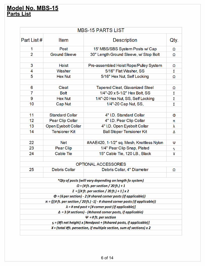
Installation Notes:Lower Collars: From bottom of 1.pole slide the lower vertical cable collar, lower horizontal collar and and debris ring (optional) into position. To allow proper insertion into ground sleeve, lower most collar should be 28" from end of post. Before securing collars into place make sure to rotate the lower vertical collar approx 40°. (refer to diagram)
Cleat: Is to be installed so that it is 2.on backside of post, opposite net. Screws will be inserted through post and cleat and secured on the opposite net side using thin self locking hex-nuts and cap nuts. (refer to diagram
Mid Collar: Note orientation of 3.collar on post. From top of pole slide the open eyebolt collar into position (refer to diagram) and secure into place.
Eyebolt: Pulley system comes 4.preassembled to eyebolt. Install washer onto eyebolt then insert eyebolt with washer through front side of hole at top of post. From opposite side secure eyebolt into place using a flatwasher and self-locking hex-nut. (refer to diagram)
Upper Collar: From top of pole 5.slide the upper vertical cable collar into position (collar should rest on eyebolt washers). Before securing into place make sure to rotate the collar approx 40°. (refer to diagram)
Make sure warning labels are 6.present on goal posts.
Note:Post assembly should be done with post laying down on flat level surface.
Collars are Black in color, shown in different colors to aid in identification.
If not present make sure lower collars are positioned
accordingly.
Net Pulley System
RightView
Post Cappre-installed
Lower Horizontal Cable Collarw/ Pear Clip
FrontView
CleatDetail
6
107
1
Apply supplied Anti-seize to bolt threads
9
9
EyeboltDetail
3
4
5
Apply supplied Anti-seize to bolt
threads
Collar OrientationDetail
(Note: ONLY vertical cable collars should be turned away from netting,
this aids in tensioning the net)
LabelDetail
AAEI.D. Label
Cleat WarningLabel
Installation Notes:Lower Collars: From bottom 1.of pole slide the lower horizontal collar and and debris ring (optional) into position. To allow proper insertion into ground sleeve, lower most collar should be 28" from end of post. Before securing collars into place verify correct orientation. (refer to diagram)
Cleat: Is to be installed so that 2.it is on backside of post, opposite net. Screws will be inserted through post and cleat and secured on the opposite net side using thin self locking hex-nuts and cap nuts. (refer to diagram)
Eyebolt: Pulley system comes 3.preassembled to eyebolt. Install washer onto eyebolt then insert eyebolt with washer through front side of hole at top of post. From opposite side secure eyebolt into place using a flatwasher and self-locking hex-nut. (refer to diagram)
Upper Collar: From top of 4.pole slide the upper vertical cable collar into position (collar should rest on eyebolt washers). Before securing collars into place verify correct orientation. (refer to diagram)
Make sure warning labels are 5.present on goal posts.
Note:Post assembly should be done with post laying down on flat level surface.
Collars are Black in color, shown in different colors to aid in identification.
(Note: ONLY vertical cable collars should be turned away
from netting, this aids in tensioning the net)
LabelDetail
AAEI.D. Label
WarningLabel
Cleat
EyeboltDetail
Apply suppliedAnti-seize tobolt threads
5 3
4
CleatDetail
7
16
9
9
10
Apply suppliedAnti-seize tobolt threads
Installation Notes:Lower Collars: From bottom 1.of pole slide the lower vertical cable collar, lower horizontal collar and and debris ring (optional) into position. To allow proper insertion into ground sleeve, lower most collar should be 28" from end of post. Before securing collars into place make sure to rotate the lower vertical collar approx 40°. (refer to diagram)
Cleat: Is to be installed so that 2.it is on backside of post, opposite net. Screws will be inserted through post and cleat and secured on the opposite net side using thin self locking hex-nuts and cap nuts. (refer to diagram
Eyebolt: Pulley system comes 3.preassembled to eyebolt. Install washer onto eyebolt then insert eyebolt with washer through front side of hole at top of post. From opposite side secure eyebolt into place using a flatwasher and Nylock hex-nut. (refer to diagram)
Upper Collar: From top of 4.pole slide the upper vertical cable collar into position (collar should rest on eyebolt washers). Before securing into place make sure to rotate the collar approx 40°. (refer to diagram)
Make sure warning labels are 5.present on goal posts.
Note:Post assembly should be done with post laying down on flat level surface.
Collars are Black in color, shown in different colors to aid in identification.
(Note: ONLY vertical cable collars should be turned away
from netting, this aids in tensioning the net)
Shared End PostBottom Collar
Detail
Installation Notes:Lower Collars: From bottom 1.of pole slide the lower vertical cable collar, lower horizontal collar and and debris ring (optional) into position. To allow proper insertion into ground sleeve, lower most collar should be 28" from end of post. Before securing collars into place make sure to rotate the lower vertical collar approx 40°. (refer to diagram)
Cleat: Is to be installed so that 2.it is on backside of post, opposite net. Screws will be inserted through post and cleat and secured on the opposite net side using thin self locking hex-nuts and cap nuts. (refer to diagram
Eyebolt: Pulley system comes 3.preassembled to eyebolt. Install washer onto eyebolt then insert eyebolt with washer through front side of hole at top of post. From opposite side secure eyebolt into place using a flatwasher and Nylock hex-nut. (refer to diagram)
Upper Collar: From top of 4.pole slide the upper vertical cable collar into position (collar should rest on eyebolt washers). Before securing into place make sure to rotate the collar approx 40°. (refer to diagram)
Make sure warning labels are 5.present on goal posts.
Note:Post assembly should be done with post laying down on flat level surface.
Collars are Black in color, shown in different colors to aid in identification.
Net Hoist:Orientation(all posts) towards field of play
Lower Collars:Orientation(all posts) towards field of play (refer to post assembly pages)
Post / GroundsleeveInstallation
SlowlyLower
post intosleeve.
Post / GroundsleeveInstallation (fully seated)
Postwill stop
once it restson stop bolt
After posts have been lowered into place, secure the lower collar(s) into place.
Installation Notes:View above is from net side of post (field 1.of play).
Caution, slowly lower posts into sleeves. 2.Dropping post into sleeve may result in damage to the stop bolt.
Make sure all posts are orientated 3.correctly. Pulley system towards field of play and cleet away from field of play. All lower horizontal cable collars should face field of play.
Once posts are correctly orientated, make 4.sure the lower collars are properly orientated and secure them into place.
View from field of Play
Note: number of inner posts may vary from what is shown.
After cable has been fully tensioned trim back cut end and wrap with tape
Thimble(must be present) Support Cable vinyl
jacket must be stripped from cable loop end
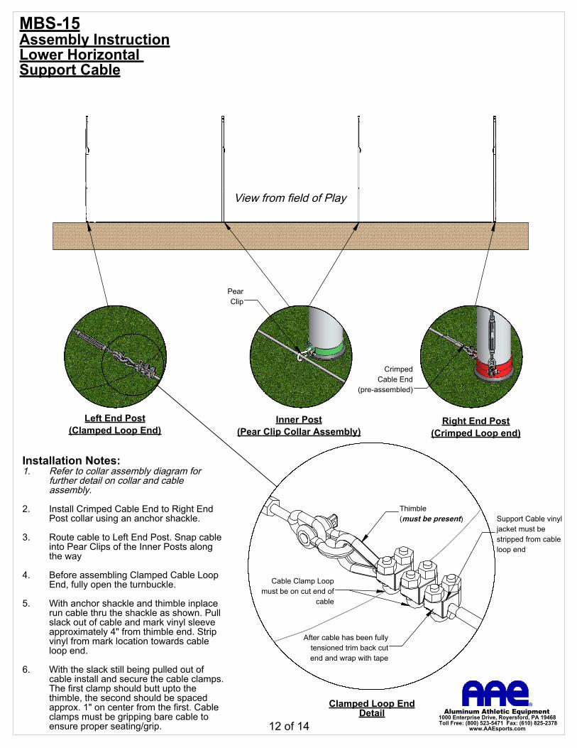
Installation Notes:Refer to collar assembly diagram for 1.further detail on collar and cable assembly.
Install Crimped Cable End to Right End 2.Post collar using an anchor shackle.
Route cable to Left End Post. Snap cable 3.into Pear Clips of the Inner Posts along the way
Before assembling Clamped Cable Loop 4.End, fully open the turnbuckle.
With anchor shackle and thimble inplace 5.run cable thru the shackle as shown. Pull slack out of cable and mark vinyl sleeve approximately 4" from thimble end. Strip vinyl from mark location towards cable loop end.
With the slack still being pulled out of 6.cable install and secure the cable clamps. The first clamp should butt upto the thimble, the second should be spaced approx. 1" on center from the first. Cable clamps must be gripping bare cable to ensure proper seating/grip.
View from field of Play
MBS-15Assembly InstructionLower Horizontal Support Cable
12 of 14
A
Multi-Section SystemCorner Attachment
(shown in raised position)
Net Vertical1/4" MFP
Double BraidedRope Border
Net "A" Net "B"
Upright"Shared End Post" configuration
Net Vertical1/4" MFPDouble BraidedRope Border
DETAIL A
Cable Ties40 lbs.
StrengthPear ClipsSpaced approx. every 12", entire length of vertical cable (Left, Right & Shared End Posts)
23
24
22 22
Installation Notes:This instruction applys to multi-section systems, if assembling single section/net system proceed to "Net Attachment" page.
assitance from a second person is •required to completed this task.task should be completed prior to raising •the net.Starting at top of the nets ensures •alignment across the top edges of the nets being joined together.One cable tie per nets square is •recommended.Starting with the top corners of Nets A & B, 1.hold togther both of the adjacent side rope borders and align the top rope borders of nets A & B.
Once the top borders of nets A & B are 2.aligned. Secure both the vertical rope borders together as close as you can to the top rope border using provided cable tie.
Begin securing the vertical borders together 3.using provided cable ties. Work your way down the net in about 2' sections, making sure that both vertical rope borders are taut as you proceed.
MBS-15Assembly InstructionMulti-Section System Net Preparation
Note: When raising net, it must be done in increments across the entire span
B
D
Hoist SystemDetail B
Pear Clip(pre-installed)
B
Net to End Post Vertical Support Cable
Detail C
Pear ClipsSpaced approx. every 12", entire length of vertical cable (Left and Right End Posts Only)
23
22
B
BrassRing
Top of net is bound
to a steel cable
CableClamp
Hold-down CableDetail D
Cable Tiesspaced appoximately every 6", entire length of Hold-down cable.
24
Installation Notes:Lay net on ground across span of posts. 1.Make sure net is centered accross span of posts.
Using a Pear Clip Secure upper net 2.corners to End Post Vertical Support Cables (as shown in Detail C)
Secure Brass Rings to top of net using 3.Cable Clamp (as shown in Detail A). One ring and clamp per post and they should be centered as close as possible to its coinciding post.
After Brass Rings have been secured to 4.net, clip ring into it's posts hoist system Pear Clip (as shown in Detail B).
As net is being raised make sure to 5.secure net sides to the vertical support cables using provided Pear Clips (refer to Detail C). Pear Clips should be spaced approx. 12" or 9 net squares.
Once net has been completed raised tie 6.hoist ropes onto cleat.