AAII 9U AMY ELECTR.ONICS RESE RC AND DEVELOPMENT C.ANO Vs--TC F / 6 o, AN IMPROVED SMOKE OSCURATION MODEL ACT I. PART 1. TIEONY.IU) JAN 8* t A SUTIER.AND* D V NOOCK UNCLASSIFIED EItADCOM/AS-f-0104 Elnnunuuunuu mnnnEEEnunununE mEnhlnEIhhIhEE
Transcript
AAII 9U AMY ELECTR.ONICS RESE RC AND DEVELOPMENT C.ANO Vs--TC F / 6 o,AN IMPROVED SMOKE OSCURATION MODEL ACT I. PART 1. TIEONY.IU)JAN 8* t A SUTIER.AND* D V NOOCK
UNCLASSIFIED EItADCOM/AS-f-0104
Elnnunuuunuu
mnnnEEEnunununEmEnhlnEIhhIhEE
-H 111112
I 1.8IIIIII' 8
MI1RCP.25 ION 1.6
MICROCOPY RESOLUTION TEST CHARTNATCNAL R)[ AH (- I TANP-.AI 1'f, A
JmzzTR-0 104 Reports Control Symbol
OSD - 1366
AN IMPROVED SMOKE OBSCURATION MODEL ACT HI:
PART 1 THEORY
SJANUARY 1982
By
R. A. Sutherland
D. W. Hoock
DTIC
Approved for public release; distribution unlimited. MR1
US Army Electronics Research ansi Development Command
The findings in this report are not to be construed as anofficial Department of the Army position, unless so desig-nated by other authorized documents.
The citation of trade names and names of manufacturers inthis report is not to be construed as official Governmentindorsement or approval of commercial products or servicesreferenced herein.
Disposition
Destroy this report when it is so longer needed. Do notreturn it to the ariginator.
SECURITY CLASSIFICATION OF THIS PAGE (When Date __t_ _ _ _
26S AWT RACTr (Ce-eyfe s Ifneemy am fdely, by block minber)
_- This report describes the theoretical basis for the smoke obscuration modelACT II. The work encompasses analytical procedures for determining smokeconcentration, temperature, path integrated concentration, path radiance, pathluminance, target and background radiance, target-background luminance, andcontrast transmission. The model includes both single scattering and thermal
wO I re* 14f3 E oN oF I wov s IS OBmLET
SECURITY CLASSIFICATION OF THIS PAGE (When Deta Rnterd)
41... - - .'r . ' .*-
SECURITY CLASSIFICATION OF THI1S PAGQWh DM& MaeuuWdf
20. ABSTRACT (cont)
]---- emission and is applicable for wavelengths from the visible through theinfrared. Data from Smoke Week 11 are used to present an examle ofinput/output.-
2 _____________________SECURITY CLASSIFICATION OF THIS PAGE(Whwfl Date Itnter.eo
CONTENTS
LIST OF TABLES ............................................................ 4
LIST OF FIGURES ........................................................... 5
1. Diffusion Parameters used in the Transport and DiffusionRoutine for Various Values of Roughness Parameter Rd0and Stability Category ........................................... 29
2. Ambient Radiation Measurements (Visible) fromSmoke Week II, Trail 1 Field Test ............................ 30
3. Meteorological Inputs to the Model for Smoke Week II,Trial 1 Field Test............................................... 31
4
LIST OF FIGURES
1. Sketch demonstrating the effects of extinction and path radianceon radiant energy received by an observer ............................. 32
2. Sketch demonstrating the scattering of ambient radiation intothe LOS ............................................................... 32
3. Sketch demonstrating the sky/terrain sectoring scheme used inthe model ............................................................. 33
4. Sketch demonstrating the geometry for computing opticalthickness ............................................................ . 33
5. Photopic response curve and Gaussian functional fit forconverting radiance (WI.2) to luminance (candles/M2 ) .................. 34
6. Test configuration for Smoke Week II, Trial 1 Field Test .............. 35
7. Sky radiance map W sr-1 m-2 as derived fromSmoke Week II, Trial I Field Test ..................................... 35
8. Model comparisons of path integrated concentration (CL)and path luminance with data from Smoke Week II, Trial 1Field Test ............................................................ 36
9. Modeled diffuse and direct radiation as a function oftarget position along the LOS ......................................... 37
5
--- A
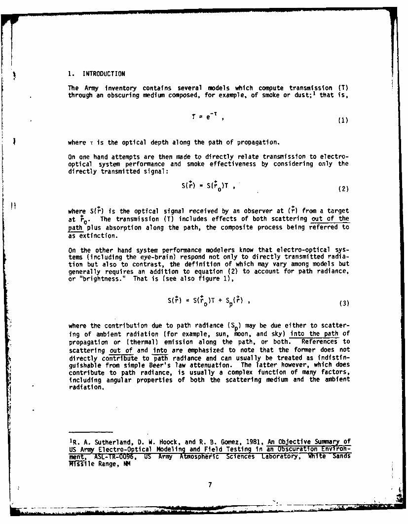
1. INTRODUCTION
The Army inventory contains several models which compute transmission (T)through an obscuring medium composed, for example, of smoke or dust;1 that is,
T e (1)
where T is the optical depth along the path of propagation.
On one hand attempts are then made to directly relate transmission to electro-optical system performance and smoke effectiveness by considering only thedirectly transmitted signal:
S(r) S( )T (2)
where S(r) is the optical signal received by an observer at (r) from a targetat +o The transmission T) includes effects of both scattering out of thepath plus absorption along the path, the composite process being referred toas extinction.
On the other hand system performance modelers know that electro-optical sys-tems (including the eye-brain) respond not only to directly transmitted radia-tion but also to contrast, the definition of which may vary among models butgenerally requires an addition to equation (2) to account for path radiance,or "brightness." That is (see also figure 1),
H =p S(ro0)T + S ' r (3)
where the contribution due to path radiance (Sp) may be due either to scatter-ing of ambient radiation (for example, sun, moon, and sky) into the path ofpropagation or (thermal) emission along the path, or both. References toscattering out of and into are emphasized to note that the former does notdirectly contribute to path radiance and can usually be treated as indistin-guishable from simple Beer's law attenuation. The latter however, which doescontribute to path radiance, is usually a complex function of many factors,including angular properties of both the scattering medium and the ambientradiation.
1R. A. Sutherland, D. W. Hoock, and R. B. Gomez, 1981, An Objective Summary ofUS Army Electro-Optical Modeling and Field Testing in an Obscuration Environ-ment, ASL-TR-0096, US Army Atmospheric Sciences Laboratory, White SandsMissile Range, NW
7
Note that, unlike transmission, path radiance has a vector nature which meansphysically that in real world scenarios, such as the smoked battlefield, asym-metries exist between target and observer, giving one or the other an "opticaladvantage." This vector nature is the essence of the present model and shouldnot be overlooked in the deceptively simple form of equation (3) or by thenecessarily complex formulation to follow.
The existence of path radiance in real world scenarios is often of overridingsignificance in affecting perception and is commonly observed in nature. Oneexample is the apparent disappearance of stars in daytime. Another is experi-enced by individuals driving a vehicle through fog with the headlights on highbeam. In both cases perception is diminished due to interference caused byscattering that is manifested by path radiance. In the infrared the effect ofpath radiance is to (partially) offset the effects of absorption. Anotherexample is radiance data sensed via orbiting satellites. Often such data arehighly accurate (-1C)2 3 when inverted to obtain surface temperature. Thisaccuracy occurs despite the fact that the path transmission in these cases,even in the so-called atmospheric "windows," is only on the order of 60 per-cent, which if taken alone would imply a corresponding temperature error onthe order of 50 to 100°C! The explanation here lies in the basic physics ofinfrared propagation in which, for practical scenarios, absorption is alwaysaccompanied by Kirchhoff (i.e., thermal) emission as elucidated for the caseof the atmosphere in early works.
4 5
The degree to which scattering and/or emission can be important is indicatedby the optical properties of the medium; the best indicators are the massextinction coefficient (a) which influences total extinction, the singlescattering albedo (Zo) which indicates the fractional amount of scattering,and 1 - wo which indicates the fractional amount of absorption.
2R. A. Sutherland et al, 1979, "A Real Time Satellite Data Acquisition,Analysis and Display System-A Practical Application of the GOES Network," JAppl Meteorol, 3:355-360
3E. Chen et al, 1979, "Satellite-Sensed Winter Nocturnal Temperature Patternsof the Everglades Agricultural Area," J Appl Meteorol, 8:992-1002
4C. D. Kern, 1965, "Evaluation of Infrared Emission of Clouds and Ground asMeasured by Weather Satellites," Environmental Research Papers, No. 155,AFCRL-65-840, Air Force Cambridge Research Laboratories, Hanscom Air ForceBase, MA
5S. M. Greenfield and W. W. Kellogg, 1960, "Calculations of AtmosphericInfrared Radiation as seen from a Meteorological Satellite," J Meteorol,6:283-290
8
Inventory smokes have w0+1 in the visible,6 indicating a predominance of scat-tering, and w0-O in the infrared, indicating a predominance of absorption, andconsequently emission. Thus path radiance is important and perhaps even ofoverriding significance for inventory smokes from the visible through theinfrared.
The need for further model development in this area was established in anearlier study' which made a detailed examination of the Army inventory ofexisting smoke and dust obscuration models. A major finding of this work wasthat although most models reported capabilities for treating attenuation, allwere deficient in wholly treating path radiance for wavelengths through theinfrared.
As a step toward filling this technological gap, an improved smoke obscurationmodel reported herein was developed. Since three of the models studied (SOM11, 7 HECSOM, 8 and ACT-I, 9 did report some capabilities in the visible, themost promising, ACT-I,* was chosen as a starting point (hence the acronymACT-II for the present model).
The approach is to provide optical information critical to the needs of pres-ently existing electro-optical system performance and smoke effectivenessmodels. An informal survey disclosed that the requirements were reducible tothe following fundamental quantities:
1. Ambient irradiance (light level),
2. Target and background radiance,
6R. C. Shirkey and R. A. Sutherland, 1981, "Aerosol Phase Function Data Base,"chapter 16, EOSAEL 80, Volume I, Technical Documentation, editor L. 0. Duncan,ASL-TR-0072, US Army Atmospheric Sciences Laboratory, White Sands MissileRange, NM (AD B055130L)
1R. A. Sutherland, D. W. Hoock, and R. B. Gomez, 1981, An Objective Summary ofUS Army Electro-Optical Modeling and Field Testing In an Obscurant Environ-ment," ASL-TR-U9b, US Army Atmospheric Sciences Laboratory, White sandsNfTsile Range, NM
7Smoke Obscuration Model II (SOM II) Computer Code Volume II - Analyst Manual,1979, JILUG/ME Smoke and Aerosol Working Group Document 61, JTCGIME-1'-9-Z
8R. K. Dumbauld and H. Bjorklund, 1977, Mixing Layer Analysis Routine andTransport/Diffusion A plication Routine fOr EPAMS, EGOM-77-Z, AtmosphericSciences Laboratory, US Army Electronics Command, hite Sands Missile Range,
~NM
9R. B. Gomez, R. Pennsyle, and 0. Stadtlander, 1979, "Battlefield ObscurationModel, ACT I," Proceedings of Smoke Symposium III, Harry Diamond Laboratories,Adelphi, MD
*The acronym ACT derives from the developing agencies Atmospheric SciencesLaboratory, Chemical Systems Laboratory, and TRASANA. -
9
_____ -. m.~--
3. Line of sight (LOS) transmission, and
4. LOS path radiance,
where target and background radiances are computed for both the unperturbed(smoke free) and smoked environment, and LOS data are provided for both theobserver-target and observer-background. From these fundamental quantitiesother specialized data such as contrast or apparent resolvable temperature canbe determined easily for input to existing system performance and smoke effec-tiveness models such as the target acquisition model of the Night Vision andElectro-Optics Laboratory"° or the munition expenditures models described byPennsylel and Hoock. 12
In another respect care is taken so that the (present) model inputs are com-patible with the outputs of other associated models such as LOWTRAN 13 andAGAUS14 as well as with data collected during field tests such as Smoke Weekll.15
Although the primary focus is on optical phenomena, the important aspect ofobscurant transport and diffusion has not been ignored. The approach here isto generalize procedures so that the model will accommodate any arbitraryensemble of Gaussian smoke clouds, providing a convenient framework for possi-ble future union with equivalent generalized transport and diffusion models.Most present models, however, do not provide cloud temperature which is criti-cal for the infrared. Thus a Gaussian diffusion model was developed based
10"Combat Simulation Target Acquisition Model and Data Input" (U),CONFIDENTIAL, 1980, Draft Technical Report, US Army Night Vision and Electro-Optics Laboratory, Fort Belvoir, VA (in process)
11R. 0. Pennsyle, 1979, Methodology for Estimating Smoke/Obscurant MunitionExpenditure Requirements, ARCSL-TR-79022, Chemical Systems Laboratory,Aberdeen Proving Ground, MD
12D. W. Hoock, 1981, "SCREEN," chapter 5, EOSAEL 80, Volume 1, TechnicalDocumentation, editor L. D. Duncan, ASL-TR-OOI0, US Army Atmospheric SciencesLaboratory, White Sands Missile Range, NM (AD B055130L)13j. E. Selby et al, 1978, "Atmospheric Transmittance/Radiance: Computer CodeLOWTRAN 4," Environmental Research Papers, No. 626, AFGL-TR-78-0053, Air ForceGeophysics Laboratory, Hanscom Air Force Base, MA14R. C. Shirkey et al, 1980, Single Scattering Code AGAUSX: Theory, Applica-
tions, Comparisons, and List n, ASL-TR-OUOZ, US Army Atmospheric SciencesLaboratory, White Sands Missile Range, NM
150PG Final Test Report on Smoke Week II at Eglin AFB, FL (U), CONFIDENTIAL,1978, Volumes I and II, DPG-FR-78-317, Dugway Proving Ground, UI
10
upon commonly used procedures 1 6 17 and extended to include buoyant rise andcloud temperature using fundamental principles.
18 19
The work is divided into three parts: the present work covers theory andexamples, a second 20 covers program documentation and a users guide, and athird21 covers validation and applications.
:Istorlcally the problem of path radiance and its significance to visibleperception have been recognized by the Army modeling community for severalyears. As early as 1972 an unpublished document described a smoke obscurationmodel (SOM) which reported to compute visible contrast and was later acceptedas the Joint Technical Coordinating Group (JTCG) working model. This earlymodel was expanded by at least two groups, one leading to the development ofthe model SOM II7 and another to ASLSOM which was further modified to becomethe ACT model9 which is the direct forerunner of the present model.
2. OUTLINE AND SCOPE
The fundamental optical quantities to be determined in addition to transmis-sion are the amounts of radiant energy received by an observer from the twodirections (approximately coincident) defined by the relative positions of a
16Smoke Effectiveness Manual, 1979, JTCG/ME Smoke and Aerosol Working GroupDocument Number FM 101-61-8
17F. V. Hansen, 1979, Engineering Estimates for the Calculation of AtmosphericDispersion Coefficients, ASL Internal Report, US Army Atmospheric SciencesLaboratory, White Sands Missile Range, NM
18F. Pasquill, 1974, Atmospheric Diffusion, second edition, Halsted PressDiv., John Wiley and Sons, Inc., New York19C. H. B. Priestley, 1956, "A Working Theory of the Bent-Over Plume of Hot
Gas," Quart J Roy Meteorol Soc, 82:165-176
20R. A. Sutherland and D. Clayton, 1981, An Improved Smoke Obscuration Model
Act II: Part 2 Documentation and User Guide, Technical Report, US Army Atmo-spheric Sciences Laboratory, White Sands Missile Range, NM (in process)
2 1R. A. Sutherland, 1981, "Comparisons Between the Improved Smoke ObscurationModel ACT II and Recent Smoke Week Data," Proceedings of Smoke Symposium V,Harry Diamond Laboratories, Adelphi, MD
7Smoke Obscuration Model II (SOM II) Computer Code Volume II - Analyst Manual,1979, JTGG/ME Smoke and Aerosol Working Group Document 61, JTCG/ImE-78-9-Z
9R. B. Gomez, R. Pennsyle, and D. Stadtlander, 1979, "Battlefield ObscurationModel, ACT I," Proceedings of Smoke Symposium III, Harry Diamond Laboratories,Adelphi, MD
11
' - ' r ii( ' ' - -
. .. . t .. .. " .. .. . .... k ...... . . , , i . J .T
target and background, both treated as Lambertian surfaces. The radianceincident at the observer from each direction is generally composed of twoparts: (1) the direct radiance emitted and reflected by the target (or back-ground) then transmitted (with some loss due to extinction) along the LOS tothe observer and (2) the diffuse, or path, radiance emitted and scattered bysuspended material (smoke) at all points (such as P in figure 2) along the LOSthen transmitted (again with some loss due to extinction) a remaining distanceto the observer, giving rise to a path radiance. One aspect of the problemwhich causes major complexity is that the entire environmental sphere must beconsidered the source for the reflected and diffuse radiation, thus requiringintegration over all angles, not only at the target and background but also atall points along the LOS. Except for rare circumstances, these integrationsmust be carried out by some approximate numerical technique. The approachtaken here is to divide the sky hemisphere into discrete angular sectors andthen assume that the radiances from the various sectors are either known frommeasurement (as in recent field tests) or produced by some appropriate model(perhaps LOWTRAN1 3). Terrain radiance due to reflected sky radiation andthermal emission can then be calculated from knowledge of surface albedo,emissivity, and temperature to complete the characterization of the (smokefree) radiation environment, which is then assumed constant throughout. Theexact sectoring procedure used in the model is outlined in section 3.
Mathematically the problem can be summarized by the following formal expres-sion describing radiant propagation along a straight path over a distance r.
where R(r) is the radiance incident at r; R(r o ) is the radiance of the target(or background) located at ro; and 0, * are the polar angles defining the pathof propagation (that is, the LOS). Although the vector notation will bedropped, it is assumed here and in the following that the observer is at theorigin and that the coordinates are rotated so that + and +' lie along the LOS(figure 4). Generally the term J(r, e, *) (called the source function)accounts for scattering into the LOS, and (1 -Zo)B(X, T p) accounts for emis-sion from increments along the LOS.
13j. E. Selby et al, 1978, "Atmospheric Transmittance/Radiance: Computer CodeLOWTRAN 4," Environmental Research Papers, No. 626, AFGL-TR-78-0053, Air ForceGeophysics Laboratory, Hanscom Air Force Base, MA
22S. Chandrasekhar, 1960, Radiative Transfer, second edition, Dover PressPublications, Inc., New York
12
The Planck or blackbody function of equation (4) is written explicitly as
B(, Tp)= 2hc2 x-5 AXT exp(hc/kTp) - 1]
where X is the wavelength, AX the bandpass, and h, k, and c are, respectively,the Planck constant, the Boltzmann constant, and the speed of light in vac-uum. The obscurant temperature (Tp) is assumed variab'le over the path, sothat B contains an implicit dependence on r.
The optical thickness (T) is defined as
rr') aC(r")dr" ,(6)
r
where a is the obscurant mass extinction coefficient and C is the obscurantconcentration. Both obscurant temperature and concentration are discussed insection 5.
The source function J(r, 8, f) is difficult to compute, requiring integrationsover the entire environmental sphere accounting for the angular characteris-tics of both the ambient radiation and the scattering medium. Except fortrivial cases, no exact methods exist for computing this term; and for real-istic scenarios, some approximate technique must be employed. The model usesthe single scattering approximation in which the source function can bewritten as
1~r 0, P(. s LWO, ')e - r rs dnz'J(r, 8, *) =)e r 4 ' (7)
4nr
where e is the scattering angle (figure 2) and P the phase function. Theterm LIE , 0') consists of two parts: the source radiance R (', *') fromthe directions of the sky and terrain sectors and the thermal emission alongthese same directions. Mathematically,
rs
L(', ') = Rs (e', *') + (i - zo) f B(), Tp)e [ T (r ' rs)-T(r, r')]dr, (8)r
In the above expressions, r is distance to any point along the LOS; r' isdistance from that point along the direction defined by 8', o'; rs is distanceto the sky and terrain sources; and dnl' is the differential solid angle.
13
For inventory smokes (and neglecting polarization), the angular dependence ofthe phase function is dependent only upon the scattering angle, which fromsimple geometry is given by (see figure 2):
cos es = [cos 0 cos e' + sin e sin 6' cos(O - ')]. (9)
Some caution is required in using equation (9) to assure the proper algebraicsign. For use in the phase function equation (9) is correct as it stands, butfor Lambertian surfaces (that is, target, background, etc.) the sign must bereversed because the convention used in the model requires the surface normalpointing positive inward (for example, away from the observer) which in turnrequires the reversal in sign.
The phase function is required as input but can readily be obtained from theassociated model AGAUS,14 one version of which is distributed with theElectro-Optical Systems Atmospheric Effects Library (EOSAEL 8023). The phasefunction is assumed to be normalized such that
Ti 4 d (10)
but in the model it is renormalized via equation (10) to a single scatteringalbedo specified as input. However, to be strictly compatible with theory theinput single scattering albedo should be that computed from Mie scattering.
The major objective of the model is to evaluate the two components of equation(4), once for the observer-target and once for the observer-background byusing the procedures described by equations (4) through (9). For the specialcase of computing R(ro), the target or background radiance, the same procedure
for the second term of equation (4) is used except that the factor __ P(6s ) inequation (7) is replaced by (a sos %_/w) which assumes a Lambertian surface ofalbedo* (a) with surface normal alonsg the LOS. Also for these cases the com-putations are restricted to > 900 to avoid contributions due to reflectionfrom the rear surface. The (smoke free) surface irradiance (Esfc) is alsocomputed in the same manner with 0 = = 0 (vertical) and the factor 1/7
14 R. C. Shirkey et al, 1980, Single Scattering Code AGAUSX: Theory, Apelica-tions, Comparisons, and Listing, ASL-IR-U~bZ, US Army Atmospheric Sciences
Laboratory, Wite Sands m'issile Pange, NM
2 3R. A. Sutherland, 1981, "Smoke Obscuration Model," chapter 3, EOSAEL 80,Volume 1, Technical Documentation, editor L. D. Duncan, ASL-TR-O0O127Us IiiAtmospheric Sciences Laboratory, White Sands Missile Range, NM (AD B055130L)
*For opaque surfaces, reflectivity (r), albedo (a), and emissivity (C) are
related as (a = r and e = 1 - r).
14
I removed. In all cases, an emission term of the form EB(X, T) is added where Tis chosen appropriately as the surface, target, or background temperature, andthe emissivity (0) is computed from the reflectivity or albedo as c = (1 -a). The (smoke free) surface irradiance is used later (see equation (18)) tocompute radiances for terrain sectors which are then treated in the samemanner as sky sectors.
For the visible scenarios, the effect of emission will be negligible becauseof the small ness of the bl ackbody function in these spectral regions atnominal temperatures. For infrared scenarios, this term often dominates,being more pronounced at higher temperature, which means that errors due toneglect of multiple scattering will be minimal in the infrared. However,errors may occur in the infrared due to uncertainties in the cloud tempera-ture.The process to be modeled here can be summarized in geometrical terms with theaid of figure 2. Simply stated, the problem is to compute contributions topath radiance at each point P along the LOS, and then to sum over all suchpoints. At each increment, effects of extinction must be included over theremaining path M to the observer. At each point P the contribution is com-posed of two parts--one due to scattering into the increment from all anglesand the other due to emission by the increment. The single scatteringapproximation assumes that the radiance along any path 7F is scattered intothe LOS only once and that this scattering occurs at P. Thus the radiancescattered into the LOS at point P consists of the source radiance, R5, reducedby extinction over the path 7W, plus the summation of the emission from eachelement P' along the rdth 3P; the emissive contribution of each element isreduced by extinction over the path PP'. The total scattering contribution ofeach increment at P is found by summing over all angles, accounting forangular scattering properties of the medium via the phase function. Totalpath radiance is found by summing over all increments along DT.
In the model the increment spacings are chosen by a criterion based upon theincremental optical depth ATr. This method speeds computations by avoidinginsignificant contributions for increments containing no obscurant which wouldoccur for a criterion based on spatial separation (ztr). The minimum spacingin the model however is normally defaulted to 1 m.
The model treats extinction due to the ambient atmosphere by appropriatelymodifying transmission (i.e., TLOS 7-Tsm T #~0 ) for propagation along theLOS. This option is employed by way of a user supplied volume extinction
coeficiet, a), o t atmo * e'1 where L is distance of propagation.Parallel point sources of radiation, including the sun or moon, are alsotreated by the model.
In all of the above computations, the model computes optical thickness (T) byassuming the medium composed of any ensemble of obscuring smoke clouds definedby centrold locations, Gaussian standard deviations, and temperature. Methodsfor integrating equation (6) and for producing the ensemble are given in latersections of the report.
15
3. AMBIENT IRRADIANCE (SECTORING SCHEME)
This section describes the sectoring scheme used to simulate incoming radia-tion from sky and terrain which will then be used to approximate terms for thesource function of equation (8). Throughout this section repeated use will bemade of approximations, assuming that scenario relative distances are small incomparison to spatial variations in ambient conditions. This process consid-erably simplifies the geometry by allowing all scenario elements to be treatedas exposed to the same ambient radiational environment. These are approxima-tions often used in problems of this type and introduce only minimal errors.
The major divisions of the entire 4-f steradians comprising the environmentalsphere are sketched in figure 3. The upper sector is assumed to be comprisedof sky (including sun, moon, and clouds) and the lower to be overall flat ter-rain. Both sky and terrain will be treated as sources of ambient radiation,the latter through reflection of sky radiation and thermal emission.
To facilitate computations, the two major regimes are further subdivided intoangular sectors subtending equal solid angles. These discrete sectors arethen treated as point sources of parallel radiation emanating from the direc-tion of the sector midpoint. Additional sources of radiation such as the sunor moon are superimposed at their appropriate angular positions. The modelwill accommodate variable radiance from each of the discrete sky sectors, butto maintain consistency with the assumptions mentioned earlier, one oustassume that the terrain is homogeneous in albedo, emissivity, and temperature.
The procedure for sectoring the two regimes into equal angular sectors followsdirectly from the definition of solid angle; do = sin B de do, where e and0 are the usual zenith and azimuth angles.
The azimuthal sectoring is particularly simple since integration over contig-uous divisions (0i, ot+1) yields, simply, dn, = Ao sin 0 de, where Ao =t1+1 - 0 is the azimuthal separation, which for m sectors is simply Ao =2w/m. The representative midpoints are then
For the zenith sectors, the integration between contiguous divisions yields
An = Ao(cos 6 -cos ej+ ) (12)
For n sectors, all of which are equal and contained in a total solid angle 2W,we have
Ao(cos 0e - Cos ej+ 1) = 2w/nm (13)
16
_ _ _ _ '4
which after substituting for A* and rearranging becomes
Cos ej+ C Cos e - 1/n , (14)
from which all divisions can be calculated by knowing that e1 = 0. An equiva-
lent but sometimes more convenient expression is
Cos 0 1 (j -1)l/n.(5
Further reasoning yields the following equation for sector midpoints:
cos'6 = 1 - (2j - f)/2n .1 (16)
The corresponding distances to the terrain sector midpoints are
riJ = h/cos _e, (17)
where h is the vertical distance from the surface for the particular scenarioelement under consideration. The radiance from the sector, assuming aLambertian surface is
R = [(a/w)Esfc + (1 - a)B(X, Tf)] (18)
where a, Esfc, and Tsfc are, respectively, the surface albedo, irradiance (see
section 2), and temperature. From this point on, the only difference intreating sky or terrain sectors is that the finite distance to the terrainsectors must be considered via equation (17), whereas the sky sectors can beassumed at infinity (actually 10,000 m in the model).
Ordinarily one does not have sufficient data, or the inclination, to providethe radiance values for all of the sectors used in the model; therefore, themodel was programmed to proportion the sectors uniformly by interpolating theinput radiance values from arbitrary angles. This interpolation makes themodel input directly compatible with sky radiance data from the smoke tests.
17
Also, to avoid inconsistencies between the computed surface irradiance (Esfc)and the reported measurements, 2' the sun and sky input data are treated onlyas relative and are normalized so as to reproduce the measured value whenintegrated over the sky hemisphere. Thus the model as now coded requires onlyrelative data from sun and sky but an absolute determination of surface irra-diance. In effect this method reduces the complexity of the required input.
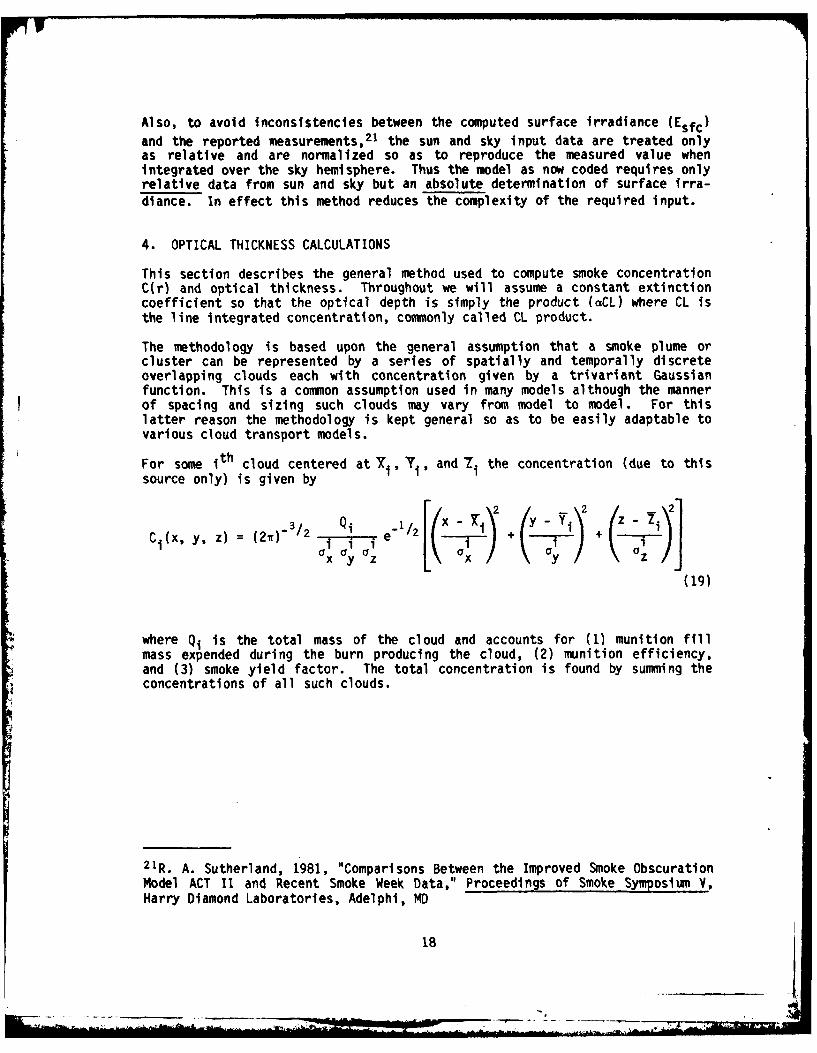
4. OPTICAL THICKNESS CALCULATIONS
This section describes the general method used to compute smoke concentrationC(r) and optical thickness. Throughout we will assume a constant extinctioncoefficient so that the optical depth is simply the product (aCL) where CL isthe line integrated concentration, commonly called CL product.
The methodology is based upon the general assumption that a smoke plume orcluster can be represented by a series of spatially and temporally discreteoverlapping clouds each with concentration given by a trivariant Gaussianfunction. This is a common assumption used in many models although the mannerof spacing and sizing such clouds may vary from model to model. For thislatter reason the methodology is kept general so as to be easily adaptable tovarious cloud transport models.
For some ith cloud centered at 71i , 7i' and 7 the concentration (due to thissource only) is given by
(x, y, z) = (21" 1--2 ii e [+ ( +
(19)
where Qi is the total mass of the cloud and accounts for (1) munition fillmass expended during the burn producing the cloud, (2) munition efficiency,and (3) smoke yield factor. The total concentration is found by summing theconcentrations of all such clouds.
2 1R. A. Sutherland, 1981, "Comparisons Between the Improved Smoke ObscurationModel ACT I and Recent Smoke Week Data," Proceedings of Smoke Symposium V.,Harry Diamond Laboratories, Adelphi, MD
18
It is convenient to rewrite equation (19) in spherical coordinates to give anexpression for concentration along an LOS defined as before by polar angles eand f at some arbitrary point a distance r from the origin. It is straight-forward to show that the equivalent to equation (19) is
(2i)- /2
C (r , 8, e1/2Q e - /2 + +,yz Q x X0Y 2 (or- )2 ( C 0,)2 0
(20)
where the indices have been dropped to avoid cumbersome notation. The lineparameters a, 6, 1 and offsets x0, Yo, Z0 are:
a = sin e sin * x0 = X -x
0= sin 0 cos € Yo = -i " Y' (21)
r = cos 0Zo = i- zI
where xi, yi, and zi are coordinates of any point on the LOS, taken in the
model to be the common point such as P in figure 4.
With considerably more algebraic manipulation which involves expanding theexpression in the exponential, rearranging and then rewriting the resultantexpression as a perfect square, the following expression results:
Ci(r, o, =Qj e/2 (r -(22)
which is itself a Gaussian with mean Ri, standard deviation zi, and strengthQ given by the following expressions, again with indices suppressed:
xa (aZ U )2 + 0 yo(ax a)2 + y zo( x y)2
(a ay az)2 + (8 Ox Uz)2 + (y ax ay)2
0x 'y 'z
[(a Uy Oz 2 + X a az)2 + (y x a y )2]1129(23)
19 I.
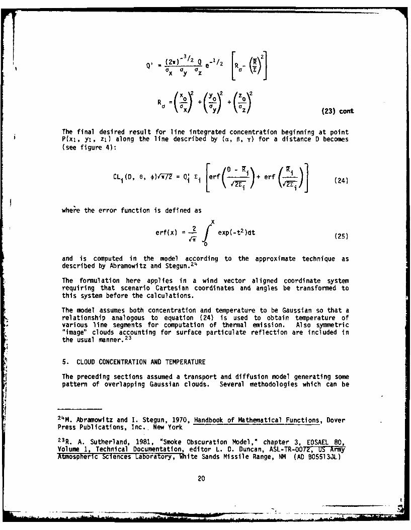
Q1 (2w)3/2 Q 1 2
R (a + (s1 (°)/ () +( (23) cont
The final desired result for line integrated concentration beginning at pointP(xi, yi, zi) along the line described by (a, 8, y) for a distance D becomes(see figure 4):
CLi(D , 0, )f-lv17 = Q! E. rf - (24
where the error function is defined as
xerf(x) = _. o exp(_t 2)dtex((25)
0
and is computed in the model according to the approximate technique asdescribed by Abramowltz and Stegun.
24
The formulation here applies in a wind vector aligned coordinate systemrequiring that scenario Cartesian coordinates and angles be transformed tothis system before the calculations.
The model assumes both concentration and temperature to be Gaussian so that arelationship analogous to equation (24) is used to obtain temperature ofvarious line segments for computation of thermal emission. Also symmetric"image" clouds accounting for surface particulate reflection are included inthe usual manner.23
5. CLOUD CONCENTRATION AND TEMPERATURE
The preceding sections assumed a transport and diffusion model generating somepattern of overlapping Gaussian clouds. Several methodologies which can be
24M. Abramowitz and I. Stegun, 1970, Handbook of Mathematical Functions, DoverPress Publications, Inc. New York23R. A. Sutherland, 1981, "Smoke Obscuration Model," chapter 3, EOSAEL 80,Volume 1, Technical Documentation, editor L. D. Duncan, ASL-TR-072, US AIWAtmospheric Sciences Laboratory, White Sands Missile Range, NM (AD B055133L)
20
adapted to this general concept are available. We borrow bits and pieces fromthese methodologies to produce a submodel to be used for the validationstudies reported later. Production of this model consists of generating the
parameters Qi,f i Y, iT), (°ax, ay, aZ), and cloud temperature which willnow be covered in order.
5.1 Smoke Source Function (Q)
The factor Q represents the total mass of a smoke cloud and is composed of theproduct of factors M, X, and Y where M is the mass of munition fill expendedduring the burn producing the cloud, X is the chemical efficiency with whichthe mass is converted to actual smoke nuclei, and Y is the smoke yield factorwhich accounts for increased mass due to hygroscopic interactions with theambient air mass.
For instantaneous bursts such as bulk fill white phosphorus munitions, asingle cloud of mass Q = M X Y is used. For munitions of extended burningtime (> 1 s), the plume is generated as a series of discrete puffs producedduring short time increments (nominally 1 s). Variable burn rate is includedby employing either a quadratic or exponential function with coefficients asdetermined empirically from field tests. The EOSAEL 80 Technical Documenta-tion23 contains a review of these burn coefficients and other munition charac-teristics.
5.2 Cloud Centroids (X, Y, and !)
With the coordinate system rotated to align the positive x axis along the windvector and assuming the cloud to be transported by the mean wind (U), thecloud centroids are modeled as
= + Xm
Ym (26)
=Z m + H(t)
where XmI Ym' and Zm are munition coordinates. The method of computing the
cloud rise function H(t) which also involves the cloud temperature is dis-cussed later. The mean windspeed is computed by averaging vertically over the
2 3R. A. Sutherland, 1980, "Smoke Obscuration Model," chapter 3, EOSAEL 80,Volume 1, Technical Documentation, editor L. D. Duncan, ASL-TR-O072, US A'imyAtmospheric Sciences Laboratory, White Sands Missile Range, NM (AD B055130L)
21
significont cloud extent (3a) using the usual windspeed power law: U(z) =
Ur(Z/Zr) where Ur is the wlndspeed at an (input) reference height (Zr) and Pis the vertical profile exponent.
5.3 Dispersion Functions (ax' ly, a Z)
The dispersion functions ax, y, a z are all expressed as power functions of
the x centroid with initial offset, a(O); that is,
yx, y,z = (o) + ( ) (T in meters) (27)
The source sigmas a(O), essentially representing the dimensions of the cloudat t = 0 are modeled by the following power functions which were derived fromthe data of AMSAA TR-201.
25
0.3S(O) =5.0 Q
x, y(Q in kilograms) (28)
z(O) = 1.7 Q
The diffusion parameters A and B of equation (27) are modeled as functions ofthe surface average roughness element (Zo) and the stability category as
listed in table 1. For surface roughness Zo > 0, the values are those cited
by Hansen; 17 and for these cases the parameter C of equation (27) is set to
zero. For a roughness entered as Z 0 O (default), the method of the Smoke
Effectiveness Manual 16 is used, in which case the initial sigmas are absorbed
in the parameter C, and the term o(O) is set to zero.
2 5 Analysls of the Smoke Cloud Data from the August 1975 Jefferson ProvingGround Smoke Test, 1977, AMSAA Technical Report TR-ZOl, Aberdeen ProvingGround, IM (AD. A045874)17F. V. Hansen, 1979, Engineering Estimates for the Calculation of AtmosphericDispersion Coefficients, ASL Internal Report, US Army Atmospheric SciencesLaboratory, White Sands Missile Range, NM
16Smoke Effectiveness Manual, 1979, JTCG/ME Smoke and Aerosol Working GroupDocument Number FM 101-61-8
22
-MLV--
) Following the methodology cited by Hansen, 17 a 9.y, and az are reduced by
factors 0.74, 0.67, and 0.67, respectively, for instantaneous sources.
5.4 Cloud Temperature and Buoyant Rise
Current methods for modeling buoyant rise are generally limited to empiricalmethods based upon observations of factory smoke stack effluents26 or curvefits to data from field tests.2 5 These procedures, although of approximatevalidity for special circumstances, have severe shortcomings for the generalcase where it becomes necessary to simultaneously model cloud temperatureconsistently. This consistency is particularly important in the infraredwhere cloud temperature acquires an added significance of its own in additionto the indirect effect on buoyancy. The method developed for the modelapplies basic principles and certain simplifying assumptions borrowing heavilyfrom earlier works 1 8 19 in a self-consistent numerical scheme as outlinedbelow.
The buoyant motion is modeled by treating each cloud of the ensemble as thoughindependent of other clouds, an assumption consistent with the transport anddiffusion methodology discussed earlier. Initial cloud temperature is modeledby equating the internal thermal energy of each instantaneous cloud to theenergy expended during the exothermal reaction producing the cloud. Assuming,as before, similar distributions in both temperature and concentration, thefollowing expression results for initial cloud temperature:
E CO + pCp TzTc - p (29)
where E is the obscurant heat of reaction (calorie/gram), CO the mean concen-
tration, pC the volumetric specific heat of the ambient air (290 cal m- 3
C-1), and Tz the ambient air temperature at the cloud centroid. The use of
equation (29) assumes complete thermal mixing between cloud and entrained air.
76 G. A. Briggs, 1965, "A Plume Rise Model Compared with Observations," J AirPoll Control Assoc, 15:433
2SAnalysis of the Smoke Cloud Data from the August 1975 Jefferson ProvingGround Smoke Test, 1977, AMSAA Technical Report TR-201, Aberdeen ProvingGround, MD (AD A045874)
18F. Pasquill, 1974, Atmospheric Diffusion, second edition, Halsted PressDiv., John Wiley and Sons, Inc., New York
19C. H. B. Priestley, 1956, "A Working Theory of the Bent-Over Plume of HotGas," Quart J Roy Meteorol Soc, 82:165-176
23
The vertical (ambient) temperature profile is modeled as
1 - exp[-cdz - Zr)/H ]Tz = Tr + T r m z < Hm/10
1 - exp[-c(Hm Z/H m]
[Thm - To >H/10T10 L H M HI/J z m (30)
T10 = Tz(Hm/lO)
where Tr is the temperature measured at the reference height (zr), Thm is thetemperature at the mixing height (Hm), and a is chosen so as to fit to themeasured ambient temperature gradient at the reference height and to theadiabatic lapse rate (0.009660C/m) at z = Hm/10.
The vertical velocity (w) at any later time is found by first applying theconservation of momentum along the vertical:
dw gdt T- AT - k (3,dTm (31)
z
where AT is cloud temperature excess, g is the acceleration due to gravity, Tzas before is the (absolute) ambient air temperature at the centroid height,and km is the momentum mixing coefficient taken to be 0.10 s-1.
19
Equation (31) with (29) and (30) is then solved for w using reiterative tech-niques assuming zero initial velocity to further determine the rise functionby way of the following kinematic relations:
w(t) = w(t - At) + (dw/dt)At;
(32)H(t) = H(t - At) + w(t)At (
19C. H. B. Priestley, 1956, "A Working Theory of the Bent-Over Plume of HotGas," Quart J Roy Meteorol Soc, 82:165-176
The process is then repeated by incrementing time (and hence C) over the "age"of the cloud. Beyond the first time increment, a term [(AT) x AC/C] issequentially added to equation (29) to account for the vertically changingtemperature of the ambient entrained air. In actual practice the time incre-ment is computed so as to limit the cloud rise increment to 1 m or less toassure convergence of the numerical procedure.
6. EXAMPLE (FROM SMOKE WEEK II)
6.1 Conversion of Model Results
As mentioned in section 1, the model was coded in such a way as to be compat-ible with measurements made during the major field tests. This coding allowsnearly direct comparison between model results and measured data. However, aword of caution is required to interpret the results appropriately.
The model has assumed radiometric units throughout, whereas the units reportedin the field tests are mixed; that is, sky and solar data are in radiometricunits, but target, background, and path radiance are in photopic units.Because the underlying spectrum is not uniform (that is, the sky is blue,clouds are white, and the sun is yellow-green), some error and confusionresult when converting between the two systems. Rather than try to correctfor the nonuniform spectrum (a procedure which could only increase the error),we choose here to assume the spectrum nearly uniform and convert the modelresults to photopic units by using the standard photopic response curve27
which can be closely approximated by the following Gaussian function (seefigure 5):
Rp = R0 exp[-1/2(X - 0 )/) 2 ] , (33)
where
R= 673 lm/W
X0 = 0.56m,
a = 0.0426um,
27A. Stimson, 1974, Photometry and Radiometry for Engineers, John Wiley andSons, Inc., New York
25
_ _ _ _ _ _ _ _ _ _
which can be integrated to yield the following conversion factor:
E(lm) = Ro0 r a E(W) , (34)
or in terms of bandwidth (full width at half maximum):
E(lm) = R0 [=n D, E(W) (35)
Both the bandwidth (AX) and position of maximum response (Xo) are input by theuser and are 0.1O0m and 0.56)jm for straight photopic conversion. For inputwavelengths other than 0.56um, the model shifts and reduces the peak responsevia a multiplicative Gaussian factor:
exp (36)
which is equal to unity for A = 0.56 and is essentially zero for theinfrared. In all cases the model also provides output in radiometric units.
Also the Smoke Week sun and sky radiances are reported for a detector field ofview of 1 requiring division by (7r/180) 2 to convert to a unit steradian.This conversion is not required for the input to the model as now coded sincethese data are used only in a relative sense. For sake of completeness, somefurther required conversion factors are:
1 footcandle = 10.76 lumens per square meter
1 footlambert 10.7 6 candles per square meter(37)
1 candle = 1 lumen per steradian
6.2 Input Data
Trial 1 of the Smoke Week II field test, held at Eglin Air Force Base,Florida, in November 1978 consisted of the detonation of 15 155-mm hexachlo-roethane (HC) Type MI canisters arranged in the configuration sketched infigure 6. The source characteristics used in the model were those as reported
26
___________________
in EOSAEL 80 Technical Documentation;2 3 and the mass extinction coefficient,single scattering 2Ibedo, and phase function were those of Shirkey, Clayton,and Quintls 28 for HC smoke. For modeling purposes, the munitions wereseparated into four groups as indicated by the sketched outlines in figure 6with each group treated as single-point detonation of appropriate totalmass. For buoyant smokes this latter procedure may cause some concern;however, for HC munitions which are only slightly buoyant this procedurecauses only insignificant errors.
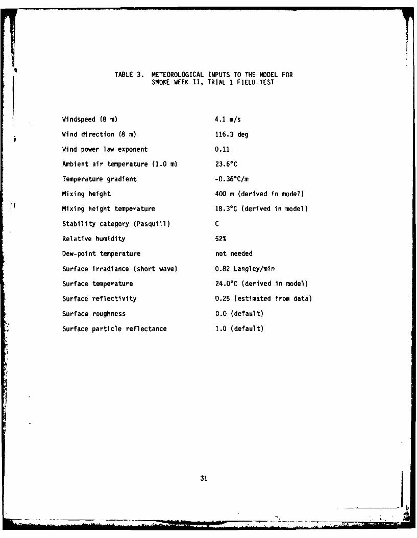
Meteorological conditions during the test were typical of fair weather with 30percent cloud cover and 11.3 km visibility. Model inputs either taken fromthe original test report or derived (estimated) from data therein are listedin table 2. Table 3 lists the ambient sky radiation measurements made duringthese tests.
The sky radiance map derived from the data of table 3 for the model sectormidpoints is shown in figure 7.
Figure 8 shows the modeled and measured results for both path integratedconcentration (figure 8a) and path luminance (figure 8b). The results forpath integrated concentration, although overall high, are typical of thosereported in other validation studies.29 The path luminance results are mostinteresting in that the brightening effect at the cloud edges is quite notice-able. This effect is often observed in natural clouds and is referred to as a"silver lining." The occurrence and magnitude of the bright edges dependstrongly upon the angular distribution of ambient radiation. The overallagreement between model data and data of figure 8b is encouraging.
Figure 9 is a more detailed examination of the cloud at time t = 100 s. Hereboth the direct and diffuse components of radiation are plotted as a functionof depth of penetration. This procedure may be viewed as moving the targetinto the cloud along the LOS away from the observer. Until a significantport -, of the cloud is penetrated, the diffuse component is near zero and the
2 3R. A. Sutherland, 1981, "Smoke Obscuration Model," chapter 3, EOSAEL 80,Volume 1, Technical Documentation, editor L. D. Duncan, ASL-TR-O072, Us AiyAtmospheric Sciences Laboratory, White Sands Missile Range, NM (AD B055130L)
28R. C. Shirkey, D. Clayton, and D. M. Qulntis, 1981, "Aerosol Phase Function
Data File PFNDAT," chapter 16, EOSAEL BO, Volume 11, Users Manual, editorsR. C. Shirkey and S. G. O'Brien, ASL-TR-0073, US Army Atmospheric SciencesLaboratory, White Sands Missile Range, NM (AD B056119)
29D. W. Hoock, R. A. Sutherland, and D. Clayton, 1981, Comparisons Between the
EOSAEL 80 Model SMOKE and the Inventory Munition Test Phase 11a, TechnicaTReport, US Army Atmospheric Sciences Laboratory, White Sands Missile Range, NM(in process)
27
__ 2
direct component is at a maximum. As the target moves into the cloud, thediffuse component increases while the direct component decreases. The neteffect Is a reduction in both the direct signal and the contrast.
A discussion of how these (and other) outputs of the model can be used inother smoke screening and perception models can be found elsewhere.30
30D. W. Hoock and R. A. Sutherland, 1981, "Path to Background Luminance Ratios
for the EOSAEL 80 Munitions Expenditure Model SCREEN," Proceedings of Smokesymposium V, Harry Diamond Laboratories, Adelphi, MD
28
TABLE 1. DIFFUSION PARAMETERS USED IN THE TRANSPORT AND DIFFUSION ROUTINE FORVARIOUS VALUES OF ROUGHNESS PARAMETER (Zo ) AND STABILITY CATEGORY.*
*Note that reported sky radiance data must be divided by (W/180) 2 to convertunit solid angle to 1 sr. Also a factor 10-2 converts UW/Cni2 to WfM 2
30
TABLE 3. METEOROLOGICAL INPUTS TO THE MODEL FORSMOKE WEEK I, TRIAL 1 FIELD TEST
Windspeed (8 m) 4.1 m/s
Wind direction (8 m) 116.3 deg
Wind power law exponent 0.11
Ambient air temperature (1.0 m) 23.60C
Temperature gradient -0.36°C/m
Mixing height 400 m (derived in model)
Mixing height temperature 18.3 0C (derived in model)
Stability category (Pasquill) C
Relative humidity 52%
Dew-point temperature not needed
Surface irradiance (short wave) 0.82 Langley/min
Surface temperature 24.0°C (derived in model)
Surface reflectivity 0.25 (estimated from data)
Surface roughness 0.0 (default)
Surface particle reflectance 1.0 (default)
31
31._________ jow
OBISCURING.
SORC (re), UN
S- CAW
Figure 1. Sketch demonstrating the sffctein of extnto adiato rainthe rainL eegOrcieS.nobevr
32RE0 eSN
SKY
I.-_
Figure 3. Sketch demonstrating the sky/terrain sectoring scheme used inthe model.
9
T (ro)
r,.
, P (X,,y,, ,)
0 (r)
Figure 4. Sketch demonstrating the geometry for computing opticalthickness.
33
10 4 rr-rVi I-T T T r r 1t r- -T r T-1 t- r-1 F'r-T
R(.58- 673 LUMENS/WATT
WO - .56 MICROMETERS --4
SIG - .0426 MICROMETERS
103,0
-- 7
J/
102.
LUI-
z~ /- -
..- I "-
10
i- 101
7. 0 " \ -U
9*-.S-/"-
11
10-35 .4 .45 .5 .55 .6 .85 .7 .75
WAVELENGTH (M1ICROM~ETERS)
Figure 5. Photopic response curve and Gaussian functional fit for convertingradiance (WM) to luinance (candles/rn2 ).
34
-- Now ..
y NORTH
-2r
WIND VECTOR
ARGET (0,0,1.5)
E- OBSERVER (-800.0,1.5) 0
Ijixx xIx xx xKxI
x 155 mm. IC
*MALFUNCTIONS
Figure 6. Test configuration for Smoke Week 11, Trial 1 Field Test.
NORTH (23')
18.4
20.9 16.8
5.
DATA
x ACT1! MODEL
S*"- *Ix
Z, 2
-j'
0 50 00 150 200 250 300
TIME - SECONDSFIGURE 8a. TRIAL 01 SMOKE WEEK II
ReOLIltf of" oompr-1 Dor o of path ir'tozed oor'oe*rstrotler-
----- DATA
X ACTI1 MODEL -
N5 0 0 or
ZIg
Z- I ZZ IU1zx
r -.L- .. ~.., LIkL -L .... -L...A ... ._-L...I _._. L . _.. L. , 4 _ ,.&.
0 50 100 150 200 250 300
TIME - SECONDS
FIGURE 86. TRIAL 01 SMOKE WEEK I IRo.ult.. o? oompar-1oormo for p~th b,-.ih*,,-,oo
Ftgure 8. Model comparisons of path Integrated concentration (CL) and pathluminance with data from Smoke Week II, Trial 1 Fteld Test.36
" ' -i .. -i " z
r-
-I n
InC
(C) w
-n
I--
* WIp-.
.1
t9
-4 '- 1
41~
GB1m
/m
NN
Z L L V M . N ! I f I
'U
'-S-
374
N NN-11
REFERENCES
1. Sutherland, R. A., D. W. Hoock, and R. B. Gomez, 1981, An ObjectiveSummary of US Army Electro-Optical Modeling and Field Testing in an ObscurantEnvironment, ASL-TR-0096, US Army Atmospheric Sciences Laboratory White SandsMissile Range, NM.
2. Sutherland, R. A., et al, 1979, "A Real Time Satellite Data Acquisition,Analysis and Display System-A Practical Application ef the GOES Network," JAppl Meteorol, 3:355-360.
3. Chen, E., et al, 1979, "Satellite-Sensed Winter Nocturnal TemperaturePatterns of the Everglades Agricultural Area," J Appl. Meteorol, 8:992-1002.
4. Kern, C. D., 1965, "Evaluation of 'Infrared Emission of Clouds and Groundas Measured by Weather Satellites," Environmental Research Papers, No. 155,AFCRL-65-840, Air Force Cambridge Research Laboratories, Hanscom Air ForceBase, MA.
5. Greenfield, S. M., and W. W. Kellogg, 1960, "Calculations of AtmosphericInfrared Radiation as seen from a Meteorological Satellite," J Meteorol,6:283-290.
6. Shirkey, R. C., and R. A. Sutherland, 1981, "Aerosol Phase Function DataBase," chapter 16, EOSAEL 80, Volume I, Technical Documentation, editor L. D.Duncan, ASL-TR-0072, US Army Atmospheric Sciences Laboratory, White SandsMissile Range, NM. (AD B055130L)
7. Smoke Obscuration Model II (SOM II) Computer Code Volume II - AnalystManual, 1979, JTCG/ME Smoke and Aerosol Working Group Document 61,JTCG/ME-78-9-2.
8. Dumbauld, R. K., and H. Bjorklund, 1977, Mixing Layer Analysis Routine andTransport/Diffusion Application Routine for EPAMS, ECOM-77-2, AtmosphericSciences Laboratory, US Army Electronics Command, White Sands Missile Range,NM.
9. Gomez, R. B., R. Pennsyle, and D. Stadtlander, 1979, "Battlefield Obscura-tion Model, ACT I," Proceedings of Smoke Symposium III, Harry Diamond Labora-tories, Adelphi, MD.
10. "Combat Simulation Target Acquisition Model and Data Input" (U),CONFIDENTIAL, 1980, Draft Technical Report, US Army Night Vision and Electro-Optics Laboratory, Fort Belvoir, VA. (in process)
11. Pennsyle, R. 0., 1979, Methodology for Estimating Smoke/Obscurant Muni-tion Expenditure Requirements, ARCSL-TR-79022, Chemical Systems Laboratory,Aberdeen Proving Ground, MD.
38
b=I
12. Hoock, 1). W., 1081, "SCREEN," chapter 5, EOS AL 80, Volume 1, TechnicalDocumentation, editor L. D. Duncan, ASL-TR-O07?, US Army Atmospheric 'ciencesLaboratory, White Sands Missile Range, NM. (AD B055130L)
13. Selby, J. E., et al, 1978, "Atmospheric Transmittance/Radiance: ComputerCode LOWTRAN 4," Environmental Research Papers, No. 626, AFGL-TR-78-0053, AirForce Geophysics Laboratory, Hanscom Air Force Base, MA.
14. Shirkey, R. C., et al, 1980, Single Scattering Code AGAUSX: Theory,Applications, Comparisons, and Listing, ASL-TR-0062, US Army AtmosphericSciences Laboratory, White Sands Missile Range, NM.
15. DPG Final Test Report on Smoke Week II at Eglin AFB, FL (U),CONFIDENTIAL, 1978, Volumes I and II, DPG-FR-78-317, Dugway Proving Ground,UT.
16. Smoke Effectiveness Manual, 1979, JTCG/ME Smoke and Aerosol Working GroupDocument Number FM 101-61-8.
17. Hansen, F. V., 1979, Engineering Estimates for the Calculation of Atmo-spheric Dispersion Coefficients, ASL Internal Report, US Army AtmosphericSciences Laboratory, White Sands Missile Range, NM.
18. Pasquill, F., 1974, Atmospheric Diffusion, second edition, Halsted PressDiv., John Wiley and Sons, Inc., New York.
19. Priestley, C. H. B., 1956, "A Working Theory of the Bent-Over Plume ofHot Gas," Quart J Roy Meteorol Soc, 82:165-176.
20. Sutherland, R. A., and D. Clayton, 1981, An Improved Smoke ObscurationModel Act II: Part 2 Documentation and User Guide, Technical Report, US ArmyAtmospheric Sciences Laboratory, White Sands Missile Range, NM. (in process)
21. Sutherland, R. A., 1981, "Comparisons Between the Improved Smoke Obscura-tion Model ACT II and Recent Smoke Week Data," Proceedings of Smoke SymposiumV, Harry Diamond Laboratories, Adelphi, MD.
22. Chandrasekhar, S., 1960, Radiative Transfer, second (dition, Dover PressPublications, Inc., New York.
23. Sutherland, R. A., 1981, "Smoke Obscuration Model," chapter 3, EOSAEL 80,Volume 1, Technical Documentation, editor L. D. Duncan, ASL-TR-0072, US ArmyAtmospheric Sciences Laboratory, White Sands Missile Range, NM. (AD B055130L)
24. Ambramowitz, M., and I. Stegun, 1970, Handbook of Mathematical Functions,
Dover Press Publications, Inc., New York.
39
25. Analysis of the Smoke Cloud Data from the August 1975 Jefferson ProvingGround Smoke Test, 1977, AMSAA Technical Report TR-201, Aberdeen ProvingGround, MD. (AD A045874)
26. Briggs, G. A., 1965, "A Plume Rise Model Compared with Observations," JAir Poll Control Assoc, 15:433.
27. Stimson, A., 1974, Photometry and Radiometry for Engineers, John Wileyand Sons, Inc., New York.
28. Shirkey, R. C., D. Clayton, and D. M. Quintis, 1981, "Aerosol PhaseFunction Data File PFNDAT," chapter 16, EOSAEL 80, Volume II, Users Manual,editors R. C. Shirkey and S. G. O'Brien, ASL-TR-0073, US Army AtmosphericSciences Laboratory, White Sands Missile Range, NM. (AD B056119)
29. Hoock, D. W., R. A. Sutherland, and D. Clayton, 1981, Comparisons Betweenthe EOSAEL 80 Model SMOKE and the Inventory Munition Test Phase IIa, TechnicalReport, US Army Atmospheric Sciences Laboratory, White Sands Missile Range,NM. (in process)
30. Hoock, D. W., and R. A. Sutherland, 1981, "Path to Background LuminanceRatios for the EOSAEL 80 Munitions Expenditure Model SCREEN," Proceedings ofSmoke Symposium V, Harry Diamond Laboratories, Adelphi, MD.
Comuander CommanderUS Army Aviation School US Army Missile CommandFort Rucker, AL 36362 ATTN: DRSMI-REL (Dr. George Emmons)
Redstone Arsenal, AL 35809CommanderUS Army Aviation Center CommanderATTN: ATZQ-D-MA (Mr. Oliver N. Heath) US Army Missile CommandFort Rucker, AL 36362 ATTN: DRSMI-REO (Huey F. Anderson)
Redstone Arsenal, AL 35809CommanderUS Army Aviation Center CommanderATTN: ATZQ-D-MS (Mr. Donald Wagner) US Army Missile CommndFort Rucker, AL 36362 ATTN: DRSMI-REO (Mr. Maxwell W. Harper)
Redstone Arsenal, AL 35809
NASA/Marshall Space Flight CenterATTN: ES-83 (Otha H. Vaughan, Jr.) CommanderHuntsville, AL 35812 US Army Missile Command
ATTN: DRSMI-REO (Mr. Gene Widenhofer)NASA/Marshall Space Flight Center Redstone Arsenal, AL 35809Atmospheric Sciences DivisionATTN: Code ES-81 (Dr. William W. Vaughan) CommanderHuntsville, AL 35812 US Army Missile Command
ATTN: DRSMI-RHC (Dr. Julius Q. Lilly)Nichols Research Corporation Redstone Arsenal, AL 35809ATTN: Dr. Lary W. Pinkley4040 South Memorial Parkway CommanderHuntsville, AL 35802 US Army Missile Command
Redstone Scientific Information Center
John M. Hobble ATTN: DRSMI-RPRD (Documents Section)c/o Kentron International' Redstone Arsenal, AL 358092003 Byrd Spring RoadHuntsville, AL 35802 Commander
US Army Missile Command
Mr. Ray Baker ATTN: DRSMI-RRA (Dr. Oskar Essenwanger)Lockheed-Missile & Space Company Redstone Arsenal, AL 358094800 Bradford BlvdHuntsville, AL 35807 Commander
US Army Missile CommandCommander ATTN: DRSMI-RRO (Mr. Charles Christensen)US Army Missile Command Redstone Arsenal, AL 35809ATTN: DRSMI-OG (Mr. Donald R. Peterson)Redstone Arsenal, AL 35809 Conander
US Army Missile CommandCommander ATTN: DRSMI-RRO (Dr. George A. Tanton)US Army Missile Command Redstone Arsenal, AL 35809ATTN: DRSMI-OGA (Dr. Bruce W. Fowler)Redstone Arsenal, AL 35809
41
Commander SRI InternationalUS Army Communications Comand ATTN: Mr. J. E. Van der LaanATTN: CC-OPS-PP 333 Ravenswood AvenueFort Huachuca, AZ 85613 Menlo Park, CA 94025
Commander Joane MayUS Army Intelligence Center & School Naval Environmental PredictionATTN: ATSI-CD-CS (Mr. Richard G. Cundy) Research Facility (NEPRF)Fort Huachuca, AZ 85613 ATTN: Library
Monterey, CA 93940CommanderUS Army Intelligence Center & School Sylvania Systems Group,ATTN: ATSI-CD-M (Mr. Harry Wilder) Western DivisionFort Huachuca, AZ 85613 GTE Products Corporation
ATTN: Technical Reports LibraryCommander P.O. Box 205US Army Intelligence Center & School Mountain View, CA 94042ATTN: ATSI-CS-C (2LT Coffman)Fort Huachuca, AZ 85613 Sylvania Systems Group
Western DivisionCommander GTE Products CorporationUS Army Yuma Proving Ground ATTN: Mr. Lee W. CarrierATTN: STEYP-MSA-TL P.O. Box 188Bldg 2105 Mountain View, CA 94042Yuma, AZ 85364
Pacific Missile Test CenterNorthrop Corporation Geophysics DivisionElectro-Mechanical Divis'on ATTN: Code 3250-3 (R. de Violini)ATTN: Dr. Richard D. Tooley Point Mugu, CA 93042500 East Orangethorpe AvenueAnaheim, CA 92801 Pacific Missile Test Center
Geophysics DivisionCommander ATTN: Code 3253 (Terry E. Battalino)Naval Weapons Center Point Mugu, CA 93042ATTN: Code 3918 (Dr. Alexis Shlanta)China Lake, CA 93555 Effects Technology Inc.
ATTN: Mr. John D. CarlyleHughes Helicopters 5383 Hollister AvenueArmy Advanced Attack Helicopter Weapons Santa Barbara, CA 93111ATTN: Mr. Charles R. HillCentinela and Teale Streets CommanderBldg 305, MS T-73A Naval Ocean Systems CenterCulter City, CA 90230 ATTN: Code 532 (Dr. Juergen Richter)
San Diego, CA 92152CommanderUS Army Combat Developments Commander
Experimentation Command Naval Ocean Systems CenterATTN: ATEC-PL-M (Mr. Gary G. Love) ATTN: Code 5322 (Mr. Herbert G. Hughes)Fort Ord, CA 93941 San Diego, CA 92152
SRI International CommanderATTN: K2060/Dr. Edward E. Uthe Naval Ocean Systems Center333 Ravenswood Avenue ATTN: Code 4473 (Tech Library)Menlo Park, CA 94025 San Diego, CA 92152
42
-"-
The RAND Corporation CommanderATTN: Ralph Huschke US Army Signal Center & Fort Gordon1700 Main Street ATTN: ATZHCD-CSSanta Monica, CA 90406 Fort Gordon, GA 30905
Particle Measuring Systems, Inc. ComanderATTN: Dr. Robert G. Knolletiberg US Army Signal Center & Fort Gordon1855 South 57th Court ATTN: ATZHCD-OBoulder, CO 80301 Fort Gordon, GA 30905
US Department of Commerce USAFETAC/DNENational Oceanic and Atmospheric Admin ATTN: tMr. Charles GlauberEnvironmental Research Laboratories Scott AFB, IL 62225ATTN: Library, R-51, Technical Reports325 Broadway CommanderBoulder, CO 80303 Air Weather Service
ATTN: AWS/'DNDP (LTC Kit G. Cottrell)US Department of Commerce Scott AFB, IL 62225
National Oceanic and Atmospheric Admin
Environmental Research Laboratories CommanderATTN: R45X3 (Dr. Vernon E. Derr) Air Weather ServiceBoulder, CO 80303 ATTN: AWS/DOOF (MAJ Robert Wright)
Scott AFB, IL 62225US Department of
Commerce
National Telecommunications and CommanderInformation Administration US Army Combined Arms Center
Institute for Telecommunication Sciences & Ft. LeavenworthATTN: Code 1-3426 (Dr. Hans J. Liebe) ATTN: ATZLCA-CAA-Q (Mr. H. Kent Pickett)Boulder, CO 80303 Fort Leavenworth, KS 66027
AFATL/DLODL CommanderTechnical Library US Army Combined Arms CenterEglin AFB, FL 32542 & Ft. Leavenworth
ATTN: ATZLCA-SAN (Robert DeKinder, Jr.)Commanding Officer Fort Leavenworth, KS 66027Naval Training Equipment CenterATTN: Technical Information Center CommanderOrlando, FL 32813 US Army Combined Arms Center
& Ft. LeavenworthGeorgia Institute of Technology ATTN: ATZLCA-SAN (Mr. Kent I. Johnson)Engineering Experiment Station Fort Leavenworth, KS 66027ATTN: Dr. Robert W. McMillanAtlanta, GA 30332 Commander
US Army Combined Arms CenterGeorgia Institute of Technology & Ft. LeavenworthEngineering Experiment Station ATTN: ATZLCA-WE (LTC Darrell Holland)ATTN: Dr. James C. Wiltse Fort Leavenworth, KS 66027Atlanta, GA 30332
PresidentCommandant USAARENBDUS Army Infantry Center ATTN: ATZK-AE-TA (Dr. Charles R. Leake)ATTN: ATSH-CD-MS-E (Mr. Robert McKenna) Fort Knox, KY 40121Fort Benning, GA 31805
43
Commander Comander/Ol rectorUS Army Armor Center and Fort Knox Chemical Systems LaboratoryATTN: ATZK-CD-MS US Army Armament ResearchFort Knox, KY 40121 & Development Command
ATTN: DRDAR-CLB-PS (Dr. Edward Stuebing)Commander Aberdeen Proving Ground, MD 21010US Army Armor Center and Fort KnoxATTN: ATZK-CD-SD Commander/DirectorFort Knox, KY 40121 Chemical Systems Laboratory
US Army Armament ResearchAerodyne Research Inc. & Development CommandATTN: Dr. John F. Ebersole ATTN: ORDAR-CLB-PS (Mr. Joseph Vervier)Crosby Drive Aberdeen Proving Ground, MD 21010Bedford, MA 01730
Commander/DirectorCommander Chemical Systems LaboratoryAir Force Geophysics Laboratory US Army Armament ResearchATTN: OPA (Dr. Robert W. Fenn) & Development Commandj-.anscom AFB, MA 01731 ATTN: DRDAR-CLY-A (Mr. Ronnald Pennsyle)
Aberdeen Proving Ground, MD 21010CommanderAir Force Geophysics Laboratory CommanderATTN: OPI (Dr. Robert A. McClatchey) US Army Ballistic Research Laboratory/Hanscom AFB, MA 01731 ARRADCOM
ATTN: DRDAR-TSB-S (STINFO)Massachusetts Institute of Technology Aberdeen Proving Ground, MD 21005Lincoln LaboratoryATTN: Dr. T. J. Goblick, B-370 CommanderP.O. Box 73 US Army Electronics ResearchLexington, MA 02173 & Development Command
ATTN: DRDEL-CCM (W. H. Pepper)Massachusetts Institute of Technology Adelphi, MD 20783Lincoln LaboratoryATTN: Dr. Michael Gruber CommanderP.O. Box 73 US Army Electronics ResearchLexington, MA 02173 & Development Command
ATTN: DRDEL-CG/DRDEL-DC/DRDEL-CSRaytheon Company 2800 Powder Mill RoadEquipment Division Adelphi, MD 20783ATTN: Dr. Charles M. Sonnenschein430 Boston Post Road CommanderWayland, MA 01778 US Army Electronics Research
& Development CommandCommander ATTN: DRDEL-CTUS Army Ballistic Research Laboratory/ 2800 Powder Mill Road
Project Manager DirectorSmoke/Obscurants US Ary Materiel Systems Analysis ActivityATTN: DRDPM-SMK ATTN: DRXSY-J (Mr James F. O'Bryon)
(Dr. Anthony Van de Wal, Jr.) Aberdeen Proving Ground, MD 21005Aberdeen Proving Ground, MD 21005
Direct)rProject Manager US Army Materiel Systems Analysis ActivitySmoke/Obscurants ATTN: LRXSY-LM (Mr. Robert M. Marchetti)ATTN: DRDPM-SMI(-T (Mr. Sidney Gerard) Aberdeen Proving Ground, MD 21005Aberdeen Proving Ground, MD 21005
CommanderCommander Harry Diamond LaboratoriesUS Army Test & Evaluation Command ATTN: Dr. William W. CarterATTN: DRSTE-AD-M (Mr. Warren M. Batty) 2800 Powder Mill RoadAberdeen Proving Ground, MD 21005 Adelphi, MD 20783
Commander CommanderUS Army Test & Evaluation Command Harry Diamond LaboratoriesATTN: DRSTE-AD-M (Dr. Norman E. Pentz) ATTN: DELHD-R-CM (Mr. Robert McCoskey)Aberdeen Proving Ground, MD 21005 2800 Powder Mill Road
Adelphi, MD 20783DirectorUS Army Materiel Systems Analysis Activity CommanderATTN: DRXSY-AAM (Mr. William Smith) Harry Diamond LaboratoriesAberdeen Proving Ground, MD 21005 ATTN: DELHD-R-CM-NM (Dr. Robert Humphrey)
2800 Powder Mill RoadDirector Adelphi, MD 20783US Army Materiel Systems Analysis ActivityATTN: DRXSY-CS (Mr. Philiv H. Beavers) CommanderAberdeen Proving Ground, MD 21005 Harry Diamond Laboratories
ATTN: DELHD-R-CM-NM (Dr. Z. G. Sztankay)Director 2800 Powder Mill RoadUS Army Materiel Systems Analysis Activity Adelphi, MD 20783ATTN: DRXSY-GB (Wilbur L. Warfield)Aberdeen Proving Ground, MD 21005 Commander
Harry Diamond LaboratoriesDirector ATTN: DELHD-R-CM-NM (Dr. Joseph Nemarich)US Army Materiel Systems Analysis Activity 2800 Powder Mill RoadATTN: DRXSY-GP (Mr. Fred Campbell) Adelphi, MD 20783Aberdeen Proving Ground,
MD 21005
ConmmanderDirector Air Fcrce Systems CommandUS Army Material Systems Analysis Activity ATTN: WER (Mr. Richard F. Picanso)ATTN: DRXSY-GP (H. Stamper) Andrews AFB, MD 20334Aberdeen Proving Grounds, MD 21005
Martin Marietta LaboratoriesDirector ATTN: Jar Mo ChenUS Army Materiel Systems Analysis Activity 1450 South Rolling RoadATTN: DRXSY-GS Baltimore, MD 21227
(Mr. Michael Starks/Mr. Julian Chernick)Aberdeen Proving Ground, MD 21005
45
, i .
Commander Dr. A. D. BelmontUS Army Concepts Analysis Agency Research Division
ATTN: CSCA-SMC (Mr. Hal E. Hock) Control Data Corporation8120 Woodmont Avenue P.O. Box 1249Bethesda, 4D 20014 Minneapolis, MN 55440
Director DirectorNational Security Agency US Army Engr Waterways Experiment StationATTN: R52/Dr. Douglas Woods ATTN: WESEN (Mr. James Mason)Fort George G. Meade, MD 20755 P.O. Box 631
Vicksburg, MS 39180ChiefIntelligence Materiel Development Dr. Jerry Davis& Support Office Department of Marine, Earth
US Army Electronic Warfare Laboratory and Atmospheric SciencesATTN: DELEW-I (LTC Kenneth E. Thomas) North Carolina State UniversityFort George G. Meade, MD 20755 Raleigh, NC 27650
The Johns Hopkins University CommanderApplied Physics Laboratory US Army Research OfficeATTN: Dr. Michael J. Lun ATTN: DRXRO-GS (Dr. Leo Alpert)John Hopkins Road P.O. Box 12211Laurell, MD 20810 Research Triangle Park, NC 27709
Dr. Stephen T. Hanley Commander1720 Rhodesia Avenue US Army Research OfficeOxon Hill, MD 20022 ATTN: DRXRO-PP (Brenda Mann)
P.O. Box 12211Science Applications Inc. Research Triangle Park, NC 27709ATTN: Mr. G. D. Currie15 Research Drive CommanderAnn Arbor, MI 48103 US Army Cold Regions Research
& Engineering LaboratoryScience Applications Inc. ATTN: CRREL-RD (Dr. K. F. Sterrett)ATTN: Dr. Robert E. Turner Hanover, NH 0375515 Research DriveAnn Arbor, MI 48103 Commander/Director
US Army Cold Regions ResearchCommander & Engineering LaboratoryUS Army Tank-Automotive Research ATTN: CRREL-RG (Mr. George Aitken)
& Development Command Hanover, NH 03755ATTN: DRDTA-ZSC (Mr. Harry Young)Warren, MI 48090 Commander
US Army Cold Regions ResearchCommander & Engineering LaboratoryUS Army Tank Automotive Research ATTN: CRREL-RG (Mr. Roger H. Berger)
& Development Conmand Hanover, NH 03755ATTN: DRDTA-ZSC (Mr. Wallace Mick, Jr.)Warren, MI 48090 Commander
US Army Armament Research& Development Command
ATTN: DRDAR-AC (Mr. James Greenfield)Dover, NJ 07801
46
- .- --------- -.-.-- --
Commander Commander RsrUS Army Armament Research US Army Electronics Research
& Development Command A Development CommandATTN: ORDAR-TSS (Bldg #59) ATTN: DRDEL-SA (Dr. Walter S. McAfee)Dover, NJ 07801 Fort Monmouth, NJ 07703
Commander OLA, 2WS (MAC)US Army Armament Research Holloman AFB, NM 88330& Development Command Commander
ATTN: DRCPM-CAWS-EI (Mr. Peteris Jansons) Air Force Weapons LaboratoryDover, NJ 07801 ATTN: AFWL/WE (MAJ John R. Elrick)
Kirtland, AFB, NM 87117CommanderUS Army Armament Research Director& Development Command USA TRADOC Systems Analysis Activity
ATTN: ORCPM-CAWS-EI (Mr. G. H. Waldron) ATTN: ATAA-SLDover, NJ 07801 White Sands Missile Range, NM 88002
Deputy Joint Project Manager Directorfor Navy/USMC SAL GP USA TRADOC Systems Analysis Activity
ATTN: DRCPM-CAWS-NV (CPT Joseph Micell) ATTN: ATAA-SL (Dolores Anguiano)Dover, NJ 07801 White Sands Missile Range, NM 88002
Commander/Di rector DirectorUS Army Combat Surveillance & Target USA TRADOC Systems Analysis Activity
Acquisition Laboratory ATTN: ATAA-TDB (Mr. Louie Dominguez)ATTN: DELCS-I (Mr. David Longinotti) White Sands Missile Range, NM 88002Fort Monmouth, NJ 07703
DirectorComander/Director USA TRADOC Systems Analysis ActivityUS Army Combat Surveillance & Target ATTN: ATAA-TDB (Mr. William J. Leach)
Acquisition Laboratory White Sands Missile Range, NM 88002ATTN: DELCS-PE (Mr. Ben A. Di Campli)Fort Monmouth, NJ 07703 Director
USA TRADOC Systems Analysis ActivityCommander/Director ATTN: ATAA-TGP (Mr. Roger F. Willis)US Army Combat Surveillance & Target White Sands Missile Range, NM 88002
Acquisition LaboratoryATTN: DELCS-R-S (Mr. Donald L. Folani) DirectorFort Monmouth, NJ 07703 Office of Missile Electronic Warfare
ATTN: DELEW-M-STO (Dr. Steven Kovel)Director White Sands Missile Range, NM 88002US Army Electronics Technology &
Devices Laboratory Office of the Test DirectorATTN: DELET-DO (S. Danko) Joint Services EO GW CM Test ProgramFort Monmouth, NJ 07703 ATTN: DRXDE-TD (Mr. Weldon Findley)
White Sands Missile Range, NM 88002Project Manager.F IREF INDER/REMBASS Commander
ATTN: DRCPM-FFR-TM (Mr. John M. Balo) US Army White Sands Missile RangeFort Monmouth, NJ 07703 ATTN: STEWS-PT-AL (Laurel B. Saunders)
White Sands Missile Range, NM 88002
47
Commander CommandantUS Army R&D Coordinator US Army Field Artillery SchoolUS Embassy - Bonn Morris Swett LibraryBox 165 ATTN: Reference LibrarianAPO New York 09080 Fort Sill, OK 73503
Grumman Aerospace Corporation CommanderResearch Department - MS A08-35 Naval Air 3evelopment CenterATTIN: John E. A. Selby ATTN: Code 331 (Mr. George F.-Eck)Bethpage, NY 11714 Warminster, PA 18974
Rome Air Development Center The University of Texas at El PasoATTN: Documents Library Electrical Engineering Department
TSLD (Bette Smith) ATTN: Dr. Joseph H. PierluissiGriffiss AFB, NY 13441 El Paso, TX 79968
Dr. Roberto Vaglio-Laurin CommandantFaculty of Arts and Science US Army Air Defense SchoolDept. of Applied Science ATTN: ATSA-CD-SC-A (CPT Charles T. Thorn)26-36 Stuyvesant Street Fort Bliss, TX 79916New York, NY 10003
CommanderAir Force Wright Aeronautical Laboratories/ HQ, TRADOC Combined Arms Test Activity
Avionics Laboratory ATTN: ATCAT-OP-Q (CPT Henry C. Cobb, Jr.)ATTN- AFWAL/AARI-3 (Mr. Harold Geltmacher) Fort Hood, TX 76544Wright-Patterson AFB, OH 45433
CommanderAir Force Wright Aeronautical Laboratories/ HQ, TRADOC Combined Arms Test Activity
Avionics Laboratory ATTN: ATCAT-SCI (Dr. Darrell W. Collier)ATTN: AFWAL/AARI-3 (CPT William C. Smith) Fort Hood, TX 76544Wright-Patterson AFB, OH 45433
CommanderCommandant US Army Dugway Proving GroundUS Army Field Artillery School ATTN: STEDP-MT-DA-LATTN: ATSF-CF-R (CPT James M. Watson) Dugway, UT 84022Fort Sill, OK 73503
CommanderCommandant US Army Dugway Proving GroundUS Army Field Artillery School ATTN: STEDP-MT-DA-M (Mr. Paul E. Carlson)ATTN: ATSF-CD-MS Dugway, UT 84022Fort Sill, OK 73503
CommanderCommandant US Army Dugwdy Proving GroundUS Army Field Artillery School ATTN: STEDP-MTT-DA-T (Mr. John Trethewey)ATTN: ATSF-CF-R Dugway, UT 84022Fort Sill, OK 73503
CommanderCommandant US Army Dugway Proving GroundUS Army Field Artillery School ATTN: STEDP-MT-DA-T (Mr. William Peterson)ATTN: NOAA Liaison Officer Dugway, UT 84022
(CDR Jeffrey G. Carlen)Fort Sill, OK 73503
48
Defense Documentation CenterATTN: DDC-TCA System Planning Corporation
Cameron Station Bldg 5 ATTN: Mr. Daniel criedman
Alexandria, VA 22314 1500 Wilson Boulevard12 Arlington, VA 22209
Ballistic Missile Defense Program Office System Planning CorporationATTN: DACS-BMT (Colonel Harry F. Ennis) ATTN: COL Hank Shelton
5001 Eisenhower Avenue 1500 Wilson BoulevardAlexandria, VA 22333 Arlington, VA 22209
Defense Technical Information Center US Army Intelligence & Security Command
ATTN: DDA-2 (Mr. James E. Shafer) ATTN: Edwin Speakman, Scientific Advisor
Cameron Station, Bldg 5 Arlington Hall Station
Alexandria, VA 22314 Arlington, VA 22212
Commander CommanderUS Army Materiel Development US Army Operational Test
& Readiness Command & Evaluation AgencyATTN: DRCBSI-EE (Mr. Albert Giambalvo) ATTN: CSTE-ED (Mr. Floyd I. Hill)5001 Eisenhower Avenue 5600 Columbia Pike
Alexandria, VA 22333 Falls Church, VA 22041
Commander Commander and DirectorUS Army Materiel Development US Army Engineer Topographic Laboratories& Readiness Command ATTN: ETL-GS-A (Mr. Thomas Neidringhaus)
ATTN: DRCLDC (Mr. James Bender) Fort Belvoir, VA 22060
5001 Eisenhower AvenueAlexandria, VA 22333 Director
US Army Night Vision &
Defense Advanced Rsch Projects Agency Electro-Optics LaboratoryATTN: Steve Zakanyez ATTN: DELNV-L (Dr. Rudolf G. Buser)
1400 Wilson Blvd Fort Belvoir, VA 22060
Arlington, VA 22209Director
Defense Advanced Rsch Projects Agency US Army Night Vision &
ATTN: Dr. James Tegnelia Electro-Optics Laboratory1400 Wilson Blvd ATTN: DELNV-L (Dr. Robert S. Rodhe)Arlington, VA 22209 Fort Belvoir, VA 22060
Institute for Defense Analyses Director
ATTN: Mr. Lucien M. Biberman US Army Night Vision &
400 Army-Navy Drive Electro-Optics Laboratory
Arlington, VA 22202 ATTN: DELNV-VI (Mr. Joseph R. Moulton)Fort Belvoir, VA 22060
Institute for Defense AnalysesATTN: Dr. Ernest Bauer Director
400 Army-Navy Drive US Army Night Vision &
Arlington, VA 22202 Electro-Optics LaboratoryATTN: DELNV-VI (Luanne P. Obert)
Institute for Defense Analyses Fort Belvoir, VA 22060
ATTN: Dr. Hans G. Wolfhard400 Army-Navy DriveArlington, VA 22202
49
... ... .. .. "
Director Department of the Air ForceUS Army Night Vision HQS 5 Weather Wing (MAC)& Electro-Optics Laboratory ATTN: 5 WW/DN
ATTN: DELNV-VI (Mr. Thomas W. Cassidy) Langley Air Force Base, VA 23655Fort Belvoir, VA 22060
CommanderDirector US Army TNSCOM/Quest Research CorporationUS Army Night Vision & ATTN: Mr. Donald Wilmot
Electro-Optics Laboratory 6845 Elm Street, Suite 407ATTN: DELNV-VI (Mr. Richard J. Bergemann) McLean, VA 22101Fort Belvoir, VA 22060
General Research CorporationDirector ATTN: Dr. Ralph ZirkindUS Army Night Vision & 7655 Old Springhouse Road
Electro-Optics Laboratory McLean, VA 22102ATTN: DELNV-VI (Dr. James A, Ratches)Fort Belvoir, VA 22060 Science Applications, Inc.
8400 Westpark DriveCommander ATTN: Dr. John E. CockayneUS Army Training & Doctrine Command McLean, VA 22102ATTN: ATCD-ANFort Monroe, VA 23651 US Army Nuclear & Chemical Agency
ATTN: MONA-WE (Dr. John A. Berberet)Commander 7500 Backlick Road, Bldg 2073US Army Training & Doctrine Command Springfield, VA 22150ATTN: ATCD-AN-MFort Monroe, VA 23651 Director
Commander US Army Signals Warfare LaboratorynCommand ATTN: DELS4-EA (Mr. Douglas Harkleroad)
US Army Training & Doctrine Command Vint Hill Farms StationATTN: ATCD-F-A (Mr. Chris O'Connor, Jr.) Warrenton, VA 22186Fort Monroe, VA 23651
Director1 Commander US Army Signals Warfare LaboratoryUS Army Training & Doctrine Command ATTN: DELSW-OS (Dr. Royal H. Burkhardt)ATTN: ATCD-IE-R (Mr. David M. Ingram) Vint Hill Farms StationFort Monroe, VA 23651 Warrenton, VA 22186
Commander CommanderUS Army Training & Doctrine Command US Army Cold Regions Test CenterATTN: ATCD-M-I/ATCD-M-A ATTN: STECR-TD (Mr. Jerold Barger)Fort Monroe, VA 23651 APO Seattle, WA 98733
Commander HQDA (SAUS-OR/Hunter M. Woodall, Jr./US Army Training & Doctrine Connand Dr. Herbert K. Fallin)ATTN: ATDOC-TA (Dr. Marvin P. Pastel) Rm 2E 614, PentagonFort Monroe, VA 23651 Washington, DC 20301
Department of the Air Force COL Elbert W. Friday, Jr.OL-I, AWS OUSDREFort Monroe, VA 23651 Rm 3D 129, Pentagon
Washingtor, DC 20301
50
Defense Communications Agency National Science FoundationTechnical Library Center Division of Atmospheric SciencesCode222 ATTN: Dr. Eugene W. BierlyWashington, DC 20305 1800 G. Street, N.W.
Washington, DC 20550DirectorDefense Nuclear Agency DirectorATTN: Technical Library (Mrs. Betty Fox) Naval Research LaboratoryWashington, DC 20305 ATTN: Code 4320 (Dr. Lothar H. Ruhnke)
Washington, DC 20375DirectorDefense Nuclear Agency Commanding OfficerATTN: RAAE (Dr. Carl Fitz) Naval Research LaboratoryWashington, DC 20305 ATTN: Code 6009 (Or. John MacCallum, Jr.)
Washington, DC 20375DirectorDefense Nuclear Agency Commanding OfficerATTN: SPAS (Mr. Donald J. Kohler) Naval Research LaboratoryWashington, DC 20305 ATTN: Code 6530 (Mr. Raymond A. Patten)
Washington, DC 203755efense Intelligence AgencyATTN: DT/AC (LTC Robert Poplawski) Commanding OfficerWashington, DC 20301 Naval Research Laboratory
ATTN: Code 6533 (Dr. James A. Dowling)HQDA (DAr4A-ARZ-D/Dr. Verderame) Washington, DC 20375Washington, DC 20310
HQDA (DAMI-ISP/Mr. Beck)Washington, DC 20310
Department of the ArmyDeputy Chief of Staff for
Operations and PlansATTN: DAMO-RQWashington, DC 20310
Department of the ArmyDirector of Telecommunications and
Command and ControlATTN: DAMO-TCZWashington, DC 20310
Department of the ArmyAssistant Chief of Staff for IntelligenceATTN: DAMI-TSWashington, DC 20310
HQDA (DAEN-RDM/Dr. de Percin)Casimir Pulaski Building20 Massachusetts AvenueRoom 6203Washington, DC 20314
51
ATMOSPHERIC SCIENCES RESEARCH REPORTS
1. Lindberg, J. 0. "An Improvement to a Method for Measuring the AbsorptionCoefficient of Atmospheric Dust and other Strongly AbsorbingPowders," ECOM-5565, July 1975.
2. Avara, Elton P., "Mesoscale Wind Shears Derived from Thermal Winds,"ECOM-5566, July 1975.
3. Gomez, Richard B., and Joseph H. Pierluissi, "Incomplete Gamma FunctionApproximation for King's Strong-Line Transmittance Model,"ECOM-5567, July 1975.
4. Blanco, A. J., and B. F. Engebos, "Ballistic Wind Weighting Functions forTank Projectiles," ECOM-5568, August 1975.
5. Taylor, Fredrick J., Jack Smith, and Thomas H. Pries, "CrosswindMeasurements through Pattern Recognition Techniques," ECOM-5569,July 1975.
6. Walters, D. L., "Crosswind Weighting Functions for Direct-FireProjectiles," ECOM-5570, August 1975.
7. Duncan, Louis D., "An Improved Algorithm for the Iterated MinimalInformation Solution for Remote Sounding of Temperature," ECOM-5571,August 1975.
8. Robbiani, Raymond L., "Tactical Field Demonstration of Mobile WeatherRadar Set AN/TPS-41 at Fort Rucker, Alabama," ECOM-5572, August1975.
9. Miers, B., G. Blackman, D. Langer, and N. Lorimier, "Analysis of SMS!GOESFilm Data," ECOM-5573, September 1975.
10. Manquero, Carlos, Louis Duncan, and Rufus Bruce, "An Indication fromSatellite Measurements of Atmospheric CO2 Variability," ECOM-5574,September 1975.
11. Petracca, Carmine, and James D. Llndberg, "Installation and Operation ofan Atmospheric Particulate Collector," ECCM-5575, September 1975.
12. Avara, Elton P., and George Alexander, "Empirical Investigation of ThreeIterative Methods for Inverting the Radiative Transfer Equation,"ECOM-5576, October 1975.
,3. Alexander, George D., "A Digital Data Acquisition Interface for the SMSDirect Readout Ground Station - Concept and Preliminary Design,"ECOM-5577, October 1975.
14. Cantor, Israel, "Enhancement of Point Source Thermal Radiation UnderClouds in a.Nonattenuating Medium," ECOM-5578, October 1975.
53
A- -Je
15. Norton, Colburn, and Glenn Hoidale, "The Diurnal Variation of MixingHeight by Month over White Sands Missile Pange, NM," ECOM-5579,November 1975.
16. Avara, Elton P., "On the Spectrum Analysis of Binary Data," ECOM-5580,November 1975.
17. Taylor, Fredrick J., Thomas H. Pries, and Chao-Huan Huang, "Optimal WindVelocity Estimation," ECOM-5581, December 1975.
18. Avara, Elton P., "Some Effects of Autocorrelated and Cross-CorrelatedNoise on the Analysis of Variance," ECOM-5582, December 1975.
19. Gillespie, Patti S., R. L. Armstrong, and Kenneth 0. White, "The SpectralCharacteristics and Atmospheric CO2 Absorption of the Ho+ 3 :YLF Laserat 2.05pm," ECOM-5583, December 1975.
20. Novlan, David J., "An Empirical Method of Forecasting Thunderstorms forthe White Sands Missile Range," ECOM-5584, February 1976.
21. Avara, Elton P., "Randomization Effects in Hypothesis Testing withAutocorrelated Noise," ECOM-5585, February 1976.
22. Watkins, Wendell R., "Improvements in Long Path Absorption CellMeasurement," ECOM-5586, March 1976.
23. Thomas, Joe, George 0. Alexander, and Marvin Dubbin, "SATTEL - An ArmyDedicated Meteorological Telemetry System," ECOM-5587, March 1976.
24. Kennedy, Bruce W., and Delbert Bynum, "Army User Test Program for theRDT&E-XM-75 Meteorological Rocket," ECOM-5538, April 1976.
25. Barnett, Kenneth M., "A Description of the Artillery MeteorologicalComparisons at White Sands Missile Range, October 1974 - December1974- ('PASS' - Prototype Artillery [Meteorological] Subsystem),"ECOM-5589, April 1976.
26. Miller, Walter B., "Preliminary Analysis of Fall-of-Shot From Project'PASS'," ECOM-5590, April 1976.
27. Avara, Elton P., "Error Analysis of Minimum Information and Smith'sDirect Methods for Inverting the Radiative Transfer Equation,"ECOM-5591, April 1976.
28. Yee, Young P., James D. Horn, and George Alexander, "Synoptic ThermalWind Calculations from Radiosonde Observations Cver the SouthwesternUnited States," ECOM-5592, May 1976.
54
29. Duncan, Louis D., and Mary Ann Seagraves, "Applications of EmpiricalCorrections to NOAA-4 VTPR Observations," ECOM-5593, May 1976.
30. Miers, Bruce T., and Steve Weaver, *Applications of MeteorologicalSatellite Data to Weather Sensitive Army Operations," ECOM-5594, May1976.
31. Sharenow, Moses, "Redesign and Improvement of Balloon ML-566," ECOM-5595,June 1976.
32. Hansen, Frank V., "The Depth of the Surface Boundary Layer," ECOM-5596,June 1976.
33. Pinnick, R. G., and E. B. Stenmark, "Response Calculations for aCommerical Light-Scattering Aerosol Counter," ECOM-5597, July 1976.
34. Mason, J., and G. B. Hoidale, "Visibility as an Estimator of InfraredTransmittance," ECOM-5598, July 1976.
35. Bruce, Rufus E., Louis D. Duncan, and Joseph H. Pierluissi, "ExperimentalStudy of the Relationship Between Radiosonde Temperatures andRadiometric-Area Temperatures," ECOM-5599, August 1976.
36. Duncan, Louis D., "Stratospheric Wind Shear Computed from SatelliteThermal Sounder Measurements," ECOM-5800, September 1976.
37. Taylor, F., P. Mohan, P. Joseph, and T. Pries, "An All Digital AutomatedWind Measurement System," ECOM-5801, September 1976.
38. Bruce, Charles, "Development of Spectrophones for CW and Pulsed RadiationSources," ECOM-5B02, September 1976.
39. Duncan, Louis D., and Mary Ann Seagraves, "Another Method for EstimatingClear Column Radiances," ECOM-5803, October 1976.
40. Blanco, Abel J., and Larry E. Taylor, "Artillery Meteorological Analysisof Project Pass," ECOM-5804, October 1976.
41. Miller, Walter, and Bernard Engebos, "A Mathematical Structure forRefinement of Sound Ranging Estimates," ECOM-5805, November 1976.
42. Gillespie, James B., and James D. Lindberg, "A Method to Obtain DiffuseReflectance Measurements from 1.0 and 3.Oum Using a Cary 171Spectrophotometer," ECOM-5806, November 1976.
43. Rublo, Roberto, and Robert 0. Olsen, "A Study of the Effects ofTemperature Variations on Radio Wave Absorption," ECOM-5807,November 1976.
55
. . .. .. .... .
44. Ballard, Harold N., "Temperature Measurements in the Stratosphere fromBalloon-Borne Instrument Platforms, 1968-1975," ECOM-5808, December1976.
45. Monahan, H. H., "An Approach to the Short-Range Prediction of EarlyMorning Radiation Fog," ECOM-5809, January 1977.
46. Engebos, Bernard Francis, "Introduction to Multiple State Multiple ActionDecision Theory and Its Relation to Mixing Structures," ECOM-5810,January 1977.
47. Low, Richard 0. H., "Effects of Cloud Particles on Remote Sensing fromSpace in the 10-Micrometer Infrared Region," ECOM-5811, January1977.
48. Bonner, Robert S., and R. Newton, "Application of the AN/GVS-5 LaserRangefinder to Cloud Base Height Measurements," ECOM-5812, February1977.
49. Rubio, Roberto, "Lidar Detection of Subvisible Reentry Vehicle ErosiveAtmospheric Material," ECOM-5813, March 1977.
50. Low, Richard D. H., and J. D. Horn, "Mesoscale Determination of Cloud-TopHeight: Problems and Solutions," ECOM-5814, March 1977.
51. Duncan, Louis D., and Mary Ann Seagraves, "Evaluation of the NOMA-4 VTPRThermal Winds for Nuclear Fallout Predictions," ECOM-5815, March1977.
52. Randhawa, Jagir S., M. izquierdo, Carlos McDonald, and Zvi Salpeter,"Stratospheric Ozone Density as Measured by a ChemiluminescentSensor During the Stratcom VI-A Flight," ECOM-5816, April 1977.
53. Rubio, Roberto, and Mike Izquierdo, "Measurements of Net AtmosphericIrradiance in the 0.7- to 2.8-Micrometer Infrared Region,"ECOM-5817, May 1977.
54. Ballard, Harold N., Jose M. Serna, and Frank P. Hudson, Consultant forChemical Kinetics, "Calculation of Selected Atmospheric CompositionParameters for the Mid-Latitude, September Stratosphere," ECOM-5818,May 1977.
55. Mitchell, J. D., R. S. Sagar, and R. 0. Olsen, "Positive Ions in theMiddle Atmosphere During Sunrise Conditions," ECOM-5819, May 1977.
56. White, Kenneth 0., Wendell R. Watkins, Stuart A. Schleusener, and RonaldL. Johnson, "Solid-State Laser Wavelength Identification Using aReference Absorber," ECOM-5820, June 1977.
57. Watkins, Wendell R., and Richard G. Dixon, "Automation of Long-PathAbsorption Cell Measurements," ECOM-5821, June 1977.
56
58. Taylor, S. E., J. M. Davis, and J. B. Mason, "Analysis of Observed SoilSkin Moisture Effects on Reflectance," ECOM-5822, June 1977.
59. Duncan, Louis D., and Mary Ann Seagraves, "Fallout Predictions Computedfrom Satellite Derived Winds," ECOM-5823, June 1977.
60. Snider, D. E., D. G. Murcray, F. H. Murcray, and W. J. Williams,"Investigation of High-Altitude Enhanced Infrared BackroundEmissions," (U), SECRET, ECOM-5824, June 1977.
51. Cubbin, Marvin H., and Dennis Hall, "Synchronous Meteorological SatelliteDirect Readout Ground System Digital Video Electronics," ECOM-5825,June 1977.
62. Miller, W., and B. Engebos, "A Preliminary Analysis of Two Sound RangingAlgorithms," ECOM-5826, July 1977.
63. Kennedy, Bruce W., and James K. Luers, "Ballistic Sphere Techniques forMeasuring Atmospheric Parameters," ECOM-5827, July 1977.
64. Duncan, Louis D., "Zenith Angle Variation of Satellite Thermal SounderMeasurements," ECOM-5828, August 1977.
65. Hansen, Frank V., "The Critical Richardson Number," ECOM-5829, September1977.
66. Ballard, Harold N., and Frank P. Hudson (Compilers), "StratosphericComposition Balloon-Borne Experiment," ECOM-5830, October 1977.
67. Barr, William C., and Arnold C. Peterson, "Wind Measuring Accuracy Testof Meteorological Systems," ECOM-5831, November 1977.
68. Ethridge, G. A., and F. V. Hansen, "Atmospheric Diffusion: SimilarityTheory and Empirical Derivations for Use in Boundary Layer DiffusionProblems," ECOM-5832, November 1977.
69. Low, Richard D. H., "The Internal Cloud Radiation Field and a Techniquefor Determining Cloud Blackness," ECOM-5833, December 1977.
70. Watkins, Wendell R., Kenneth 0. White, Charles W. Bruce, Donald L.Walters, and James D. Lindberg, "Measurements Required forPrediction of High Energy Laser Transmission," ECOM-5834, December1977.
71. Rubio, Robert, "Investigation of Abrupt Decreases in Atmospherically
Backscattered Laser Energy," ECOM-5835, December 1977.
72. Monahan, H. H., and R. M. Cionco, "An Interpretative Review of ExistingCapabilities for Measuring and Forecasting Selected WeatherVariables (Emphasizing Remote Means)," ASL-TR-0001, January 1978.
57
.4.
73. Heaps, Melvin G., "The 1979 Solar Eclipse and Validation of D-RegionModels," ASL-TR-0002, March 1978.
74. Jennings, S. G., and J. B. Gillespie, "M.I.E. Theory Sensitivity Studies- The Effects of Aerosol Complex Refractive Index and SizeDistribution Variations on Extinction and Absorption Coefficients,Part II: Analysis of the Computational Results," ASL-TR-0003, March1978.
75. White, Kenneth 0., et al, "Water Vapor Continuum Absorption in the 3.5 mto 4.Opm Region," ASL-TR-0004, March 1978.
76. Olsen, Robert 0., and Bruce W. Kennedy, "ABRES Pretest AtmosphericMeasurements," ASL--TR-0005, April 1978.
77. Ballard, Harold N., Jose M. Serna, and Frank P. Hudson, "Calculation ofAtmospheric Composition in the High Latitude SeptemberStratosphere," ASL-TR-0006, May 1978.
78. Watkins, Wendell R., et al, "Water Vapor Absorption Coefficients at HFLaser Wavelengths," ASL-TR-0007, May 1978.
79. Hansen, Frank V., "The Growth and Prediction of Nocturnal Inversions,"ASL-TR-0008, May 1918.
80. Samuel, Christine, Charles Bruce, and Ralph Brewer, "SpectrophoneAnalysis of Gas Samples Obtained at Field Site," ASL-TR-0009, June1978.
81. Pinnick, R. G., et al., "Vertical Structure in Atmospheric Fog and Hazeand its Effects on IR Extinction," ASL-TR-O01O, July 1978.
82. Low, Richard 0. H., Louis 0. Duncan, and Richard B. Gomez, "TheMicrophysical Basis of Fog Optical Characterization," ASL-TR-O011,August 1978.
83. Heaps, Melvin G., "The Effect of a Solar Proton Event on the MinorNeutral Constituents of the Summer Polar Mesosphere," ASL-TR-O002,August 1978.
84. Mason, James B., "Light Attenuation in Falling Snow," ASL-TR-0013, August1978.
85. Blanco, Abel J., "Long-Range Artillery Sound Ranging: 'PASS' Meteorolog-ical Application," ASL-TR-0014, September 1978.
86. Heaps, M. G., and F. E. Niles, "Modeling of Ion Chemistry of theD-Region: A Case Study Based Upon the 1966 Total Solar Eclipse,"ASL-TR-0015, September 1978.
58
87. Jennings, S. G., and R. G. Pinnick, "Effects of Particulate ComplexRefractive Index and Particle Size Distribution Variations onAtmospheric Extinction and Absorption for Visible ThroughMiddle-Infrared Wavelengths," ASL-TR-0016, September 1978.
88. Watkins, Wendell R., Kenneth 0. White, Lanny R. Bower, and Brian Z.Sojka, "Pressure Dependence of the Water Vapor Continuum Absorptionin the 3.5- to 4.0-Micrometer Region," ASL-TR-O017, September 1978.
89. Miller, W. B., and B. F. Engebos, "Behavior of Four Sound RangingTechniques in an Idealized Physical Environment," ASL-TR-0018,September 1978.
90. Gomez, Richard G., "Effectiveness Studies of the CBU-88/B Bomb, Cluster,Smoke Weapon," (U), CONFIDENTIAL ASL-TR-0O19, September 1978.
91. Miller, August, Richard C. Shirkey, and Mary Ann Seagraves, "Calculationof Thermal Emission from Aerosols Using the Doubling Technique,"ASL-TR-O020, November 1978.
92. Lindberg, James D., et al, "Measured Effects of B3ttlefield Dust andSmoke on Visible, Infrared, and Millimeter WavelengthsPropagation: A Preliminary Report on Dusty Infrared Test-I(DIRT-I)," ASL-TR-0021, January 1979.
93. Kennedy, Bruce W., Arthur Kinghorn, and B. R. Hixon, "Engineering FlightTests of Range Meteorological Sounding System Radiosonde,"ASL-TR-0022, February 1979.
94. Rubio, Roberto, and Don Hoock, "Microwave Effective Earth Radius FactorVariability at Wiesbaden and Balboa," ASL-TR-0023, February 1979.
95. Low, Richard D. H., "A Theoretical Investigation of Cloud/Fog OpticalProperties and Their Spectral Correlations, "ASL-TR-0024, February1979.
96. Pinnick, R. G., and H. J. Auvermann, "Response Chdracteristics ofKnollenberg Light-Scattering Aerosol Counters," ASL-TR-0025,February 1979.
97. Heaps, Melvin G., Robert 0. Olsen, and Warren W. Berning, "Solar Eclipse1979, Atmospheric Sciences Laboratory Program Overview,"ASL-TR-0026, February 1979.
98. Blanco, Abel J., "Long-Range Artillery Sound Ranging: 'PASS' GR-8 SoundRanging Data," ASL-TR-0027, March 1979.
99. Kennedy, Bruce W., and Jose M. Serna, "Meteorological Rocket NetworkSystem Reliability," ASL-TR-0028, March 1979.
59
100. Swingle, Donald M., "Effects of Arrival Time Errors in Weighted RangeEquation Solutions for Linear Base Sound Ranging," ASL-TR-0029,April 1979.
101. Umstead, Robert K., Ricardo Pena, and Frank V. Hansen, "KWIK: AnAlgorithm for Calculating Munition Expenditures for SmokeScreening/Obscuration in Tactical Situations," ASL-TR-0030, April1979.
102. D'Arcy, Edward M., "Accuracy Validation of the Modified Nike HerculesRadar," ASL-TR-0031, May 1979.
103. Rodriguez, Ruben, "Evaluation of the Passive Remote Crosswind Sensor,"ASL-TR-0032, May 1979.
104. Barber, T. L., and R. Rodriguez, "Transit Time Lidar Measurement ofNear-Surface Winds in the Atmosphere," ASL-TR-0033, May 1979.
105. Low, Richard D. H., Louis D. Duncan, and Y. Y. Roger R. Hsiao, "Micro-physical and Optical Properties of California Coastal Fogs at FortOrd," ASL-TR-0034, June 1979.
106. Rodriguez, Ruben, and William J. Vechione, "Evaluation of the SaturationResistant Crosswind Sensor," ASL-TR-0035, July 1979.
107. Ohmstede, William D., "The Dynamics of Material Layers," ASL-TR-O036,July 1979.
108. Pinnick, R. G., S. G. Jennings, Petr Chylek, and H. J. Auvermann,"Relationships between IR Extinction Absorption, and Liquid WaterContent of Fogs," ASL-TR-0037, August 1979.
109. Rodriguez, Ruben, and William J. Vechione, "Performance Evaluation ofthe Optical Crosswind Profiler," ASL-TR-0038, August 1979.
110. Miers, Bruce T., "Precipitation Estimation Using Satellite Data,"ASL-TR-0039, September 1979.
111. Dickson, David H., and Charles M. Sonnenschein, "Helicopter Remote WindSensor System Description," ASL-TR-0040, September 1979.
112. Heaps, Melvin G., and Joseph M. Helmerl, "Validation of the DairchemCode, I: Quiet Midlatitude Conditions," ASL-TR-0041, September1979.
113. Bonner, Robert S., and William J. Lentz, "The Visioceilometer: APortable Cloud Height and Visibility Indicator," ASL-TR-0042,October 1979.
114. Cohn, Stephen L., "The Role of Atmospheric Sulfates in BattlefieldObscurations," ASL-TR-0043, October 1979.
60
115. Fawbush, E. J., et al, "Characterization of Atmospheric Conditions atthe High Energy Laser System Test Facility (HELSTF), White SandsMissile Range, New Mexico, Part I, 24 March to 8 April 1977,"ASL-TR-O044, November 1979.
116. Barber, Ted L., "Short-Time Mass Variation in Natural Atmospheric Dust,"ASL-TR-0045, November 1979.
117. Low, Richard D. H., "Fog Evolution in the Visible and Infrared SpectralRegions and its Meaning in Optical Modeling," ASL-TR-0046, December1979.
118. Duncan, Louis D., et al, "The Electro-Optical Systems AtmosphericEffects Library, Volume I: Technical Documentation," ASL-TR-0O47,December 1979.
119. Shirkey, R. C., et al, "Interim E-O SAEL, Volume II, Users Manual,"ASL-TR-O048, December 1979.
120. Kobayashi, H. K., "Atmospheric Effects on Millimeter Radio Waves,"ASL-TR-0049, January 1980.
121. Seagraves, Mary Ann, and Louis D. Duncan, "An Analysis of TransmittancesMeasured Through Battlefield Dust Clouds," ASL-TR-0050, February1980.
122. Dickson, David H., and Jon E. Ottesen, "Helicopter Remote Wind SensorFlight Test," ASL-TR-0051, February 1980.
123. Pinnick, R. G., and S. G. Jennings, "Relationships Between RadiativeProperties and Mass Content of Phosphoric Acid, HC, Petroleum Oil,and Sulfuric Acid Military Smokes," ASL-TR-0052, April 1980.
124. Hinds, B. D., and J. B. Gillespie, "Optical Characterization ofAtmospheric Particulates on San Nicolas Island, California,"ASL-TR-0053, April 1980.
125. Mliers, Bruce T., "Precipitation Estimation for Military Hydrology,"
ASL-TR-0054, April 1980.
126. Stenmark, Ernest B., ":Objective Quality Control of Artillery ComputerMeteorological Messages," ASL-TR-0055, April 1980.
127. Duncan, Louis D., and Richard D. H. Low, "Bimoaal Size DistributionModels for Fogs at Meppen, Germany," ASL-TR-0056, April 1980.
128. Olsen, Robert 0., and Jagir S. Randhawa, "The Influence of AtmosphericDynamics on Ozone and Temperature Structure," ASL-TR-0057, Pay 1980.
61
129. Kennedy, Bruce W., et al, "Dusty Infrared Test-Il (DIRT-II) Program,"ASL-TR-0O58, May 1980.
130. Heaps, Melvin G., Robert 0. Olsen, Warren Berning, John Cross, andArthur Gilcrease, "1979 Solar Eclipse, Part I - Atmospheric SciencesLaboratory Field Program Summary," ASL-TR-0059, May 1980
131. Miller, Walter B., "User's Guide for Passive Target Acquisition ProgramTwo (PTAP-2)," ASL-TR-0060, June 1980.
132. Holt, E. H., editor, "Atmospheric Data Requirements for BattlefieldObscuration Applications," ASL-TR-0061, June 1980.
133. Shirkey, Richard C., August Miller, George H. Goedecke, and Yugal Behl,"Single Scattering Code AGAUSX: Theory, Applications, Comparisons,and Listing," ASL-TR-0062, July 1980.
134. Sojka, Brian Z., and Kenneth 0. White, "Evaluation of SpecializedPhotoacoustic Absorption Chambers for Near-Millimeter Wave (NMMW)Propagation Measurements," ASL-TR-0063, August 1980.
135. Bruce, Charles W., Young Paul Yee, and S. G. Jennings, "In SituMeasurement of the Ratio of Aerosol Absorption to ExtinctionCoefficient," ASL-TR-0064, August 1980.
136. Yee, Young Paul, Charles W. Bruce, and Ralph J. Brewer,"Gaseous/Particulate Absorption Studies at WSMR using Laser SourcedSpectrophones," ASL-TR-0065, June 1980.
137. Lindberg, James D., Radon B. Loveland, Melvin Heaps, James B. Gillespie,and Andrew F. Lewis, "Battlefield Dust and AtmosphericCharacterization Measurements During West German SummertimeConditions in Support of Grafenwohr Tests," ASL-TR-0066, September1980.
138. Vechione, W. J., "Evaluation of the Environmental Instruments,Incorporated Series 200 Dual Component Wind Set," ASL-TR-0067,September 1980.
139. Bruce, C. W., Y. P. Yee, B. D. Hinds, R. G. Pinnick, R. J. Brewer, andJ. Minjares, "Initial Field Measurements of Atmospheric Absorptionat 9pm to 11mm Wavelengths," ASL-TR-0068, October 1980.
140. Heaps, M. G., R. 0. Olsen, K. D. Baker, D. A. Burt, L. C. Howlett, L. L.Jensen, E. F. Pound, and G. D. Allred, "1979 Solar Eclipse: Part IIInitial Results for Ionization Sources, Electron Density, and MinorNeutral Constituents," ASL-TR-0069, October 1980.
141. Low, Richard D. H., "One-Dimensional Cloud Microphysical Models forCentral Europe and their Optical Properties," ASL-TR-O070, October1980.
62
142. Duncan, Louis D., James 0. Lindberg, and Radon B. Loveland, "AnEmpirical Model of the Vertical Structure of German Fogs,"ASL-TR-0071, November 1980.
143. Duncan, Louis D., "EOSAEL 80, Volume I, Technical Documentation,"ASL-TR-0072, January 1981.
144. Shirkey, R. C., and S. G. O'Brien, "EOSAEL 80, Volume II, Users Manual,"ASL-TR-0073, January 1981.
145. Bruce, C. W., "Characterization of Aerosol Nonlinear Effects on aHigh-Power CO2 Laser Beam," ASL-TR-0074, February 1981.
146. Duncan, Louis D., and James D. Lindberg, "Air Mass Considerations in FogOptical Modeling," ASL-TR-0075, February 1981.
147. Kunkel, Kenneth E., "Evaluation of a Tethered Kite Anemometer,"ASL-TR-0076, February 1981.
148. Kunkel, K. E., et al, "Characterization of Atmospheric Conditions at theHigh Energy Laser System Test Facility (HELSTF) White Sands MissileRange, New Mexico, August 1977 to October 1978, Part II, OpticalTurbulence, Wind, Water Vapor Pressure, Temperature," ASL-TR-0077,February 1981.
149. Miers, Bruce T., "Weather Scenarios for Central Germany," ASL-TR-0078,February 1981.
150. Cogan, James L., "Sensitivity Analysis of a Mesoscale Moisture Model,"ASL-TR-0079, March 1981.
151. Brewer, R. J., C. W. Bruce, and J. L. Mater, "Optoacoustic Spectroscopyof C2H, at the 9om and lOm CI'Os"1 Laser Wavelengths," ASL-TR-0080,March 1981.
152. Swingle, Donald M., "Reducible Errors in the Artillery Sound RangingSolution, Part I: The Curvature Correction" (U), SECRET,ASL-TR-0081, April 1981.
153. Miller, Walter B., "The Existence and Implications of a FundamentalSystem of Linear Equations in Sound Ranging" (U), SECRET,ASL-TR-0082, April 1981.
154. Bruce, Dorothy, Charles W. Bruce, and Young Paul Yee, "ExperimentallyDetermined Relationship Between Extinction and Liquid WaterContent," ASL-TR-0083, April 1981.
155. Seagraves, Mary Ann, "Visible and Infrared Obscuration Effects of IceFog," ASL-TR-O084, May 1981.
63
156. Watkins, Wendell R., and Kerneth 0. White, "Wedge Absorption RemoteSensor," ASL-TR-0085, K ' 1981.
157. Watkins, Wendell R., Yenneth 0. White, and Laura J. Crow, "TurbulenceEffects on Open Air Multipaths," ASL-TR-0086, May 1981.
158. Blanco, Abel J., "Extending Application of the Artillery ComputerMeteorological Message," ASL-TR-0087, May 1981.
159. Heaps, M. G., D. W. Hoock, R. 0. Olsen, B. F. Engebos, and R. Rubio,"High Frequency Position Location: An Assessment of Limitations andPotential Improvements," ASL-TR-0088, May 1981.
160. Watkins, Wendell R., and Kenneth 0. White, "Laboratory Facility forMeasurement of Hot Gaseous Plume Radiative Transfer," ASL-TR-0089,June 1981.
161. Heaps, M. G., "Dust Cloud Models: Sensitivity of CalculatedTransmittances to Variations in Input Parameters," ASL-TR-O090, June1981.
162. Seagraves, Mary Ann, "Some Optical Properties of Blowing Snow,"ASL-TR-0091, June 1981.
163. Kobayashi, Herbert K., "Effect of Hail, Snow, and Melting Hydrometeorson Millimeter Radio Waves," ASL-TR-0092, July 1981.
164. Cogan, James L., "Techniques for the Computation of Wind, Ceiling, andExtinction Coefficient Using Currently Acquired RPV Data,"ASL-TR-0093, July 1981.
165. Miller, Walter B., and Bernard F. Engebos, "On the Possibility ofImproved Estimates for Effective Wind and Temperature," (U), SECRET,ASL-TR-0094, August 1981.
166. Heaps, Melvin G., "The Effect of Ionospheric Variability on the Accuracyof High Frequency Position Location," ASL-TR-0095, August 1981.
167. Sutherland, Robert A., Donald W. Hoock, and Richard B. Gomez,"An Objective Summary of US Army Electro-Optical Modeling and FieldTesting in an Obscuring Environment," ASL-TR-0096, October 1981.
168. Pinnick, R. G., et al, "Backscatter and Extinction in Water Clouds,"ASL-TR-0097, October 1981.
169. Cole, Henry P., and Melvin G. Heaps, "Properties of Dust as an Electronand Ion Attachment Site for Use in D Region Ion Chemistry,"ASL-TR-0098, October 1981.
64
). Spellicy, Robert L., Laura J. Crow, and Kenneth 0. White, "Water VaporAbsorption Coefficients at HF Laser Wavelengths Part II:Development of the Measurement System and Measurements at SimulatedAltitudes to 10 KM," ASL-TR-0099, November 1981.
Cohn, Stephen L., "Transport and Diffusion Solutions for ObscurationUsing the XM-825 Smoke Munition," ASL-TR-0100, November 1981.
!. Pinnick, R. G., D. M. Garvey, and L. 0. Duncan, "Calibration ofKnollenberg FSSP Light-Scattering Counters for Measurement ofCloud Droplets," ASL-TR-0101, December 1981.
1. Cohn, Stephen L. and Ricardo Pena, "Munition Expenditure ModelVerification: KWIK Phase I," ASL-TR-0102, December 1981.
. Blackman, George R., "Cloud Geometry Analysis of the Smoke Week IIIObscuration Trials," ASL-TR-0103, January 1982.
. Sutherland, R. A., and D. W. Hoock, "An Improved Smoke ObscurationModel ACT II: Part 1 Theory," ASL-TR-0104, January 1982.