Page 1
Aalborg Universitet
Decentralized Load Sharing in a Low-Voltage Direct Current Microgrid With anAdaptive Droop Approach Based on a Superimposed FrequencyPeyghami, Saeed; Mokhtari, Hossein; Blaabjerg, Frede
Published in:IEEE Journal of Emerging and Selected Topics in Power Electronics
DOI (link to publication from Publisher):10.1109/JESTPE.2017.2674300
Publication date:2017
Document VersionAccepted author manuscript, peer reviewed version
Link to publication from Aalborg University
Citation for published version (APA):Peyghami, S., Mokhtari, H., & Blaabjerg, F. (2017). Decentralized Load Sharing in a Low-Voltage Direct CurrentMicrogrid With an Adaptive Droop Approach Based on a Superimposed Frequency. IEEE Journal of Emergingand Selected Topics in Power Electronics, 5(3), 1205-1215. [7862742]. DOI: 10.1109/JESTPE.2017.2674300
General rightsCopyright and moral rights for the publications made accessible in the public portal are retained by the authors and/or other copyright ownersand it is a condition of accessing publications that users recognise and abide by the legal requirements associated with these rights.
? Users may download and print one copy of any publication from the public portal for the purpose of private study or research. ? You may not further distribute the material or use it for any profit-making activity or commercial gain ? You may freely distribute the URL identifying the publication in the public portal ?
Take down policyIf you believe that this document breaches copyright please contact us at [email protected] providing details, and we will remove access tothe work immediately and investigate your claim.
Downloaded from vbn.aau.dk on: august 31, 2018
Page 2
Abstract— Conventional droop methods for load sharing
control in Low Voltage Direct Current (LVDC) microgrids suffer
from poor power sharing and voltage regulation, especially in the
case when operating many dc sources with long feeders. Hence,
the communication based approaches are employed to improve
the load sharing accuracy and voltage regulation. To avoid using
such an infrastructure and the corresponding effects on the
reliability and stability, an adaptive droop controller based on a
superimposed frequency is proposed in this paper. Load sharing
accuracy is improved by adapting the droop gains utilizing an
introduced ac-power. The secondary controller locally estimates
and compensates the voltage drop due to the droop controller.
The proposed power sharing approach can properly control the
load sharing and voltage regulation without utilizing any extra
communication system. The effectiveness of the proposed control
system is verified by simulations and experimental tests.
Index Terms— DC Microgrid, Droop Method, Frequency
Injection, Adaptive Droop Control, Power Sharing.
I. INTRODUCTION
HE concept of microgrid technology has been introduced
in the last decade in order to improve the power system
stability, reliability, and efficiency as well as to decrease
the losses and operational costs. Although most studies have
focused on ac microgrid, dc microgrid is becoming more
popular due to its major advantages over the ac power system
[1]–[3]. Most of the energy units including renewable energies
and storages are commonly dc or have a dc coupling in their
conversion stage. Also, electronic and power electronic loads
can be operated by dc power. Meanwhile, eliminating the
power conversion stages in full converter-based sources and
variable speed drives will further reduces the expenses.
Moreover, non-linear and reactive loads do not exist in dc
systems, which in ac systems introduce power loss, lifetime
reduction and etc. over the transformers, capacitors, and other
equipment. Therefore, integrating dc sources, storages, and
loads into a dc microgrid will enhance the overall performance
of the system compared to the ac microgrid.
To control and operate dc based power grids, a suitable
power management system is required. A hierarchical load
sharing control system has been presented in three levels
1 1 Saeed Peyghami and Hossein Mokhtari are with the Department of
Electrical Engineering, Sharif University of Technology, Iran (e-mail:
[email protected] , [email protected] ). 2 Frede Blaabjerg is with the Department of Energy Technology, Aalborg
University, Denmark (e-mail: [email protected] ).
including primary, secondary, and tertiary controllers [4]–[11].
Tertiary controller is in charge of optimal power flow control
in microgrids, which in most cases should be implemented by
a low bandwidth communication network. Secondary
controller also requires a communication network to regulate
the voltage of the system within an acceptable region. Primary
controller locally carries out resilient load sharing among
different sources, generally by utilizing a virtual resistor as a
droop controller.
A simple droop method is employed to properly control the
load sharing among dc converters. In this approach, the line
resistances are usually neglected, and the dc bus voltage is the
same for all the converters [9], [12]–[14]. Therefore, with a
small virtual resistor, an appropriate load sharing can be
achieved. However, considering the line resistance effect,
large virtual resistors should be utilized to carry out the
appropriate load sharing. Large virtual resistors cause large
voltage drop within the grid, which in most cases are
compensated by employing a secondary control layer
reinforced by a communication network. Point to point
communication [8], [15] as well as sparse communication
among converters [4], [6] are employed to reach the power
management objectives including proportional load sharing
and acceptable voltage regulation. However, the
communication network may affect the stability and reliability
of the system [4], especially in the case of operating many
sources along long feeders.
Although less common, independence of communication is
possible, as demonstrated in [16], where a load-sharing
approach based on frequency encoding of output current of
converters has been introduced. Another technique, named as
power talk, has also been mentioned in [17], where sources in
the dc microgrid “talk” to each other by modulating their
respective power levels without using external communication
links. The approach is however prone to line, load, and other
grid parameter changes, which in practice, are unpredictable.
Another frequency based control approach is presented in [18]
for energy management purpose in dc microgrids without
utilizing a communication network. However, the
expandability of the system is limited due to the additional
currents required by the converters to sustain a certain ac
signal. Moreover, this approach is only suitable for energy
management level which requires slow dynamic response, and
hence it cannot be employed in primary control level. A
frequency-based power sharing technique proposed in [19]
and [20], and later reapplied to dc microgrids in [21], may
Decentralized Load Sharing in an LVDC
Microgrid with an Adaptive Droop Approach
Based on a Superimposed Frequency
Saeed Peyghami1, Student Member, IEEE, Hossein Mokhtari1, Senior Member, IEEE,
and Frede Blaabjerg2, Fellow, IEEE1
T
Page 3
therefore be more appealing, since it is based on the same
conventional droop principle, while yet ensuring very low
affection towards variations.
In order to overcome the communication issues as well as
to obtain the power sharing objectives, a frequency droop
approach is introduced in [22]. Furthermore, this approach is
generally analyzed and experimentally validated in [23].
Analogies of the frequency droop control between ac and dc
microgrids are also studied in [23]. However, the stability of
the frequency droop control in terms of load variation is
questionable. In order to improve the overall system stability,
in this paper a new adaptive droop approach based on a
frequency injection method merged with a virtual resistor is
proposed. In the proposed approach, both primary and
secondary controllers locally carry out the load sharing and the
voltage regulation without utilizing communication network,
which leads to reliable and stable operation. The remaining
part of this paper is organized as follows. After a short
explanation of the conventional load sharing approach in
Section II, the proposed adaptive droop controller as well as
the small signal stability analysis is presented in Section III.
The obtained simulation results and experimental validations
are reported in Section IV and V respectively. Finally, the
outcomes of the paper are summarized in Section VI.
II. CONVENTIONAL LOAD SHARING APPROACH
In a dc microgrid, the load sharing among different
converters depends on the line resistances. As it is shown in
Fig. 1, considering the same voltage for both converters (Vo1 =
Vo2), the output current is inversely proportional to the line
resistances (i.e., Io2/Io1 = R1/R2), where Io1 and Io2 are the
output current of converters and R1 and R2 are the
corresponding line resistances. This load sharing based on the
line resistances may cause overstress of the converters.
Therefore, a load sharing approach needs to be applied to
adjust the output voltage of the converters, and hence, to
control the output current of them. The most common used
load sharing method is a droop controller [9], [12]–[14], which
is explained in the following.
A. Conventional Droop Control Approach
Droop controller is a reliable and resilient approach for
load sharing control in dc microgrids, and as a primary load
sharing method, it locally determines the reference current of
each converters by employing the output current and/or
voltage. As shown in Fig. 2, the primary droop controller of
the kth converter adapts the set point of the inner voltage
regulator utilizing a virtual resistor Rdk multiplied by the
output current (Iok). Considering the simplified microgrid
shown in Fig. 1, the output current and voltage of converters
employing the droop controller can be found by solving (1)
and (2) as:
o1 PCC 1 o1
o2 PCC 2 o2
V V R I
V V R I
, (1)
*
o1 d 1 o1
*
o2 d 2 o2
V V R I
V V R I
, (2)
where V* is the nominal voltage of the microgrid. This can be
graphically determined as shown in Fig. 3 (a) for small and
large droop gains Rds > Rdl. As it can be seen from Fig. 3 (a),
the mismatch between the output currents in the case of larger
droop gain Rd2 is smaller than that of the smaller droop gain
Rd1 (i.e., ΔI1 < ΔI2). However, increasing the droop gain
causes a larger voltage drop. As it can be seen from Fig. 3 (a),
the voltage drop of the larger droop gain is higher than the
voltage drop of the smaller one (i.e., ΔV1 < ΔV2).
Therefore, improving the current sharing accuracy
deteriorates the voltage regulation [4], [8]. In order to achieve
the accurate load sharing, large droop gains can be used, and
hence to restore the voltage drop due to the large droop gains,
a secondary control layer is employed as shown in Fig. 2,
which is explained in the next subsection.
B. Secondary Control
A secondary controller restores the voltage drop of the
primary controller as shown in Fig. 2. It can be implemented
in either a central approach or a distributed methods. In the
centralized approach the voltage at the coupling point of the
load or local grid is measured and regulated by a controller
[4], [8]. The output of the central controller, as a restoration
term δv,k, is sent to all of the units to shift up their droop
characteristics as shown in Fig. 3 (b). To implement the
central voltage regulator, a communication network is
required between the central controller and converters, which
affects the reliability and stability. To improve the overall
reliability and stability, some decentralized approaches are
represented [6], [24]. In these approaches, sparse
communication among the neighboring converters is
employed, and a dynamic consensus protocol based control
algorithm guarantees the voltage regulation in the microgrid.
Cdc Vo1
X1 R1
Cdc Vo2
X2 R2
Load
VPCC
Line 1
Line 2
Converter 1
Converter 2
Io1
Io2
Vin1
Vin2 S2
S2
Fig. 1. Simplified dc microgrid with two DGs and a localized load.
Primary
ControllerRdk
V*
V*
PI
Secondary ControllerδV,k
VPCC
= VMG
Cdc
Vok
Xk Rk
Line k
Converter kIok
Vin,k
Inner
Controllers
PWM
Iok
Vok
Fig. 2. Schematic and control block diagram of a primary and secondary
controller for the kth converter in a dc microgrid – (VMG: Microgrid Voltage
also called VPCC).
Page 4
Current
Vo
ltag
e
I1 I2
VPCC
V*
I1 I2
VPCC Rds
Rdl
ΔV2
ΔV1
ΔI1
ΔI2
(a)
(b) Current
Vo
lta
ge V*
δv,k
δr,k
VPCC+R1Io1
VPCC+R2Io2
VPCC+R1Io1
VPCC+R2Io2
Fig. 3. Conventional droop characteristics for dc sources in a dc microgrid:
(a) effect of different droop gains, (b) effect of secondary controller.
However, load sharing cannot be accurately performed by
increasing the droop gains, and stability issues may occur
using higher droop gains. Therefore, some average current
regulators and circular chain controllers are presented in [25]–
[29] to increase the sharing accuracy. In fact, these methods
regulate the per unit output current of the converters by
adapting the slope of the droop characteristics as shown in Fig.
3 (b), where δr,k is the output of the average current regulator.
This correction term adjusts the droop slope such that the
appropriate load sharing is achieved.
Both voltage and current regulators in secondary layer
require communication of the current and voltage information
among the converters. To avoid such an infrastructure and its
accompanied complications as well as to improve the
reliability and stability of the system, in the next section, a
proposed load sharing approach without a communication
network is presented.
III. PROPOSED LOAD SHARING APPROACH
The proposed control system based on a superimposed
frequency shown in Fig. 4, including conventional droop
controller, an ac signal generator, adaptive droop controller,
and a secondary controller. Conventional droop control is
discussed in the last section. Ac signal generator superimposes
a small ac voltage onto the dc voltage to be modulated by the
switching converter. The adaptive droop control carry out the
accurate load sharing between the converters by adjusting the
conventional droop gains, and the secondary controller
compensates the voltage drop due to the conventional droop
gain. The proposed control system is explained in the
following.
A. AC Signal Generator
To ensure appropriate load sharing between converters, a
small ac voltage is superimposed onto the output dc voltage by
each converter. The frequency of the injected ac voltage is
proportional to the output dc current of the converter, which
can be defined as:
dqk
Inner Voltage
& Current
Controller
G(s)
QkPower
Calc.
vok
iok
Sk
Rdkiok
vokGsec(s)
Vo*Eq. 1dfk
θk
vk
Sine A
fk
2π iok
Adaptive Droop Control
Secondary Control
δv,k
δr,k
AC Signal Generator
(a) (b)
Ek
vok*
vok=Vok+vok
iok=Iok+iok Converter k
Sk
+
–
Fig. 4. Block diagram of the proposed control system, (a) adaptive controller,
and (b) conventional droop controller.
*
fk k okf df i , (3)
where f* and fk are the rated and injected frequency, iok is the
output current and dfk is the frequency droop gain, and k
denotes the kth converter. The injected frequency should be
smaller than the bandwidth of the inner voltage controller to
be properly generated by the converter.
The injected ac voltage causes ac current flow in the
microgrid which is proportional to the phase angle (θk) of the
ac voltages as well as the line impedances. According to Fig. 4
(a), the phase angle of the ac voltage of the kth converter can
be found as:
0
( ) 2
t
k kt f d
. (4)
Considering the same ac voltage magnitude denoted as A,
and the load impedance is higher than the line impedances, the
ac current flowing between the converters o1i and o2i can be
calculated as:
1 21 2
1 2 1 2(X X )o o
A Ai i
R R j
(5)
If the injected frequency is low enough, the line reactance can
be neglected [30]. Therefore, the ac current can be found as:
1 21 2
1 2
o o
A Ai i
R R
(6)
According to (6), the ac currents contain the information of
voltage phases as well as line resistances. On the other hand,
phase angles are proportional to the output currents of the
converters based on (3). Therefore, the ac currents can be used
to make a communication between the converters, without
extra communication equipment. As a result, considering the
same frequencies for the converters at steady state, the ratio of
the output current of the converters (ξ) based on (3) can be
calculated as:
21
2 1
fo
o f
di
i d . (7)
Therefore, the output currents of the converters can be
shared inversely proportional to the desired droop gains. This
concept has been used in droop controlled ac microgrids,
where the active power of inverters can be controlled by
employing a common frequency of the microgrid [15], [28],
[31]–[34]. Here, in the dc microgrid, to reach the same
frequency for the converters, it is required to control an ac
power. On the other hand, in LV systems, the reactive power
Page 5
can be controlled by the frequency [30], [35], [36]. Hence, the
reactive power shared between the converters, can be used to
reach the same frequency in the grid, which introduces a
proper current sharing based on (7). The injected reactive
power is used to adapt the conventional droop gains in order to
achieve the proportional load sharing. The adaptive control
approach is explained in the following.
B. Adaptive Droop Controller
The ac reactive power is proportional to the ac currents and
hence the phase angles. Furthermore, the phase angles are
related to the dc currents, which can also be controlled by the
dc voltages. Therefore, adjusting the dc voltages based on the
reactive power can control the output dc current.
Considering the load impedance higher than the line
impedances, the ac reactive power (Q1, Q2) is only flowed
between converters and can be calculated as:
2
1 2 1 2
1 2
AQ Q Sin( )
2( R R )
, (8)
where Qk, θk, and Rk are the reactive power, voltage angle and
line resistance of the kth converter. Therefore, according to
Fig. 4, the dc voltage reference can be modified as:
* *
,
, ( )
ok dk ok r k
r k qk k
v V R i
d G s Q
, (9)
where dqk is the voltage coupling gain, and G(s) is a first order
low pass filter to attenuate the high frequency components of
the calculated reactive power. Also, Rdk denotes the
conventional droop gain (virtual resistor) and it can be defined
as:
dk
n,k
VR
I
, (10)
where ΔV is the maximum allowable dc voltage deviation, and
In,k is the nominal current of the kth converter. Therefore, the
relationship between the output current of converters (I1, I2) at
the steady state can be found as:
n,1 d 21
2 n,2 d 1
I RI
I I R . (11)
The equation (9) can be rearranged as:
* *( )pk k
ok dk ok ok
ok
d G s Qv V R i i
i , (12)
* *dkok okv V R i , (13)
where dkR is the resultant droop gain of kth converter, and it can
be adapted based on corresponding loading conditions and can
be defined as:
( )pk k
dk dk
ok
d G s QR R
i . (14)
Therefore, the conventional droop gain can be adapted in
order to reach an acceptable load sharing between the
converters as it is graphically shown in Fig. 3 (b).
The conventional droop gain introduced in [9], [12]–[14]
includes the first term of (14). Hence the load sharing
accuracy is not precise. Therefore, communication based
approaches are presented in order to improve the sharing
accuracy [4], [8]. Moreover, in [22], [23], a frequency based
droop approach is introduced which only includes the second
term of (14). According to [22], [23], the sensitivity of the
droop gain to load variation is very high, thus, affecting the
stability of the system. However, in the proposed approach the
droop controller is comprised of two terms of an adaptive part
and a fixed part as given in (14), enhancing the system
stability. Employing the fixed term causes the voltage drop in
the microgrid which can be compensated by a secondary
control. In the following, the proposed decentralized
secondary approach is presented.
C. Decentralized Secondary Control
Defining the variable term of droop gain in (14) as:
( )
:pk k
dk
ok
d G s Qr
i , (15)
the steady state electrical model of the system can be
represented as shown in Fig. 5. The system model contains
conventional droop gain (virtual resistor), adaptive droop gain,
and line resistor. From the electric circuit theory, the internal
voltage of each converter denoted by Ek in Fig. 5, can be
found as:
*
1 1 1
*
2 2 2
d
d
E V R I
E V R I
(16)
Based on (11), the voltage drops on the virtual resistors
(Rd1,Rd2) at the steady state are equal, and hence, according to
(16), the internal voltage of both converters are the same.
Therefore, it can be estimated and regulated by the secondary
regulator to compensate the voltage drop due to the droop
gains. By measuring the output voltage (vok) and calculating
the adaptive correction term (δr,k), the internal voltage (Ek) can
be found as:
k ok r ,kE v . (17)
Therefore, the secondary correction term (δv,k) can be
generated by a PI controller (Gsec(s)) to regulate the internal
voltage at the reference value as:
*
v,k k sec(V E )G (s) . (18)
According to Fig. 4, the reference voltage of the kth
converter can be calculated as:
* *
ok v,k r ,k dk okv V R i . (19)
Considering the fast dynamics for the internal voltage and
current loops in comparison to the secondary layer, the output
voltage of the converter can properly track the reference value,
and hence,
* *
ok ok dk ok q k
sec
1v v V R i d G(s)Q
1 G (s)
. (20)
R1 Load
VPCC
Line 1
Converter 1
V*
Rd1
rd1
vo2
R2
Line 2
Converter 2
V*
Rd2
rd2
vo1E1
E2
Rl
δr,1
δr,2
io1
io2
Fig. 5. Simplified dc MG with two DGs and a localized load.
Page 6
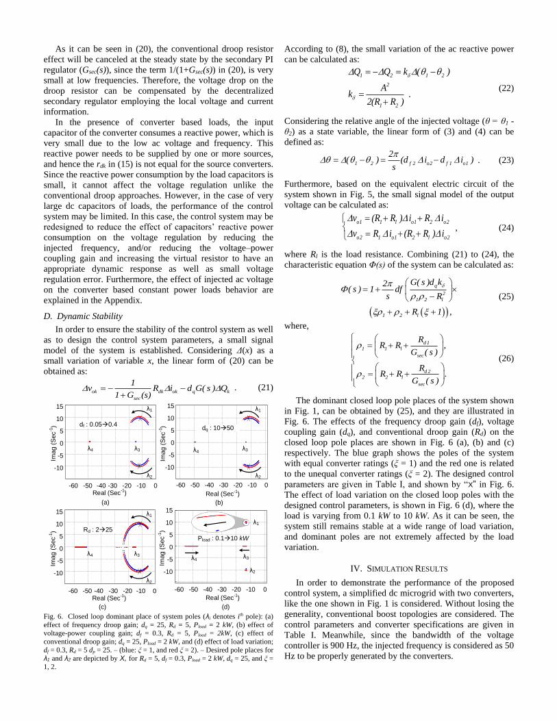
As it can be seen in (20), the conventional droop resistor
effect will be canceled at the steady state by the secondary PI
regulator (Gsec(s)), since the term 1/(1+Gsec(s)) in (20), is very
small at low frequencies. Therefore, the voltage drop on the
droop resistor can be compensated by the decentralized
secondary regulator employing the local voltage and current
information.
In the presence of converter based loads, the input
capacitor of the converter consumes a reactive power, which is
very small due to the low ac voltage and frequency. This
reactive power needs to be supplied by one or more sources,
and hence the rdk in (15) is not equal for the source converters.
Since the reactive power consumption by the load capacitors is
small, it cannot affect the voltage regulation unlike the
conventional droop approaches. However, in the case of very
large dc capacitors of loads, the performance of the control
system may be limited. In this case, the control system may be
redesigned to reduce the effect of capacitors’ reactive power
consumption on the voltage regulation by reducing the
injected frequency, and/or reducing the voltage–power
coupling gain and increasing the virtual resistor to have an
appropriate dynamic response as well as small voltage
regulation error. Furthermore, the effect of injected ac voltage
on the converter based constant power loads behavior are
explained in the Appendix.
D. Dynamic Stability
In order to ensure the stability of the control system as well
as to design the control system parameters, a small signal
model of the system is established. Considering Δ(x) as a
small variation of variable x, the linear form of (20) can be
obtained as:
ok dk ok q k
sec
1v R i d G( s ) Q
1 G (s)
. (21)
-60 -50 -40 -30 -20 -10 0
-10
10
0
5
-5
15
-60 -50 -40 -30 -20 -10 0
-10
10
0
5
-5
15
-60 -50 -40 -30 -20 -10 0
-10
10
0
5
-5
15
Real (Sec-1
) Real (Sec-1
)
Real (Sec-1
)
Imag (
Sec
-1)
Imag (
Sec
-1)
Imag (
Sec
-1)
(a) (b)
(d)
dq : 1050df : 0.050.4
Pload : 0.110 kW
λ1
λ2
λ1
λ2
λ3λ3λ4 λ4
λ4λ3
λ1
λ2
(c)
-60 -50 -40 -30 -20 -10
-10
10
0
5
-5
15
Real (Sec-1
)
Imag (
Sec
-1) Rd : 225
λ1
λ2
λ3λ4
0
Fig. 6. Closed loop dominant place of system poles (λi denotes ith pole): (a)
effect of frequency droop gain; dq = 25, Rd = 5, Pload = 2 kW, (b) effect of
voltage-power coupling gain; df = 0.3, Rd = 5, Pload = 2kW, (c) effect of
conventional droop gain; dq = 25, Pload = 2 kW, and (d) effect of load variation;
df = 0.3, Rd = 5 dp = 25. – (blue: ξ = 1, and red ξ = 2). – Desired pole places for
λ1 and λ2 are depicted by X, for Rd = 5, df = 0.3, Pload = 2 kW, dq = 25, and ξ =
1, 2.
According to (8), the small variation of the ac reactive power
can be calculated as:
1 2 1 2
2
1 2
Q Q k ( )
Ak .
2(R R )
(22)
Considering the relative angle of the injected voltage (θ = θ1 -
θ2) as a state variable, the linear form of (3) and (4) can be
defined as:
1 2 f 2 o2 f 1 o1
2( ) (d i d i )
s
. (23)
Furthermore, based on the equivalent electric circuit of the
system shown in Fig. 5, the small signal model of the output
voltage can be calculated as:
o1 1 l o1 2 o2
o2 1 o1 2 l o2
v (R R ) i R i
v R i (R R ) i
, (24)
where Rl is the load resistance. Combining (21) to (24), the
characteristic equation Φ(s) of the system can be calculated as:
q
2
1 2 l
1 2 l
G( s )d k2( s ) 1 df
s R
R 1 ,
(25)
where,
d 1
1 1 l
sec
d 2
2 2 l
sec
RR R ,
G ( s )
RR R .
G ( s )
(26)
The dominant closed loop pole places of the system shown
in Fig. 1, can be obtained by (25), and they are illustrated in
Fig. 6. The effects of the frequency droop gain (df), voltage
coupling gain (dq), and conventional droop gain (Rd) on the
closed loop pole places are shown in Fig. 6 (a), (b) and (c)
respectively. The blue graph shows the poles of the system
with equal converter ratings (ξ = 1) and the red one is related
to the unequal converter ratings (ξ = 2). The designed control
parameters are given in Table I, and shown by “X” in Fig. 6.
The effect of load variation on the closed loop poles with the
designed control parameters, is shown in Fig. 6 (d), where the
load is varying from 0.1 kW to 10 kW. As it can be seen, the
system still remains stable at a wide range of load variation,
and dominant poles are not extremely affected by the load
variation.
IV. SIMULATION RESULTS
In order to demonstrate the performance of the proposed
control system, a simplified dc microgrid with two converters,
like the one shown in Fig. 1 is considered. Without losing the
generality, conventional boost topologies are considered. The
control parameters and converter specifications are given in
Table I. Meanwhile, since the bandwidth of the voltage
controller is 900 Hz, the injected frequency is considered as 50
Hz to be properly generated by the converters.
Page 7
The effectiveness of the power sharing approach is verified
with three case studies. In Case I, equal converter ratings are
considered, and in Case II, the rating of the second converter
is considered to be two times the first one. In Case III, the
performance of the control system is demonstrated in presence
of a dc motor supplied through a dc/dc converter.
The simulation results of Case I and Case II are depicted in
Fig. 7 and Fig. 8. In both cases, a 1.3 kW and a 1 kW load are
connected at t = 0.5 Sec and t = 2 Sec respectively. As it can
be seen from Fig. 7 (a), the load is equally shared between two
converters and the output current has the same value.
Furthermore, due to the ac signal injection, a small ac ripple is
superimposed onto the dc currents. The instantaneous current
waveform are also illustrated in Fig. 7 (a) at t = 1.3 Sec, where
the 180o phase difference between the ac currents indicates the
ac power flows between the two converters. The voltage
waveforms of the converters shown in Fig. 7 (b), illustrate an
acceptable voltage regulation within the microgrid. The dc
voltage of the converters is settled close to 400 V.
Furthermore, the instantaneous voltage waveforms are shown
at t = 1.3 Sec, with a 2.5 V sinusoidal ripple. The frequency of
the superimposed ac voltage is shown in Fig. 7 (c), where the
frequency is decreased by increasing the load.
Load sharing results between the two converters with
different power ratings are also shown in Fig. 8. As shown in
Fig. 8 (a), the output current of the first converter is two times
that of the second one, since the capacity of the first converter
is two times more than the second one. The output voltage of
the converters is also regulated near to the reference value as
shown in Fig. 8 (b). The variation of the injected frequency is
also shown in Fig. 8 (c).
TABLE I
Specifications of the DC microgrid and control system – ω* = 2πf*.
Definition Symbol Case
I
Case
II
Case
III
Injected frequency f* (Hz) 50 50 50
Frequency-current droop
df1,
df2
df3 (Hz/A)
0.3,
0.3
0.3,
0.6
0.3,
0.3,
0.6
Superimposed ac voltage A (V) 2.5 2.5 2.5
Voltage-power coupling dq (V/VAR) 25 25 25
DC link voltage Vdc (V) 400 400 400
Inner controllers
Voltage
controller 0.45 + 20 /s
Current
controller 0.05 + 2/s
Secondary regulator Voltage
regulator 0.88 + 8.6/s
Loads Pload (kW) 1, 1.3 4
DC
Motor
Mechanical
speed ωm(rad/Sec) 150
Mechanical
torque Tm (Nm) 27
Rotor Inertia J (Nms2) 0.0881
Armature
impedance
Ra (Ω), La(H)
0.57, 0.0046
Field
impedance
Rf (Ω), Lf (H)
190, 0.2
Electrical
Power P (kW) 4
Impedance of line 1 r1+jω*L1 (Ω) 2+j0.0565
Impedance of line 2 r2+jω*L2 (Ω) 1.5+j0.0565
Converter Parameters Ldc (mH) 2
Cdc (μF) 500
Curr
ent (
A)
Voltage
(V
)F
requ
ency (
Hz)
0.5 1.5 3.0
Time (sec)
0 1.0 2.52.048
49
50
350
400
450
0
2
4
6
49.5
49
48.6
Turn on a 1 kW Load
2.5 V
0.08 A
(a)
(b)
(c)
180o
f1f2
3.15 A4.65 A
0.08 A
Turn on a 1.3 kW Load
2.5 V
Fig. 7. Simulation results of Case I (see Table I) with the equal converter
ratings, output current of (a) first and (b) second converters, output voltage of
(c) first and (d) second converters, and (e) injected frequency.
Curr
ent (
A)
Voltage
(V
)F
requ
ency (
Hz)
0.5 1.5 3.0Time (sec)
0 1.0 2.52.048
49
50
350
400
450
0
2
4
8
6
49.33
48.6748.1
(c)
(b)
(a)
f1f2
4.2 A
2.1 A 3.1 A
6.2 A
Turn on a 1 kW Load Turn on a 1.3 kW Load
Fig. 8. Simulation results of Case II (see Table I) with unequal converter
ratings, output current of (a) first and (b) second converters, output voltage of
(c) first and (d) second converters, and (e) injected frequency.
CMDM
LM ω
DC Motor Fig. 9. Block diagram of the simplified dc motor-based constant power load –
CM = 200 μF, LM = 2 mH.
Page 8
Fre
qu
ency (
Hz)
Time (sec)
0
48
49
50
0
Turn on a DC Motor
0.4 1.6 2
Voltage
(V
)
350
400
450
(a)
Curr
ent (
A)
5
10
(c)
47
0.8 1.2
(b)
0.2 0.6 1 1.4 1.8
f1f2
Fig. 10. Simulation results for Case III (see Table I), A 4 kW dc motor-based
constant power load is connected at t = 0.6 Sec, V* = 400 V.
In Case III, a dc motor is connected to the microgrid
through a dc/dc converter shown in Fig. 9. The load and
system parameters are given in Table I. At first, the converters
are supporting a 2.7 kW load. At t = 0.6 Sec, the dc motor as a
constant power load– with 27 Nm and 150 rad/Sec mechanical
load – is connected to the microgrid. The output currents of
converters are shown in Fig. 10(a) implying a proper load
sharing in the presence of a converter-based constant power
load. Furthermore, as shown in Fig. 10(b), the output voltage
of converters is regulated close to the reference value after
connecting the motor. The injected frequencies variations are
also shown in Fig. 10(c).
The simulation results indicate an accurate load sharing
between converters as well as an acceptable voltage regulation
within the microgrid. Both primary and secondary controllers
are employing the local grid information to reach the power
sharing objectives. Further validations by experimental tests
are given in the next section.
V. EXPERIMENTAL RESULTS
In order to further validate the proposed method, some
experimental tests are performed taking into consideration the
load variations as well as equal and unequal converter ratings
and different line impedances. The experimental setup shown
in Fig. 11 contains two conventional boost converters with the
parameters given in Table I. Each converter is controlled by its
own Digital Signal Processor (DSP). The experimental results
are reported in the following.
At first, the same ratings for both converters are
considered, and the performance of the proposed adaptive
droop is compared with the conventional droop method. The
output current and voltage of the converters employing the
conventional droop method are shown in Fig. 12. As it can be
seen from Fig. 12, the output voltage of the converters is not
regulated to the reference value and the load current is not
equally shared between the two converters. Furthermore, by
increasing the load, the output voltage drops and current
mismatches are increased. However, utilizing the proposed
control system gives an accurate current sharing between the
converters as shown in Fig. 13. Moreover, after increasing the
load from 1.2 kW to 1.7 kW, the dc voltages can be properly
regulated close to the reference value, and hence the
performance of the decentralized secondary controller can be
further validated. Moreover, the ac ripple of the voltage and
currents are 2.5 V and 0.1 A respectively.
The experimental results of power sharing for the unequal
converter ratings are illustrated in Fig. 14 and Fig. 15 for In,1 =
0.5 × In,2 and Fig. 16 for In,1 = 2 × In,2. As it can be seen, the
load is accurately shared between the converters and the dc
voltage is properly regulated close to the reference value. As
shown in Fig. 14, the output current of the second converter is
two times that of the first one (R1 = 1.5 Ω, R2 = 2 Ω). After a
load variation at t = 0.5 Sec, the load sharing is still accurately
carried out and the voltage is regulated at the nominal value.
To further evaluate the proposed controller, the line
resistances are changed (i.e., R1 = 2 Ω, R2 = 1.5 Ω), and the
results are shown in Fig. 15, implying an accurate load sharing
and a proper voltage regulation.
Moreover, in the results shown in Fig. 16, the rating of the
converters is changed and the performance of the proposed
controllers are demonstrated in terms of sudden load
reduction. As it can be seen, the output current of the first
converter is two times that of the second one. In addition, the
voltage can be restored after a load variation, and hence, the
decentralized secondary controller can properly carry out the
voltage regulation.
In the next test, the proposed adaptive frequency droop
approach are compared with the frequency droop approach
introduced in [22]. Power sharing between the two converters
employing the frequency droop controller is shown in Fig.
17(a). As it can be seen in Fig. 17(a), the output currents of
converters do not converge and the system is unstable.
However, applying the adaptive frequency droop approach
merged by the virtual resistor can properly control the power
sharing between the two converters as shown in Fig. 17(b).
Finally, the synchronization procedure is shown in Fig. 18,
where the second converter is initially turned on, and at t = 0.1
Sec, the first converter is connected. At t = 0.12 Sec, the PLL
of the first converter extracts the phase of ac voltage and the
second converter, injects the ac voltage. Therefore, both
converters are properly synchronized and the currents are
shared between the converters.
Line - R1
Line - R2Load
Vo1
Vo2
Vin1
Vin2
VPCC
DSP 2
DSP 1
Converter 2
Converter 1
Fig. 11. Photograph of the implemented hardware setup based on two boost
converters Pload = 1.2 + 0.5 kW.
Page 9
Voltage
(V
)
0.2 0.5Time (sec)
0 0.4 0.7
Curr
ent (
A)
2.5
3.5
1.5
0.5
4.5
5.5
400
340
390
380
370
360
350
0.1 0.3 0.6 0.8 0.9 1.0
1.27 A
1.33 A 1.82 A
2.19 A
Io1 Io2
Vo2Vo112 V11.5 V
22 V18 V
Fig. 12. Experimental results of conventional droop approach with equal
converter ratings, In,1 = In,2, Rd1 = Rd2 = 10 Ω, R1 = 2 Ω, R2 = 1.5 Ω, and V* =
400 V.
Curr
ent (A
)
0.2 0.5Time (sec)
0 0.4 0.7
Voltage
(V
)
400
2.5
340
390
380
370
360
350
3.5
1.5
0.5
4.5
5.5
0.1 0.3 0.6 0.8 0.9 1.0
Io1 Io2
Vo2Vo1
1.5 A 2.1 A
2.5 V 0.1 A
Fig. 13. Experimental results of adaptive droop approach with equal
converter ratings, In,1 = In,2, df1 = df2 = 0.3, dq = 25, Rd1 = Rd2 = 5 Ω, R1 = 2 Ω,
R2 = 1.5 Ω, and V* = 400 V.
0.2 0.5Time (sec)
0 0.4 0.7
Curr
ent (
A)
Voltage
(V
)
2.5
3.5
1.5
0.5
4.5
5.5400
340
390
380
370
360
350
0.1 0.3 0.6 0.8 0.9 1.0
Io1 Io2
Vo2
Vo1
2 A
1 A
2.8 A
1.4 A
Fig. 14. Experimental results of adaptive droop approach with unequal
converter ratings, In,1 = 0.5 × In,2, df1 = 2 × df2 = 0.6, dq = 25, Rd1 = 2 × Rd2 = 10
Ω, R1 = 2 Ω, R2 = 1.5 Ω, and V* = 400 V.
0.4 1.0Time (sec)
0 0.8 1.4
Curr
ent (
A)
Voltage
(V
)
2.5
3.5
1.5
0.5
4.5
5.5400
340
390
380
370
360
350
0.2 0.6 1.2 1.6 1.8 2.0
Io1 Io2
Vo2
Vo1
2 A
1 A
2.8 A
1.4 A
Fig. 15. Experimental results of adaptive droop approach with unequal
converter ratings, In,1 = 0.5 × In,2, df1 = 2 × df2 = 0.6, dq = 25, Rd1 = 2 × Rd2 = 10
Ω, R1 = 1.5 Ω, R2 = 2 Ω, and V* = 400 V.
Voltage
(V
)
0.2 0.5Time (sec)
0 0.4 0.7
Curr
ent (
A)
2.5
3.5
1.5
0.5
4.5
5.5
400
340
390
380
370
360
350
0.1 0.3 0.6 0.8 0.9 1.0
Io1Io2
Vo2
Vo1
2 A
1 A
2.8 A
1.4 A
Fig. 16. Experimental results of adaptive droop approach with unequal
converter ratings, In,1 = 2 × In,2, df1 = 0.5 × df2 = 0.3, dq = 25, Rd1 = 0.5 × Rd2 =
5 Ω, R1 = 1.5 Ω, R2 = 2 Ω, and V* = 400 V.
Voltage
(V
)
0.1 0.25
Time (sec)
0 0.2 0.35
Curr
ent (
A)
2.5
3.5
1.5
0.5
4.5
5.5
400
340
390
380
370
360
350
0.05 0.15 0.3 0.4 0.45 0.5
Io1
Io2
Vo2
Vo1
Voltage
(V
)
0.4 1.0
Time (sec)
0 0.8 1.4
Curr
ent (
A)
2.5
3.5
1.5
0.5
4.5
5.5
400
340
390
380
370
360
350
0.2 0.6 1.2 1.6 1.8 2.0
Io1Io2
Vo2
Vo1
(a)
(b) Fig. 17. Experimental results of (a) frequency droop control in [22], (b)
adaptive droop approach, In,1 = In,2, df1 = df2 = 0.3, dq = 25, Rd1 = Rd2 = 5 Ω, R1
= 0 Ω, R2 = 1.5 Ω, and V* = 400 V.
Voltage
(V
)
0.2 0.5
Time (sec)
0 0.4 0.7
Curr
ent (
A)
2.5
3.5
1.5
0.5
4.5
5.5
400
340
390
380
370
360
350
0.1 0.3 0.6 0.8 0.9 1.0
Io1
Io2
Vo2
Vo1
Connecting the 1st converter
Synchronizing both converters
Fig. 18. Experimental results of Synchronization of the adaptive droop
approach with equal converter ratings, In,1 = In,2, df1 = df2 = 0.3, dq = 25, Rd1 =
Rd2 = 5 Ω, R1 = 1.5 Ω, R2 = 2 Ω, and V* = 400 V.
VI. CONCLUSION
In this paper, an adaptive droop controller is presented for
the primary and secondary power sharing in LVDC microgrids
based on a superimposed frequency. Both the primary and
secondary layers fulfill the power sharing objectives by
utilizing the local voltage, current and superimposed
frequency information without employing an extra
communication network, which implies a higher reliability
compared to the communication-based power sharing
approaches. The output current of the converters are
accurately proportional to the rated current of converters, and
output voltage of converters are regulated close to the
reference value. The small signal model of the suggested
control system for a simplified dc microgrid is obtained and its
stability is analyzed in order to design the control parameters.
The viability of the proposed control approach is ensured for
equal and unequal DG ratings and different line impedances as
well as for resistive and constant power loads. The proposed
approach is verified by simulations and experimental tests.
APPENDIX
EFFECT OF SUPERIMPOSED AC VOLTAGE ON DC LOADS
In this section, the effect of the superimposed ac voltage on
dc loads are studied by employing the dynamic model of
Page 10
loads. Modeling different types of loads is out of scope of this
paper, hence the most common loads of a dc grid, i.e.,
constant power loads (converter-based) are considered in this
section. The dynamic model of a dc/dc converter can be
shown as Fig. 19 with double voltage and current regulators,
where Gv(s) and Gi(s) are the voltage and current controllers,
Gvg(s), Gvd(s), Gid(s) and Gig(s) are the input to output, control
to output, input to inductor current and control to inductor
current transfer functions [37]. The transfer functions
modeling the converter dynamic behavior are presented in
[37].
In order to show the effect of the ac ripple superimposed to
the input voltage, the closed loop transfer function from the
input to output voltage (or inductor current) should be
analyzed. From Fig. 19, the closed loop input voltage (Vin) to
output voltage (Vout) transfer function (H(s)) can be calculated
as:
ig i
vg
i id vd
v i vd i id
G G+G
(1+G G )G( )
1
=G G G /(1+G G )
out
in L
L
VH s
V T
T
. (27)
Gv(s)Vout
Dynamic Model of
Converter
Gi(s) Gvd(s)
Gvg(s)
Gid(s)
Gig(s)
Vout
IL
Vin
*
Current
Regulator
Voltage
Regulator
duty
Input voltage
Output voltage
Inductor
current
Fig. 19. Dynamic model and control block diagram of a dc/dc converter with
voltage and current regulators.
1
Mag
nitu
de
(dB
)
100
Frequency (Hz)
0
-50
-100
-150
101
90
0
-90
-180Ph
ase
(D
eg
)
102
103
104
105
10-1
10-2
50 Hz
-35 dB
Fig. 20. Input to output transfer function (Vout/Vin) of a dc/dc buck converter –
Ldc = 2 mH, Cdc = 500 μF, Pout = 2 kW, Vin = 400 V, Vout = 200 V, Gv(s) = 5 +
20/s and Gi(s) = 0.1 + 1/s.
Mag
nitu
de
(dB
)
100
Frequency (Hz)
50
-50
-100
-150
101
90
0
-90
-180
Ph
ase
(D
eg
)
102
103
104
105
10-1
10-2
50 Hz
-24 dB
0
-270
Fig. 21. Input to output transfer function (Vout/Vin) of a dc/dc boost converter –
Ldc = 2 mH, Cdc = 500 μF, Pout = 2 kW, Vin = 400 V, Vout = 550 V, Gv(s) = 2 +
20/s and Gi(s) = 0.05 + 1/s.
According to [37], the loop transfer function TL(s) causes
small gains at low frequencies. Therefore, the effect of input
voltage ripple on the system dynamics will be rejected by the
closed loop control system. For instance, H(s) is shown in
frequency domain for a conventional buck and boost
converters in Fig. 20 and Fig. 21 respectively. The amplitude
of H(s) is very small at low frequencies, and for example, at
50 Hz, it is –35 dB for buck and –24 dB for boost converter.
Therefore, at low frequencies, the effect of input voltage ripple
and disturbances can be rejected by the closed loop control
system. Moreover, the superimposed ac voltage in this paper is
very small, i.e., 2.5 V, and it cannot affect the load dynamic
behavior.
REFERENCES
[1] B. T. Patterson, “DC, Come Home: DC Microgrids and the Birth of
the ‘Enernet,’” IEEE Power Energy Mag., vol. 10, no. 6, pp. 60–69,
2012.
[2] D. Boroyevich, I. Cvetkovic, R. Burgos, and D. Dong, “Intergrid: A
Future Electronic Energy Network?,” IEEE J. Emerg. Sel. Top.
Power Electron., vol. 1, no. 3, pp. 127–138, 2013.
[3] P. Fairley, “DC Versus AC: The Second War of Currents Has
Already Begun [In My View],” IEEE Power Energy Mag., vol. 10,
no. 6, pp. 104–103, Nov. 2012.
[4] V. Nasirian, A. Davoudi, F. L. Lewis, and J. M. Guerrero,
“Distributed Adaptive Droop Control for Dc Disribution Systems,”
IEEE Trans. Energy Convers., vol. 29, no. 4, pp. 944–956, 2014.
[5] S. Moayedi and A. Davoudi, “Distributed Tertiary Control of DC
Microgrid Clusters,” IEEE Trans. Power Electron., vol. 31, no. 2,
pp. 1717–1733, 2015.
[6] Q. Shafiee, T. Dragicevic, J. C. Vasquez, and J. M. Guerrero,
“Hierarchical Control for Multiple DC-Microgrids Clusters,” IEEE
Trans. Energy Convers., vol. 29, no. 4, pp. 922–933, 2014.
[7] T. Dragicevic, J. M. Guerrero, J. C. Vasquez, and D. Skrlec,
“Supervisory Control of an Adaptive-Droop Regulated DC
Microgrid with Battery Management Capability,” IEEE Trans.
Power Electron., vol. 29, no. 2, pp. 695–706, 2014.
[8] S. Anand, B. G. Fernandes, and J. M. Guerrero, “Distributed
Control to Ensure Proportional Load Sharing and Improve Voltage
Regulation in Low-Voltage DC Microgrids,” IEEE Trans. Power
Electron., vol. 28, no. 4, pp. 1900–1913, 2013.
[9] J. M. Guerrero, J. C. Vasquez, J. Matas, L. G. De Vicuña, and M.
Castilla, “Hierarchical Control of Droop-Controlled AC and DC
Microgrids - A General Approach toward Standardization,” IEEE
Trans. Ind. Electron., vol. 58, no. 1, pp. 158–172, 2011.
[10] S. Peyghami, H. Mokhtari, and F. Blaabjerg, “Hierarchical Power
Sharing Control in DC Microgrids,” in Microgrid: Advanced
Control Methods and Renewable Energy System Integration, First.,
Magdi S Mahmoud, Ed. Elsevier Science & Technology, 2017, pp.
63–100.
[11] S. Peyghami-Akhuleh, H. Mokhtari, P. C. Loh, and F. Blaabjerg,
“Distributed Secondary Control in DC Microgrids with Low-
Bandwidth Communication Link,” in Proc IEEE PEDSTC, 2016,
pp. 641–645.
[12] D. Chen, L. Xu, and L. Yao, “DC Voltage Variation Based
Autonomous Control of DC Microgrids,” IEEE Trans. Power
Deliv., vol. 28, no. 2, pp. 637–648, 2013.
[13] A. Khorsandi, M. Ashourloo, and H. Mokhtari, “A Decentralized
Control Method for a Low-Voltage DC Microgrid,” IEEE Trans.
Energy Convers., vol. 29, no. 4, pp. 793–801, 2014.
[14] D. Chen and L. Xu, “Autonomous DC Voltage Control of a DC
Microgrid with Multiple Slack Terminals,” IEEE Trans. Power
Syst., vol. 27, no. 4, pp. 1897–1905, Nov. 2012.
[15] X. Lu, J. M. Guerrero, K. Sun, and J. C. Vasquez, “An Improved
Droop Control Method for DC Microgrids Based on Low
Bandwidth Communication With DC Bus Voltage Restoration and
Enhanced Current Sharing Accuracy,” IEEE Trans. Power
Electron., vol. 29, no. 4, pp. 1800–1812, Apr. 2014.
[16] D. Perreault, R. Selders, and J. Kassakian, “Frequency-Based
Current-Sharing Techniques for Paralleled Power Converters,”
IEEE Trans. Power Electron., vol. 13, no. 4, pp. 626–634, 1998.
Page 11
[17] M. Angjelichinoski, C. Stefanovic, P. Popovski, H. Liu, P. C. Loh,
and F. Blaabjerg, “Multiuser Communication through Power Talk in
DC MicroGrids,” IEEE J. Sel. Areas Commun., vol. 34, no. 7, pp.
2006–2021, Jul. 2015.
[18] T. Dragičević, J. Guerrero, and J. C. Vasquez, “A Distributed
Control Strategy for Coordination of an Autonomous LVDC
Microgrid Based on Power-Line Signaling,” IEEE Trans. Ind.
Electron., vol. 61, no. 7, pp. 3313–3326, 2014.
[19] A. Tuladhar, H. Jin, T. Unger, and K. Mauch, “Control of Parallel
Inverters in Distributed AC Power Systems with Consideration of
Line Impedance Effect,” IEEE Trans. Ind. Appl., vol. 36, no. 1, pp.
131–138, 2000.
[20] A. Tuladhar, H. Jin, T. Unger, and K. Mauch, “Parallel Operation of
Single Phase Inverter Modules with No Control Interconnections,”
in Proc. IEEE APEC, 1997, vol. 1, pp. 94–100.
[21] A. Tuladhar and H. Jin, “A Novel Control Technique to Operate
DC/DC Converters in Parallel with No Control Interconnections,” in
Proc. IEEE PESC, 1998, vol. 1, pp. 892–898.
[22] S. Peyghami, H. Mokhtari, P. C. Loh, P. Davari, and F. Blaabjerg,
“Distributed Primary and Secondary Power Sharing in a Droop-
Controlled LVDC Microgrid with Merged AC and DC
Characteristics,” IEEE Trans. Smart Grid, pp. 1–1, 2016.
[23] S. Peyghami, P. Davari, H. Mokhtari, P. C. Loh, and F. Blaabjerg,
“Synchronverter-Enabled DC Power Sharing Approach for LVDC
Microgrids,” IEEE Trans. Power Electron., pp. 1–1, 2016.
[24] Q. Shafiee, J. M. Guerrero, and J. C. Vasquez, “Distributed
Secondary Control for Islanded Microgrids—A Novel Approach,”
IEEE Trans. Power Electron., vol. 29, no. 2, pp. 1018–1031, 2014.
[25] T.-F. Wu, Y.-K. Chen, and Y.-H. Huang, “3C Strategy for Inverters
in Parallel Operation Achieving an Equal Current Distribution,”
IEEE Trans. Ind. Electron., vol. 47, no. 2, pp. 273–281, Apr. 2000.
[26] G. Ding, F. Gao, S. Zhang, P. C. Loh, and F. Blaabjerg, “Control of
Hybrid AC / DC Microgrid under Islanding Operational
Conditions,” J. Mod. Power Syst. Clean Energy, vol. 2, no. 3, pp.
223–232, 2014.
[27] N. Hatziargyriou, H. Asano, R. Iravani, and C. Marnay,
“Microgrids,” IEEE Power Energy Mag., vol. 5, no. 4, pp. 78–94,
2007.
[28] X. Lu, J. M. Guerrero, K. Sun, J. C. Vasquez, R. Teodorescu, and L.
Huang, “Hierarchical Control of Parallel AC-DC Converter
Interfaces for Hybrid Microgrids,” IEEE Trans. Smart Grid, vol. 5,
no. 2, pp. 683–692, 2014.
[29] J. M. Guerrero, L. Hang, and J. Uceda, “Control of Distributed
Uninterruptible Power Supply Systems,” IEEE Trans. Ind.
Electron., vol. 55, no. 8, pp. 2845–2859, 2008.
[30] J. Rocabert, A. Luna, F. Blaabjerg, and P. Rodriguez, “Control of
Power Converters in AC Microgrids,” IEEE Trans. Power
Electron., vol. 27, no. 11, pp. 4734–4749, 2012.
[31] M. Karimi-Ghartemani, “Universal Integrated Synchronization and
Control for Single-Phase DC/AC Converters,” IEEE Trans. Power
Electron., vol. 30, no. 3, pp. 1544–1557, 2015.
[32] S. Khongkhachat, “Hierarchical Control Strategies in AC
Microgrids,” 2015.
[33] P. C. Loh, D. Li, Y. K. Chai, and F. Blaabjerg, “Autonomous
Control of Interlinking Converter with Energy Storage in Hybrid
AC-DC Microgrid,” IEEE Trans. Ind. Appl., vol. 49, no. 3, pp.
1374–1382, 2013.
[34] Q. Zhong and G. Weiss, “Synchronverters: Inverters That Mimic
Synchronous Generators,” IEEE Trans. Ind. Electron., vol. 58, no.
4, pp. 1259–1267, Apr. 2011.
[35] H. Nikkhajoei and R. Iravani, “Steady-State Model and Power Flow
Analysis of Electronically-Coupled Distributed Resource Units,”
IEEE Power Eng. Soc. Gen. Meet. PES, vol. 22, no. 1, pp. 721–728,
Jan. 2007.
[36] J. M. Guerrero, L. GarciadeVicuna, J. Matas, M. Castilla, and J.
Miret, “Output Impedance Design of Parallel-Connected UPS
Inverters With Wireless Load-Sharing Control,” IEEE Trans. Ind.
Electron., vol. 52, no. 4, pp. 1126–1135, Aug. 2005.
[37] R. Erickson and D. Maksimovic, “Fundamentals of Power
Electronics,” Second. New York: Kluwer, 2001.
Saeed Peyghami (S’14) was born in
Tabriz, Iran, in 1988. He received the B.Sc.
and M.Sc. degrees both in electrical
engineering from the Department of
Electrical Engineering, Sharif University of
Technology, Tehran, in 2010 and 2012,
respectively. He is currently working
toward the Ph.D. degree in electrical
engineering at Sharif University of
Technology, Tehran, Iran.
His research interests include power electronics system
control, power quality, application of power electronics in
distributed power systems.
Hossein Mokhtari (M’03–SM’14) was
born in Tehran, Iran, on August 19, 1966.
He received the B.Sc. degree in electrical
engineering from Tehran University,
Tehran, in 1989. He received the M.Sc.
degree in power electronics from the
University of New Brunswick,
Fredericton, NB, Canada, in 1994, and the
Ph.D. degree in power electronics/power
quality from the University of Toronto, Toronto, ON, Canada
in 1999.
From 1989 to 1992, he worked in the Consulting Division
of Power Systems Dispatching Projects, Electric Power
Research Center Institute, Tehran. Since 2000, he has been
with the Department of Electrical Engineering, Sharif
University of Technology, Tehran, where he is currently a
Professor. He is also a Senior Consultant to several utilities
and industries.
Frede Blaabjerg (S’86–M’88–SM’97–
F’03) was with ABB-Scandia, Randers,
Denmark, from 1987 to 1988. From 1988
to 1992, he was a Ph.D. Student with
Aalborg University, Aalborg, Denmark.
He became an Assistant Professor in 1992,
Associate Professor in 1996, and Full
Professor of power electronics and drives
in 1998. His current research interests
include power electronics and its applications such as in wind
turbines, PV systems, reliability, harmonics and adjustable
speed drives.
He has received 17 IEEE Prize Paper Awards, the IEEE
PELS Distinguished Service Award in 2009, the EPE-PEMC
Council Award in 2010, the IEEE William E. Newell Power
Electronics Award 2014 and the Villum Kann Rasmussen
Research Award 2014. He was an Editor-in-Chief of the IEEE
TRANSACTIONS ON POWER ELECTRONICS from 2006
to 2012. He is nominated in 2014 and 2015 by Thomson
Reuters to be between the most 250 cited researchers in
Engineering in the world.


![Reliability demonstration test for load-sharing systems with exponential … · load-sharing systems are studied in [21–23]. Though load-sharing plays an important role in system](https://static.documents.pub/doc/80x56/61277d39a5fd5c5284375127/reliability-demonstration-test-for-load-sharing-systems-with-exponential-load-sharing.jpg)


