17
1 PURPOSE PURPOSE APPENDIX B APPENDIX B ROAD RESERVE ROAD RESERVE REQUIREMENTS REQUIREMENTS

1PURPOSE PURPOSE
APPENDIX BAPPENDIX BROAD RESERVEROAD RESERVEREQUIREMENTSREQUIREMENTS
Document History and Version Control:Document History and Version Control: Version 1.1Document Contact:Document Contact: Development & Infrastructure
NOTE:NOTE:These requirements shall take precedence from the time of adoption and will be applied retrospectively.
DOCUMENT CONTROL
VersionVersion Date AprovedDate Aproved Approved ByApproved By DescriptionDescription1.0 - - Creation of Original Document
1.1 July 2015 Manager,Development & Infrastructure
Release of Document
APPENDIX B: ROAD RESERVE REQUIREMENTSAPPENDIX B: ROAD RESERVE REQUIREMENTS

CONTENTSCONTENTSDESIGN RESPONSIBILITIES 3
TRAFFIC MANAGEMENT 4
ROAD GEOMETRY 5
TYPICAL STREETSCAPE - LANEWAY 6
TYPICAL STREETSCAPE - LOCAL ROAD 7
TYPICAL STREETSCAPE - COLLECTOR ROAD 8
TYPICAL STREETSCAPE - COLLECTOR ROAD W/ CENTRAL MEDIAN 9
ROAD PAVEMENT 10
FOOTPATHS, KERBING & DRAINAGE 12
DRIVEWAYS 14
PUBLIC LIGHTING 15
SERVICES 16
DESIGN RESPONSIBILITIES
Road layout and connection to existing Council roads shall be designed and constructed in accordance with the following guidelines:
• ‘AUSTROADS publication – Guide to road design, Part 2: Design Considerations’
• ‘AUSTROADS publication – Guide to road design, Part 3: Geometric design’
• ‘AUSTROADS publication – Guide to pavement technology, Part 2: Pavement structural design’
• ‘APRG21: A guide for the design of new pavements for light traffic’
• ‘AS 1289: Methods of testing soils for engineering purposes’
• AS 3798 Guidelines on earthworks for commercial and residential developments
• ‘DPTI’s Pavement Marking Manual’
• ‘DPTI’s Standard Specification for Excavation and Reinstatement of Road Pavements’
• ‘DPTI’s specification for roadwork’s’
• ‘AS 1743 Road Signs Specification’
• ‘AS 1742 Manual of Uniform Traffic Control Devices’
• ‘AS 1158 Lighting for Roads and Public Spaces’
• ‘AS 2890 Parking Facilities’
• AS 1428 Design for Access and Mobility
• AS 4282 Control of the obtrusive effects of outdoor lighting
• ‘DPTI Manual of Legal Responsibilities and Technical Requirements for Traffic Control Devices Part 2: Code of Technical Requirements’
• ‘Council Standard Details’
1.11.1All newly created developments are to be serviced by a road network that is under the care and control of Council. These roads are to be located within road reserves and shall comply with Council requirements.
1.21.2A system of roads for each development is to be endorsed by Council in line with Councils adopted road reserve hierarchy prior to Development Application approval. The choice of road reserve from the hierarchy will be informed by traffic volumes. The road layout is to include local area traffic management in order to regulate the vehicle movements within the road network.
1.31.3If the interface of a proposed road is with a Department of Planning, Transport and Infrastructure (DPTI) maintained road then the developer must consult with DPTI to seek their written comments and approval.
1.41.4Appropriate landscape initiatives for all Road Reserves include, but are not restricted to the following:
a) Street trees, refer to Council’s endorsed species list
b) Shrub planting (no turf ), refer to Council’s endorsed species list
c) Use of upright kerbs adjacent reserves in all circumstances other than pram ramps and driveways, unless otherwise arranged with Council Landscape Architect or Land Development Engineer
1.51.5WSUD principles form an integral component of road reserves, from both a functional and aesthetic perspective and should be incorporated where applicable and to Council standards
1.61.6All road vertical and horizontal geometry is to be in accordance with the AUSTROADS guidelines.
4DESIGN RESPONSIBILITIESDESIGN RESPONSIBILITIES
APPENDIX B: ROAD RESERVE REQUIREMENTSAPPENDIX B: ROAD RESERVE REQUIREMENTS

TRAFFIC MANAGEMENT
2.12.1The detailed design of all footpaths, roads and open spaces and other public areas must comply with the requirements of the Disability Discrimination Act
2.22.2The traffic management plan to be provided will include appropriate traffic signage, line marking, street nameplate locations, street name kerb etching, and location and type of traffic control devices, in accordance with AS 1742 and DPTI Code of Technical Requirements
2.32.3Line marking is to be marked in accordance with AS 1742 and DPTI Pavement Marking Manual and specifications. The line marking is to have 2 coats of paint with reflective beading and not applied earlier than 7 days after bitumen has been laid
2.42.4One on street parking space (minimum) shall be provided per allotment. For higher density developments a parking plan shall be provided. Street parking will be required in the vicinity of courtyard and villa allotments
2.52.5Street blade signs and pole are to be installed in accordance with Councils standard detail. Street name signs shall be erected at the Developer’s expense within two months of completion of construction of roads. The Council will not permit the installation of street signs on street light poles.
2.62.6In addition to the standard name plate on post, the street name will be etched on the kerb face at the intersection in upper case Arial 80mm and painted black with white reflective lettering.
2.72.7Formal Car parks and any traffic control devices must be designed and constructed in accordance with current AS 2890.1 Off-Street Car parking, current AS 1742 Manual of Uniform Traffic Control Devices and the Notice to Council (Part 1 & 2) under the current Road Traffic Act 1961 from the Minister for Transport.
5TRAFFIC MANAGEMENTTRAFFIC MANAGEMENT
APPENDIX B: ROAD RESERVE REQUIREMENTSAPPENDIX B: ROAD RESERVE REQUIREMENTS

ROAD GEOMETRY
3.13.1All roads are to be free draining to ensure no water ponds within the road carriageway. All cross grades are to be at least 1% and the longitudinal grade of the road is to be no less than 0.5%
3.23.2In accordance with the City of Playford Development Plan, new roads to be vested to Council including collector roads are to be designed for a 50km/hr speed environment (with the exception of designated shared priority pedestrian/vehicular road)
3.33.3In general, local roads should be a maximum length of 150 metres without having an un-signalised intersection, speed control device or speed reducing bend
INTERSECTIONSINTERSECTIONS
3.43.4The road network layout should provide appropriate junctions throughout the development. They are to be located sufficient distances apart in order to separate traffic movements, avoid traffic banking and provide reasonable intervals for drivers to make decisions. The recommended spacing’s for intersections are;
a) 60 metres if intersections are located on the same side of through street
b) 40 metres if the intersections are located on opposite sides of the through street
3.53.5The layout, geometry of intersections and sight distance restrictions are to be in accordance with ‘Austroads Part 6: Intersections, Interchanges and Crossings’.
3.63.6All signalised intersections and Pedestrian/Rail Crossings must be designed in accordance with Council Requirements and DPTI standards and guidelines and constructed to DPTI Master Specifications. Intersections are to be approved by DPTI prior to construction.
3.73.7All intersections are to free draining to ensure no water ponds within the intersection. All cross grades are to be at least 1% and the longitudinal grade of the intersection is to be no less than 0.5%
STOPPING DISTANCESSTOPPING DISTANCES
3.83.8All roads shall be designed to ensure safe stopping sight distance based on the most severe case of the following parameters:
a) Crests - twice the stopping distance measured between eye heights 1.15 metres above the carriageway.
b) Driveways - 1.15 metre eye height to 0.6 metre tail light height.
c) Intersections - twice the stopping distance measured between eye heights 1.15 metres above the carriageway.
3.93.9Stopping distance should be based on the estimated 85th percentile vehicle speeds. Note that it may be necessary to undertake substantial earthworks or provide traffic control devices to achieve the minimum requirements.
3.103.10Corner cut-off shall be minimum 4500mm x 4500mm.
6ROAD GEOMETRYROAD GEOMETRY
APPENDIX B: ROAD RESERVE REQUIREMENTSAPPENDIX B: ROAD RESERVE REQUIREMENTS

7TYPICAL STREETSCAPE - LANEWAYTYPICAL STREETSCAPE - LANEWAY
TYPICAL STREETSCAPE - LANEWAY
DESIGN REQUIREMENTSDESIGN REQUIREMENTS
4.14.16.5 metre wide road reserve width (minimum)
4.24.2Rear loading laneways are to be a 6.5 metre wide sealed carriageway, which may extend from property boundary to property boundary.
4.34.3No on street parking within laneways is allowed and yellow line marking shall be used accordingly.
4.44.4Laneways are not to be designed as a thoroughfare, but should only provide access to immediately adjoining dwellings. They are to be connected between two roads in a straight line with a maximum length of 90 metres
4.54.5All laneways must be designed to accommodate refuse vehicles and emergency services vehicles.
4.64.6Interconnecting laneways, T-configurations and right hand bends are not permitted.
4.74.7Include protuberances to accommodate lighting which do not exceed 1 metre.
4.84.8Include landscaping treatment in accordance with the Landscape Architect Approval.
APPENDIX B: ROAD RESERVE REQUIREMENTSAPPENDIX B: ROAD RESERVE REQUIREMENTS
FIGURE 4.1 - Laneway Cross Section
APPENDIX B: ROAD RESERVE REQUIREMENTSAPPENDIX B: ROAD RESERVE REQUIREMENTS
8TYPICAL STREETSCAPE - LOCAL ROADTYPICAL STREETSCAPE - LOCAL ROAD
TYPICAL STREETSCAPE - LOCAL ROAD
DESIGN REQUIREMENTSDESIGN REQUIREMENTS
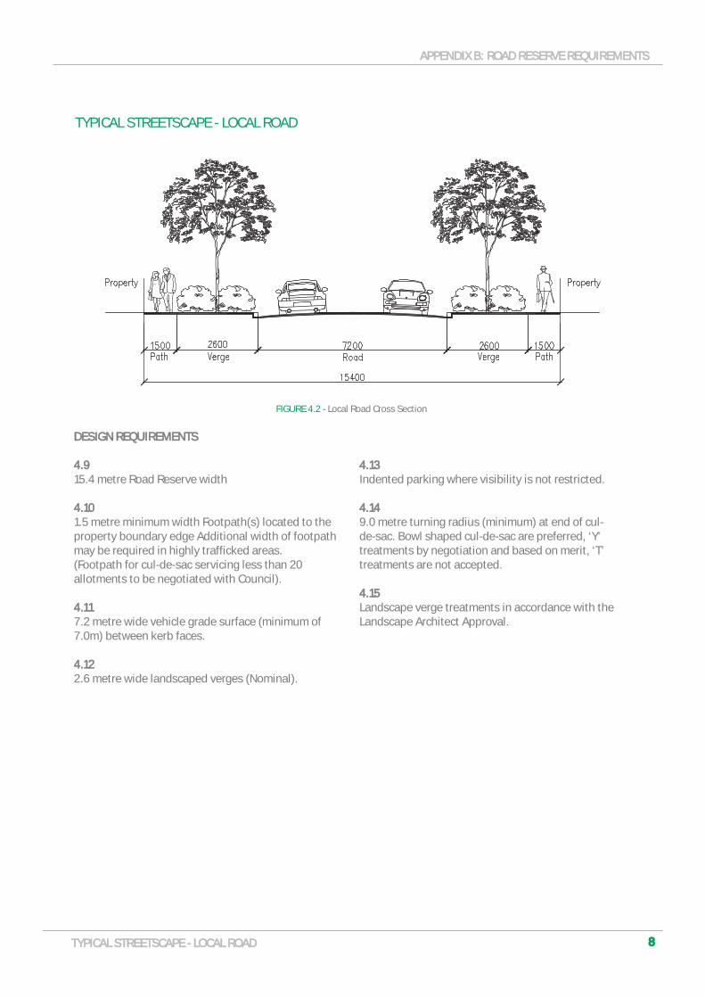
4.94.915.4 metre Road Reserve width
4.104.101.5 metre minimum width Footpath(s) located to the property boundary edge Additional width of footpath may be required in highly trafficked areas. (Footpath for cul-de-sac servicing less than 20 allotments to be negotiated with Council).
4.114.117.2 metre wide vehicle grade surface (minimum of 7.0m) between kerb faces.
4.124.122.6 metre wide landscaped verges (Nominal).
4.134.13Indented parking where visibility is not restricted.
4.144.149.0 metre turning radius (minimum) at end of cul-de-sac. Bowl shaped cul-de-sac are preferred, ‘Y’ treatments by negotiation and based on merit, ‘T’ treatments are not accepted.
4.154.15Landscape verge treatments in accordance with the Landscape Architect Approval.
FIGURE 4.2 - Local Road Cross Section
APPENDIX B: ROAD RESERVE REQUIREMENTSAPPENDIX B: ROAD RESERVE REQUIREMENTS
9TYPICAL STREETSCAPE - COLLECTOR ROADTYPICAL STREETSCAPE - COLLECTOR ROAD
TYPICAL STREETSCAPE - COLLECTOR ROAD
DESIGN REQUIREMENTSDESIGN REQUIREMENTS
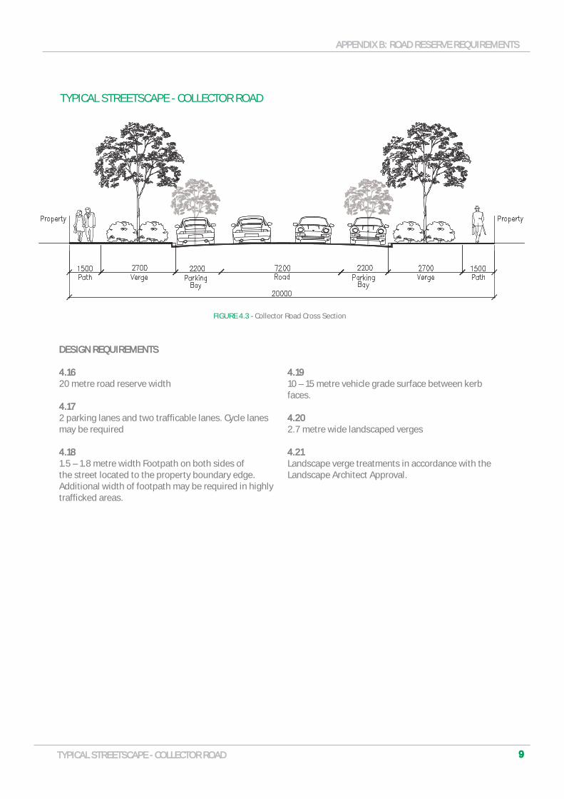
4.164.1620 metre road reserve width
4.174.172 parking lanes and two trafficable lanes. Cycle lanes may be required
4.184.181.5 – 1.8 metre width Footpath on both sides of the street located to the property boundary edge. Additional width of footpath may be required in highly trafficked areas.
4.19 4.19 10 – 15 metre vehicle grade surface between kerb faces.
4.20 4.20 2.7 metre wide landscaped verges
4.214.21Landscape verge treatments in accordance with the Landscape Architect Approval.
FIGURE 4.3 - Collector Road Cross Section
APPENDIX B: ROAD RESERVE REQUIREMENTSAPPENDIX B: ROAD RESERVE REQUIREMENTS
1010TYPICAL STREETSCAPE - COLLECTOR ROAD W/CENTRAL MEDIANTYPICAL STREETSCAPE - COLLECTOR ROAD W/CENTRAL MEDIAN
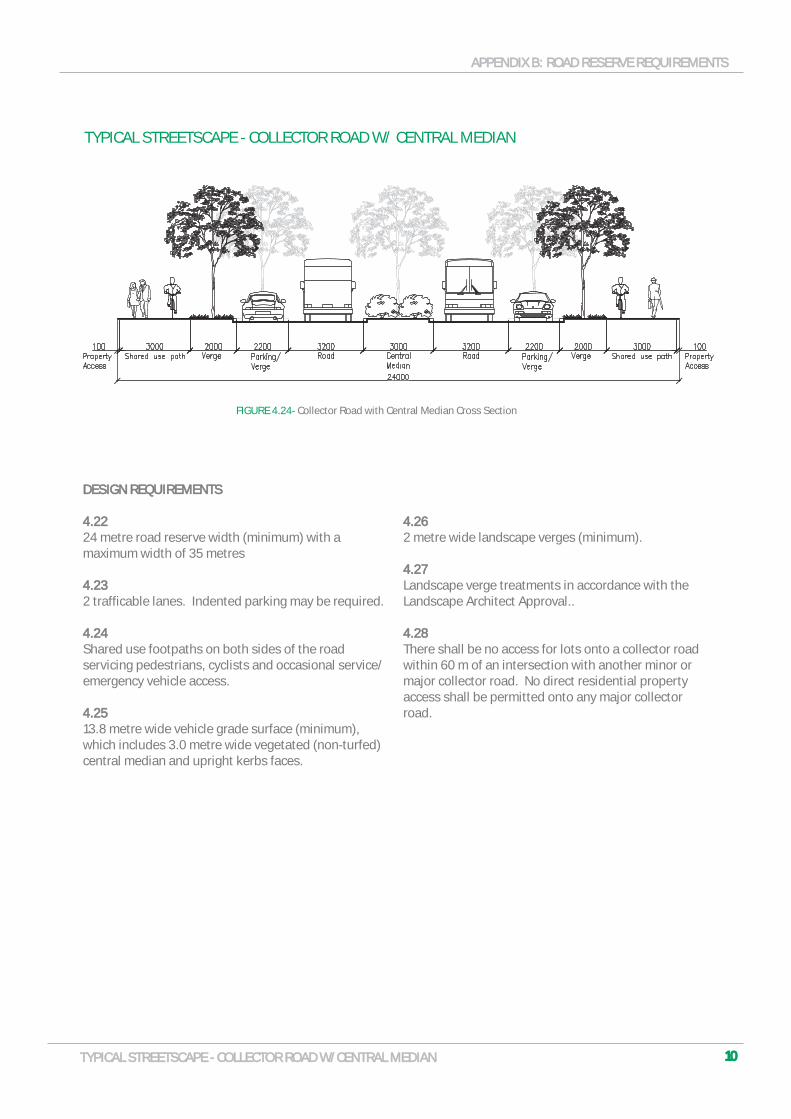
TYPICAL STREETSCAPE - COLLECTOR ROAD W/ CENTRAL MEDIAN
DESIGN REQUIREMENTSDESIGN REQUIREMENTS
4.224.2224 metre road reserve width (minimum) with a maximum width of 35 metres
4.234.232 trafficable lanes. Indented parking may be required.
4.24 4.24 Shared use footpaths on both sides of the road servicing pedestrians, cyclists and occasional service/emergency vehicle access.
4.254.2513.8 metre wide vehicle grade surface (minimum), which includes 3.0 metre wide vegetated (non-turfed) central median and upright kerbs faces.
4.264.262 metre wide landscape verges (minimum).
4.274.27Landscape verge treatments in accordance with the Landscape Architect Approval..
4.28 4.28 There shall be no access for lots onto a collector road within 60 m of an intersection with another minor or major collector road. No direct residential property access shall be permitted onto any major collector road.
FIGURE 4.24- Collector Road with Central Median Cross Section

ROAD PAVEMENT
According to the classification of the road as stated in Section 3 above the road designer shall as part of the design provide the expected Equivalent Standard Axles (ESA’s) according to lots served, buses, refuse trucks, emergency vehicles etc.
Road pavements are to be designed in accordance with AUSTROADS guidelines, and to the satisfaction of Council. The pavement design will be determined by CBR testing of the subgrade material, consideration of environmental effects and traffic loading. All testing is to be carried out through a NATA registered laboratory.
The design life of the road should be for:
a) Local Roads 20yr minimumb) Collector Roads 30yr minimumc) Rigid Pavements 40yr minimum
The excavation and filling of land must be undertaken in accordance with specifications approved by Council. Those specifications shall comply with AS3798-1990 – “Guidelines for Earth Works B Commercial and Residential Development”.
Geotechnical documentation is to be provided to Council demonstrating that filling complies with the requirements of AS2879-1998-Residential Services Footing Code All pavement design is to allow for construction traffic associated with the development and future works/ stages.
Footpaths are to be constructed on the verges adjacent the property boundary in accordance with streetscape layouts shown.
The subgrade and granular layers are to achieve compaction in accordance with Australian Standards. Each layer is to achieve the required compaction prior to the laying of the next layer. As the compaction tests may take time to undertake, Council can undertake a proof roll as a visual inspection that each layer has achieved the required compaction.
ROAD PAVEMENT TYPESROAD PAVEMENT TYPES
5.15.1The City of Playford has 4 types of Road Pavements:
a) Granular asphalt pavementb) Deep lift asphalt pavementc) Concrete Pavementd) Block Pavers
GRANULAR ASPHALT PAVEMENTGRANULAR ASPHALT PAVEMENT
5.2 5.2 Unless otherwise agreed with Council the sub-base and base course shall be compacted in layers no greater than 200mm thick to the following compaction:
a) Sub Grade to be compacted to achieve 98% standard compaction to AS 1289
b) Sub Base to be compacted to achieve 95% maximum modified to AS 1289
c) Base Course to be compacted to achieve 98% maximum modified to AS 1289
5.35.3Trenches to be compacted in 200mm thick layers to achieve 95% maximum modified to AS 1289
5.45.4All materials for the Sub Base and Base course are to be in accordance with DPTI Specification 215
5.55.5All minor collector roads, residential roads and access roads are to be surfaced with a minimum AC10 asphaltic concrete. All major collector roads, intersections and roundabouts are to be surfaced with a minimum AC14 Asphaltic Concrete.
5.65.6The granular materials are to be sourced from quarries and recycled quarry material is not be used for
1111ROAD PAVEMENTROAD PAVEMENT
APPENDIX B: ROAD RESERVE REQUIREMENTSAPPENDIX B: ROAD RESERVE REQUIREMENTS
DEEP LIFT ASPHALT PAVEMENTDEEP LIFT ASPHALT PAVEMENT
5.75.7Typical Deep lift asphalt pavements are to be constructed in accordance with:
a) ‘AUSTROADS publication – Guide to pavement technology, Part 2: Pavement structural design’
b) ‘APRG21: A guide for the design of new pavements for light traffic’
c) DPTI Specification 215
5.85.8Consideration of compaction requirements shall be given to deep lift layers. Unless agreed with Council Deep Lift pavements shall not be used in residential areas due to the vibration during construction.
5.95.9The granular materials are to be sourced from quarries and recycled quarry material is not be used
CONCRETE PAVEMENTCONCRETE PAVEMENT
5.105.10Typical concrete pavements are to be constructed in accordance with ‘AUSTROADS publication – Guide to pavement technology, Part 2: Pavement structural design’
5.11 5.11 A full jointing layout is to be submitted as a part of the design
5.12 5.12 Materials are to be sourced from quarries and recycled uarry material is not be used.
BLOCK PAVERSBLOCK PAVERS
5.135.13Unless otherwise agreed with Council the sub-base and base course shall be compacted in layers no greater than 200mm thick to the following compaction:
a) Sub Grade to be compacted to achieve 98% standard compaction to AS 1289
b) Sub Base to be compacted to achieve 95% maximum modified to AS 1289
c) Base Course to be compacted to achieve 98% maximum modified to AS 1289
5.14 5.14 Trenches to be compacted in 200mm thick layers to achieve 95% maximum modified to AS 1289
5.155.15All materials for the Sub Base and Base course are to be in accordance with DPTI Specification 215
5.16 5.16 Concrete Block Pavers shall be 80mm thick, Grade N45 with a minimum abrasion resistance of 1.2m at 28 days and interlocking in design. Pavers to be laid on to the compacted road base and embedded on to a minimum 30mm thick compacted bedding sand. Bedding sand shall comply with Part 215 of DTEI specification, sand type A (PM 64). Sand to be free of contaminates likely to cause efflorescence.
5.17 5.17 The bedding materials are to be sourced from quarries and recycled quarry material is not be used
1212ROAD PAVEMENTROAD PAVEMENT
APPENDIX B: ROAD RESERVE REQUIREMENTSAPPENDIX B: ROAD RESERVE REQUIREMENTS
FOOTPATHS, KERBING & DRAINAGE
6.16.1Footpaths are to be located in accordance with the typical streetscape sections shown in Section 3. The falls and grades on footpaths are to be in accordance with Australian Standards AS 1428 and are to be DDA compliant.
6.26.2Minimum footpath widths are to be typically 1.5m and Shared paths to have a minimum width of 3m
6.36.3The cross fall slope is to be a minimum of 2% and maximum 2.5%.
6.46.4Maximum and minimum grades are to match that of the road pavement.
6.56.5The City of Playford has 3 types of footpaths
a) Granular asphalt footpaths/ shared pathsb) Block paversc) Concrete footpath (exposed aggregate or
broom finished)
GRANULAR ASPHALT / SHARED FOOTPATHSGRANULAR ASPHALT / SHARED FOOTPATHSRefer to Standard Detail(s)
6.66.6Base Course to be 80mm compacted PM2 quarry rubble
6.76.730mm compacted depth of AC7 nominal size asphalt
6.86.8Edges to have 30mm compacted dolomite rubble edge
BLOCK PAVER FOOTPATHBLOCK PAVER FOOTPATHRefer to Standard Detail(s)
6.96.9Subgrade to be compacted to 98% MDD
6.106.10Base Course to be 100mm PM2 compacted to 96% MDD
6.116.11Bedding sand to be minimum 30mm thick and compacted. Sand to be free of contaminates likely to cause efflorescence.
6.126.12Concrete block pavers to be 80mm thick interlocking pavers.
CONCRETE FOOTPATHSCONCRETE FOOTPATHSRefer to Standard Detail(s) 6.136.13Subgrade to be compacted to 96% MDD to a depth of 100mm
6.146.14Base course to be 150mm PM2 compacted to 98% MDD
6.156.15Minimum slab thickness to be 100mm using grade 32MPa concrete. Slab to be reinforced with SL72 mesh. Mesh to be placed centrally with a minimum 50mm cover to the edges.
6.166.16Expansion joists are to be to be provided at every third evenly spaced tooled joint.
1313FOOTPATHS, KERBING & DRAINAGEFOOTPATHS, KERBING & DRAINAGE
APPENDIX B: ROAD RESERVE REQUIREMENTSAPPENDIX B: ROAD RESERVE REQUIREMENTS
EXPOSED AGGREGATE FOOTPATHS EXPOSED AGGREGATE FOOTPATHS Refer to Standard Detail(s)
6.176.17Subgrade to be compacted to 98% STD to a depth of 100mm
6.186.18Subbase to be 150mm PM2/20 compacted to 95% MDD
6.196.19Minimum slab thickness to be 100mm using grade 32MPa concrete. Slab to be reinforced with SL72 mesh. Mesh to be placed centrally with a minimum 50mm cover to the edges.
6.20 6.20 Minimum slab thickness across driveways to be 125mm.
6.216.21Expansion joists are to be to be provided at every third evenly spaced tooled joint and where footpath abuts kerbing, ramps, pits, covers or other objects that extend into footpath.
6.22 6.22 Provide dowel bars at all pram ramp interfaces; embed 150mm, grease and cap at one end.
PRAM RAMPS PRAM RAMPS Refer to Standard Detail(s)
6.236.23Pram ramps are to be provided at all crossing points regardless of kerb type and are to be poured integrally to the kerb.
6.246.24Tactile surface indicators shall be installed to AS1428.4. See Council Standard Detail SD03 – SD06
KERBING AND DRAINAGEKERBING AND DRAINAGERefer to Standard Detail(s)
6.256.25Typically concrete kerbs/ kerbs and gutters shall be barrier kerbs (as shown on Council Standard Details SD01) 6.26 6.26 In low density residential areas, the use of Rollover kerbs (as shown on Council Standard Detail SD02) shall only be used following discussion and agreement with Council.
6.27 6.27 All collector roads and roads adjacent reserves are to have vertical barrier kerbs 150mm min unless agreed otherwise with Council. In general Finished Floor Levels are to be 300mm above the top of kerb fronting the building.
6.28 6.28 Drainage from a development into the water table should be via a chequer plate drain or 100mm diameter pipe encased in concrete Chequer plate drain or piped drain dimensions and materials are to be in accordance with Council Standard Detail SD01 – SD03.
6.296.29Drainage to water table shall terminate at an approved galvanised steel kerb adaptor in accordance with Council’s standard detail.
6.30 6.30 Spoon drains to be in accordance with Council Standard Details SD01
6.31 6.31 An access driveway must be constructed to provide a minimum 150 mm high barrier to the flow of water from the kerb invert to the property boundary.
1414FOOTPATHS, KERBING & DRAINAGEFOOTPATHS, KERBING & DRAINAGE
APPENDIX B: ROAD RESERVE REQUIREMENTSAPPENDIX B: ROAD RESERVE REQUIREMENTS

DRIVEWAYS
Refer to Standard Detail(s)
7.17.1Minimum width of driveway crossover to be 3m for a single driveway and 5m for a double driveway. Refer to standard details.
7.27.2Maximum crossfall across footpath to be 2.5%.
7.37.3Base to be 100mm PM2 quarry rubble compacted to 96% MDD on a compacted subbase. All driveways shall be sealed with an approved durable material such as concrete, bricks or asphalt. Material is to match the existing footpath.
7.4 7.4 Minimum slab thickness
a) For residential - 125mm thick, 25MPa Concrete slab reinforced with SL62 mesh placed centrally with a minimum 50mm cover at ends.
b) For commercial – 150mm thick, 32MPa Concrete slab reinforced with SL92 mesh placed centrally with a minimum 50mm cover at ends.
7.57.5Driveway to be located a minimum distance of 1000mm from an SEP and other services.
7.67.6Rubble entranceways are to be used in rural areas only and are to consist of 100mm compacted rubble on a compacted subbase.
1515DRIVEWAYSDRIVEWAYS
APPENDIX B: ROAD RESERVE REQUIREMENTSAPPENDIX B: ROAD RESERVE REQUIREMENTS
PUBLIC LIGHTING
In accordance with the Development Plan The development should provide lighting in frequently used public spaces in order to allow for safe passage of vehicles and pedestrians alike and around public facilities such as toilets, telephones, bus stops, seating, litter bins, automatic tellers, taxi ranks and carparks. The network also conveys public utilities to service allotments for which the service have regulated authority operate with the road reserve space.
7.17.1All public lighting is to comply with lighting code AS 1158 and comply with Information on SAPN Utilities Standard Tariff Public Lighting Arrangements NICC – 403 The proposed lighting is to use SAPN standard poles and fittings. The developer shall submit the lighting design and SAPN ‘Agreement to the SAPN extension and the street lighting installations’ form NICC-451 for approval by the Council.
7.27.2The lighting levels for laneways, minor and major roads is to be in accordance with AS 1158 ‘Lighting for roads and public space’ part 3.1 Pedestrian area (Category P). The lighting level is to satisfy the conditions set out in sub-category P4.
7.37.3The lighting levels for collector roads is to be in accordance with AS 1158 ‘Lighting for roads and public space’ part 1.1 Vehicular traffic (Category V). The lighting level is to satisfy the conditions set out in sub-category V5.
7.47.4The light poles are to be situated minimum 1.0 m from back of kerb as the footpath. Common service trench (including Telstra pits etc) will be minimum 1.0 m from the back of kerb.
7.57.5Where existing footpaths are located behind back of kerb, light poles will be situated minimum 1.5 m from back of kerb. Common service trench (including Telstra pits etc.) will be minimum 1m from back of kerb.
7.67.6As a part of the lighting design the engineer is to supply a layout plan showing the coverage of lighting and isolux levels generated.
1616PUBLIC LIGHTINGPUBLIC LIGHTING
APPENDIX B: ROAD RESERVE REQUIREMENTSAPPENDIX B: ROAD RESERVE REQUIREMENTS

SERVICES
7.17.1Services provided to the allotments within the development will be approved by the relevant authority, including but not limited to:
a) Electrical distribution to be approved by SAPNb) Communications to be approved by Telstrac) Potable water and sewer to be approved by SA
Waterd) Third pipe systems to be modelled and
approved by SA Water. A separate meter is required for each allotment.
e) Broadband pit and pipe where applicable
7.27.2New services that are laid in an existing road for a service authority by a third party contractor are to be in accordance with councils trenching policy.
7.37.3In accordance with the Development Plan: Infrastructure; Principles of development control, new electrical services being installed within verges should be located underground and to the kerb edge of the verge. When located in a development’s open space contribution, above ground service box locations and access shall be located to minimise the visual intrusion of open space from dwellings, including site entrances, vistas and access points.
7.47.4Tree root barriers should be installed a minimum 750mm radius of newly planted trees (measured from the trunk of the tree) from new services or to the extents of the established tree canopies. New services should not be installed within a minimum 750mm radius of newly planted trees. New services should not be installed in the root protection zone of recognised significant trees.
1717SERVICESSERVICES
APPENDIX B: ROAD RESERVE REQUIREMENTSAPPENDIX B: ROAD RESERVE REQUIREMENTS


