1 Presented to AASHTO T‐8, June 13, 2017 AASHTO AS 13‐0024 Support for the HSCOBS Technical Committee on Moveable Bridges (T-8) in a Technical Advisory Role for Specification Updates – Span Lock Design Study By James M. Phillips III, PE Hardesty & Hanover, Tampa, FL
Transcript
1
Presented to AASHTO T‐8, June 13, 2017
AASHTO AS 13‐0024Support for the HSCOBS Technical Committee on Moveable Bridges (T-8) in a Technical Advisory Role for Specification Updates – Span Lock Design Study
By James M. Phillips III, PEHardesty & Hanover, Tampa, FL
2
Double‐Leaf Bascule BridgeSpan Locks
STUDY TEAM Hardesty & Hanover, LLC
• Jim Phillips, PE – Research Lead• Rafal Wuttrich, PE – Lead Finite Element Modeling
• Steve Mikucki, PE – Peer Review AECOM (formerly URS and E.C. Driver & Associates, Inc.)• Jim Englert, PE – Project Manager• Michael Reponen, PE – Finite Element Modeling
• FDOT• Will Potter, PE ‐ Structures Research – Field Instrumentation and Testing
• District One & District Four Staff – Support and Bridge Access
AGENDA
Review of Study Purpose & Limitations Recommended Revisions to the AASHTO LRFD Movable Highway Bridge Design Specifications:• Dynamic Load Allowance for Span Lock Design
• Edge Loading / Contact Stresses in Span Lock Design
Expand AASHTO Movable, Article 2.4.1.2, Dynamic Load Allowance, to add the following:
“2.4.1.2.5 Span Locks
The span locks of double‐leaf bascule bridges (center locks) shall be proportioned for full live load plus twice the normal live load dynamic load allowance, specified in Article 3.6.2 of the AASHTO LRFD Bridge Design Specifications.”To further clarify the application of this provision to the fatigue limit state, add the
following commentary:
“C2.4.1.2.5
The use of twice the normal live load dynamic allowance for span locks applies to Strength, Service and Fatigue Limit States.”
SPAN LOCK CONTACT STRESSES
21
Primary Objective: Quantify the effects of bascule span deflection and end rotation on span lock component contact stresses
Methodology: Assess structural deformations that influence contact stresses
Use Finite Element Model (LUSAS) to evaluate contact stresses in load shoes (aka wear plates) and lock bars
Model Hillsborough Avenue bridge and span lock system
Validate model by comparing predicted with measured field strains
Model various load shoe shapes and evaluate performance
STRUCTURAL DEFORMATIONS ‐ GIRDER ROTATION AT THE SPAN LOCKS
22
Sunrise Bridge Tests Included Measurement of End Rotations (Relative Slope Between Leaves)
For the Test Load in the Lane Adjacent to the Instrumented Lock/Girder Relative End Rotation Measured 0.0047 in/in for Static Loading and 0.0053 to 0.0080 in/in for Dynamic Loading
The Calculated Equivalent Slope at a Center Joint for:• Deflection of L/800 = 0.008 in/in• Deflection of L/1000 = 0.006 in/in
Relative Slope
L
Δ
STRUCTURAL DEFORMATIONS ‐ GIRDER ROTATION AT THE SPAN LOCKS
23
Summary of Rotation at Center Joint (1000th inch/inch)Sunrise Blvd. Bridge Load Tests
Test Static/Dynamic Load Position Load Shoe Condition Slope18OSR1 Static Outside Lane Tight Contact all four LLS 4.718OSR2 Static Outside Lane Tight Contact all four LLS 4.718OSR3S Static Outside Lane 0.040” Shim NE LLS, 0.015” gap under SE LLS 4.518OSR4S Static Outside Lane 0.040” Shim SE LLS, 0.015” gap under NE LLS 5.018O301 Dynamic Outside Lane Tight Contact all four LLS 5.318O302 Dynamic Outside Lane Tight Contact all four LLS 6.618O303 Dynamic Outside Lane Tight Contact all four LLS 8.018O304 Dynamic Outside Lane Tight Contact all four LLS 6.118O305S Dynamic Outside Lane 0.040” Shim NE LLS, 0.015” gap under SE LLS 6.318O306S Dynamic Outside Lane 0.040” Shim SE LLS, 0.015” gap under NE LLS 6.3
STRUCTURAL DEFORMATIONS – ECCENTRIC LOADING
24
Table 5 – Comparison of Guide and Receiver Strains (Microstrain)Sunrise Blvd. Bridge Load Tests
Compound shape, Flat Center, Radius front and back: 24 ksi contact stress Limited eccentric loading Potential for additional optimization
18“R
RECOMMENDED CHANGES TO AASHTO LRFD MOVABLEAdd the following to Article 6.8.1.5.1, Locking Devices of the AASHTO Movable:
Contact surfaces for span locks shall be designed and detailed to minimize edge loading that may occur due to the deformation of the supporting structure under vehicular loading.
Provide a minimum ½” radius on the leading and trailing edges of contact surfaces subject to edge loading.
Providing a radius on one or more of the contact surfaces should be considered where other means are not available to relieve edge loading.
RECOMMENDED CHANGES TO AASHTO, CONTINUEDAdd commentary for Article 6.8.1.5.1 Locking Devices:
Contact surfaces for span lock systems include wear plates or bushings in the guides and receivers of lock bar type span locks, jaw and diaphragm castings, forgings or shoes, and similar components that function to transfer the load across a joint through a contact stress.
Under the influence of live load, movable spans deflect and the end(s) of the span(s) at the location of locking devices rotates.
For double‐leaf bascule bridges the end rotations of adjacent leaves are additive in relative effect and therefore more significant than for single‐leaf bascule bridges.
RECOMMENDED CHANGES TO AASHTO, CONTINUEDAdd commentary for Article 6.8.1.5.1 Locking Devices:
If the lock system is attached eccentrically to the main longitudinal members, such as on a cantilevered bracket, additional torsional deflection or rotation could take place. If these deformations are not accounted for, edge loading and eccentric loading of the lock system and supports will result in significant restraint and corresponding structural effects.
Typical clearances provided between lock components (e.g. lock bar and receiver bushing) may be considered in determining the magnitude and effect of edge loading.
Bushings supported on multiple springs that allow the bushing to rotate with the contacting surface, may provide relief from edge loading.
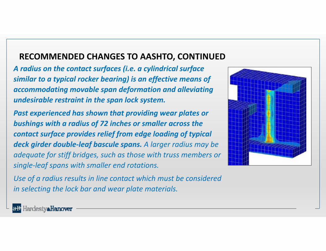
RECOMMENDED CHANGES TO AASHTO, CONTINUEDA radius on the contact surfaces (i.e. a cylindrical surface similar to a typical rocker bearing) is an effective means of accommodating movable span deformation and alleviating undesirable restraint in the span lock system.
Past experienced has shown that providing wear plates or bushings with a radius of 72 inches or smaller across the contact surface provides relief from edge loading of typical deck girder double‐leaf bascule spans. A larger radius may be adequate for stiff bridges, such as those with truss members or single‐leaf spans with smaller end rotations.
Use of a radius results in line contact which must be considered in selecting the lock bar and wear plate materials.
RECOMMENDED CHANGES TO AASHTO, CONTINUED
Additional consideration and analysis may be warranted if a double‐leaf bascule is expected to carry rail traffic as the tolerances for rail alignment may be more stringent than that required for highway or pedestrian traffic.
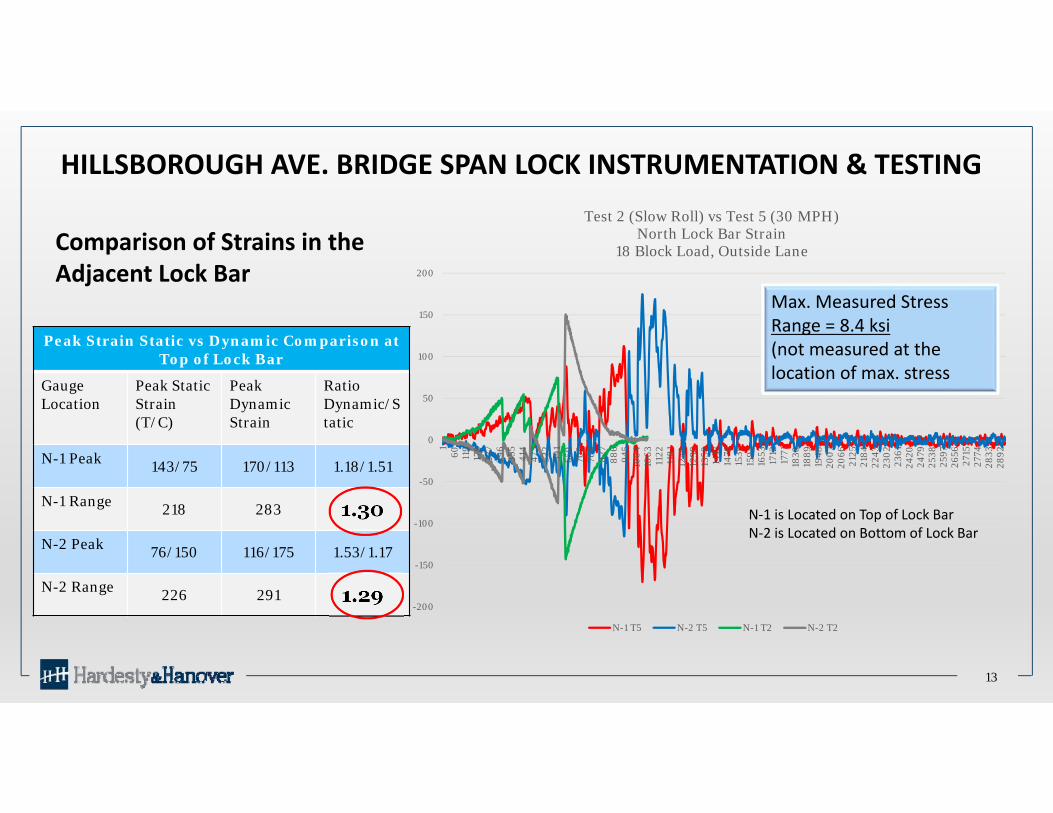
Comparison of Center Joint Deflections (inches)Hillsborough Ave. Bridge Load Tests
Lock / Load Location
18 Block Truck 30 Block Truck
Static Load Dynamic Load Ratio Static Load Dynamic Load Ratio
North Lock / Adjacent Lane
0.09 0.12 1.31 0.11 0.13 1.20
South Lock / Adjacent Lane
0.08 0.13 1.61 0.11 0.14 1.35
North Lock / Far Lane
0.07 0.12 1.79 0.07 0.12 1.64
South Lock / Far Lane
0.06 0.11 1.89 0.08 0.14 1.88
OTHER KEY FINDINGS OF PROJECT
34
Wear of lock components (load shoes or wear plates) results in a general reduction in span lock effectiveness & performance• Measurable increases in differential deflection• Measurable but relatively small changes in strain
WEAR EFFECTS ON LOAD TRANSFER AND LOCK PERFORMANCE
35
Simulated Wear Results on Hillsborough Ave Bridge: Measurable Decrease in Effectiveness of the Locks
Relatively Small Decrease in Lock Bar Strain for Typical Wear (8 to 9%)
Up to 25% Decrease in Lock Bar Strain for Excessive Wear
Significant Increase in Differential Deflection ‐350
‐300
‐250
‐200
‐150
‐100
‐50
0
50
100
150
1 38 75 112
149
186
223
260
297
334
371
408
445
482
519
556
593
630
667
704
741
778
815
852
889
926
963
1000
1037
1074
1111
1148
1185
1222
1259
1296
1333
1370
1407
1444
1481
Strain in M
icroStrain / De
flection inch x 100
0
Time Interval
Chart GComparison of Strain & Differential Deflection For Varying Forward
Guide Clearances at North Lock Bar30 Block Load, Slow Rolling / Hillsborough Ave. Bridge
Strain No Adjust Strain 0.042 Shim Strain 0.130 Shim
Defl No Shim Defl 0.042 Shim Defl 0.140 Shim
WEAR EFFECTS ON LOAD TRANSFER
36
Comparison of Maximum Strain Range in the Lock Bar with Shim RemovalHillsborough Ave. Load Tests
(30 Block Truck Load for All Cases)
Lock / Load Location
Clearance at Top Shoe of Forward Guide of North Lock
0.011” 0.052” 0.140”
StrainDynamic Ratio
StrainDynamic Ratio
StrainDynamic Ratio
North Lock / North Lane 429 1.41 383 1.37 334 1.32
South Lock / North Lane 285 2.61 274 2.54 250 2.36
Poorly Shimmed Lock resulted in a measurable (8-9%) but relatively small
reduction Strain in Lock Bar
OTHER KEY FINDINGS OF PROJECT
37
Improper Adjustment of Live Load Shoes (aka Live Load Bearings) can have a measurable effect on span lock and main girder strains but relatively small Increase in strain in main girders and span lock components
EFFECT OF LIVE LOAD SHOE SHIMMING
38
Improper Adjustment or Wear of Live Load Shoe Simulated by Inserting a 0.040” Shim Under NE Load Shoe
Table 6 – Comparison of Maximum Range of Strain for Various Live Load Shoe Shim Adjustments
Sunrise Blvd. Bridge Tests
Load Type
Load Position
LLS Condition+(Shim) ‐(Gap)Inch x 10‐3
MicroStrainNorth East Girder Live Load Shoe
Lock Bar @ Center Joint
North West Girder Live Load Shoe
NE SETop of Bar
Bott. of Bar
StaticOutside Lane
0 0 119 109 98 138
StaticOutside Lane
+40 ‐15 129 113 103 134
DynamicOutside Lane
0 0 169 137 123 183
DynamicOutside Lane
+40 ‐15 201 145 128 213
StaticMiddle Lane
0 0 70 65 59 87
StaticMiddle Lane
+40 ‐15 81 69 67 83
DynamicMiddle Lane
0 0 136 102 90 166
DynamicMiddle Lane
+40 ‐15 153 104 93 167
StaticInside Lane
0 0 30 25 22 38
StaticInside Lane
+40 ‐15 34 24 23 33
DynamicInside Lane
0 0 67 63 56 74
DynamicInside Lane
+40 ‐15 69 66 60 66
NE NW
SWSE
0.040” Shim
0.015” Gap
Instrumented Span Lock
Inside Lane
Outside Lane
Poorly Shimmed Live Load Shoe resulted in a measurable (6%) but relatively small Increase
in Strain in the Lock Bar
EFFECT OF LIVE LOAD SHOE SHIMMING
39
Improper Adjustment or Wear of Live Load Shoe Simulated by Inserting a 0.040” Shim Under SE Load Shoe
Table 6 – Comparison of Maximum Range of Strain for Various Live Load Shoe Shim Adjustments
Sunrise Blvd. Bridge Tests
Load Type
Load Position
LLS Condition+(Shim) ‐(Gap)Inch x 10‐3
MicroStrainNorth East Girder Live Load Shoe
Lock Bar @ Center Joint
North West Girder Live Load Shoe
NE SETop of Bar
Bott. of Bar
StaticOutside Lane
0 0 119 109 98 138
StaticOutside Lane
‐15 +40 120 103 94 138
DynamicOutside Lane
0 0 169 137 123 183
DynamicOutside Lane
‐15 +40 186 141 123 193
StaticMiddle Lane
0 0 70 65 59 87
StaticMiddle Lane
‐15 +40 74 66 59 86
DynamicMiddle Lane
0 0 136 102 90 166
DynamicMiddle Lane
‐15 +40 146 110 92 164
StaticInside Lane
0 0 30 25 22 38
StaticInside Lane
‐15 +40 30 23 23 33
DynamicInside Lane
0 0 67 63 56 74
DynamicInside Lane
‐15 +40 70 73 65 91
NE NW
SWSE0.040” Shim
0.015” Gap
Instrumented Span Lock
Poorly Shimmed Live Load Shoe resulted in a measurable (8%) but relatively small Increase
in Strain in the Main Girders
Questions?
40
DYNAMIC EFFECTS
AASHTO Table 3.6.2.1‐1, Dynamic Load Allowance, IM
Components IM
Deck Joints – All Limit States 75%
All Other Components
Fatigue and Fracture Limit State
All Other Limit States
15%
33%
Article 2.4.1.2.4, End Floorbeams, of AASHTO Movable states:
“The end floorbeams of the moving span shall be proportioned for full factored live load plus twice the normal dynamic load allowance specified in Article 3.6.2 of the AASHTO LRFD Bridge Design Specifications.”
Article 6.8.1.5.1, Locking Devices, of AASHTO Movable states:
“Double leaf spans shall be provided with center locks to lock together the toe ends of the spans and tail locks or latches. Center locks shall transfer live load and impact from on leaf to the other.”