44
AASHTO Design and Material Specification Changes LRFD BDS Section 6, Various Articles Karl H. Frank Consultant NSBA

AASHTO Design and Material Specification
ChangesLRFD BDS Section 6, Various Articles
Karl H. Frank
Consultant
NSBA

Bolts
2

ASTM SpecificationsHigh Strength Bolts
• New Specification Combines 4 Specifications into 1 for both buildings and bridges-F3125
– A325 Standard Hex Bolt
– F1852 (A325 Tension Control)
– A490 Standard Hex Bolt
– F2280 (A490 Tension Control)
– + Metric
• The old names become Grades
3
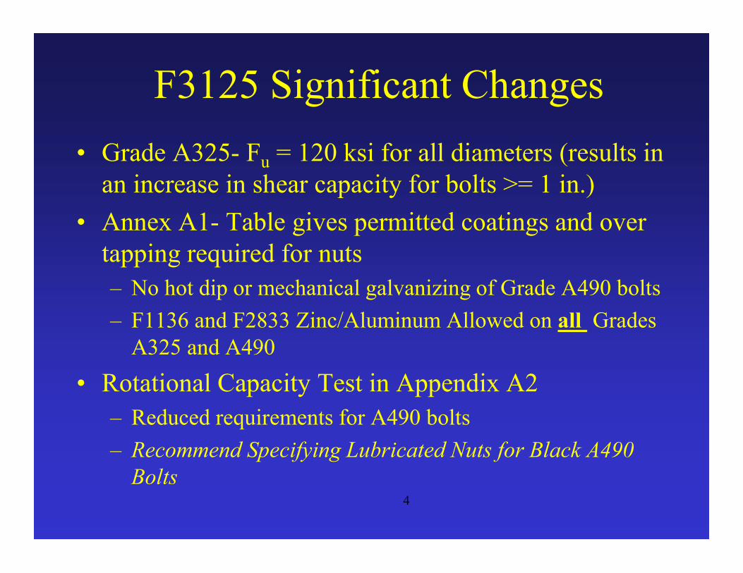
F3125 Significant Changes
• Grade A325- Fu = 120 ksi for all diameters (results in an increase in shear capacity for bolts >= 1 in.)
• Annex A1- Table gives permitted coatings and over tapping required for nuts
– No hot dip or mechanical galvanizing of Grade A490 bolts
– F1136 and F2833 Zinc/Aluminum Allowed on all Grades A325 and A490
• Rotational Capacity Test in Appendix A2
– Reduced requirements for A490 bolts
– Recommend Specifying Lubricated Nuts for Black A490 Bolts
4

AASHTO LRFD Changes
• Bolt Shear Strength
• Slip Critical Categories
• Standard Hole Sizes
• Girder Field Splice Design
KHF
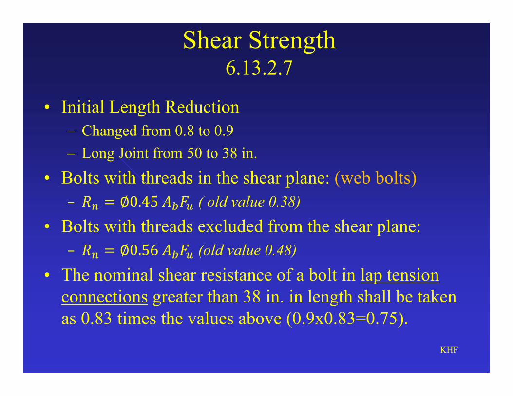
Shear Strength 6.13.2.7
• Initial Length Reduction
– Changed from 0.8 to 0.9
– Long Joint from 50 to 38 in.
• Bolts with threads in the shear plane: (web bolts)
– �� = ∅0.45 ���� ( old value 0.38)
• Bolts with threads excluded from the shear plane:
– �� = ∅0.56 ���� (old value 0.48)
• The nominal shear resistance of a bolt in lap tension connections greater than 38 in. in length shall be taken as 0.83 times the values above (0.9x0.83=0.75).
KHF
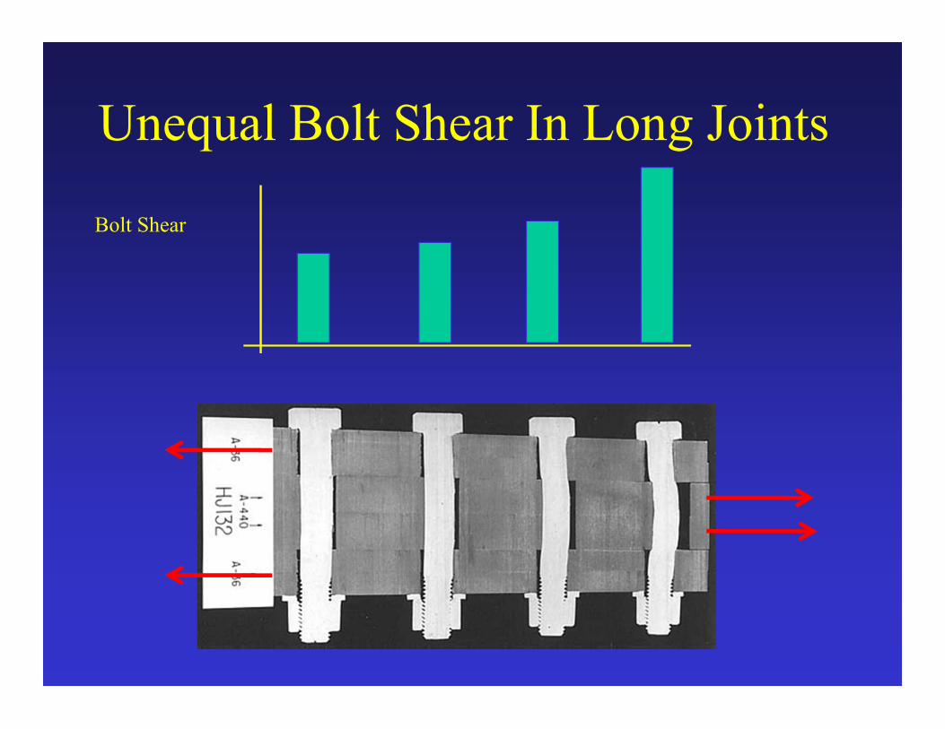
Unequal Bolt Shear In Long Joints
Bolt Shear
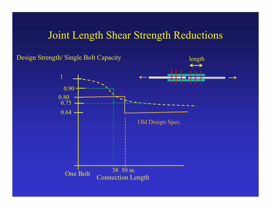
Joint Length Shear Strength Reductions
Design Strength/ Single Bolt Capacity
Connection Length38 50 in.
1
0.80
0.64
Old Design Spec.
One Bolt
0.90
length
0.75

Bolt Shear StrengthConnection Length <= 38 in.
Threads Not Excluded from Shear Plane“N” Bolt
Threads Excluded from Shear Plane“X” Bolt
Fs=0.80
Shear Strength:0.9 x 0.62 x F� x A����
0.56 x F� x A����
Shear Strength:0.9 x 0.62 x F� x �. � A����
0.45 x F� x A����

utensile
t
F x A x 0.70
Strength Tensile x 0.70P
Tension InstalledBolt
Pt
ts shn PN K KRCapacity Slip
Kh= Hole Factor= 1 (normal size holes)
Ks= Surface Condition Slip Coefficient=0.5(blasted or Zinc Rich)
Ns=Number of Slip Planes per Bolt
Fs=1.0(Art.6.13.2.2)
Note Installed Tension Increased for A325 Bolts > 1 in..
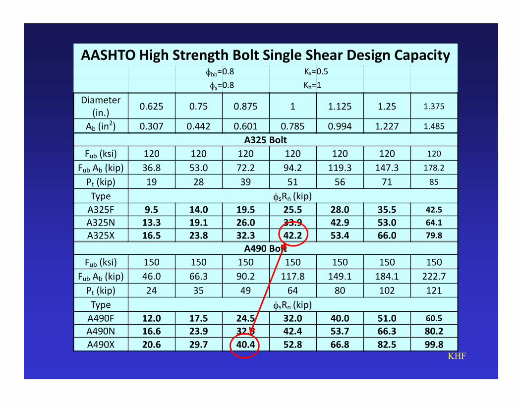
AASHTO High Strength Bolt Single Shear Design Capacityfbb=0.8 Ks=0.5
fs=0.8 Kh=1
Diameter (in.)
0.625 0.75 0.875 1 1.125 1.25 1.375
Ab (in2) 0.307 0.442 0.601 0.785 0.994 1.227 1.485
A325 Bolt
Fub (ksi) 120 120 120 120 120 120 120
Fub Ab (kip) 36.8 53.0 72.2 94.2 119.3 147.3 178.2
Pt (kip) 19 28 39 51 56 71 85
Type fsRn (kip)
A325F 9.5 14.0 19.5 25.5 28.0 35.5 42.5
A325N 13.3 19.1 26.0 33.9 42.9 53.0 64.1
A325X 16.5 23.8 32.3 42.2 53.4 66.0 79.8
A490 Bolt
Fub (ksi) 150 150 150 150 150 150 150
Fub Ab (kip) 46.0 66.3 90.2 117.8 149.1 184.1 222.7
Pt (kip) 24 35 49 64 80 102 121
Type fsRn (kip)
A490F 12.0 17.5 24.5 32.0 40.0 51.0 60.5
A490N 16.6 23.9 32.5 42.4 53.7 66.3 80.2
A490X 20.6 29.7 40.4 52.8 66.8 82.5 99.8KHF

Slip Critical Connections
Class Typical Surface
Slip Coefficient
Old Specification
New Specification
A Mill Scale 0.33 0.30
BZinc Rich Paint
and Blasted0.50 0.50
C Galvanized 0.33 0.30*
DOrganic Zinc
Rich- 0.45
KHF
*Do not wire brush the surfaceRequired tension for A325 > 1 in. diameter increased
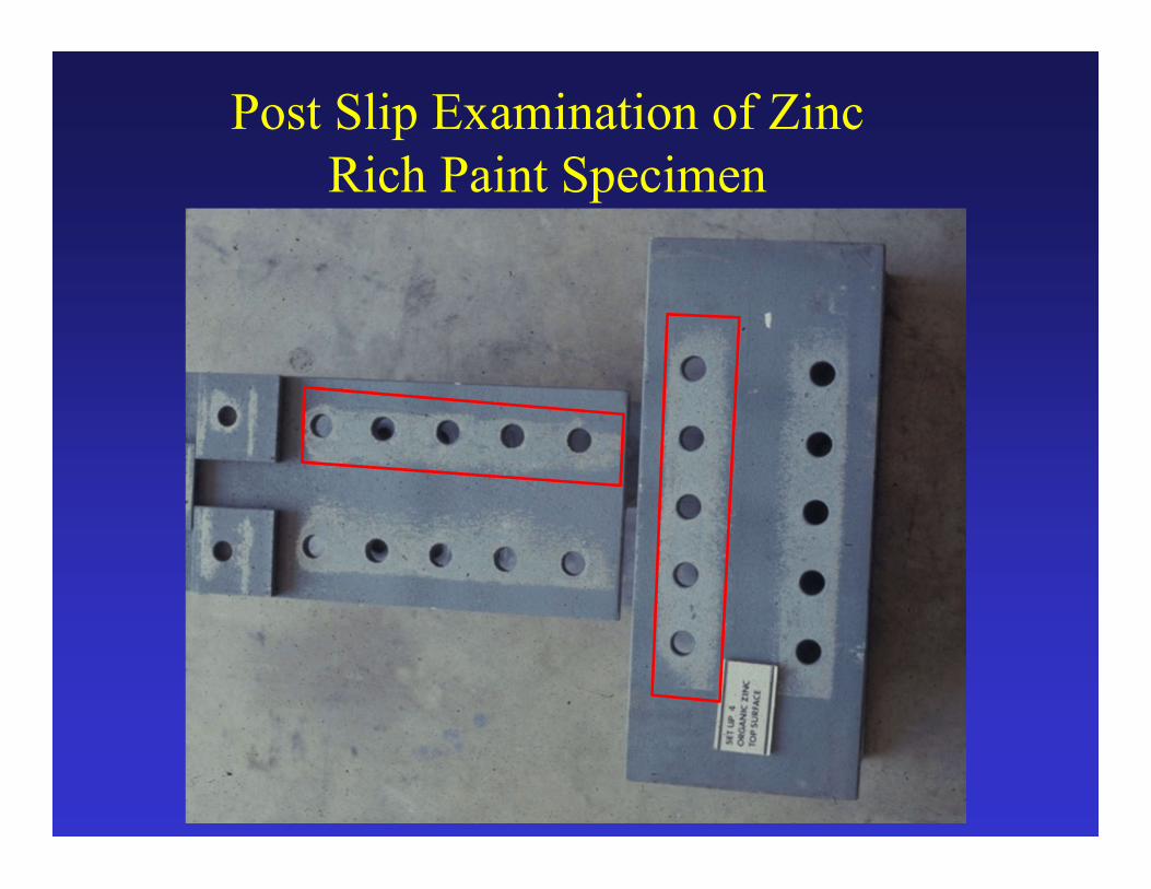
Post Slip Examination of Zinc Rich Paint Specimen

RCSC Fig. C-3.1Areas for Unqualified Paints
1. Area Outside of Shaded Area may have Unqualified Paints.
2. Edges of Plates Not Participating in Developing Slip Resistance.
3. Therefore Do Not Have to Be in Contact.

Footnote on Bolting
• New Hole Size
– 1 inch and greater: Standard hole = diameter of fastener +1/8 in.
• Miss drilled holes- fill with fully tensioned high strength bolt (Category B fatigue strength)
• New electric wrenches can be programmed for required turn of the nut

New Connection Design Criteria and Methods
Remove applicability of the 75 percent and average rules in Article 6.13.1 to the design of bolted and welded splices for flexural members.
75 percent rules are applicable to connections and splices for primary members subject to axial tension or compression only.
Clarify application of rules to primary members subjected to force effects acting in multiple directions due to combined loading.

Bolted Field Splices of Flexural Members
Revised general article on design of bolted splices for flexural members implementing new simplified bolted splice design procedure
Removal of check for slip of bolts during erection of steel
• The purpose is implementation of simplified design procedure and more economical field splice designs.

Expensive and Slow to Erect Field Splice
Field Splice92 bolts in each web32 bolts each flangeTotal 312 bolts936 holes
Bolts: 312x$20= $6,240Labor: 312x10 min= 52 field hours each splice
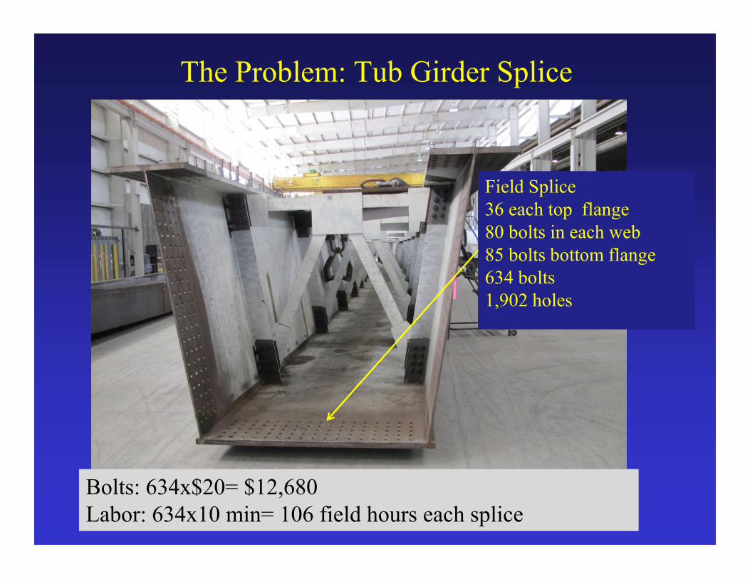
The Problem: Tub Girder Splice
Field Splice36 each top flange80 bolts in each web85 bolts bottom flange634 bolts1,902 holes
Bolts: 634x$20= $12,680Labor: 634x10 min= 106 field hours each splice
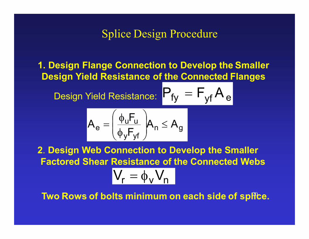
Splice Design Procedure
1. Design Flange Connection to Develop the Smaller Design Yield Resistance of the Connected Flanges
Design Yield Resistance:
2. Design Web Connection to Develop the Smaller Factored Shear Resistance of the Connected Webs
Two Rows of bolts minimum on each side of splice.20
gnyfy
uue AA
F
FA
f
f
nvr VV f
eyffy AFP

Positive Flange Moment Capacity CheckBottom Flange in Tension
Moment Capacity:Pfy for the Bottom Flange x Moment Arm to Mid- Depth
of Deck= (Fyf x Ae ) x A 21
2
tt
2
tDA s
haunchft
eyffy AFP
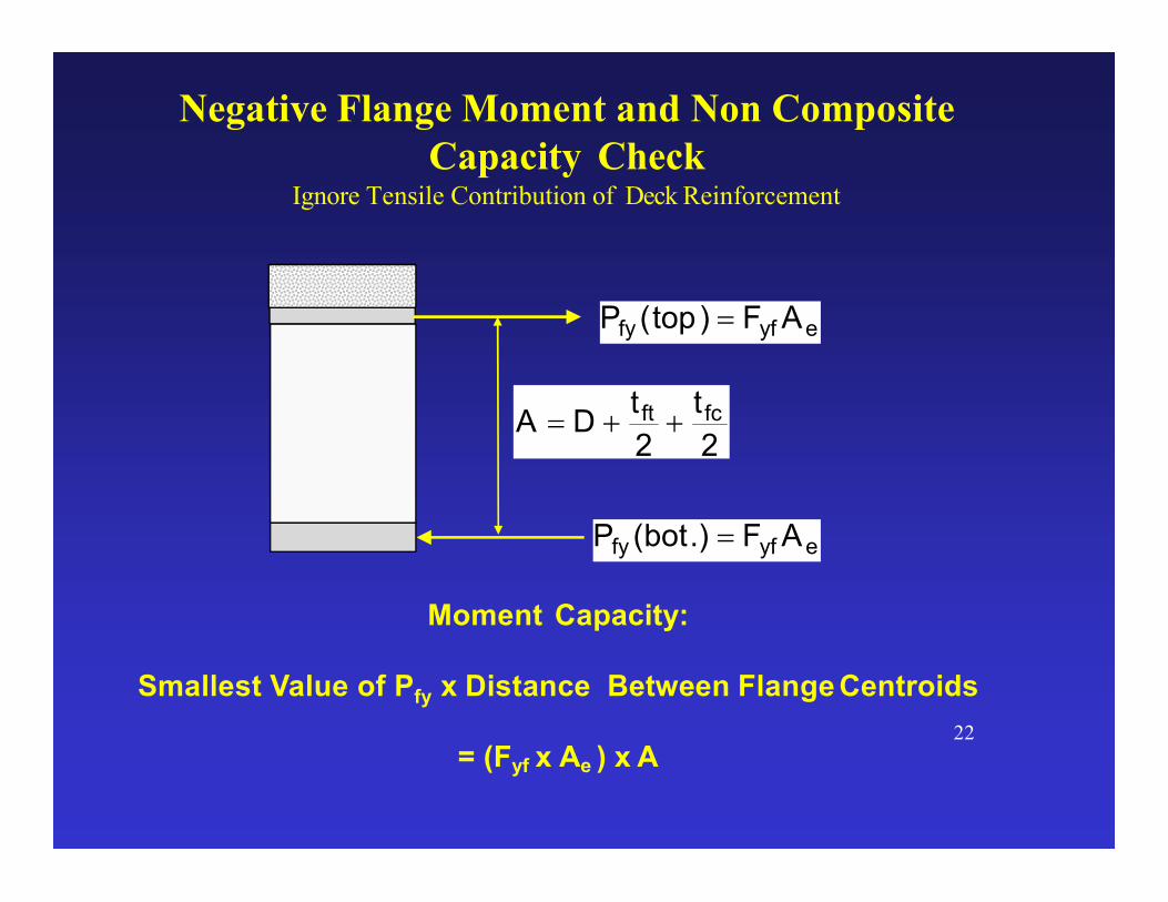
Negative Flange Moment and Non Composite Capacity Check
Ignore Tensile Contribution of Deck Reinforcement
Moment Capacity:
Smallest Value of Pfy x Distance Between Flange Centroids
= (Fyf x Ae ) x A22
2
t
2
tDA fcft
eyffy AF)top(P
eyffy AF.)bot(P
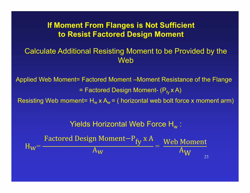
Calculate Additional Resisting Moment to be Provided by the Web
Applied Web Moment= Factored Moment –Moment Resistance of the Flange
= Factored Design Moment- (Pfy x A)
Resisting Web moment= Hw x Aw = ( horizontal web bolt force x moment arm)
Yields Horizontal Web Force Hw :
23
If Moment From Flanges is Not Sufficient to Resist Factored Design Moment
Hw= Factored Design Moment−Pfy x A
Aw=
Web MomentAW
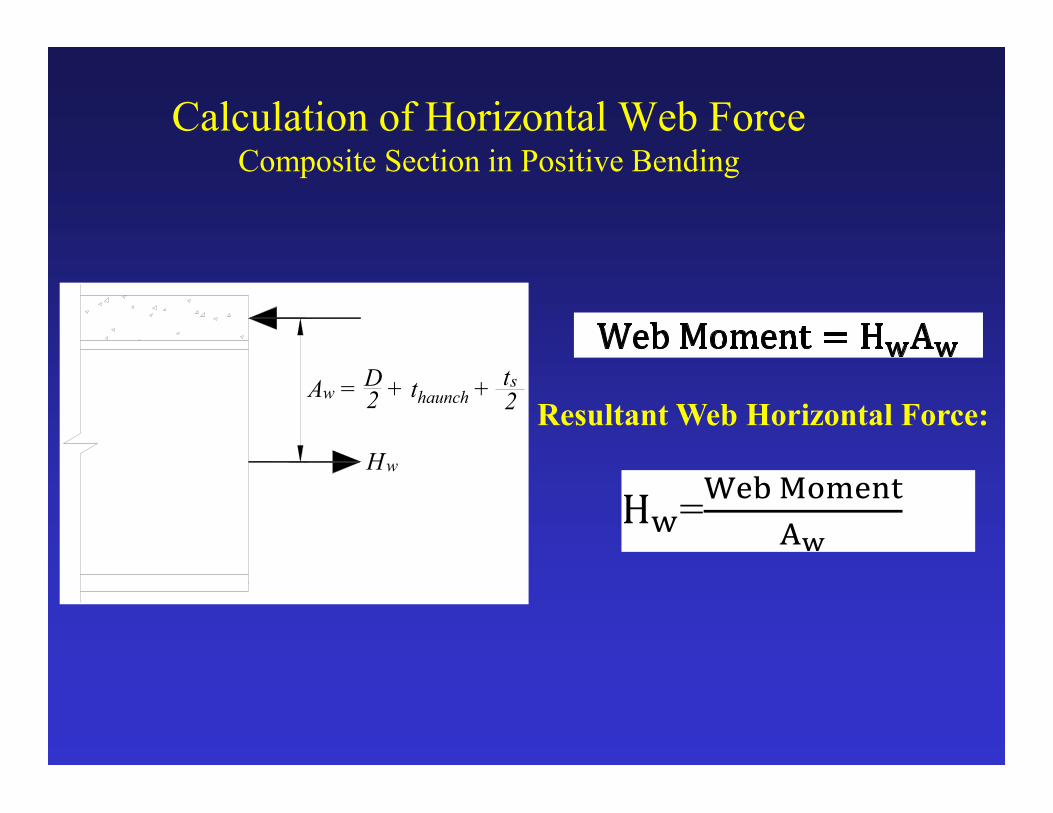
Calculation of Horizontal Web Force Composite Section in Positive Bending
Aw = D2 + thaunch +
Hw
ts
2Resultant Web Horizontal Force:
H�=��� ������
��

Calculation of Horizontal Web Force Composite Section in Negative Bending or
Non-Composite Section
D2
D2
D2
Hw
2
Hw
2
22
DHMomentWeb
w
4/D
MomentWebH w
Resultant Web Horizontal Force:

Hw = Horizontal Force in Web To Resist Design MomentVr= Vertical Force in Web = Factored Shear Resistance of the Web
26
2w2
nv2
w2
r HVHVR f
Web Splice Force=Vector Resultant from Moment and Shear
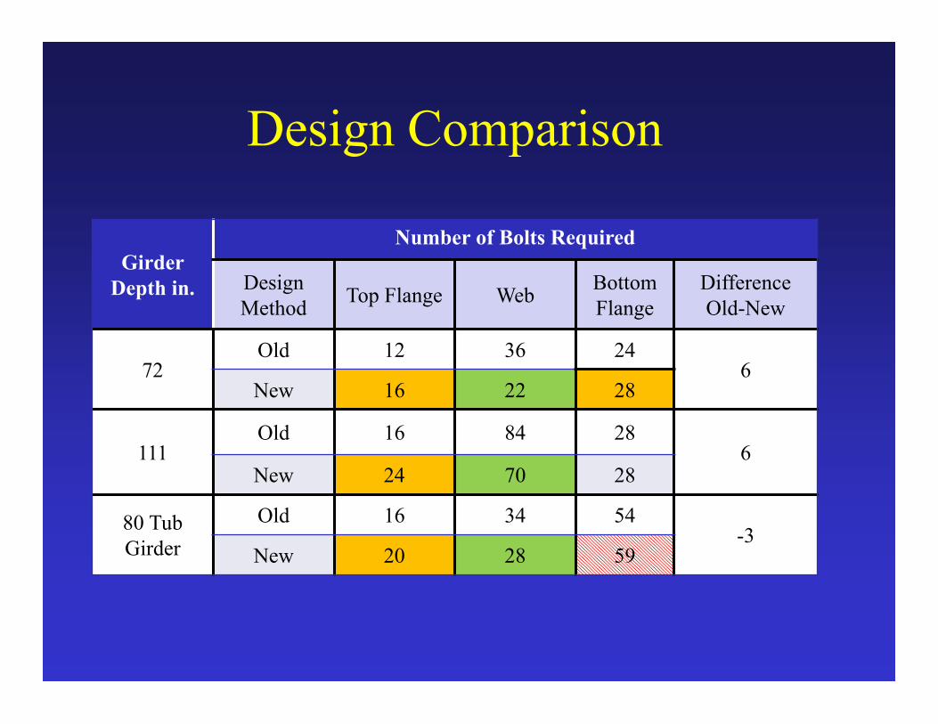
Design Comparison
Girder Depth in.
Number of Bolts Required
Design Method
Top Flange WebBottom Flange
Difference Old-New
72Old 12 36 24
6New 16 22 28
111Old 16 84 28
6New 24 70 28
80 Tub Girder
Old 16 34 54-3
New 20 28 59

Validation Finite Element Analysis
10
9
9
16 T H K .
5
8 T H K.
5
8 T H K.
916 T H K .
7
16 T H K .
10
2
33
Sp
a.
@3
inc
h
204 Web Bolts
10
9
9
16 T H K .
5
8 T H K .
5
8 T H K .
916 T H K .
716 T H K .
10
2
24
Sp
a.
@
4in
ch
100 Web Bolts“Simplified Design of Bolted Splice Connections for Steel Girders” – Frank, Ocel, and Grubb
28

29
o Shell element models in Abaqus
o Adapted fastener models from NCHRP 12-84
o Five loading scenarios– Pure positive moment
– Pure negative moment *
– High shear (as little moment as possible) *
– Proportion design positive moment/shear
– Proportional design negative moment/shear **= deck not present
FEA Model Description
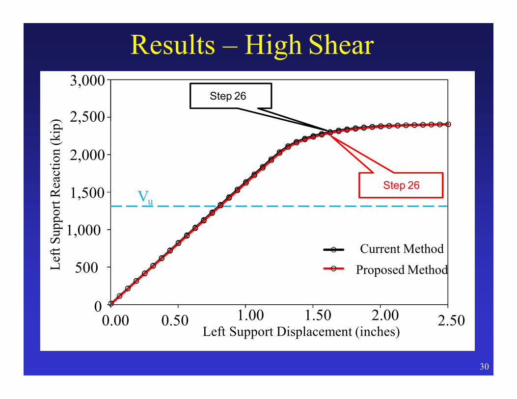
Results – High Shear
0
500
1,000
1,500
0.00 0.50 2.50
Lef
tS
upp
ort
Rea
ctio
n(k
ip)
1.00 1.50 2.00Left Support Displacement (inches)
Current Method
Proposed Method
Vu
3,000
Step 26
30
2,000
2,500
Step 26

CURRENT
“Simplified Design of Bolted Splice Connections for Steel Girders” – Frank, Ocel, and Grubb
31
PROPOSED
Results – High ShearVon Mises Stresses @ Step 26

CURRENT“Simplified Design of Bolted Splice Connections for Steel Girders” – Frank, Ocel, and Grubb
17
PROPOSED
Results – High ShearBolt Shear Forces @ Step 26
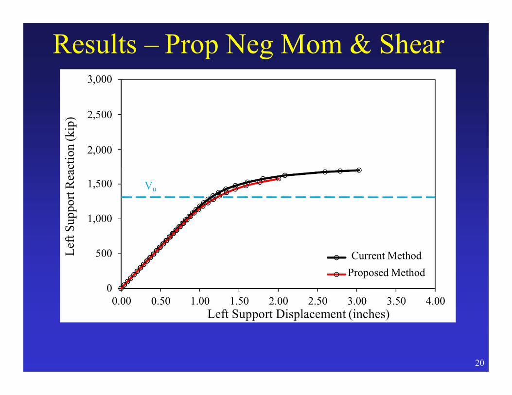
Results – Prop Neg Mom & Shear
0
20
500
1,000
1,500
3,000
2,500
2,000
0.00 0.50 1.00 1.50 2.00 2.50 3.00 3.50 4.00
Lef
tS
up
port
Rea
ctio
n(k
ip)
Left Support Displacement (inches)
Current Method
Proposed Method
Vu

Results – Prop Neg Mom & ShearVon Mises Stresses @ Vu
CURRENT PROPOSED21
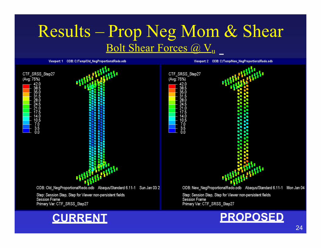
Results – Prop Neg Mom & ShearBolt Shear Forces @ Vu
CURRENT PROPOSED24

– Application of the new proposed design provisions for bolted field splices will typically result in a few more bolts in the flange splices and significantly fewer bolts in the web splices than under the current design provisions.
– The overall simplification in the design procedure should result in easier interpretation of the provisions, faster and more efficient design of field splices, and more consistent and cost-effective designs.
– Clarifications to the application of the 75 percent and average rules to the design of connections and splices in primary members at the strength limit state subject to combined force effects should also be beneficial to designers.
Anticipated Effect on Bridges:

Bolted Field Splices Document
37
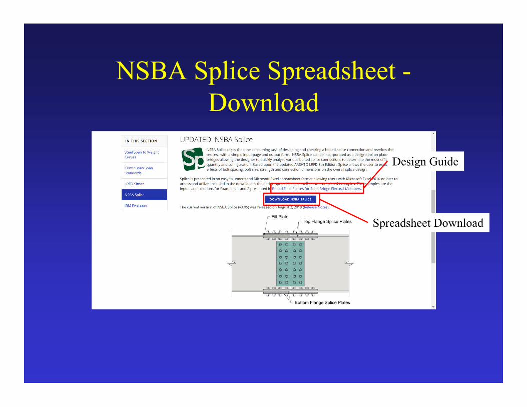
www.steelbridges.org/nsbasplice

Design Tools – Splice Spreadsheet

NSBA Splice Spreadsheet
• NSBA Splice Spreadsheet
– Plate Girder Bolted Splice Design Tool.
– 8th Edition AASHTO Design Specification Compliant.
– Updated May 2019.
– Subscribe to NSBA Newsletter for up-to-date information.
www.steelbridges.org/nsbasplice

NSBA Splice Spreadsheet -Download

NSBA Splice Spreadsheet -Download
NSBA Splice Spreadsheet -Download
Design Guide
Spreadsheet Download
Result of Changes to Field Splice Design
• Reduced Design Effort and Cost, Lower Connection Costs, & Faster Erection
KHF

A New Day- Another Bridge
44


