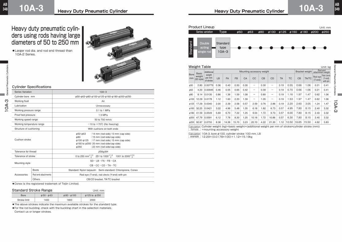
Heavy Duty Pneumatic Cylinder 10A-3 10A-3 General Pneumatic Cylinders 348 AB Heavy Duty Pneumatic Cylinder 10A-3 General Pneumatic Cylinders 10A-3 349 AB Cylinder Specifications Working fluid Lubrication Working pressure range Proof test pressure Working speed range Working temperature range Structure of cushioning Cushion stroke Tolerance for thread Tolerance of stroke Mounting style Boots Rod end attachments Others Accessories φ50 ・φ63 ・φ80 ・φ100 ・φ125 ・φ160 ・φ180 ・φ200 ・φ250 Air Unnecessary 0.1 to 1 MPa 1.5 MPa 50 to 700 mm/s -10 to +70℃ (No freezing) With cushions on both ends Standard Stroke Range Unit: mm Stroke limit 1400 1800 2000 JIS6g/6H 0 to 250 mm 251 to 1000 1001 to 2000 SD・LB・FA・FB・CA CB・CC・CD・TA・TC Standard: Nylon tarpaulin Semi-standard: Chloroprene, Conex Rod eye (T-end), rod clevis (Y-end) with pin CB/CD bracket, TA/TC bracket +1.0 0 +1.5 0 +2.0 0 φ50 ・φ63 :14 mm (rod side) 13 mm (cap side) φ80 :15 mm (rod side/cap side) φ100 ・φ125 :17 mm (rod side) 15 mm (cap side) φ160 to φ200 :20 mm (rod side/cap side) φ250 :22 mm (rod side/cap side) ●Conex is the registered trademark of Teijin Limited. ●The above strokes indicate the maximum available strokes for the standard type. ●For the rod buckling, check with the buckling chart in the selection materials. Contact us or longer strokes. Series Variation Cylinder bore mm 10A-3 Bore φ50 ・φ63 φ80 ・φ100 φ125 to φ250 ●Larger rod dia. and rod end thread than 10A-2 Series. Heavy duty pneumatic cylin- ders using rods having large diameters of 50 to 250 mm Weight Table Bore mm Basic weight (SD style) Mounting accessory weight LB FB CB CC Rod eye (T-end) Rod clevis (Y-end) with pin Rod end attachment weight Bracket weight φ50 φ63 φ80 φ100 φ125 φ160 φ180 φ200 φ250 0.36 0.46 0.86 1.12 2.00 3.22 5.69 6.12 8.38 FA 0.40 0.55 1.36 1.60 2.39 4.96 6.70 7.78 14.36 0.50 0.65 1.59 2.20 2.58 5.48 7.22 8.30 15.70 CA 0.26 0.42 1.08 1.39 0.57 1.35 1.25 1.25 3.23 0.30 0.39 0.80 1.05 0.76 1.82 1.72 1.72 4.22 CD TA/TC 1.06 1.06 1.47 1.47 3.05 8.15 8.15 8.15 15.50 0.66 0.66 1.97 1.97 2.60 7.80 7.80 7.80 16.65 TA 0.19 0.19 0.19 0.19 0.19 0.57 0.57 0.57 1.12 TC CB 0.55 0.70 1.16 1.53 2.20 4.95 6.00 6.30 10.50 - - - - 2.59 6.18 9.04 10.18 20.10 - - - - 2.86 6.73 9.73 10.86 21.30 2.80 4.20 8.14 12.29 17.29 32.25 41.59 47.79 92.87 Additional weight per mm of stroke 0.00779 0.00945 0.0135 0.0178 0.0340 0.0421 0.0549 0.0591 0.0755 0.21 0.21 0.62 0.62 1.24 2.40 2.40 2.40 4.62 0.41 0.41 1.06 1.06 1.47 3.32 3.32 3.32 5.83 Product Lineup Series variation Type Standard Standard type 10A-3 φ50 φ63 φ80 φ100 φ125 φ160 φ180 φ200 φ250 Double acting single rod Unit: mm Unit: kg Calculation formula Cylinder weight (kg)=basic weight+(additional weight per mm of stroke×cylinder stroke (mm)) +mounting accessory weight Calculation example 10A-3, bore φ100, cylinder stroke 100 mm, LB 12.29+(0.0178×100)+1.12=15.19kg
Transcript
Heavy Duty Pneumatic Cylinder10A-310A-3 General Pneumatic Cylinders
φ50・φ63 : 14 mm (rod side) 13 mm (cap side)φ80 : 15 mm (rod side/cap side)φ100・φ125 : 17 mm (rod side) 15 mm (cap side)φ160 to φ200 : 20 mm (rod side/cap side)φ250 : 22 mm (rod side/cap side)
●Conex is the registered trademark of Teijin Limited.
●The above strokes indicate the maximum available strokes for the standard type.●For the rod buckling, check with the buckling chart in the selection materials.Contact us or longer strokes.
Series Variation
Cylinder bore mm
10A-3
Bore φ50・φ63 φ80・φ100 φ125 to φ250
●Larger rod dia. and rod end thread than 10A-2 Series.
Heavy duty pneumatic cylin-ders using rods having large diameters of 50 to 250 mm
Weight Table
Bore
mm
Basicweight
(SD style)
Mounting accessory weight
LB FB CBCCRod eye(T-end)
Rod clevis(Y-end)with pin
Rod endattachment weightBracket weight
φ50
φ63
φ80
φ100
φ125
φ160
φ180
φ200
φ250
0.36
0.46
0.86
1.12
2.00
3.22
5.69
6.12
8.38
FA
0.40
0.55
1.36
1.60
2.39
4.96
6.70
7.78
14.36
0.50
0.65
1.59
2.20
2.58
5.48
7.22
8.30
15.70
CA
0.26
0.42
1.08
1.39
0.57
1.35
1.25
1.25
3.23
0.30
0.39
0.80
1.05
0.76
1.82
1.72
1.72
4.22
CD TA/TC
1.06
1.06
1.47
1.47
3.05
8.15
8.15
8.15
15.50
0.66
0.66
1.97
1.97
2.60
7.80
7.80
7.80
16.65
TA
0.19
0.19
0.19
0.19
0.19
0.57
0.57
0.57
1.12
TC CB
0.55
0.70
1.16
1.53
2.20
4.95
6.00
6.30
10.50
-
-
-
-
2.59
6.18
9.04
10.18
20.10
-
-
-
-
2.86
6.73
9.73
10.86
21.30
2.80
4.20
8.14
12.29
17.29
32.25
41.59
47.79
92.87
Additionalweightper mmof stroke
0.00779
0.00945
0.0135
0.0178
0.0340
0.0421
0.0549
0.0591
0.0755
0.21
0.21
0.62
0.62
1.24
2.40
2.40
2.40
4.62
0.41
0.41
1.06
1.06
1.47
3.32
3.32
3.32
5.83
Product LineupSeries variation Type
Standard Standard
type10A-3
φ50 φ63 φ80 φ100 φ125 φ160 φ180 φ200 φ250
Doubleactingsingle rod
Unit: mm
Unit: kg
Calculationformula
Cylinder weight (kg)=basic weight+(additional weight per mm of stroke×cylinder stroke (mm))+mounting accessory weight
Calculationexample
10A-3, bore φ100, cylinder stroke 100 mm, LB12.29+(0.0178×100)+1.12=15.19kg
Heavy Duty Pneumatic Cylinder10A-310A-3 General Pneumatic Cylinders
350AB
Heavy Duty Pneumatic Cylinder 10A-3General P
neumatic C
ylinders 10A-3
351AB
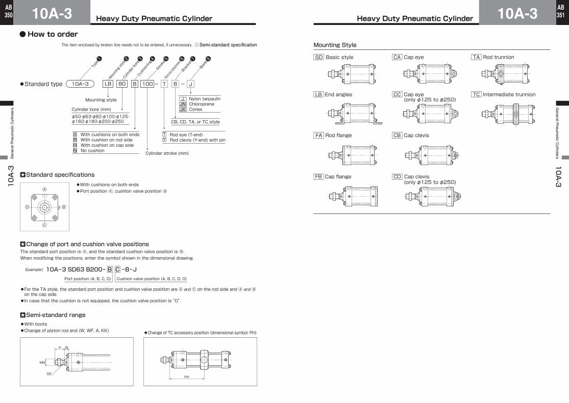
Type❶
Stroke❺
Rod end attachment❻
Bracket❼
Boots❽
Cylinder bore❸
Mounting style❷
-T J●Standard type 10A-3 B
Nylon tarpaulinChloropreneConex
CB, CD, TA, or TC style
Cylinder bore (mm)
Cylinder stroke (mm)
Cushioning❹
-
B With cushions on both endsR With cushion on rod sideH With cushion on cap sideN No cushion
T Rod eye (T-end)Y Rod clevis (Y-end) with pin
LB 80 B 100
Mounting style
φ50・φ63・φ80・φ100・φ125・φ160・φ180・φ200・φ250
JJNJK
Port position (A, B, C, D) Cushion valve position (A, B, C, D, 0)
●With boots●Change of piston rod end (W, WF, A, KK) ●Change of TC accessory position (dimensional symbol: PH)
Standard specifications
Ⓓ
Ⓒ
Ⓑ
Ⓐ●With cushions on both ends●Port position Ⓐ, cushion valve position Ⓑ
10A-3 SD63 B200- B C -B-JExample)
Change of port and cushion valve positionsThe standard port position is Ⓐ, and the standard cushion valve position is Ⓑ.When modifying the positions, enter the symbol shown in the dimensional drawing.
●For the TA style, the standard port position and cushion valve position are Ⓐ and Ⓒ on the rod side and Ⓐ and Ⓑ on the cap side.●In case that the cushion is not equipped, the cushion valve position is “0”.
Semi-standard range
A W
KK
MM
PH
Semi-standard specificationThe item enclosed by broken line needs not to be entered, if unnecessary.
SD Basic style
FB Cap flange
FA Rod flange
TC Intermediate trunnion
CB Cap clevis
CC Cap eye
(only φ125 to φ250)
CA Cap eye
LB End angles
Mounting Style
CD
(only φ125 to φ250)
Cap clevis
TA Rod trunnion
●How to order
Heavy Duty Pneumatic Cylinder10A-310A-3 General Pneumatic Cylinders
352AB
Heavy Duty Pneumatic Cylinder 10A-3General P
neumatic C
ylinders 10A-3
353AB
KK
LF+stroke BBJF
BB
ZB+stroke
A
ZJ+stroke
2-EE
5
B D
Max. 10E
RR
P+stroke
H+stroke
h
K
FPW
MM
Cushion valves
2×4ーDD
Ⓓ
Ⓒ
Ⓑ
Ⓐ
Width across flats of lock nut for rod end attachment: B1
B D
MM
KK
Width across flats of lock nut for rod end attachment: B1
2ーEE2×4ーDD
LL+stroke BB
J
BB
H+stroke K
Cushion valves
ZB+stroke
A
ZJ+stroke
P+stroke
h
YPWF
VF
VFF
Max. 14E
RE
RR
Ⓓ
Ⓒ
Ⓑ
Ⓐ
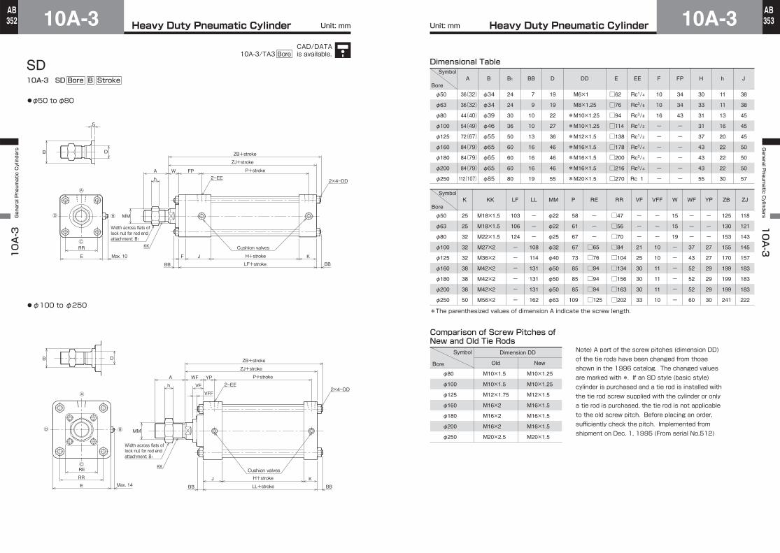
10A-3 SD Bore B Stroke
●φ50 to φ80
●φ100 to φ250
SD Dimensional Table
φ50
φ63
φ80
φ100
φ125
φ160
φ180
φ200
φ250
φ50
φ63
φ80
φ100
φ125
φ160
φ180
φ200
φ250
Symbol
Bore
36(32)
36(32)
44(40)
54(49)
72(67)
84(79)
84(79)
84(79)
112(107)
A
φ34
φ34
φ39
φ46
φ55
φ65
φ65
φ65
φ85
B
24
24
30
36
50
60
60
60
80
B1
7
9
10
10
13
16
16
16
19
BB DD
19
19
22
27
36
46
46
46
55
D
□62
□76
□94
□114
□138
□178
□200
□216
□270
E
Rc1/4
Rc3/8
Rc3/8
Rc1/2
Rc1/2
Rc3/4
Rc3/4
Rc3/4
Rc 1
EE
10
10
16
-
-
-
-
-
-
F
34
34
43
-
-
-
-
-
-
FP
30
33
31
31
37
43
43
43
55
H
11
11
13
16
20
22
22
22
30
h
38
38
45
45
45
50
50
50
57
J
M6×1
M8×1.25
*M10×1.25
*M10×1.25
*M12×1.5
*M16×1.5
*M16×1.5
*M16×1.5
*M20×1.5
25
25
32
32
32
38
38
38
50
K
M18×1.5
M18×1.5
M22×1.5
M27×2
M36×2
M42×2
M42×2
M42×2
M56×2
KK
103
106
124
-
-
-
-
-
-
LF
-
-
-
108
114
131
131
131
162
LL
φ22
φ22
φ25
φ32
φ40
φ50
φ50
φ50
φ63
MM
58
61
67
67
73
85
85
85
109
P
□47
□56
□70
□84
□104
□134
□156
□163
□202
RR
-
-
-
21
25
30
30
30
33
VF
-
-
-
37
43
52
52
52
60
WF
15
15
19
-
-
-
-
-
-
W
-
-
-
27
27
29
29
29
30
YP
125
130
153
155
170
199
199
199
241
ZB
118
121
143
145
157
183
183
183
222
ZJ
-
-
-
10
10
11
11
11
10
VFF
-
-
-
RE
□65
□76
□94
□94
□94
□125
*The parenthesized values of dimension A indicate the screw length.
Comparison of Screw Pitches of New and Old Tie Rods
φ80
φ100
φ125
φ160
φ180
φ200
φ250
Symbol
Bore
M10×1.5
M10×1.5
M12×1.75
M16×2
M16×2
M16×2
M20×2.5
Old
M10×1.25
M10×1.25
M12×1.5
M16×1.5
M16×1.5
M16×1.5
M20×1.5
New
Dimension DD Note) A part of the screw pitches (dimension DD) of the tie rods have been changed from those shown in the 1996 catalog. The changed values are marked with *. If an SD style (basic style) cylinder is purchased and a tie rod is installed with the tie rod screw supplied with the cylinder or only a tie rod is purchased, the tie rod is not applicable to the old screw pitch. Before placing an order, sufficiently check the pitch. Implemented from shipment on Dec. 1, 1995 (From serial No.512)
Symbol
Bore
Unit: mm Unit: mm
CAD/DATAis available.10A-3/TA3 Bore
Heavy Duty Pneumatic Cylinder10A-310A-3 General Pneumatic Cylinders
354AB
Heavy Duty Pneumatic Cylinder 10A-3General P
neumatic C
ylinders 10A-3
355AB
KK
SA+stroke
ALAO
JFAL
AO
XA+stroke
A2-EE
5
B D
Max. 10
UA
R
P+stroke
H+stroke
h
K
FPW
MMⒹ
Ⓒ
Ⓑ
Ⓐ
ATAH
AE
E
2×2ーAB Cushion valves
Width across flats of lock nut for rod end attachment: B1
B D
MM
KK
2-EE
SA+strokeAO AO
J KAL ALH+stroke
XA+stroke
A P+stroke
h
YPWFVF
UA
R
Ⓓ
Ⓒ
Ⓑ
Ⓐ
RE
E Max. 14
2×2ーAB
AT
AH
AE
Cushion valves
Width across flats of lock nut for rod end attachment: B1
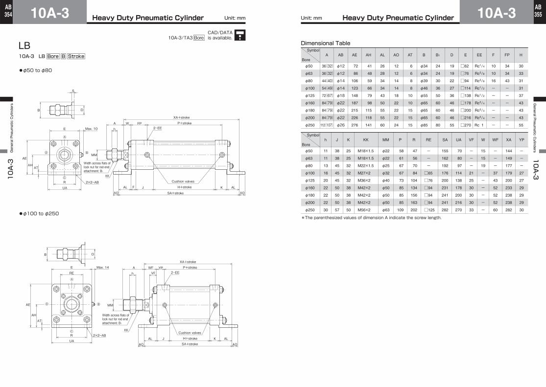
●φ50 to φ80
●φ100 to φ250
LB10A-3 LB Bore B Stroke
Dimensional Table
φ50
φ63
φ80
φ100
φ125
φ160
φ180
φ200
φ250
φ50
φ63
φ80
φ100
φ125
φ160
φ180
φ200
φ250
φ12
φ12
φ14
φ14
φ18
φ22
φ22
φ22
φ26
AB
72
86
106
123
148
187
215
226
276
AE
41
48
59
66
79
98
115
118
141
AH
26
28
34
34
43
50
55
55
60
AL
φ34
φ34
φ39
φ46
φ55
φ65
φ65
φ65
φ85
B
12
12
14
14
18
22
22
22
24
AO
6
6
8
8
10
10
15
15
15
AT
□62
□76
□94
□114
□138
□178
□200
□216
□270
E
Rc1/4
Rc3/8
Rc3/8
Rc1/2
Rc1/2
Rc3/4
Rc3/4
Rc3/4
Rc 1
EE
10
10
16
-
-
-
-
-
-
F
34
34
43
-
-
-
-
-
-
FP
30
33
31
31
37
43
43
43
55
H
11
11
13
16
20
22
22
22
30
h
38
38
45
45
45
50
50
50
57
J
19
19
22
27
36
46
46
46
55
D
25
25
32
32
32
38
38
38
50
K
M18×1.5
M18×1.5
M22×1.5
M27×2
M36×2
M42×2
M42×2
M42×2
M56×2
KK
φ22
φ22
φ25
φ32
φ40
φ50
φ50
φ50
φ63
MM
58
61
67
67
73
85
85
85
109
P
47
56
70
84
104
134
156
163
202
R
155
162
192
176
200
231
241
241
282
SA
70
80
97
114
138
178
200
216
270
UA
144
149
177
179
200
233
238
238
282
XA
-
-
-
21
25
30
30
30
33
VF
-
-
-
37
43
52
52
52
60
WF
15
15
19
-
-
-
-
-
-
W
-
-
-
27
27
29
29
29
30
YP
24
24
30
36
50
60
60
60
80
B1
-
-
-
RE
□65
□76
□94
□94
□94
□125
36(32)
36(32)
44(40)
54(49)
72(67)
84(79)
84(79)
84(79)
112(107)
A
*The parenthesized values of dimension A indicate the screw length.
Symbol
Bore
Symbol
Bore
Unit: mm Unit: mm
CAD/DATAis available.10A-3/TA3 Bore
Heavy Duty Pneumatic Cylinder10A-310A-3 General Pneumatic Cylinders
356AB
Heavy Duty Pneumatic Cylinder 10A-3General P
neumatic C
ylinders 10A-3
357AB
KK
4ーFB 2ーEE
VD J H+stroke K
ZB+stroke
AMax. 10E
TFUF
REF
P+stroke
LF+stroke
h
BBW
F
YPWF
D
MM
B
Ⓐ
Ⓒ Cushion valves
Width across flats of lock nut for rod end attachment: B1
Ⓓ Ⓑ
RE
EF R
UF
TF
Max. 14E
4ーFB2ーEE
ZB+stroke
A P+stroke
h
YPWF
KKVD J H+stroke K
LF+stroke BBW
F
MM
B
Ⓐ
Ⓒ
D
Cushion valves
Width across flats of lock nut for rod end attachment: B1
ⒷⒹ
●φ50 to φ80
●φ100 to φ250
FA10A-3 FA Bore B Stroke
Dimensional Table
φ50
φ63
φ80
φ100
φ125
φ160
φ180
φ200
φ250
φ50
φ63
φ80
φ100
φ125
φ160
φ180
φ200
φ250
7
9
10
10
13
16
16
16
19
BB
φ34
φ34
φ39
φ46
φ55
φ65
φ65
φ65
φ85
B
□62
□76
□94
□114
□138
□178
□200
□216
□270
E
Rc1/4
Rc3/8
Rc3/8
Rc1/2
Rc1/2
Rc3/4
Rc3/4
Rc3/4
Rc 1
EE
10
10
16
16
16
20
20
20
25
F
30
33
31
31
37
43
43
43
55
H
11
11
13
16
20
22
22
22
30
h
38
38
45
45
45
50
50
50
57
J
φ9
φ9
φ12
φ12
φ14
φ18
φ18
φ18
φ22
FB
19
19
22
27
36
46
46
46
55
D
25
25
32
32
32
38
38
38
50
K
M18×1.5
M18×1.5
M22×1.5
M27×2
M36×2
M42×2
M42×2
M42×2
M56×2
KK
φ22
φ22
φ25
φ32
φ40
φ50
φ50
φ50
φ63
MM
103
106
124
124
130
151
151
151
187
LF
58
61
67
67
73
85
85
85
109
P
47
56
70
84
104
134
156
163
201
R
86
98
119
138
168
212
234
250
312
TF
104
116
143
162
196
248
270
286
356
UF
5
5
5
5
9
10
10
10
8
VD
125
130
153
155
170
199
199
199
241
ZB
15
15
19
21
27
32
32
32
35
W
24
24
27
27
27
29
29
29
30
YP
25
25
35
37
43
52
52
52
60
WF
65
76
95
115
138
178
200
216
270
EF
24
24
30
36
50
60
60
60
80
B1
-
-
-
RE
□65
□76
□94
□94
□94
□125
36(32)
36(32)
44(40)
54(49)
72(67)
84(79)
84(79)
84(79)
112(107)
A
*The parenthesized values of dimension A indicate the screw length.
Symbol
Bore
Symbol
Bore
Unit: mm Unit: mm
CAD/DATAis available.10A-3/TA3 Bore
Heavy Duty Pneumatic Cylinder10A-310A-3 General Pneumatic Cylinders
358AB
Heavy Duty Pneumatic Cylinder 10A-3General P
neumatic C
ylinders 10A-3
359AB
DB
5
2ーEE
ZF+stroke
A P+stroke
h
FPW
KK
MM
Max. 10 E 4ーFB
EFR
UF
TF
F
KF JLF+stroke
H+stroke
Ⓐ
ⒸCushion valves
Width across flats of lock nut for rod end attachment: B1
ⒹⒷ
DB
Max. 14 4ーFB
EFR
UF
TF
2ーEE
ZF+stroke
A P+stroke
h VF
KK
MMRE
F
KLL+stroke
H+strokeJ
WF YP
E
Ⓓ
Ⓐ
Ⓒ
Ⓑ
Cushion valves
Width across flats of lock nut for rod end attachment: B1
●φ50 to φ80
●φ100 to φ250
FB10A-3 FB Bore B Stroke
Dimensional Table
φ50
φ63
φ80
φ100
φ125
φ160
φ180
φ200
φ250
φ50
φ63
φ80
φ100
φ125
φ160
φ180
φ200
φ250
φ34
φ34
φ39
φ46
φ55
φ65
φ65
φ65
φ85
B
□62
□76
□94
□114
□138
□178
□200
□216
□270
E
Rc1/4
Rc3/8
Rc3/8
Rc1/2
Rc1/2
Rc3/4
Rc3/4
Rc3/4
Rc 1
EE
10
10
16
16
16
20
20
20
25
F
30
33
31
31
37
43
43
43
55
H
11
11
13
16
20
22
22
22
30
h
38
38
45
45
45
50
50
50
57
J
34
34
43
-
-
-
-
-
-
FP
φ9
φ9
φ12
φ12
φ14
φ18
φ18
φ18
φ22
FB
19
19
22
27
36
46
46
46
55
D
M18×1.5
M18×1.5
M22×1.5
M27×2
M36×2
M42×2
M42×2
M42×2
M56×2
25
25
32
32
32
38
38
38
50
K KK
104
116
143
162
196
248
270
286
356
φ22
φ22
φ25
φ32
φ40
φ50
φ50
φ50
φ63
MM
103
106
124
-
-
-
-
-
-
LF
-
-
-
108
114
131
131
131
162
LL
58
61
67
67
73
85
85
85
109
P
47
56
70
84
104
134
156
163
201
R
86
98
119
138
168
212
234
250
312
TF
-
-
-
RE UF
-
-
-
21
25
30
30
30
33
VF
128
131
159
161
173
203
203
203
247
ZF
15
15
19
-
-
-
-
-
-
W
-
-
-
27
27
29
29
29
30
YP
-
-
-
37
43
52
52
52
60
WF
65
76
95
115
138
178
200
216
270
EF
24
24
30
36
50
60
60
60
80
B1
□65
□76
□94
□94
□94
□125
36(32)
36(32)
44(40)
54(49)
72(67)
84(79)
84(79)
84(79)
112(107)
A
*The parenthesized values of dimension A indicate the screw length.
Symbol
Bore
Symbol
Bore
Unit: mm Unit: mm
CAD/DATAis available.10A-3/TA3 Bore
Heavy Duty Pneumatic Cylinder10A-310A-3 General Pneumatic Cylinders
360AB
Heavy Duty Pneumatic Cylinder 10A-3General P
neumatic C
ylinders 10A-3
361AB
D
KK
2ーEEAh
FPW P+stroke
ZC+stroke
TKH+strokeJFXC+stroke
EW
Max. 10 E
Ⓓ
Ⓐ
Ⓒ
Ⓑ
5
B
MM
MR
LR
CD
Cushion valvesWidth across flats of lock nut for rod end attachment: B1
Ⓓ
Ⓐ
Ⓒ
Ⓑ
B
Ah VF 2ーEE
LR
CD
MR
WF YP P+stroke
ZC+strokeXC+strokeH+strokeJ
RE MM
TK EW
Max. 14 EKK
D
Cushion valvesWidth across flats of lock nut for rod end attachment: B1
D
Ⓓ
Ⓐ
Ⓒ
Ⓑ
ZC+stroke
LKH+strokeJ
MR
LR
CD
XC+stroke
VFAh
WF P+strokeYP2ーEE
Max. 14 E
EW
B
RE MM
Cushion valves
KK
Width across flats of lock nut for rod end attachment: B1
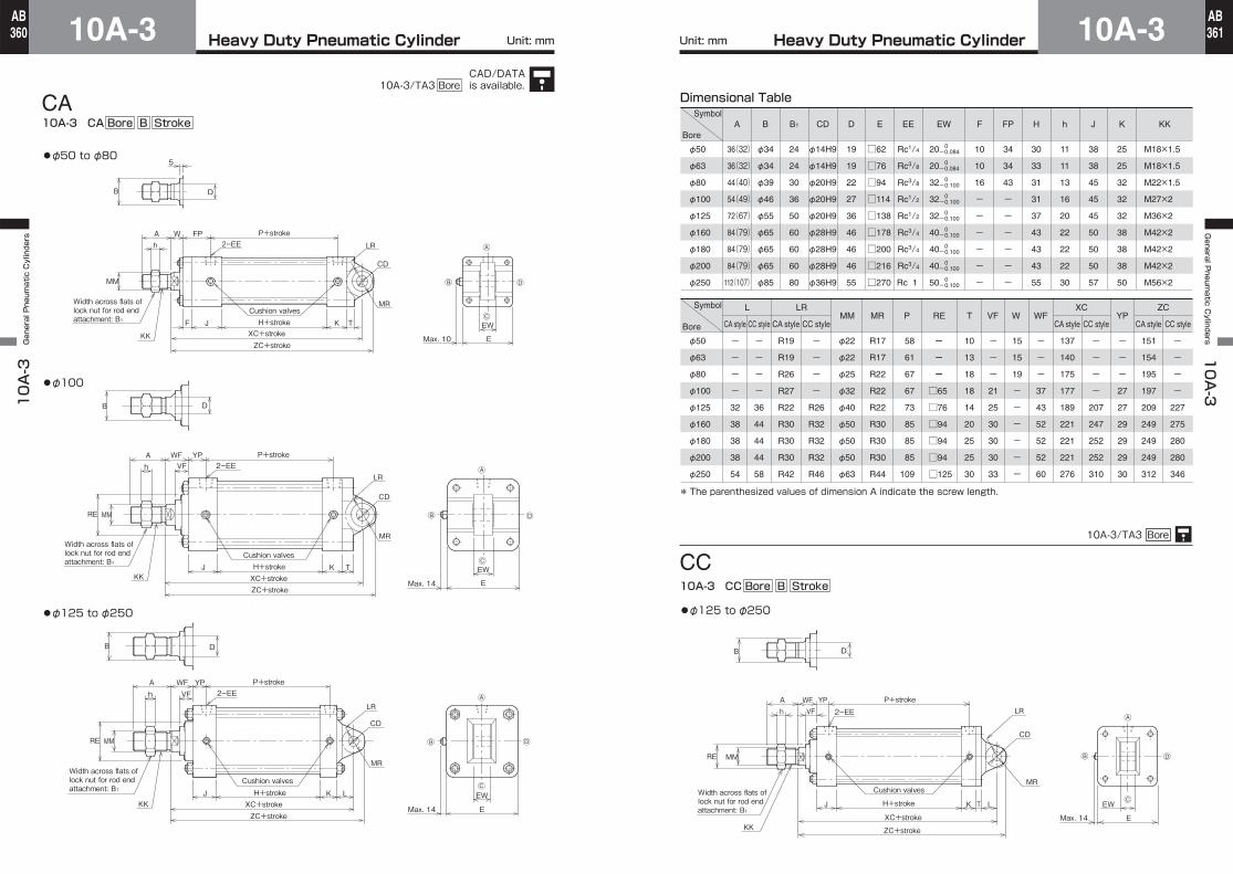
●φ50 to φ80
●φ125 to φ250
CA10A-3 CA Bore B Stroke
●φ100
RE MM
KKMax. 14 E
EW
LR
CD
MR
A WFh VF
YP2ーEE
P+stroke
B
H+stroke
ZC+stroke
XC+stroke
LTKJ
Ⓓ
Ⓐ
Ⓒ
Ⓑ
D
Cushion valvesWidth across flats of lock nut for rod end attachment: B1
B B1 DCD E EE EW F FP H h J K KK
-
-
-
MM PMRLRL
VFTRE W WF YPXC ZC
Dimensional Table
φ22
φ22
φ25
φ32
φ40
φ50
φ50
φ50
φ63
φ34
φ34
φ39
φ46
φ55
φ65
φ65
φ65
φ85
24
24
30
36
50
60
60
60
80
19
19
22
27
36
46
46
46
55
φ14H9
φ14H9
φ20H9
φ20H9
φ20H9
φ28H9
φ28H9
φ28H9
φ36H9
□62
□76
□94
□114
□138
□178
□200
□216
□270
Rc1/4
Rc3/8
Rc3/8
Rc1/2
Rc1/2
Rc3/4
Rc3/4
Rc3/4
Rc 1
20
20
32
32
32
40
40
40
50
10
10
16
-
-
-
-
-
-
34
34
43
-
-
-
-
-
-
30
33
31
31
37
43
43
43
55
11
11
13
16
20
22
22
22
30
38
38
45
45
45
50
50
50
57
M18×1.5
M18×1.5
M22×1.5
M27×2
M36×2
M42×2
M42×2
M42×2
M56×2
25
25
32
32
32
38
38
38
50
-
-
-
58
61
67
67
73
85
85
85
109
R17
R17
R22
R22
R22
R30
R30
R30
R44
-
-
-
-
R26
R32
R32
R32
R46
R19
R19
R26
R27
R22
R30
R30
R30
R42
-
-
-
-
32
38
38
38
54
-
-
-
-
36
44
44
44
58
CC styleCA styleCC styleCA style
-
-
-
21
25
30
30
30
33
10
13
18
18
14
20
25
25
30
15
15
19
-
-
-
-
-
-
-
-
-
37
43
52
52
52
60
-
-
-
27
27
29
29
29
30
137
140
175
177
189
221
221
221
276
-
-
-
-
207
247
252
252
310
CC styleCA style
151
154
195
197
209
249
249
249
312
-
-
-
-
227
275
280
280
346
CC styleCA style
0-0.084
0-0.084
0-0.100
0-0.100
0-0.100
0-0.100
0-0.100
0-0.100
0-0.100
φ50
φ63
φ80
φ100
φ125
φ160
φ180
φ200
φ250
φ50
φ63
φ80
φ100
φ125
φ160
φ180
φ200
φ250
□65
□76
□94
□94
□94
□125
36(32)
36(32)
44(40)
54(49)
72(67)
84(79)
84(79)
84(79)
112(107)
A
* The parenthesized values of dimension A indicate the screw length.
●φ125 to φ250
CC10A-3/TA3 Bore
Symbol
Bore
Symbol
Bore
10A-3 CC Bore B Stroke
Unit: mm Unit: mm
CAD/DATAis available.10A-3/TA3 Bore
Heavy Duty Pneumatic Cylinder10A-310A-3 General Pneumatic Cylinders
362AB
Heavy Duty Pneumatic Cylinder 10A-3General P
neumatic C
ylinders 10A-3
363AB
LR
CD
MR
A W
5
hFP
TKJF
MM
B
2ーEEP+stroke
KK
H+stroke
ZC+strokeXC+stroke
CP
UBEW
Max. 10 E
Ⓓ
Ⓐ
Ⓒ
Ⓑ
Cushion valvesWidth across flats of lock nut for rod end attachment: B1
D
A WFh VF
YP
RE
TKJ
MM
CP
UBEW
Max. 14 E
2ーEELR
CD
MR
P+stroke
KKH+stroke
ZC+strokeXC+stroke
Ⓓ
Ⓐ
Ⓒ
Ⓑ
Cushion valvesWidth across flats of lock nut for rod end attachment: B1
B D
Ⓓ
Ⓒ
Ⓑ
Ⓐ
RE
ZC+strokeXC+stroke
LKH+strokeJ
A
h
WF
MM
P+strokeYP
E
CP
UB
EW
Max. 14
B D
KK
VF 2ーEE LR
CD
MR
Cushion valves
Width across flats of lock nut for rod end attachment: B1
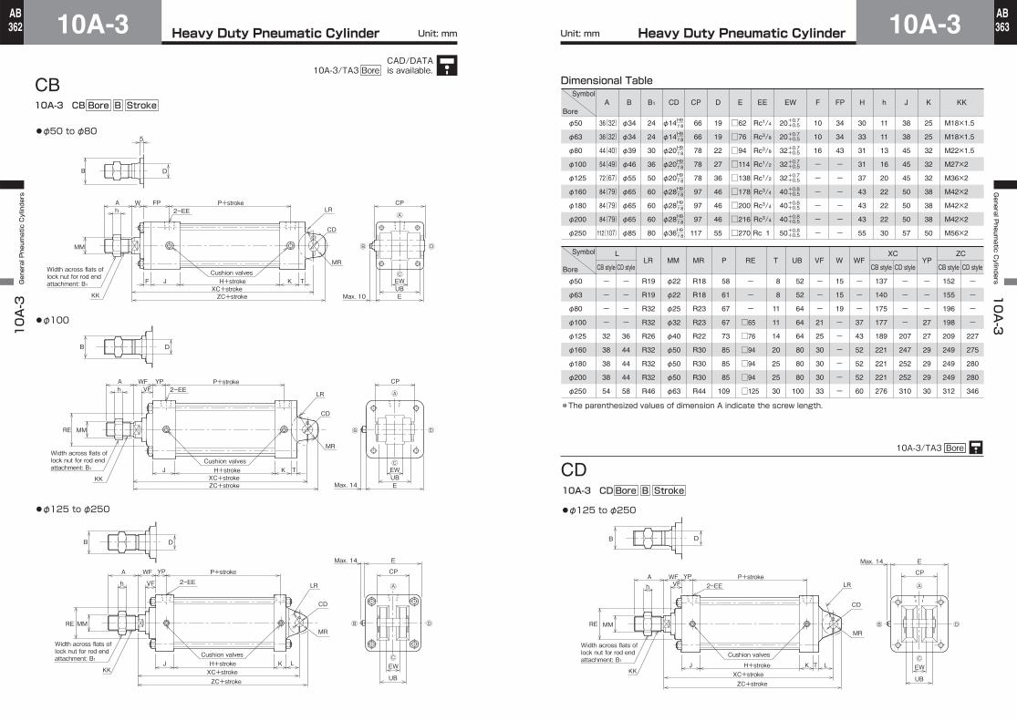
●φ50 to φ80
●φ125 to φ250
CB10A-3 CB Bore B Stroke
●φ100
Dimensional Table
φ22
φ22
φ25
φ32
φ40
φ50
φ50
φ50
φ63
φ34
φ34
φ39
φ46
φ55
φ65
φ65
φ65
φ85
B
24
24
30
36
50
60
60
60
80
B1
19
19
22
27
36
46
46
46
55
D
66
66
78
78
78
97
97
97
117
CP
φ14
φ14
φ20
φ20
φ20
φ28
φ28
φ28
φ36
CD
□62
□76
□94
□114
□138
□178
□200
□216
□270
E
Rc1/4
Rc3/8
Rc3/8
Rc1/2
Rc1/2
Rc3/4
Rc3/4
Rc3/4
Rc 1
EE
20
20
32
32
32
40
40
40
50
EW
10
10
16
-
-
-
-
-
-
F
34
34
43
-
-
-
-
-
-
FP
30
33
31
31
37
43
43
43
55
H
11
11
13
16
20
22
22
22
30
h
38
38
45
45
45
50
50
50
57
J
M18×1.5
M18×1.5
M22×1.5
M27×2
M36×2
M42×2
M42×2
M42×2
M56×2
25
25
32
32
32
38
38
38
50
K KK
MMLR
58
61
67
67
73
85
85
85
109
P
R18
R18
R23
R23
R22
R30
R30
R30
R44
MR
R19
R19
R32
R32
R26
R32
R32
R32
R46
-
-
-
-
32
38
38
38
54
-
-
-
-
36
44
44
44
58
L
-
-
-
21
25
30
30
30
33
VF
8
8
11
11
14
20
25
25
30
T
52
52
64
64
64
80
80
80
100
UBRE
15
15
19
-
-
-
-
-
-
W
-
-
-
37
43
52
52
52
60
WF
-
-
-
27
27
29
29
29
30
YP
137
140
175
177
189
221
221
221
276
-
-
-
-
207
247
252
252
310
CD styleCB style
XC
152
155
196
198
209
249
249
249
312
-
-
-
-
227
275
280
280
346
CD styleCB style
ZC
+0.7+0.5
+0.7+0.5
+0.7+0.5
+0.7+0.5
+0.7+0.5
+0.8+0.5
+0.8+0.5
+0.8+0.5
+0.8+0.5
H9 f 8
H9 f 8
H9 f 8
H9 f 8
H9 f 8
H9 f 8
H9 f 8
H9 f 8
H9 f 8
φ50
φ63
φ80
φ100
φ125
φ160
φ180
φ200
φ250
φ50
φ63
φ80
φ100
φ125
φ160
φ180
φ200
φ250
-
-
-
□65
□76
□94
□94
□94
□125
36(32)
36(32)
44(40)
54(49)
72(67)
84(79)
84(79)
84(79)
112(107)
A
*The parenthesized values of dimension A indicate the screw length.
Ⓓ
Ⓒ
Ⓑ
Ⓐ
RE
ZC+strokeXC+stroke
LTKH+strokeJ
Ah
WF
MM
P+strokeYP
E
CP
UB
EW
Max. 14
B D
KK
2ーEE
Cushion valvesWidth across flats of lock nut for rod end attachment: B1
LR
CD
MR
VF
●φ125 to φ250
CD10A-3/TA3 Bore
Symbol
Bore
Symbol
Bore
10A-3 CD Bore B Stroke
CD styleCB style
Unit: mm Unit: mm
CAD/DATAis available.10A-3/TA3 Bore
Heavy Duty Pneumatic Cylinder10A-310A-3 General Pneumatic Cylinders
364AB
Heavy Duty Pneumatic Cylinder 10A-3General P
neumatic C
ylinders 10A-3
365AB
XG
BBKH+strokeJF
ZB+stroke
Max. 10
TD
TLTMTL
UM
5
B D
P+stroke
MME
TR
Ⓓ
Ⓒ
Ⓑ
Ⓐ
KK
A
h
W FP
2ーEE
Cushion valves
Width across flats of lock nut for rod end attachment: B1
TLTMTL
UM XG
BBKH+strokeJ
ZB+stroke
P+strokeA
h
WF YP
VF 2ーEE
DB
RE
MM
Max. 14
TDE
TR
KK
Ⓓ
Ⓒ
Ⓑ
Ⓐ
Cushion valves
Width across flats of lock nut for rod end attachment: B1
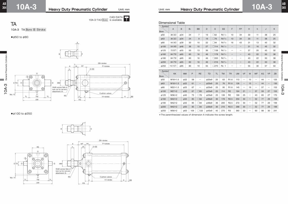
●φ50 to φ80
●φ100 to φ250
TA10A-3 TA Bore B Stroke
Dimensional Table
φ50
φ63
φ80
φ100
φ125
φ160
φ180
φ200
φ250
φ50
φ63
φ80
φ100
φ125
φ160
φ180
φ200
φ250
7
9
10
10
13
16
16
16
19
BB
φ34
φ34
φ39
φ46
φ55
φ65
φ65
φ65
φ85
B
□62
□76
□94
□114
□138
□178
□200
□216
□270
E
Rc1/4
Rc3/8
Rc3/8
Rc1/2
Rc1/2
Rc3/4
Rc3/4
Rc3/4
Rc 1
EE
34
34
43
-
-
-
-
-
-
FP
10
10
16
-
-
-
-
-
-
F
30
33
31
31
37
43
43
43
55
H
11
11
13
16
20
22
22
22
30
h
38
38
45
45
45
50
50
50
57
J
19
19
22
27
36
46
46
46
55
D
25
25
32
32
32
38
38
38
50
K
M18×1.5
M18×1.5
M22×1.5
M27×2
M36×2
M42×2
M42×2
M42×2
M56×2
KK
φ22
φ22
φ25
φ32
φ40
φ50
φ50
φ50
φ63
MM
58
61
67
67
73
85
85
85
109
P
φ25e9
φ25e9
φ25e9
φ25e9
φ25e9
φ36e9
φ36e9
φ36e9
φ45e9
TD
63
76
95
114
139
178
200
216
270
TM
25
25
25
25
25
36
36
36
45
TL
R1.6
R1.6
R1.6
R2
R2
R2.5
R2.5
R2.5
R3
TR
113
126
145
164
189
250
272
288
360
UM
125
130
153
155
170
199
199
199
241
ZB
-
-
-
21
25
30
30
30
33
VF
15
15
19
-
-
-
-
-
-
W
-
-
-
27
27
29
29
29
30
YP
44
44
57
59
65
77
77
77
88
XG
-
-
-
37
43
52
52
52
60
WF
24
24
30
36
50
60
60
60
80
B1
-
-
-
RE
□65
□76
□94
□94
□94
□125
36(32)
36(32)
44(40)
54(49)
72(67)
84(79)
84(79)
84(79)
112(107)
A
*The parenthesized values of dimension A indicate the screw length.
Symbol
Bore
Symbol
Bore
Unit: mm Unit: mm
CAD/DATAis available.10A-3/TA3 Bore
Heavy Duty Pneumatic Cylinder10A-310A-3 General Pneumatic Cylinders
366AB
Heavy Duty Pneumatic Cylinder 10A-3General P
neumatic C
ylinders 10A-3
367AB
DB
5
B D
2-EE
ZB+stroke
A
h
P+strokeFPW
BD
MM
Max. 10
TD
TLTMTL
UM
UW
E
TR
Ⓓ
Ⓒ
Ⓑ
Ⓐ
X1+1/2 stroke=PH
BBKJFKK
Width across flats of lock nut for rod end attachment: B1
H+stroke
Cushion valves
BB
2ーEE
J H+stroke K
ZB+stroke
VF
A
RE
UM
TDUW
TL TLTM
Max. 14Eh
X1+1/2 stroke=PH
WF
MM
BDP+strokeYP
DB
TR
KK
Width across flats of lock nut for rod end attachment: B1
Ⓓ
Ⓒ
Ⓑ
Ⓐ
Cushion valves
●φ50 to φ80
●φ100 to φ250
TC10A-3 TC Bore B Stroke
Dimensional Table
φ34
φ34
φ39
φ46
φ55
φ65
φ65
φ65
φ85
B
24
24
30
36
50
60
60
60
80
B1
7
9
10
10
13
16
16
16
19
BB
30
30
35
40
43
53
53
53
58
BD
19
19
22
27
36
46
46
46
55
D
□62
□76
□94
□114
□138
□178
□200
□216
□270
E
Rc1/4
Rc3/8
Rc3/8
Rc1/2
Rc1/2
Rc3/4
Rc3/4
Rc3/4
Rc 1
EE
10
10
16
-
-
-
-
-
-
F
34
34
43
-
-
-
-
-
-
FP
30
33
31
31
37
43
43
43
55
H
11
11
13
16
20
22
22
22
30
h
38
38
45
45
45
50
50
50
57
J
M18×1.5
M18×1.5
M22×1.5
M27×2
M36×2
M42×2
M42×2
M42×2
M56×2
25
25
32
32
32
38
38
38
50
K KK
φ22
φ22
φ25
φ32
φ40
φ50
φ50
φ50
φ63
MM
58
61
67
67
73
85
85
85
109
P
78
78
98
102
110
129
129
129
146
Min. PH
3
0
7
12
9
13
13
13
6
TC style
min. stroke
126
138
164
182
208
272
300
318
394
UM
71
86
104
128
158
200
228
246
304
UW
-
-
-
21
25
30
30
30
33
VF
25
25
25
25
25
36
36
36
45
TL
76
88
114
132
158
200
228
246
304
TM
R1.6
R1.6
R1.6
R2
R2
R2.5
R2.5
R2.5
R3
TR
φ25e9
φ25e9
φ25e9
φ25e9
φ25e9
φ36e9
φ36e9
φ36e9
φ45e9
TD
15
15
19
-
-
-
-
-
-
W
-
-
-
37
43
52
52
52
60
WF
78
79.5
95.5
97.5
106.5
123.5
123.5
123.5
144.5
XI
-
-
-
27
27
29
29
29
30
YP
125
130
153
155
170
199
199
199
241
ZB
φ50
φ63
φ80
φ100
φ125
φ160
φ180
φ200
φ250
φ50
φ63
φ80
φ100
φ125
φ160
φ180
φ200
φ250
-
-
-
RE
□65
□76
□94
□94
□94
□125
36(32)
36(32)
44(40)
54(49)
72(67)
84(79)
84(79)
84(79)
112(107)
A
*The parenthesized values of dimension A indicate the screw length.
Symbol
Bore
Symbol
Bore
Unit: mm Unit: mm
CAD/DATAis available.10A-3/TA3 Bore
Heavy Duty Pneumatic Cylinder10A-310A-3 General Pneumatic Cylinders
368AB
Heavy Duty Pneumatic Cylinder 10A-3General P
neumatic C
ylinders 10A-3
369AB
X
WW
X
WW
φ50・φ63
φ80
φ100
φ125
φ160・φ180・φ200
φ250
Lock Nut Part Number
Notes) ●Remember that the heat proof field in the table above shows the allowable temperatures for the boots, not for the cylinder.
●Conex is the registered trademark of Teijin Limited.●If the calculated value has a fractional part, round it up.●The boots have been mounted at our factory prior to delivery.●Dimension X is the distance from the cover end. When using the FA accessory, check dimension carefully. (On 50 to 80 mm bore cylinders, the distance is measured from the retainer end face.)●Note that the seal housings of 32 to 80 mm bore cylinders with boots differ from those of standard type cylinders.