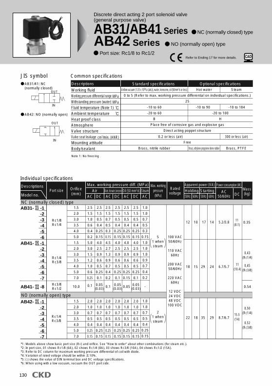
126 Direct acting 2 port solenoid valve (general purpose valve) AB21 Series NC (normally closed) type Port size: Rc1/8, Rc1/4 Individual specifications Flow characteristics Port size Rated voltage Descriptions Model no. Common specifications Descriptions AB21 Working fluid Working pressure differential range Max. working pressure Withstanding pressure (water) Fluid temperature Ambient temperature Heat proof class Atmosphere Valve structure Valve seat leakage Mounting attitude JIS symbol Air, water, oil (50 mm 2 /s or less) 0 to 1.5 (Refer to max. working pressure differential on individual specifications.) 1.5 3 -10 to 40 (no freezing) -20 to 50 B Place free of corrosive gas and explosive gas Direct acting poppet structure 0.2 or less Free 1.5 2.0 3.0 4.0 1.5 2.0 3.0 4.0 Orifice (mm) Rc1/8 Rc1/4 AB21-01-1 AB21-01-2 AB21-01-3 AB21-01-5 AB21-02-1 AB21-02-2 AB21-02-3 AB21-02-5 100 VAC 50/60Hz 110 VAC 60Hz 200 VAC 50/60Hz 220 VAC 60Hz IN OUT 1.5 1.0 0.7 0.4 1.5 1.0 0.7 0.4 1.0 0.6 0.2 0.1 1.0 0.6 0.2 0.1 1.5 1.0 0.4 0.2 1.5 1.0 0.4 0.2 1.0 0.6 0.2 0.1 1.0 0.6 0.2 0.1 0.9 0.5 0.25 0.1 0.9 0.5 0.25 0.1 1.0 0.6 0.2 0.1 1.0 0.6 0.2 0.1 AC DC AC DC AC DC Air Water, kerosene Oil (50 mm 2 /s) Max. working pressure diff. (MPa) 50Hz 11 9 15.4 12.6 5.5/4.2 7 60Hz 50Hz 60Hz DC Power consumption (W) Holding Starting Apparent power (VA) AC 50/60Hz MPa MPa MPa cm 3 /min. (ANR) NC (normally closed) type Model no. Cv flow factor b Flow characteristics Port size Orifice (mm) AB21-01-1 AB21-01-2 AB21-01-3 AB21-01-5 AB21-02-1 AB21-02-2 AB21-02-3 AB21-02-5 Rc 1/8 Rc 1/4 1.5 2.0 3.0 4.0 1.5 2.0 3.0 4.0 0.29 0.53 1.1 1.8 0.29 0.53 1.1 1.8 0.51 0.55 0.52 0.35 0.51 0.55 0.52 0.35 0.1 0.15 0.3 0.4 0.1 0.15 0.3 0.4 C[dm 3 /(s bar)] *1: Effective sectional area S and sonic conductance C are converted as S 5.0 x C.
Transcript
126
Direct acting 2 port solenoid valve(general purpose valve)
AB21 Series NC (normally closed) type Port size: Rc1/8, Rc1/4
Individual specifications
Flow characteristics
Port sizeRated
voltage
Descriptions
Model no.
Common specificationsDescriptions AB21Working fluidWorking pressure differential rangeMax. working pressureWithstanding pressure (water)Fluid temperatureAmbient temperatureHeat proof classAtmosphereValve structureValve seat leakageMounting attitude
JIS symbol
Air, water, oil (50 mm2/s or less)
0 to 1.5 (Refer to max. working pressure differential on individual specifications.)
Refer to page 36 in the introduction for details on the material combinations.
1.5 2 3 4
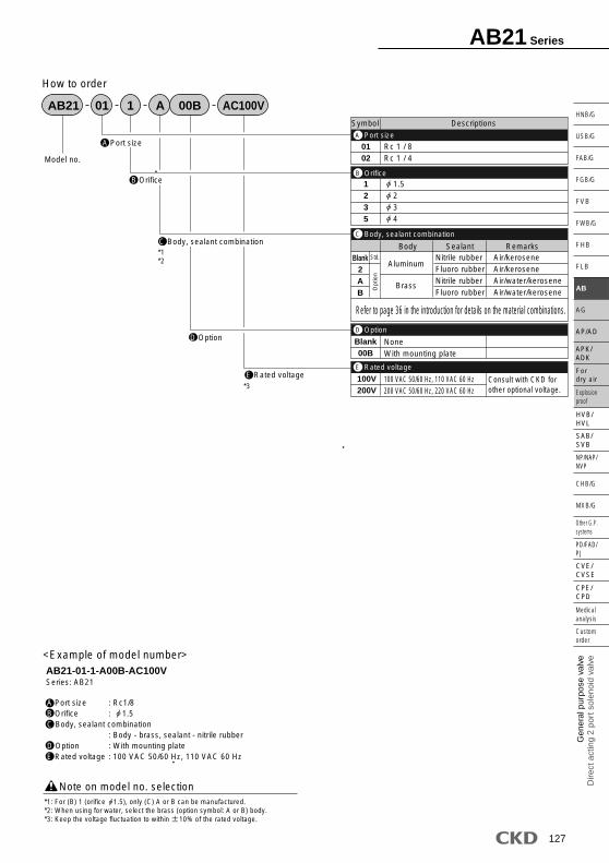
<Example of model number>AB21-01-1-A00B-AC100VSeries: AB21
Note on model no. selection*1: For (B) 1 (orifice 1.5), only (C) A or B can be manufactured.*2: When using for water, select the brass (option symbol: A or B) body.*3: Keep the voltage fluctuation to within 10% of the rated voltage.
A Port size : Rc1/8B Orifice : 1.5C Body, sealant combination
: Body - brass, sealant - nitrile rubberD Option : With mounting plateE Rated voltage : 100 VAC 50/60 Hz, 110 VAC 60 Hz
A
B
C
D
E
Port size
Orifice
Body, sealant combination
Option
Rated voltage
AB21 Series
128
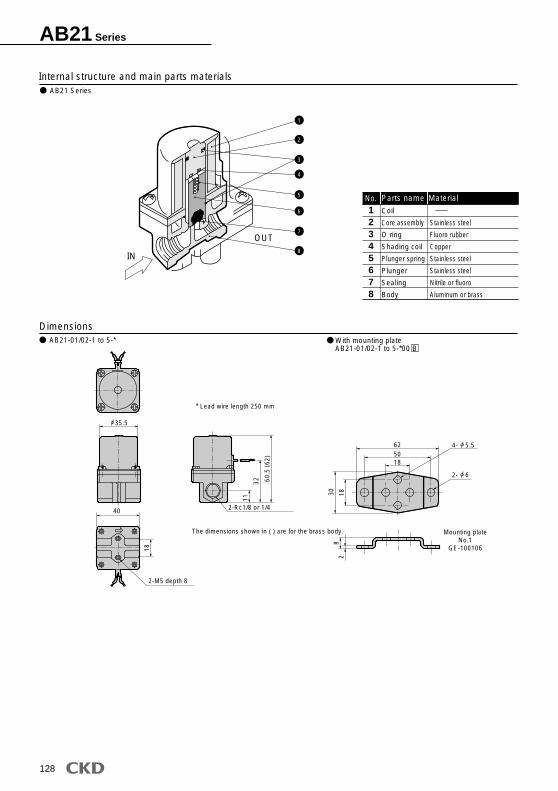
Dimensions AB21-01/02-1 to 5-* With mounting plate
AB21-01/02-1 to 5-*00 B
40
2-M5 depth 8
2-Rc1/8 or 1/4
11
18
32 60.5
(62
)
* Lead wire length 250 mm
The dimensions shown in ( ) are for the brass body.
5062
18
30 182
8
Mounting plateNo.1
GE-100106
Internal structure and main parts materials
Coil
Core assembly
O ring
Shading coil
Plunger spring
Plunger
Sealing
Body
12345678
Parts name
Stainless steel
Fluoro rubber
Copper
Stainless steel
Stainless steel
Nitrile or fluoro
Aluminum or brass
MaterialNo.
IN
OUT
2
1
3
4
5
6
7
8
AB21 Series
35.5
4- 5.5
2- 6
AB31/41/42 Series
130
Common specifications
Descriptions
-10 to 90 -10 to 184
-20 to 100
H
Air/low vacuum (1.33 x 10²Pa (abs)), water, kerosene, oil (50mm2/s or less)
-10 to 60
-20 to 60
B
Standard specifications Optional specifications
Working fluidWorking pressure differential rangeWithstanding pressure (water)Fluid temperature (Note 1)Ambient temperatureHeat proof classAtmosphereValve structureValve seat leakageMounting attitudeBody/sealant
0 to 5 (Refer to max. working pressure differential on individual specifications.)
25
Place free of corrosive gas and explosive gas
Direct acting poppet structure
Free
OUT
IN
OUT
IN
Individual specifications
Port size Ratedvoltage
Max. workingpressure
(MPa)
Descriptions
Model no.
1.5
2.0
3.0
3.5
4.0
5.0
1.5
2.0
3.0
3.5
4.0
5.0
7.0
10.0
1.5
2.0
3.0
3.5
4.0
5.0
7.0
2.5
1.5
0.5
0.4
0.25
0.15
4.0
2.5
0.9
0.6
0.5
0.25
0.1
0.05(0.03)
2.0
1.0
0.7
0.5
0.4
0.25
0.15
2.5
1.5
1.0
0.6
0.4
0.2
5.0
3.0
1.5
1.2
1.0
0.6
0.25
0.1
2.0
1.0
0.7
0.5
0.4
0.25
0.15
2.5
1.5
0.7
0.5
0.3
0.15
4.5
2.7
1.3
0.9
0.7
0.4
0.2
0.1
2.0
1.0
0.7
0.5
0.4
0.25
0.15
2.5
1.5
0.5
0.4
0.25
0.15
4.0
2.5
0.9
0.6
0.5
0.25
0.1
0.05(0.03)
2.0
1.0
0.7
0.5
0.4
0.25
0.15
2.5
1.5
0.5
0.4
0.25
0.15
4.0
2.5
0.9
0.6
0.5
0.25
0.1
0.05(0.03)
2.0
1.0
0.7
0.5
0.4
0.25
0.15
1.0
1.0
0.7
0.5
0.3
0.15
1.0
1.0
1.0
0.9
0.7
0.4
0.2
-
1.0
1.0
0.7
0.5
0.4
0.25
0.15
2.5
1.5
0.5
0.4
0.25
0.15
4.0
2.5
0.9
0.6
0.5
0.25
0.15
0.05
2.0
1.0
0.7
0.5
0.4
0.25
0.15
Orifice(mm)
Rc1/8Rc1/4
Rc3/8Rc1/2
Rc1/4Rc3/8
Rc1/4Rc3/8
100 VAC50/60Hz
110 VAC60Hz
200 VAC50/60Hz
220 VAC60Hz
12 VDC24 VDC48 VDC100 VDC
51 whensteam
AC DC AC DC AC ACDCAir SteamWater, hot water, kerosene Oil (50 mm2/s)
*1: Models above show basic port size (Rc) and orifice. See "How to order" about other combinations (for steam etc.).*2: In port size, 01 shows Rc1/8 (6A), 02 shows Rc1/4 (8A), 03 shows Rc3/8 (10A), 04 shows Rc1/2 (15A). *3: Refer to DC column for maximum working pressure differential of coil with diode. *4: Variation of rated voltage should be within 10%.*5: ( ) shows the value of DIN terminal box and DC voltage specifications. *6: When using with a low vacuum, vacuum the OUT port side.
MPaMPa
cm3/min. (ANR)
Discrete direct acting 2 port solenoid valve(general purpose valve)
Fluid temperature (Note 1)Ambient temperatureValve seat leakage
C[dm3/(s bar)]
*1: Effective sectional area S and sonic conductance C are converted as S 5.0 x C.*2: < > shows values for stainless steel body.
Note 1: No freezingNote 2: The range is -20 to 80 when using the square terminal box with light for the coil housing.
cm3/min. (ANR)
AB31/41/42 Series
132
The combinations indicated with a in the above table can be manufactured.
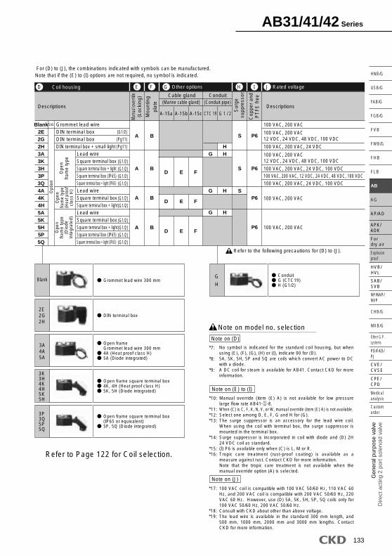
How to order
AB31
AB41
3 0 A B S AC100V3A
0304
0304
3
<Example 1 of model number>
<Example 2 of model number>
*1:
*2:*3:
*4:
*5:
*6:
Body,sealantcombination
Port sizeA
OrificeB
C
Manual override (Locking)
Other options
Copper and PTFE free
Coil housing
Mounting plate
Surge suppressor
VoltageJ
I
G
F
E
D
H
Model no.
G02
*1*2*3*4*5*6
Note on (C)
Note on model no. selection
NC (normally closed)
Standard is blank, however (D), (E), (F), (G), (H) or (I) selected, complete (C) with 0. (D): When selecting 4A, 4K, 4HBronze (standard) body or stainless steel (optional) for low pressure large flow rate AB41- -8.For option symbol V or W, the vacuum inspection is carried out at "leakage: 1.33 x 10
-6Pa m/s or less".
When (C) of low pressure large flow rate AB41- -8 is V or W, DC voltage is not available.The ethylene propylene diene rubber seal combination ((C) P, R) cannot be used with air. (Compressed air contains oil, and ethylene propylene diene rubber is not oil-resistant.)
AB31-02-3-AC100VSeries : AB31A Port size : Rc1/4B Orifice : 3C Body, sealant combination : Body - brass, sealant - nitrile rubberD Coil housing : Grommet lead wireE to I : BlankJ Rated voltage : 100 VAC 50/60 Hz, 110 VAC 60 Hz
AB41-02-3-000AS-AC100VSeries: AB41A Port size : Rc1/4B Orifice : 3C Body, sealant combination : Body - brass, sealant - nitrile rubberD Coil housing : Grommet lead wireE Manual override (Locking) : SelectedF G H : Blank I Surge suppressor : With surge suppressorJ Rated voltage : 100 VAC 50/60 Hz, 110 VAC 60 Hz
Symbol SymbolDescriptions SymbolDescriptions DescriptionsA Port size
Refer to the following page for details on the coil housing,other options and voltage, etc.
Bra
ssS
tain
less
stee
lS
tain
less
stee
lB
rass
BlankBCVDEFWHJKPLMNR
Refer to page 36 in the introduction for details on the material combinations.
1.5 2 3 3.5 4 5 7 10
Air, water, low vacuum, kerosene (up to 60 ) Air, low vacuum, kerosene (up to 90 *2) Steam (up to 184 *2) Medium vacuumAir, water, low vacuum, kerosene (up to 60 ) Air, low vacuum, kerosene (up to 90 *2) Steam (up to 184 *2) Medium vacuumAir, water, low vacuum, kerosene (up to 60 ) Air, low vacuum, kerosene (up to 90 *2) Steam (up to 184 *2) Hot water (up to 90 *2) Air, water, low vacuum, kerosene (up to 60 ) Air, low vacuum, kerosene (up to 90 *2) Steam (up to 184 *2) Hot water (up to 90 *2)
AB31/41/42 Series
133
Gen
eral
pur
pose
val
veD
irect
act
ing
2 po
rt s
olen
oid
valv
e
SAB/SVB
Explosion proof
For dry air
HVB/HVL
NP/NAP/NVP
PD/FAD/PJ
CVE/CVSE
CPE/CPD
Custom order
Medical analysis
Other G.P. systems
HNB/G
USB/G
FAB/G
FGB/G
FVB
FWB/G
FHB
FLB
AB
AG
AP/AD
CHB/G
MXB/G
APK/ADK
2E2G2H
BlankG
H
3A4A5A
3K3H4K4H5K5H
3P3Q5P5Q
Refer to the following precautions for (D) to (J).
*7:
*8:
*9:
*10:
*11:*12:*13:
*14:
*15:*16:
*17:
*18:*19:
Note on (D)
Note on model no. selection
Note on (J)
Note on (E) to (I)
Refer to Page 122 for Coil selection.
No symbol is indicated for the standard coil housing, but when using (E), (F), (G), (H) or (I), indicate 00 for (D).5A, 5K, 5H, 5P and 5Q are coils which convert AC power to DC with a diode.A DC coil for steam is available for AB41. Contact CKD for more information.
100 VAC coil is compatible with 100 VAC 50/60 Hz, 110 VAC 60 Hz, and 200 VAC coil is compatible with 200 VAC 50/60 Hz, 220 VAC 60 Hz. However, use (D) 5A, 5K, 5H, 5P, 5Q coils only for 100 VAC 50/60 Hz, 200 VAC 50/60 Hz.Consult with CKD about other than above voltage. The lead wire is available in the standard 300 mm length, and 500 mm, 1000 mm, 2000 mm and 3000 mm lengths. Contact CKD for more information.
Manual override (item (E) A) is not available for low pressure large flow rate AB41- -8.When (C) is C, F, K, N, V, or W, manual override (item (E) A) is not available.Select one among D, E, F, G and H for (G).The surge suppressor is an accessory for the lead wire coil. When using the coil with terminal box, the surge suppressor is mounted in the terminal box.Surge suppressor is incorporated in coil with diode and (D) 2H 24 VDC coil as standard.(I) P6 is available only when (C) is L, M or R.Tropic care treatment (rust-proof coating) is available as a measure against rust. Contact CKD for more information.Note that the tropic care treatment is not available when the manual override option (A) is selected.
0304
Grommet lead wire 300 mm
DIN terminal box
Open frame Grommet lead wire 300 mm 4A (Heat proof class H) 5A (Diode integrated)
Open frame square terminal box 4K, 4H (Heat proof class H) 5K, 5H (Diode integrated)
Open frame square terminal box (IP65 or equivalent) 5P, 5Q (Diode integrated)
Conduit G (CTC19) H (G1/2)
For (D) to (J), the combinations indicated with symbols can be manufactured.Note that if the (E) to (I) options are not required, no symbol is indicated.
Coil housing
Descriptions Descriptions
Rated voltageOther optionsE F G
A
A
A
A
B S P6
S
S
P6
P6
P6
BD E F
G HH
G H
G H
D E F
D E F
B
B
Grommet lead wireDIN terminal boxDIN terminal boxDIN terminal box + small light
Standard is blank, however (D), (E), (F), (G), (H) or (I) selected, complete (C) with 0.(D): When selecting 4A, 4K, 4HFor option symbol V or W, the vacuum inspection is carried out at "leakage: 1.33 x 10⁻⁶Pa m3/s or less".The ethylene propylene diene rubber seal combination ((C) P, R) cannot be used with air. (Compressed air contains oil, and ethylene propylene diene rubber is not oil-resistant.)
Body, sealant combination
AB42-02-1-AC100VSeries : AB42A Port size : Rc1/4B Orifice : 1.5C Body, sealant combination : Body - brass, sealant - nitrile rubberD Coil housing : Grommet lead wireE to I : BlankJ Rated voltage : 100 VAC 50/60 Hz, 110 VAC 60 Hz
AB42-03-6-000AS-AC100VSeries : AB42A Port size : Rc3/8B Orifice : 5C Body, sealant combination : Body - brass, sealant - nitrile rubberD Coil housing : Grommet lead wireE Manual override (Locking) : SelectedF G : Blank H Surge suppressor : With surge suppressorJ Rated voltage :100 VAC 50/60 Hz, 110 VAC 60 Hz
Refer to the following precautions for (D) to (J).
Refer to Page 122 for Coil selection.
Blank2E2G2H3A3K3H3P3Q4A4K4H5A5K5H5P5Q
For (D) to (J), the combinations indicated with symbols can be manufactured.Note that if the (E) to (I) options are not required, no symbol is indicated.
*5:
*6:
*7:*8:*9:
*10:
*11:*12:
*13:
*14:*15:
Note on (D)
Note on model no. selection
Note on (J)
Note on (E) to (I)
No symbol is indicated for the standard coil housing, but when using (E), (F), (G), (H) or (I), indicate 00 for (D).5A, 5K, 5H, 5P and 5Q are coils which convert AC power to DC with a diode.
100 VAC coil is compatible with 100 VAC 50/60 Hz, 110 VAC 60 Hz, and 200 VAC coil is compatible with 200 VAC 50/60 Hz, 220 VAC 60 Hz. However, use (D) 5A, 5K, 5H, 5P, 5Q coils only for 100 VAC 50/60 Hz, 200 VAC 50/60 Hz.Consult with CKD about other than above voltage. The lead wire is available in the standard 300 mm length, and 500 mm, 1000 mm, 2000 mm and 3000 mm lengths. Contact CKD for more information.
When (C) is C, F, K, N, V, or W, manual override (item (E) A) is not available.Select one among D, E, F, G and H for (G).The surge suppressor is an accessory for the lead wire coil. When using the coil with terminal box, the surge suppressor is mounted in the terminal box.Surge suppressor is incorporated in coil with diode and (D) 2H 24 VDC coil as standard.(I) P6 is available only when (C) is L.Tropic care treatment (rust-proof coating) is available as a measure against rust. Contact CKD for more information.Note that the tropic care treatment is not available when the manual override option (A) is selected.
Conduit G (CTC19) H (G1/2)
Grommet lead wire 300 mm
DIN terminal box
Open frame Grommet lead wire 300 mm 4A (Heat proof class H) 5A (Diode integrated)
Open frame square terminal box 4K, 4H (Heat proof class H) 5K, 5H (Diode integrated)
Open frame square terminal box (IP65 or equivalent) 5P, 5Q (Diode integrated)
Option symbol* For no symbol, O, D, H, L, V or W ···Polyacetal resin : Other than the above··· Stainless steel, perfluoroalkoxy resin
IN OUT
1
2
3
4
9
5
6
7
8
AB31/41/42 Series
138
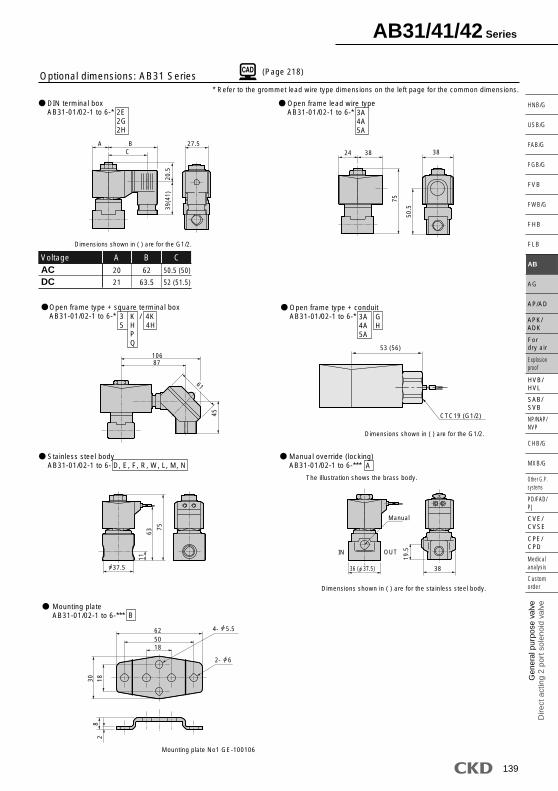
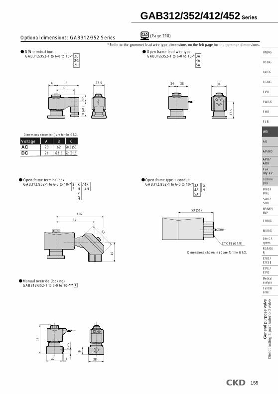
(Page 218)Dimensions: AB31 Series
This AB31 Series, 2 port solenoid valve, open when energized, is designed to meet the customer's requirement according to working fluid, body and seal materials, relation between flow rate and the required pressure (converted to orifice diameter and pressure), and ambient temperature and conditions (converted to coil specifications).
The dimensions are the same for the G or NPT screw port size.
Note 1:
Note 2:
Grommet lead wire type AB31-01, 02-1 to 6
CKD
20 27
36
11
63
75
Rc1/8(01)
Rc1/4(02)
IN OUT
34
28
2-M5 depth 8
18 CKD * Lead wire length 300 mm
AB31/41/42 Series
139
Gen
eral
pur
pose
val
veD
irect
act
ing
2 po
rt s
olen
oid
valv
e
SAB/SVB
Explosion proof
For dry air
HVB/HVL
NP/NAP/NVP
PD/FAD/PJ
CVE/CVSE
CPE/CPD
Custom order
Medical analysis
Other G.P. systems
HNB/G
USB/G
FAB/G
FGB/G
FVB
FWB/G
FHB
FLB
AB
AG
AP/AD
CHB/G
MXB/G
APK/ADK
(Page 218)
* Refer to the grommet lead wire type dimensions on the left page for the common dimensions.
ACDC
A B CVoltage
20
21
50.5 (50)
52 (51.5)
62
63.5
Optional dimensions: AB31 Series
Dimensions shown in ( ) are for the G1/2.
Mounting plate No1 GE-100106
Dimensions shown in ( ) are for the stainless steel body.
2E2G2H
3A4A5A
3 K / 4K5 H 4H P Q
3A4A5A
GH
A
B
DIN terminal boxAB31-01/02-1 to 6-*
Open frame lead wire typeAB31-01/02-1 to 6-*
Open frame type + conduitAB31-01/02-1 to 6-*
Manual override (locking)AB31-01/02-1 to 6-***
Stainless steel bodyAB31-01/02-1 to 6- D, E, F, R, W, L, M, N
Mounting plateAB31-01/02-1 to 6-***
Open frame type + square terminal boxAB31-01/02-1 to 6-*
53 (56)
CTC19 (G1/2)
Dimensions shown in ( ) are for the G1/2.
27.5A BC
39(4
1)20
.5
24 38
75
38
50.5
10687
45
61
1163
75
Manual
38
19.5IN OUT
82
185062
1830
The illustration shows the brass body.
37.5
4- 5.5
2- 6
36 ( 37.5)
AB31/41/42 Series
140
(Page 218)
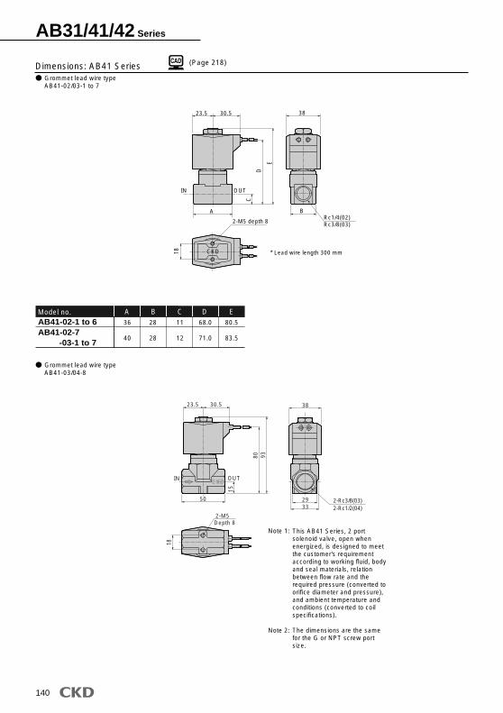
AB41-02-1 to 6AB41-02-7 -03-1 to 7
A B CModel no.36
40
28
28
11
12
D68.0
71.0
E80.5
83.5
Dimensions: AB41 Series
This AB41 Series, 2 port solenoid valve, open when energized, is designed to meet the customer's requirement according to working fluid, body and seal materials, relation between flow rate and the required pressure (converted to orifice diameter and pressure), and ambient temperature and conditions (converted to coil specifications).
The dimensions are the same for the G or NPT screw port size.
Note 1:
Note 2:
23.5 30.5 38
IN OUT
ARc1/4(02)Rc3/8(03)
C
D
E
B
2-M5 depth 8
18 CKD * Lead wire length 300 mm
CKD
23.5 30.5
50
15
80 93
IN OUT
38
2933
2-Rc3/8(03)2-Rc1/2(04)
18
2-M5Depth 8
Grommet lead wire typeAB41-02/03-1 to 7
Grommet lead wire typeAB41-03/04-8
AB31/41/42 Series
141
Gen
eral
pur
pose
val
veD
irect
act
ing
2 po
rt s
olen
oid
valv
e
SAB/SVB
Explosion proof
For dry air
HVB/HVL
NP/NAP/NVP
PD/FAD/PJ
CVE/CVSE
CPE/CPD
Custom order
Medical analysis
Other G.P. systems
HNB/G
USB/G
FAB/G
FGB/G
FVB
FWB/G
FHB
FLB
AB
AG
AP/AD
CHB/G
MXB/G
APK/ADK
(Page 218)
* Refer to the grommet lead wire type dimensions on the left page for the common dimensions.
ACDC
F G HVoltage23.5
23.5
54 (53.5)
54.5 (54)
65.5
66
Dimensions shown in ( ) are for the G1/2.D EModel no.
Note: No manual override available for AB41-03/04-8
Dimensions shown in ( ) are for the stainless steel body.
The illustration shows the brass body.
B
A
GH
3 K / 4K5 H 4H P Q
AB41-02-1 to 6-*AB41-02-7-* -03-1 to 7-*AB41-03/04-8-*
A C D EModel no.11
12
15
68.0
71.0
80
80.5
83.5
93
Stainless steel bodyAB41-02/03/04-1 to 8- D/F/R/W/L/M/N/E
Manual override (locking)AB41-02/03-1 to 7-***
Mounting plateAB41-02/03/04-1 to 8-***
DIN terminal boxAB41-02/03/04-1 to 8-*
Open frame lead wire typeAB41-02/03/04-1 to 8-*
Open frame type + square terminal boxAB41-02/03/04-1 to 8-*
Open frame type + conduitAB41-02/03/04-1 to 8-*
36 ( 37.5)
40 ( 45.0)
* 1: Max. dimension is 54.
37.5
45.0
50*1
AB41-02/03-1 to 7 SeriesStainless steel bodyAB41-02-1 to 6- D/E/F/L/M/N/R/WAB41-03/04-8 SeriesStainless steel bodyAB41-02-7- D/E/F/L/M/N/R/WAB41-03-1 to 7- D/E/F/L/M/N/R/W
AB41-02-1 to 6-* AAB41-02-7-* A -03-1 to 7-* AAB41-03/04-8-* A
57 (60)
CTC19 (G1/2)Dimensions shown in ( ) are for the G1/2.
F GH
27.539
(41)
22
28 42 46
D
E
11091
45
61
A
CD E
IN OUT
A B
K
Manual
62(70)50(58)18(18)
30 188
2
Dimensions in ( ) show value of No.2 mounting plate
Optional dimensions: AB41 Series
4- 5.5
2- 6
CKD
AB31/41/42 Series
142
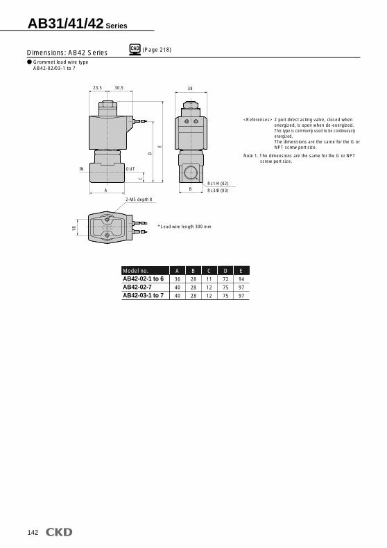
(Page 218)Dimensions: AB42 SeriesGrommet lead wire typeAB42-02/03-1 to 7
AB42-02-1 to 6AB42-02-7AB42-03-1 to 7
A C DModel no.36
40
40
B28
28
28
11
12
12
72
75
75
E94
97
97
23.5 30.5
IN OUT
D
E
C
Rc1/4 (02)
Rc3/8 (03)
38
B
18
2-M5 depth 8
A
CKD * Lead wire length 300 mm
Note 1. The dimensions are the same for the G or NPT screw port size.
2 port direct acting valve, closed when energized, is open when de-energized.This type is commonly used to be continuously energized.The dimensions are the same for the G or NPT screw port size.
<References>
AB31/41/42 Series
143
Gen
eral
pur
pose
val
veD
irect
act
ing
2 po
rt s
olen
oid
valv
e
SAB/SVB
Explosion proof
For dry air
HVB/HVL
NP/NAP/NVP
PD/FAD/PJ
CVE/CVSE
CPE/CPD
Custom order
Medical analysis
Other G.P. systems
HNB/G
USB/G
FAB/G
FGB/G
FVB
FWB/G
FHB
FLB
AB
AG
AP/AD
CHB/G
MXB/G
APK/ADK
(Page 218)
* Refer to the grommet lead wire type dimensions on the left page for the common dimensions.
3 K / 4K5 H 4H P Q
Stainless steel bodyAB42-02/03-1 to 7- D/E/F/R/W/L/M/N
Manual override (locking)AB42-02/03-1 to 7-***
Mounting plateAB42-02/03-1 to 7-***
DIN terminal boxAB42-02/03-1 to 7-*
Open frame lead wire typeAB42-02/03-1 to 7-*
Open frame type + square terminal boxAB42-02/03-1 to 7-*
ModelCodeAB42-02/03-1 to 7 SeriesStainless steel bodyAB42-02-1 to 6- D/E/F/L/M/N/R/WStainless steel bodyAB42-02-7- D/E/F/L/M/N/R/WAB42-03-1 to 7- D/E/F/L/M/N/R/WDimensions in ( ) show value of No.2 mounting plate.
2E2G2H
3A4A5A
Open frame type + conduitAB42-02/03-1 to 7-*
B
A
3A4A5A
GH
57 (60)
CTC19 (G1/2)Dimensions shown in ( ) are for the G1/2.
27.5F G
H
39(4
1)31
28 42
E
D
46
11091
45
61
Manual
(13)
62(70)50(58)
18
4- 5.5
2- 6
82
30 18
ED
C
A
CKD
AB31/41/42 Series
144
Specifications
Flow characteristics
DescriptionsAir, water, kerosene, oil (20 mm2/s)
JIS symbol
Holding (50/60 Hz)Starting (50/60Hz)
Rc1/2
12
Rc3/4
15
Rc1
18
AC: 0 to 100, DC: 0 to 80
AC: 0 to 80, DC: 0 to 80
AC: 0 to 70, DC: 0 to 40
AC: 0 to 50, DC: 0 to 40
AC: 0 to 40, DC: 0 to 30
AC: 0 to 30, DC: 0 to 30
1
20 or less
-5 to 60 (no freezing)
-10 to 60
0.2 or less (air)
Limited to range between vertical mounting with coil section facing upward and horizontal mounting.
*6: Please select one among D, E, F, G and H for (F).
*7: 100 VAC coil is compatible with 100 VAC 50/60 Hz, 110 VAC 60 Hz, and 200 VAC coil is compatible with 200 VAC 50/60 Hz, 220 VAC 60 Hz.
However, use (D) 5A, 5K, 5H coils only for 100 VAC 50/60 Hz, 200 VAC 50/60 Hz.
*8: Consult with CKD about other than above voltage. *9: The lead wire length is available in the standard 300 mm,
and in increments of 500 mm. Contact CKD for more details.
Mou
ntin
gpl
ate
A-15a A-15b A-15c CTC 19
(G1/2)(G1/2)
(G1/2)(G1/2)
Conduit
*2: Refer to Page 122 for Coil selection.*3: 5A, 5K and 5H are coils which convert AC power to
DC with a diode.*4: When working fluid is air, 5A type is recommended. *5: Contact CKD for more details on the heat-resistant
H coil.
Cable gland
*1: Refer to page 36 in the introduction for details on the material combinations.
D E F G
<Example of model number>
Note on model no. selection
Note on (C)
Symbols on (D) to (G) show available combinations.Blank when no item selected from (E) and (F).
Note on (F)
Note on (D) Note on (G)
A Port size: Rc1/2B Orifice: 12C Body, sealant combination : Body - bronze, Stuffing - brass, Sealant - fluoro rubberD Coil housing: DIN terminal box (G1/2)E Mounting plate: SelectedF Other options: BlankG Rated voltage: 100 VAC 50/60 Hz, 110 VAC 60 Hz
A
B
C
Port size
Orifice
Body, sealant combination
AB71 Series
146
(Page 218)
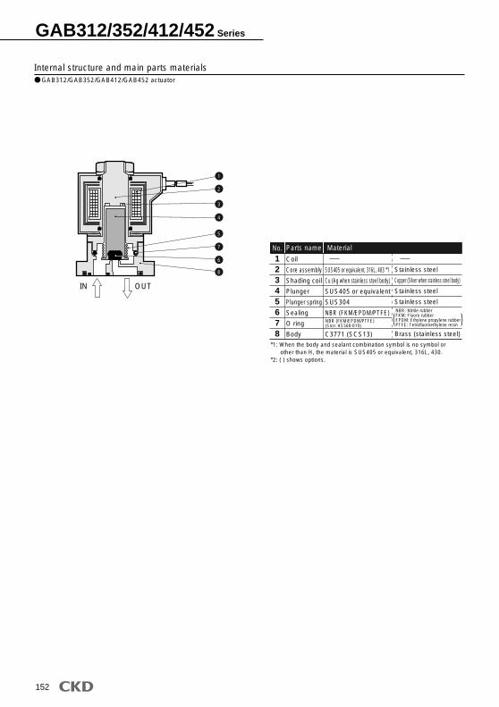
Internal structure and main parts materials
Dimensions
Coil
Plunger
Wearing
Stuffing assembly
(Core assembly)
Spring pin
Main valve
Main valve spring
Body
SUS405
PTFE
C3771
SUS405, Cu
SUS420
SUS304, FKM
SUS304
CAC407
123
4
5678
No. Parts name Material
Stainless steel
Tetrafluoroethylene resin
Brass
Stainless steel, copper
Stainless steel
Stainless steel, fluoro rubber
Stainless steel
Bronze
71
80
90
14.5
17.5
22.5
95
101
111
110.5
116
126
50
60
71
Rc1/2
Rc3/4
Rc1
56
63
75
45
50
56
40
45
50
9
9
11
AB71-15-12AB71-20-15AB71-25-18
A B C D E F G H J KModel no.
Grommet lead wire typeAB71-*-*-*2C
With mounting plateAB71-*-*-** B
OUTIN
A
30 38 (300)
BC D
48
E F
CKDCKD
G
J
2-K
3.2
H
1
2
3
4
5
6
7
8
AB71Series
147
Gen
eral
pur
pose
val
veD
irect
act
ing
2 po
rt s
olen
oid
valv
e
SAB/SVB
Explosion proof
For dry air
HVB/HVL
NP/NAP/NVP
PD/FAD/PJ
CVE/CVSE
CPE/CPD
Custom order
Medical analysis
Other G.P. systems
HNB/G
USB/G
FAB/G
FGB/G
FVB
FWB/G
FHB
FLB
AB
AG
AP/AD
CHB/G
MXB/G
APK/ADK
CKD
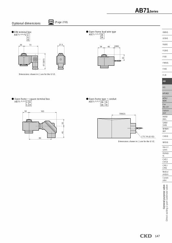
(Page 218)Optional dimensions
DIN terminal boxAB71-*-*-*2
Open frame lead wire typeAB71-*-*-*
Open frame + square terminal boxAB71-*-*-*
EGH
3A5A
3 K5 H
Open frame type + conduitAB71-*-*-* 3A
5AGH
Dimensions shown in ( ) are for the G1/2.
30 73 27.561
.5(6
1)
34 46 (300)
33
34 103
84
3345
Dimensions shown in ( ) are for the G1/2.
59(62)
CTC19 (G1/2)
148
Common specificationsDescriptions
-20 to 100
H
Air/low vacuum (1.33 x 10²Pa (abs)), water, kerosene, oil (50mm2/s or less)
-10 to 60
-20 to 60
B
Standard specifications Optional specifications
MPaMPaMPa
cm3/min. (ANR)
Working fluidWorking pressure differential rangeMax. working pressureWithstanding pressure (water)Fluid temperature (Note 1)Ambient temperatureHeat proof classAtmosphereValve structureValve seat leakageMounting attitudeBody/sealant
JIS symbol
0 to 5 (Refer to max. working pressure differential on individual specifications.)
10
Place free of corrosive gas and explosive gas
Direct acting poppet structure
Free
GAB352/452(Individual supply/Port A pressurized)
Individual specifications
Portsize Rated voltageModel no.
1.5
2.0
3.0
3.5
4.0
5.0
1.5
2.0
3.0
3.5
4.0
5.0
7.0
2.5
1.5
0.5
0.4
0.25
0.15
4.0
2.5
0.9
0.6
0.5
0.25
0.1
2.5
1.5
1.0
0.6
0.4
0.2
5.0
3.0
1.5
1.2
1.0
0.6
0.25
2.5
1.5
0.7
0.5
0.3
0.15
4.5
2.7
1.3
0.9
0.7
0.4
0.2
2.5
1.5
0.5
0.4
0.25
0.15
4.0
2.5
0.9
0.6
0.5
0.25
0.1
2.5
1.5
0.5
0.4
0.25
0.15
4.0
2.5
0.9
0.6
0.5
0.25
0.1
1.0
1.0
0.7
0.5
0.3
0.15
1.0
1.0
1.0
0.9
0.7
0.4
0.2
2.5
1.5
0.5
0.4
0.25
0.15
4.0
2.5
0.9
0.6
0.5
0.25
0.15
Orifice(mm)
GAB312/352-1-2-3-4-5-6
GAB412/452-1-2-3-4-5-6-7
100 VAC50/60Hz
110 VAC60Hz
200 VAC50/60Hz
220 VAC60Hz
12 VDC24 VDC48 VDC100 VDC
AC DC AC DC AC ACDCAir SteamWater, hot water, kerosene Oil (50 mm2/s)
Max. working pressure diff. (MPa)
50Hz
12 10 17 14 5.2/3.8 11(8.1)
18 15 29 24 6.7/5.711
(10.4)
60Hz 50Hz 60HzDC
Power consumption (W)Holding Starting
Apparent power (VA)
AC50/60Hz
*1: Models above shows basic orifice. See "How to order" about other combinations (for steam etc.).*2: Refer to How to order (page 150) and Dimensions (page 154) for port size.*3: Refer to DC column for maximum working pressure differential of coil with diode. *4: Variation of rated voltage should be within 10%.*5: ( ) shows the value of DIN terminal box and DC voltage specifications. *6: When using with the low vacuum, vacuum the NO port side.
Direct acting 2 port solenoid valve, manifold/actuator(general purpose valve)
GAB312/GAB352/GAB412/GAB452 Series NC (normally closed) type Common supply type (C port pressurization), individual supply type (A port pressurization)
Fluid temperature (Note 1)Ambient temperatureValve seat leakage
Note 1: No freezingNote 2: The range is -20 to 80 when using the square terminal box with light for the coil housing.
cm3/min. (ANR)
1.5
2.0
3.0
3.5
4.0
5.0
1.5
2.0
3.0
3.5
4.0
5.0
7.0
0.29
0.53
1.1
1.5
1.9
2.6
0.29
0.53
1.1
1.5
1.9
2.6
4.6
0.53
0.52
0.52
0.47
0.47
0.38
0.53
0.5
0.52
0.47
0.47
0.38
0.37
0.10
0.15
0.31
0.40
0.48
0.62
0.10
0.15
0.31
0.40
0.48
0.62
0.82
-1-2-3-4-5-6-1-2-3-4-5-6-7
GAB312·352
GAB412·452
-
-
Model no.b
Flow characteristicsPort size Orifice
(mm) C[dm3/(s·bar)] Cv flow factor
*1: Effective sectional area S and sonic conductance C are converted as S 5.0 x C.
GAB312/352/412/452 Series
150
The combinations indicated with a in the above table can be manufactured.
How to orderCommon supply type(Port C pressurized)
Individual supply type (Port A pressurized)
Common supply type(Port C pressurized)
Individual supply type(Port A pressurized)
Discrete masking plate and sub-plate are available.
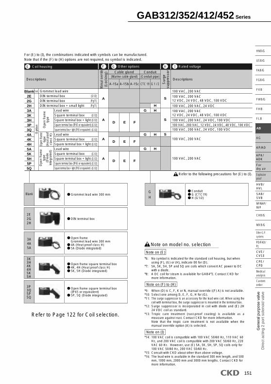
Consult with CKD about more than 11 stations manifold.Standard is blank, however (E), (F), (G) or (H) selected, complete (D) with 0. (D): When selecting 4A, 4K, 4HThe ethylene propylene diene rubber seal combination ((D) P, R) cannot be used with air.(Compressed air contains oil, and ethylene propylene diene rubber is not oil-resistant.)
*1:
*2:*3:
*4:*5:
Note on model no. selection
Note on (C) to (D)
GAB312G-1-3-AC200VSeries : GAB312 (common supply type port C pressurization)A Type of thread: GB Orifice : 1.5C Station no. : 3 stationsD Body, sealant combination : Body - brass, sealant - nitrile rubberE Coil housing : Grommet lead wireF to H : BlankG Rated voltage : 200 VAC 50/60 Hz, 220 VAC 60 Hz
GAB352-5-2-000AS-AC200VSeries: GAB352 (individual supply type port A pressurization)A Type of thread : Rc B Orifice : 4C Station no. : 2 stationsD Body, sealant combination : Body - brass, sealant - nitrile rubberE Coil housing : Grommet lead wireF Manual override (locking) : SelectedG Other options : BlankH Surge suppressor : With surge suppressor I Rated voltage : 200 VAC 50/60 Hz, 220 VAC 60Hz
<Example 1 of model number>
<Example 2 of model number>
GAB312
GAB352
GAB412
GAB452
Model no.
1 B A G S AC100V4A
Manual override (Locking)
Other options
Voltage
Body,sealantcombination*3*4*5
A
B
5
C
E
F
G
I
H
Station no.*2
Orifice
D
Surge suppressorCoil housing
Type of screw
Model no.
GAB312GAB352
GAB412GAB452
Symbol Descriptions
BlankGN
RcGNPT
1234567
1.5233.5457
to to2 stations
10 stationsActuator only
2
100
E Ito
Refer to the following page for details on the coil housing,other options and voltage, etc.
Refer to the following precautions for (E) to (I).
Grommet lead wire 300 mm
DIN terminal box
Open frame Grommet lead wire 300 mm4A (Heat proof class H)5A (Diode integrated)
ConduitG (CTC19)H (G1/2)
Open frame square terminal box4K, 4H (Heat proof class H)5K, 5H (Diode integrated)
Refer to Page 122 for Coil selection.
Open frame square terminal box(IP65 or equivalent)5P, 5Q (Diode integrated)
For (E) to (I), the combinations indicated with symbols can be manufactured.Note that if the (F) to (H) options are not required, no symbol is indicated.
Blank2E2G2H3A3K3H3P3Q4A4K4H5A5K5H5P5Q
*6:
*7:
*8:
*9:*10:*11:
*12:
*13:
*14:
*15:*16:
Note on (E)
Note on model no. selection
Note on (I)
Note on (F) to (H)
No symbol is indicated for the standard coil housing, but when using (F), (G) or (H), indicate 00 for (D).5A, 5K, 5H, 5P and 5Q are coils which convert AC power to DC with a diode.A DC coil for steam is available for GAB4*2. Contact CKD for more information.
100 VAC coil is compatible with 100 VAC 50/60 Hz, 110 VAC 60 Hz, and 200 VAC coil is compatible with 200 VAC 50/60 Hz, 220 VAC 60 Hz. However, use (E) 5A, 5K, 5H, 5P, 5Q coils only for 100 VAC 50/60 Hz, 200 VAC 50/60 Hz.Consult with CKD about other than above voltage. The lead wire is available in the standard 300 mm length, and 500 mm, 1000 mm, 2000 mm and 3000 mm lengths. Contact CKD for more information.
When (D) is C, F, K or N, manual override ((F) A) is not available.Select one among D, E, F, G, H for (G).The surge suppressor is an accessory for the lead wire coil. When using the coil with terminal box, the surge suppressor is mounted in the terminal box.Surge suppressor is incorporated in coil with diode and (E) 2H 24 VDC coil as standard.Tropic care treatment (rust-proof coating) is available as a measure against rust. Contact CKD for more information.Note that the tropic care treatment is not available when the manual override option (A) is selected.
GAB312/352/412/452 Series
152
1234
Internal structure and main parts materials GAB312/GAB352/GAB412/GAB452 actuator
(Page 218)Dimensions: GAB312/352 SeriesManifold (grommet lead wire)GAB312/352-1 to 6- 2 to 10
Actuator (grommet lead wire)GAB312/352-1 to 6- 0
How to mount actuator
23456
AA BBStation number106
145
212
223
290
122
161
228
239
306
Manifold structure2 stations x 1
3 stations x 1
2 stations x 2
5 stations x 1
3 stations x 2
78910
AA BBStation number329
368
435
446
345
384
451
462
Manifold structure5 stations + 2 stations
5 stations + 3 stations
3 stations x 3
5 stations x 2
Consult with CKD about more than 11 stations.
*1: Manifold structured by basic combination of 2, 3 and 5 stations.*2: The dimensions are the same for the G or NPT thread port size.
This machining drawing applies when using two actuators.
20 27
42
25.5
84 96
22
2-Rc3/8(Port C)
8
8
10242
33 39
8
AA
BB
4
7
30
n-Rc1/4
(Port A)
20 27
42
4.5
50
62
34
38
287
328.
56
13
7
GAB352
4- 4.5
4 depth 3.7GAB312
39 and over
Port C side
Port A side 2-n- 7.5
2 x 2n-M4Effective thread depth 6 and over
n- 3 depth 3 0.37 0.2 7 0.2
28 0.2 28 0.2
17 0
.1
32
0.1
+0.1 0
(n indicates a station number.)
GAB312/352/412/452 Series
155
Gen
eral
pur
pose
val
veD
irect
act
ing
2 po
rt s
olen
oid
valv
e
SAB/SVB
Explosion proof
For dry air
HVB/HVL
NP/NAP/NVP
PD/FAD/PJ
CVE/CVSE
CPE/CPD
Custom order
Medical analysis
Other G.P. systems
HNB/G
USB/G
FAB/G
FGB/G
FVB
FWB/G
FHB
FLB
AB
AG
AP/AD
CHB/G
MXB/G
APK/ADK
(Page 218)
* Refer to the grommet lead wire type dimensions on the left page for the common dimensions.
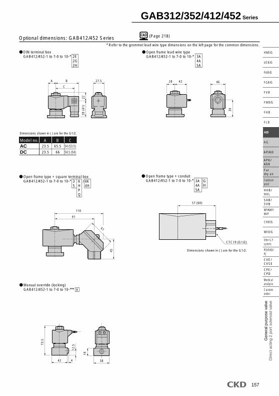
Optional dimensions: GAB312/352 Series
DIN terminal boxGAB312/352-1 to 6-0 to 10-* 2E
2G2H
Open frame lead wire typeGAB312/352-1 to 6-0 to 10-* 3A
4A5A
Open frame terminal boxGAB312/352-1 to 6-0 to 10-*
Manual override (locking)GAB312/352-1 to 6-0 to 10-***
Dimensions shown in ( ) are for the G1/2.
ACDC
A B CVoltage20
21
62
63.5
50.5 (50)
52 (51.5)
Open frame type + conduitGAB312/352-1 to 6-0 to 10-*
A
3A4A5A
3 K / 4K5 H 4H P Q
GH
53 (56)
CTC19 (G1/2)
Dimensions shown in ( ) are for the G1/2.
A
C
B39
(41
)20
.527.5 24 38
37.5
38
106
87
61
45
68
12.5
442
19
38
GAB312/352/412/452 Series
156
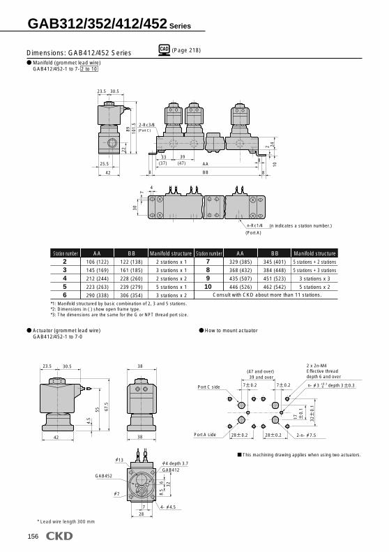
(Page 218)Dimensions: GAB412/452 SeriesManifold (grommet lead wire)GAB412/452-1 to 7- 2 to 10
Actuator (grommet lead wire)GAB412/452-1 to 7-0
How to mount actuator
23456
AA BBStation number106 (122)
145 (169)
212 (244)
223 (263)
290 (338)
122 (138)
161 (185)
228 (260)
239 (279)
306 (354)
Manifold structure2 stations x 1
3 stations x 1
2 stations x 2
5 stations x 1
3 stations x 2
*1: Manifold structured by basic combination of 2, 3 and 5 stations.*2: Dimensions in ( ) show open frame type.*3: The dimensions are the same for the G or NPT thread port size.
78910
AA BBStation number329 (385)
368 (432)
435 (507)
446 (526)
345 (401)
384 (448)
451 (523)
462 (542)
Manifold structure5 stations + 2 stations
5 stations + 3 stations
3 stations x 3
5 stations x 2
Consult with CKD about more than 11 stations.
This machining drawing applies when using two actuators.
23.5
25.5
30.5
42
89 101.
5
222-Rc3/8(Port C)
8
8
10242
33 39
8
AA
BB
4
7
30
n-Rc1/4
(Port A)
(37) (47)
23.5 30.5
42
4.5
55 67.5
38
38
28
7
32
8.5
6
13
7
GAB452
4- 4.5
4 depth 3.7GAB412
* Lead wire length 300 mm
39 and over(47 and over)
Port C side
Port A side 2-n- 7.5
2 x 2n-M4Effective threaddepth 6 and over
n- 3 depth 3 0.37 0.2 7 0.2
28 0.2 28 0.2
17 0
.1
32
0.1
+0.1 0
(n indicates a station number.)
GAB312/352/412/452 Series
157
Gen
eral
pur
pose
val
veD
irect
act
ing
2 po
rt s
olen
oid
valv
e
SAB/SVB
Explosion proof
For dry air
HVB/HVL
NP/NAP/NVP
PD/FAD/PJ
CVE/CVSE
CPE/CPD
Custom order
Medical analysis
Other G.P. systems
HNB/G
USB/G
FAB/G
FGB/G
FVB
FWB/G
FHB
FLB
AB
AG
AP/AD
CHB/G
MXB/G
APK/ADK
(Page 218)
* Refer to the grommet lead wire type dimensions on the left page for the common dimensions.
Optional dimensions: GAB412/452 Series
DIN terminal boxGAB412/452-1 to 7-0 to 10-* 2E
2G2H
Open frame lead wire typeGAB412/452-1 to 7-0 to 10-* 3A
4A5A
Open frame type + square terminal boxGAB412/452-1 to 7-0 to 10-*
Manual override (locking)GAB412/452-1 to 7-0 to 10-***
ACDC
A B CModel no.23.5
23.5
65.5
66
54 (53.5)
54.5 (54)
Dimensions shown in ( ) are for the G1/2.
A
Open frame type + conduitGAB412/452-1 to 7-0 to 10-* 3A
AC DC AC DC AC ACDCAir SteamWater, hot water, kerosene Oil (50 mm2/s)
Max. working pressure diff. (MPa)
50Hz
22 18 35 29 8.7/6.7 15.5(14)
60Hz 50Hz 60HzDC
Power consumption (W)Holding Starting
Apparent power (VA)
AC50/60Hz
*1: Models above shows basic orifice. Refer to How to order about other combinations.*2: Refer to How to order (page 160) and Dimensions (page 164) for port size.*3: Variation of rated voltage should be within 10%.*4: ( ) shows DC DIN terminal box specifications.*5: Refer to DC column for maximum working pressure differential of coil with diode.*6: When using with a low vacuum, vacuum the OUT port side.
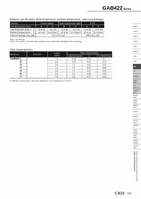
GAB422(Common supply/Port C pressurized)
IN
OUT
IN
OUT
Port A Port A
Port C
Descriptions
-20 to 100
H
Air/low vacuum (1.33 x 10²Pa (abs)), water, kerosene, oil (50mm2/s or less)
-10 to 60
-20 to 60
B
Standard specifications Optional specifications
MPaMPaMPa
cm3/min. (ANR)
Working fluidWorking pressure differential rangeMax. working pressureWithstanding pressure (water)Fluid temperature (Note 1)Ambient temperatureHeat proof classAtmosphereValve structureValve seat leakageMounting attitudeBody/sealant
0 to 2 (Refer to max. working pressure differential on individual specifications.)
Note 1: No freezingNote 2: The range is -20 to 80 when using the square terminal box with light for the coil housing.
-10 to 90
-20 to 100 (Note 2)
1.5
2.0
3.0
3.5
4.0
5.0
7.0
0.29
0.53
1.1
1.5
1.9
2.6
4.6
0.53
0.52
0.52
0.47
0.47
0.38
0.37
0.1
0.15
0.31
0.40
0.47
0.62
0.82
GAB422-1-2-3-4-5-6-7
-
Model no.C[dm3/(s·bar)] Cv flow factorb
Flow characteristicsPort size Orifice
(mm)
Sealant
Coil (heat proof class)-10 to 60
-20 to 60
-10 to 90
-20 to 100 (Note 2)
-10 to 60
-20 to 60
0.2 or less (air) 300 or less (air)
-10 to 60
-20 to 60
-10 to 184
-20 to 100 (Note 2)
Fluoro rubber
B H B H B H
Ethylene propylene diene rubber PTFE
cm3/min. (ANR)
Fluid temperature (Note 1)Ambient temperatureValve seat leakage
*1: Effective sectional area S and sonic conductance C are converted as S 5.0 x C.
GAB422 Series
160
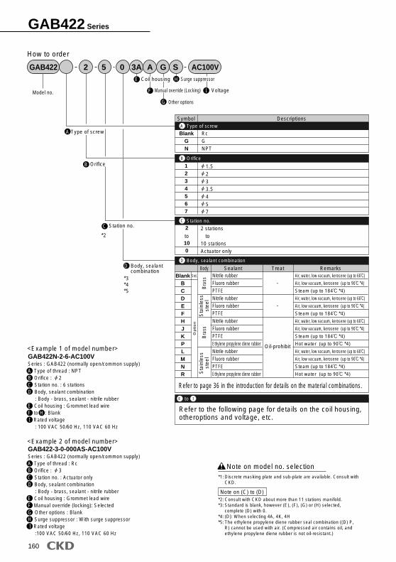
Station no.
B
GAB422 2 5 A G S AC100V3A
How to order
1.5233.5457
to to
Model no. Manual override (Locking)
Surge suppressorCoil housing
Other options
Voltage
Body, sealantcombination
Type of screwA
Orifice
C
0
D
E
F
G
I
H
<Example 1 of model number>
<Example 2 of model number>
1234567
2 stations
10 stationsActuator only
2
100
*2
*3*4*5
Note on (C) to (D)
Discrete masking plate and sub-plate are available. Consult with CKD.
Consult with CKD about more than 11 stations manifold.Standard is blank, however (E), (F), (G) or (H) selected, complete (D) with 0. (D): When selecting 4A, 4K, 4HThe ethylene propylene diene rubber seal combination ((D) P, R) cannot be used with air. (Compressed air contains oil, and ethylene propylene diene rubber is not oil-resistant.)
*1:
*2:*3:
*4:*5:
Note on model no. selection
GAB422-3-0-000AS-AC100VSeries : GAB422 (normally open/common supply)A Type of thread : Rc B Orifice : 3C Station no. : Actuator onlyD Body, sealant combination : Body - brass, sealant - nitrile rubberE Coil housing : Grommet lead wireF Manual override (locking): SelectedG Other options : BlankH Surge suppressor : With surge suppressor I Rated voltage :100 VAC 50/60 Hz, 110 VAC 60 Hz
GAB422N-2-6-AC100VSeries : GAB422 (normally open/common supply)A Type of thread : NPT B Orifice : 2C Station no. : 6 stationsD Body, sealant combination : Body - brass, sealant - nitrile rubberE Coil housing : Grommet lead wireF to H : Blank I Rated voltage : 100 VAC 50/60 Hz, 110 VAC 60 Hz
For (E) to (I), the combinations indicated with symbols can be manufactured.Note that if the (F) to (H) options are not required, no symbol is indicated.
2E2G2H
BlankG
H
3A4A5A
3K3H4K4H5K5H
3P3Q5P5Q
Refer to the following precautions for (E) to (I).
Grommet lead wire 300 mm
DIN terminal box
Open frame Grommet lead wire 300 mm4A (Heat proof class H)5A (Diode integrated)
ConduitG (CTC19)H (G1/2)
Open frame square terminal box4K, 4H (Heat proof class H)5K, 5H (Diode integrated)
Refer to Page 122 for Coil selection.
Open frame square terminal box(IP65 or equivalent)5P, 5Q (Diode integrated)
*6:
*7:
*8:*9:*10:
*11:
*12:
*13:
*14:*15:
Note on (E)
Note on model no. selection
Note on (I)
Note on (F) to (H)
No symbol is indicated for the standard coil housing, but when using (F), (G) or (H), indicate 00 for (D).5A, 5K, 5H, 5P and 5Q are coils which convert AC power to DC with a diode.
100 VAC coil is compatible with 100 VAC 50/60 Hz, 110 VAC 60 Hz, and 200 VAC coil is compatible with 200 VAC 50/60 Hz, 220 VAC 60 Hz. However, use (E) 5A, 5K, 5H, 5P, 5Q coils only for 100 VAC 50/60 Hz, 200 VAC 50/60 Hz.Consult with CKD about other than above voltage. The lead wire is available in the standard 300 mm length, and 500 mm, 1000 mm, 2000 mm and 3000 mm lengths. Contact CKD for more information.
When (D) is C, F, K or N, manual override ((F) A) is not available.Select one among D, E, F, G, H for (G).The surge suppressor is an accessory for the lead wire coil. When using the coil with terminal box, the surge suppressor is mounted in the terminal box.Surge suppressor is incorporated in coil with diode and (E) 2H 24 VDC coil as standard.Tropic care treatment (rust-proof coating) is available as a measure against rust. Contact CKD for more information.Note that the tropic care treatment is not available when the manual override option (A) is selected.
GAB422 Series
162
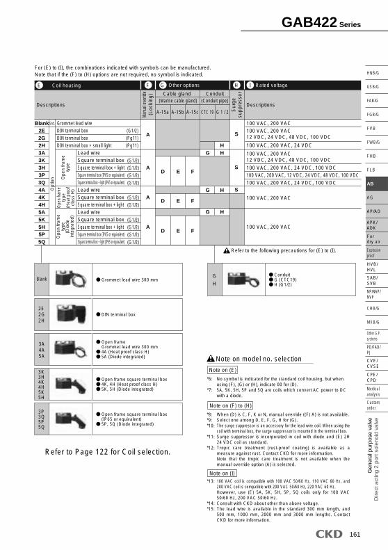
Core assembly
Coil
Plunger
Shading coil
Sealing
O ring
Spring
Parts name
SUS405 or equivalent, 316L, 304
SUS405 or equivalent
Cu (Ag when stainless steel body)
NBR (FKM/EPDM/PTFE)
SUS304
Stainless steel
Stainless steel
Copper (Silver when stainless steel body)
Stainless steel
MaterialNo.
Internal structure and main parts materialsGAB422 actuator
Option symbol* For no symbol, O, D, H or L ···Polyacetal resin : Other than the above ···Stainless steel, perfluoroalkoxy resin
GAB422 manifold
( )
9
1
2
3
4
5
6
7
8
10
11
12
13
GAB422 Series
164
(Page 218)
(Page 218)
Dimensions: ManifoldGrommet lead wire typeGAB422-1 to 7- 2 to 10
23456
AA BBStation number106 (122)
145 (169)
212 (244)
223 (263)
290 (338)
122 (138)
161 (185)
228 (260)
239 (279)
306 (354)
Manifold structure2 stations x 1
3 stations x 1
2 stations x 2
5 stations x 1
3 stations x 2
789
10
AA BBStation number329 (385)
368 (432)
435 (507)
446 (526)
345 (401)
384 (448)
451 (523)
462 (542)
Manifold structure5 stations + 2 stations
5 stations + 3 stations
3 stations x 3
5 stations x 2
Consult with CKD about more than 11 stations.
*1: Manifold structured by basic combination of 2, 3 and 5 stations.*2: Dimensions in ( ) show open frame type.*3: When GAB422 DIN terminal box and DC voltage, apply open frame dimensions.
*4: The dimensions are the same for the G or NPT thread port size.
Dimensions: ActuatorGrommet lead wire typeGAB422-1 to 7- 0
How to mount actuator
30.523.5 38
42
59
81
4.5
38
13
7
728
4- 4.5
328.
56
4 depth 3.7
* Lead wire length 300 mm
Port A side
This machining drawing applies when using two actuators.
28 0.2 28 0.2 2-n- 7.5
17
0.1
32
0.1
Port C side
(47 and over)39 and over
7 0.2 7 0.2 n- 3
Effective threaddepth 6 and over
2 x 2n-M4
0+0.1 depth 3 0.3
42
(Port C)
23.5
25.5
30.5
115
9322
(Port A)
8
33 39AA(37) (47)
BB
10
224
2-Rc3/8
n-Rc1/4
307
4
(n indicates a station number.)
GAB422 Series
165
Gen
eral
pur
pose
val
veD
irect
act
ing
2 po
rt s
olen
oid
valv
e
SAB/SVB
Explosion proof
For dry air
HVB/HVL
NP/NAP/NVP
PD/FAD/PJ
CVE/CVSE
CPE/CPD
Custom order
Medical analysis
Other G.P. systems
HNB/G
USB/G
FAB/G
FGB/G
FVB
FWB/G
FHB
FLB
AB
AG
AP/AD
CHB/G
MXB/G
APK/ADK
(Page 218)
* Refer to the grommet lead wire type dimensions on the left page for the common dimensions.
Optional dimensions
Open frame type + square terminal boxGAB422-1 to 7-0 to 10-*
Manual override (locking)GAB422-1 to 7-0 to 10-***
DIN terminal boxGAB422-1 to 7-0 to 10-* 2E
2G2H
Open frame lead wire typeGAB422-1 to 7-0 to 10-* 3A
4A5A
ACDC
A B C DVoltage23.5
28
65.5
72
54 (53.5)
60.5 (60)
38
46
Dimensions shown in ( ) are for the G1/2.
A
Open frame type + conduitGAB422-1 to 7-0 to 10-* 3A