ME 455/555 Intro to Finite Element Analysis Fall 2016 Abaqus/CAE Axisymmetric tutorial
©2016 Hormoz Zareh 1 Portland State University, Mechanical Engineering
Abaqus/CAEAxisymmetricTutorial(Version2016)
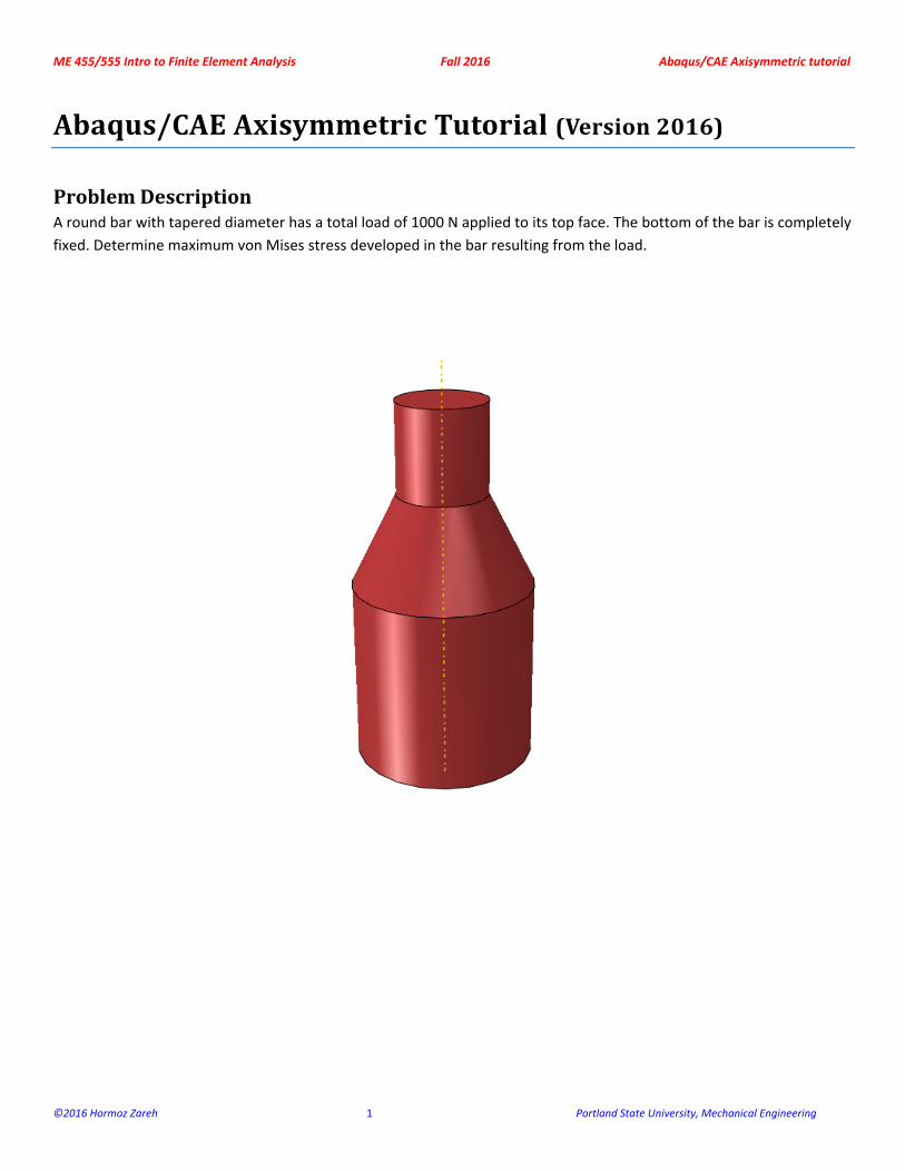
ProblemDescriptionA round bar with tapered diameter has a total load of 1000 N applied to its top face. The bottom of the bar is completely
fixed. Determine maximum von Mises stress developed in the bar resulting from the load.
ME 455/555 Intro to Finite Element Analysis Fall 2016 Abaqus/CAE Axisymmetric tutorial
©2016 Hormoz Zareh 2 Portland State University, Mechanical Engineering
AnalysisSteps1. Start Abaqus and choose to create a new model database
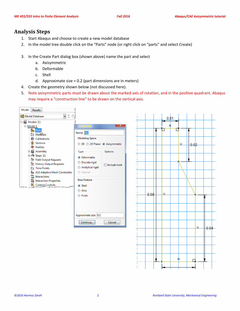
2. In the model tree double click on the “Parts” node (or right click on “parts” and select Create)
3. In the Create Part dialog box (shown above) name the part and select
a. Axisymmetric
b. Deformable
c. Shell
d. Approximate size = 0.2 (part dimensions are in meters)
4. Create the geometry shown below (not discussed here).
5. Note axisymmetric parts must be drawn about the marked axis of rotation, and in the positive quadrant. Abaqus
may require a “construction line” to be drawn on the vertical axis.
ME 455/555 Intro to Finite Element Analysis Fall 2016 Abaqus/CAE Axisymmetric tutorial
©2016 Hormoz Zareh 3 Portland State University, Mechanical Engineering
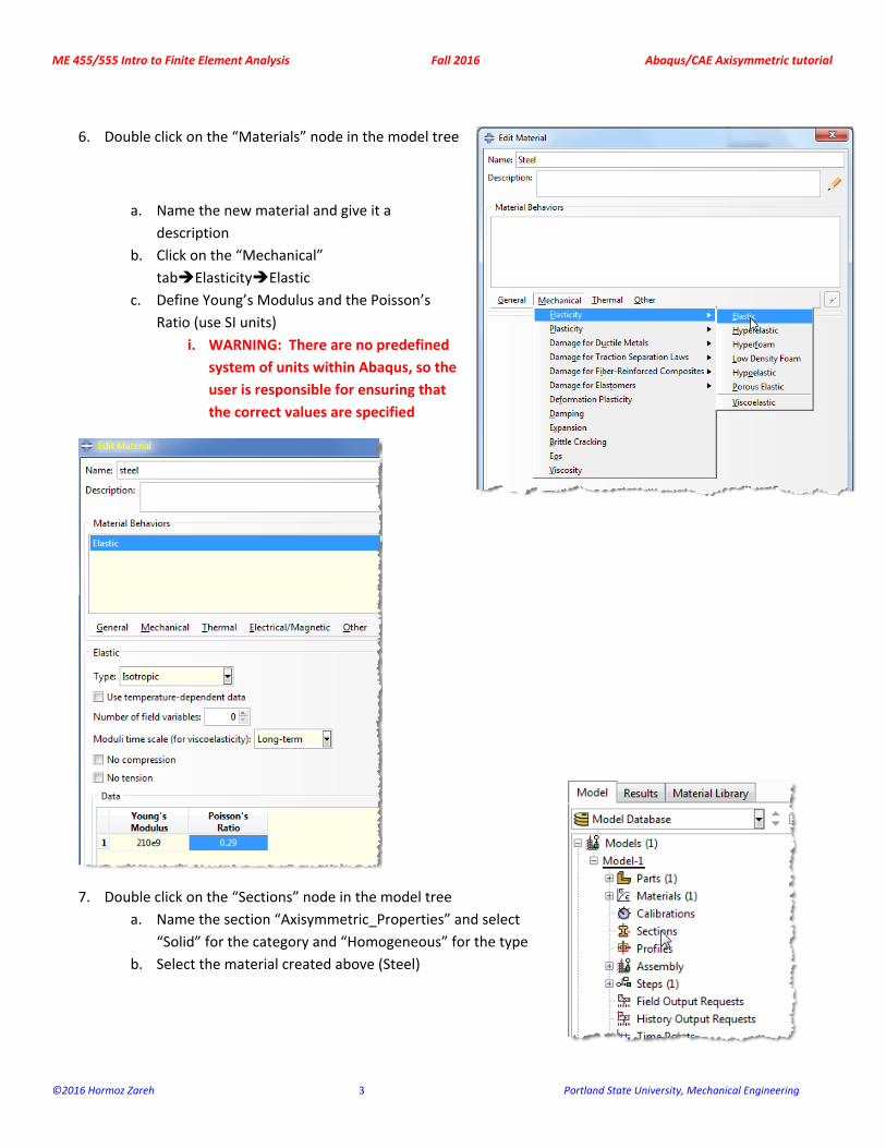
6. Double click on the “Materials” node in the model tree
a. Name the new material and give it a
description
b. Click on the “Mechanical”
tabElasticityElastic
c. Define Young’s Modulus and the Poisson’s
Ratio (use SI units)
i. WARNING: There are no predefined
system of units within Abaqus, so the
user is responsible for ensuring that
the correct values are specified
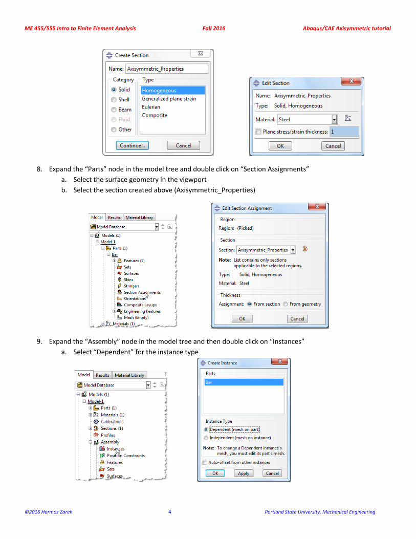
7. Double click on the “Sections” node in the model tree
a. Name the section “Axisymmetric_Properties” and select
“Solid” for the category and “Homogeneous” for the type
b. Select the material created above (Steel)
ME 455/555 Intro to Finite Element Analysis Fall 2016 Abaqus/CAE Axisymmetric tutorial
©2016 Hormoz Zareh 4 Portland State University, Mechanical Engineering
8. Expand the “Parts” node in the model tree and double click on “Section Assignments”
a. Select the surface geometry in the viewport
b. Select the section created above (Axisymmetric_Properties)
9. Expand the “Assembly” node in the model tree and then double click on “Instances”
a. Select “Dependent” for the instance type
ME 455/555 Intro to Finite Element Analysis Fall 2016 Abaqus/CAE Axisymmetric tutorial
©2016 Hormoz Zareh 5 Portland State University, Mechanical Engineering
10. Double click on the “Steps” node in the model tree
a. Name the step, set the procedure to “General”, and select “Static, General”
b. Give the step a description
11. Expand the Field Output Requests node in the model tree, and then double click on F‐Output‐1 (F‐Output‐1 was
automatically generated when creating the step)
a. Uncheck the variables “Strains” and “Contact”
12. Expand the History Output Requests node in the model tree, and then right click on H‐Output‐1 (H‐Output‐1 was
automatically generated when creating the step) and select Delete
ME 455/555 Intro to Finite Element Analysis Fall 2016 Abaqus/CAE Axisymmetric tutorial
©2016 Hormoz Zareh 6 Portland State University, Mechanical Engineering
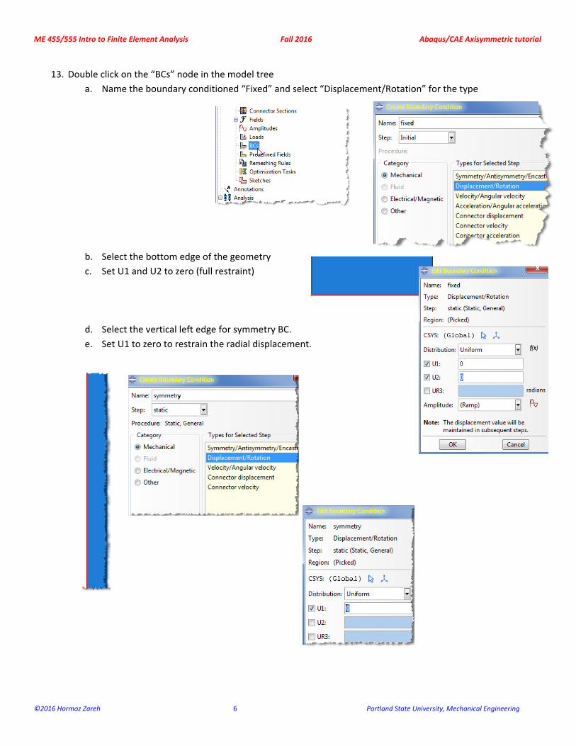
13. Double click on the “BCs” node in the model tree
a. Name the boundary conditioned “Fixed” and select “Displacement/Rotation” for the type
b. Select the bottom edge of the geometry
c. Set U1 and U2 to zero (full restraint)
d. Select the vertical left edge for symmetry BC.
e. Set U1 to zero to restrain the radial displacement.
ME 455/555 Intro to Finite Element Analysis Fall 2016 Abaqus/CAE Axisymmetric tutorial
©2016 Hormoz Zareh 7 Portland State University, Mechanical Engineering
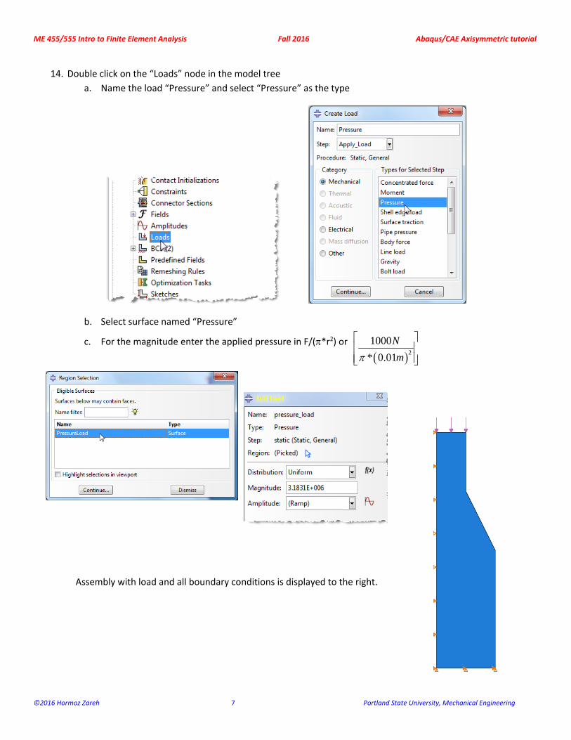
14. Double click on the “Loads” node in the model tree
a. Name the load “Pressure” and select “Pressure” as the type
b. Select surface named “Pressure”
c. For the magnitude enter the applied pressure in F/(*r2) or
2
1000
* 0.01
N
m
Assembly with load and all boundary conditions is displayed to the right.
ME 455/555 Intro to Finite Element Analysis Fall 2016 Abaqus/CAE Axisymmetric tutorial
©2016 Hormoz Zareh 8 Portland State University, Mechanical Engineering
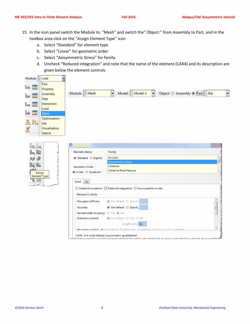
15. In the icon panel switch the Module to “Mesh” and switch the” Object:” from Assembly to Part, and in the
toolbox area click on the “Assign Element Type” icon
a. Select “Standard” for element type
b. Select “Linear” for geometric order
c. Select “Axisymmetric Stress” for family
d. Uncheck “Reduced integration” and note that the name of the element (CAX4) and its description are
given below the element controls
ME 455/555 Intro to Finite Element Analysis Fall 2016 Abaqus/CAE Axisymmetric tutorial
©2016 Hormoz Zareh 9 Portland State University, Mechanical Engineering
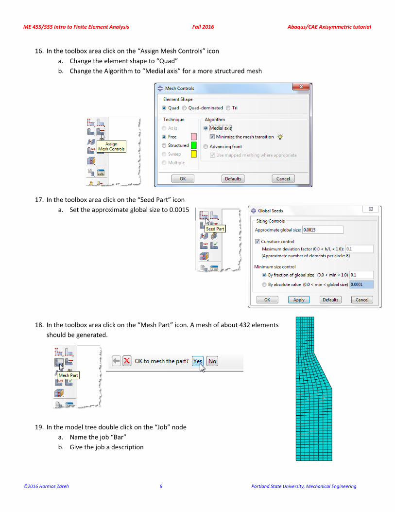
16. In the toolbox area click on the “Assign Mesh Controls” icon
a. Change the element shape to “Quad”
b. Change the Algorithm to “Medial axis” for a more structured mesh
17. In the toolbox area click on the “Seed Part” icon
a. Set the approximate global size to 0.0015
18. In the toolbox area click on the “Mesh Part” icon. A mesh of about 432 elements
should be generated.
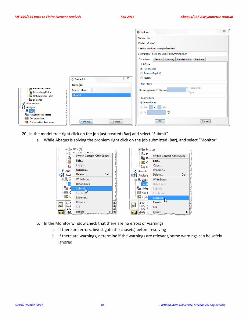
19. In the model tree double click on the “Job” node
a. Name the job “Bar”
b. Give the job a description
ME 455/555 Intro to Finite Element Analysis Fall 2016 Abaqus/CAE Axisymmetric tutorial
©2016 Hormoz Zareh 10 Portland State University, Mechanical Engineering
20. In the model tree right click on the job just created (Bar) and select “Submit”
a. While Abaqus is solving the problem right click on the job submitted (Bar), and select “Monitor”
b. In the Monitor window check that there are no errors or warnings
i. If there are errors, investigate the cause(s) before resolving
ii. If there are warnings, determine if the warnings are relevant, some warnings can be safely
ignored
ME 455/555 Intro to Finite Element Analysis Fall 2016 Abaqus/CAE Axisymmetric tutorial
©2016 Hormoz Zareh 11 Portland State University, Mechanical Engineering
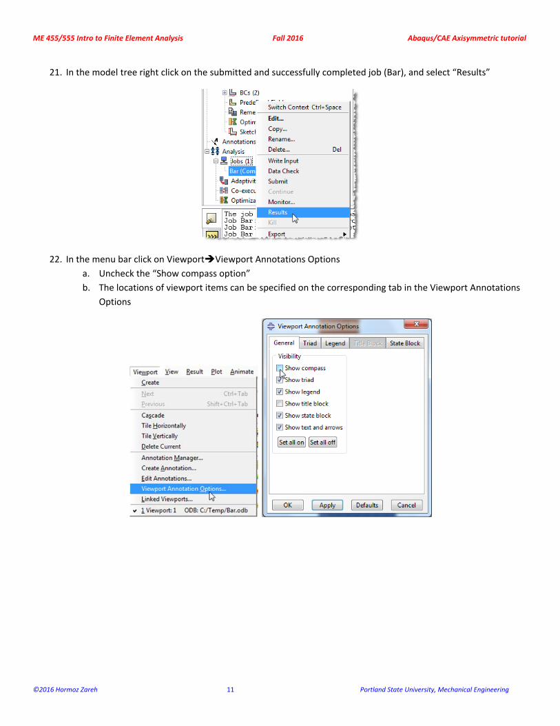
21. In the model tree right click on the submitted and successfully completed job (Bar), and select “Results”
22. In the menu bar click on ViewportViewport Annotations Options
a. Uncheck the “Show compass option”
b. The locations of viewport items can be specified on the corresponding tab in the Viewport Annotations
Options
ME 455/555 Intro to Finite Element Analysis Fall 2016 Abaqus/CAE Axisymmetric tutorial
©2016 Hormoz Zareh 12 Portland State University, Mechanical Engineering
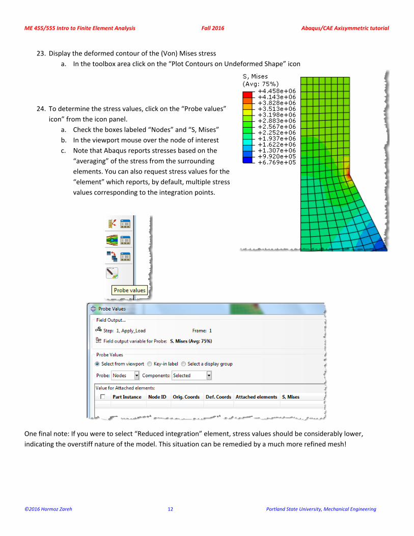
23. Display the deformed contour of the (Von) Mises stress
a. In the toolbox area click on the “Plot Contours on Undeformed Shape” icon
24. To determine the stress values, click on the “Probe values”
icon” from the icon panel.
a. Check the boxes labeled “Nodes” and “S, Mises”
b. In the viewport mouse over the node of interest
c. Note that Abaqus reports stresses based on the
“averaging” of the stress from the surrounding
elements. You can also request stress values for the
“element” which reports, by default, multiple stress
values corresponding to the integration points.
One final note: If you were to select “Reduced integration” element, stress values should be considerably lower,
indicating the overstiff nature of the model. This situation can be remedied by a much more refined mesh!