Pump and Fan Control (PFC) Application Program 5.x for ACS 600 Frequency Converters ACS 600 Firmware Manual This manual incudes information on: • Control Panel • Application macros • Parameters • Fault tracing • Fieldbus control • Example of PFC Application
Transcript
Pump and Fan Control (PFC)Application Program 5.x
for ACS 600 Frequency Converters
ACS 600 Firmware Manual
This manual incudes information on:• Control Panel• Application macros • Parameters• Fault tracing• Fieldbus control• Example of PFC Application
1998 ABB Industry Oy. All Rights Reserved.
Pump and Fan Control (PFC)Application Program 5.x
for ACS 600 Frequency Converters
Firmware Manual
3AFY 61279008 R0225EN
EFFECTIVE: 29.10.1998SUPERSEDES: 24.06.1997
ACS 600 Firmware Manual iii
Safety Instructions
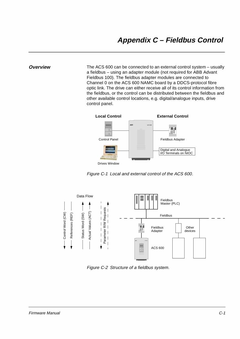
Overview This chapter states the safety instructions which must be followed when installing, operating and servicing the ACS 600. If neglected, physical injury and death may follow, or damage may occur to the frequency converter, the motor and driven equipment. The material in this chapter must be studied before attempting any work on, or with, the unit.
Warnings and Notes This manual distinguishes two sorts of safety instructions. Warnings are used to inform of conditions which can, if proper steps are not taken, lead to a serious fault condition, physical injury and death. Notes are used when the reader is required to pay special attention or when there is additional information available on the subject. Notes are less criticial than Warnings, but should not be disregarded.
Warnings Readers are informed of situations that can result in serious physical injury and/or serious damage to equipment with the following symbols:
Notes Readers are notified of the need for special attention or additional information available on the subject with the following symbols:
Dangerous Voltage Warning: warns of situations in which a high voltage can cause physical injury and/or damage equipment. The text next to this symbol describes ways to avoid the danger.
General Warning: warns of situations which can cause physical injury and/or damage equipment by means other than electrical. The text next to this symbol describes ways to avoid the danger.
Electrostatic Discharge Warning: warns of situations in which an electrostatic discharge can damage equipment. The text next to this symbol describes ways to avoid the danger.
CAUTION! Caution aims to draw special attention to a particular issue.
Note: Note gives additional information or points out more information available on the subject.
Safety Instructions
iv ACS 600 Firmware Manual
General SafetyInstructions
These safety instructions are intended for all work on the ACS 600. In addition to the instructions given below, there are more safety instructions on the first pages of the Installation and Start-up Manual.
WARNING! All electrical installation and maintenance work on the ACS 600 should be carried out by qualified electricians.
The ACS 600 and adjoining equipment must be properly earthed.
Do not attempt any work on a powered ACS 600. After switching off the mains, always allow the intermediate circuit capacitors 5 minutes to discharge before working on the frequency converter, the motor or the motor cable. It is good practice to check (with a voltage indicating instrument) that the frequency converter is in fact discharged before beginning work.
The ACS 600 motor cable terminals are at a dangerously high voltage when mains power is applied, regardless of motor operation.
There can be dangerous voltages inside the ACS 600 from external control circuits when the ACS 600 mains power is shut off. Exercise appropriate care when working with the unit. Neglecting these instructions can cause physical injury and death.
WARNING! The ACS 600 introduces electric motors, drive train mechanisms and driven machines to an extended operating range. It should be determined from the outset that all equipment is up to these conditions.
Operation is not allowed if the motor nominal voltage is less than one half of the ACS 600 nominal input voltage, or the motor nominal current is less than 1/6 of the ACS 600 nominal output current. Proper attention should be given to the motor insulation properties. The ACS 600 output comprises of short, high voltage pulses (approximately 1.35 ... 1.41 · mains voltage) regardless of output frequency. This voltage can be almost doubled by unfavourable motor cable properties. Contact an ABB office for additional information if multimotor operation is required. Neglecting these instructions can result in permanent damage to the motor.
All insulation tests must be carried out with the ACS 600 disconnected from the cabling. Operation outside the rated capacities should not be attempted. Neglecting these instructions can result in permanent damage to the ACS 600.
There are several automatic reset functions in the ACS 600. If selected, they reset the unit and resume operation after a fault. These functions should not be selected if other equipment is not compatible with this kind of operation, or dangerous situations can be caused by such action.
Overview This chapter describes the purpose, contents and the intended audience of this manual. It also lists related publications.
This Manual is compatible with the Pump and Fan Application Program version 5.0 or later.
Before You Start The purpose of this manual is to provide you with the information necessary to control and program your ACS 600 drive.
The audience for this manual is expected to have:
• Knowledge of standard electrical wiring practices, electronic components, and electrical schematic symbols.
• Minimal knowledge of ABB product names and terminology.
• No experience or training in installing, operating, or servicing the ACS 600.
What This Manual Contains
Safety Instructions can be found on pages iii - iv of this manual. The Safety Instructions describe the formats for various warnings and notations used in this manual. This chapter also states the general safety instructions which must be followed.
Chapter 1 – Introduction to This Manual, the chapter you are reading now, introduces you to the ACS 600 Firmware Manual.
Chapter 2 – Overview of ACS 600 Programming and the CDP 312 Control Panel provides an overview of programming your ACS 600. This chapter describes the operation of the Control Panel used for controlling and programming.
Chapter 3 – Start-up Data lists and explains the Start-up Data parameters and describes the ID Run procedure.
Chapter 4 – Control Operation describes actual signals and keypad and external controls.
Chapter 5 – Application Macros describes the operation of the PFC Macro, the Hand/Auto Macro and the User Macro.
Chapter 6 – Parameters lists the ACS 600 parameters and explains the functions of each parameter.
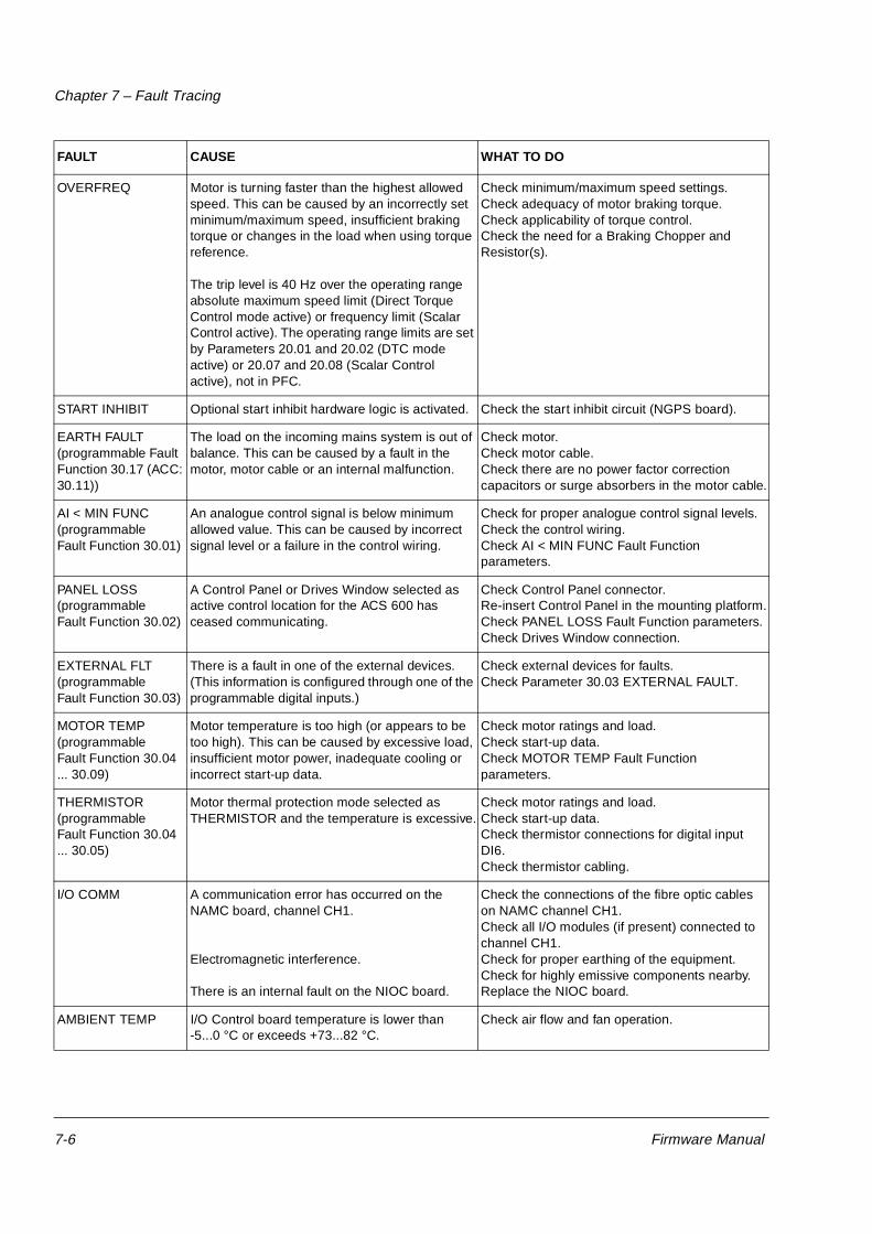
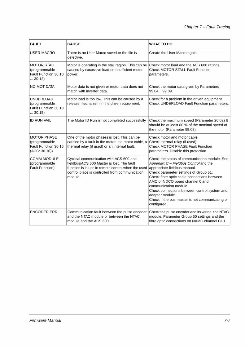
Chapter 7 – Fault Tracing lists the ACS 600 fault and warning messages, possible causes and remedies.
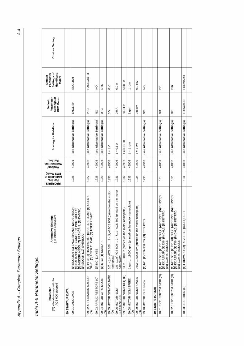
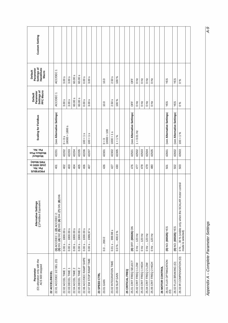
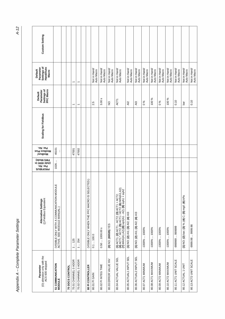
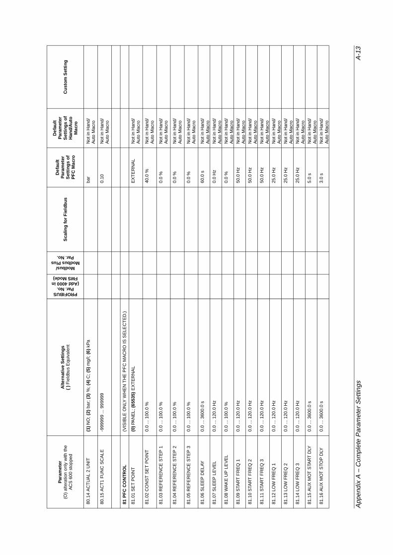
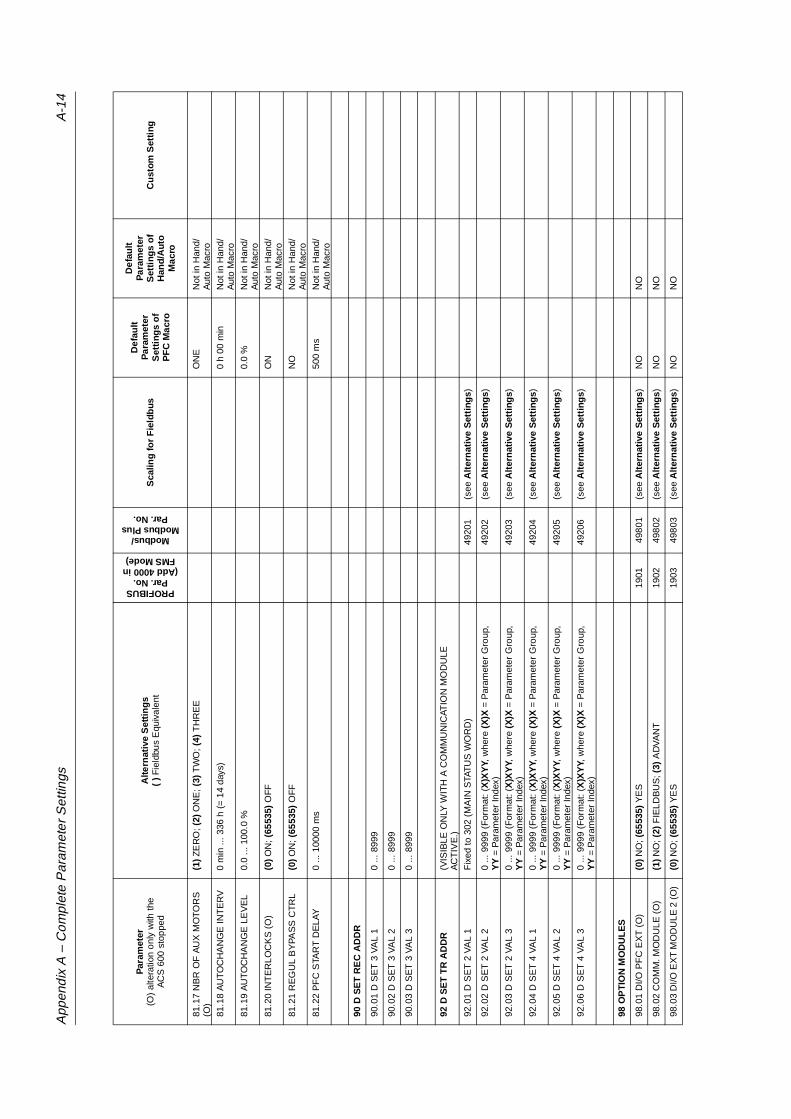
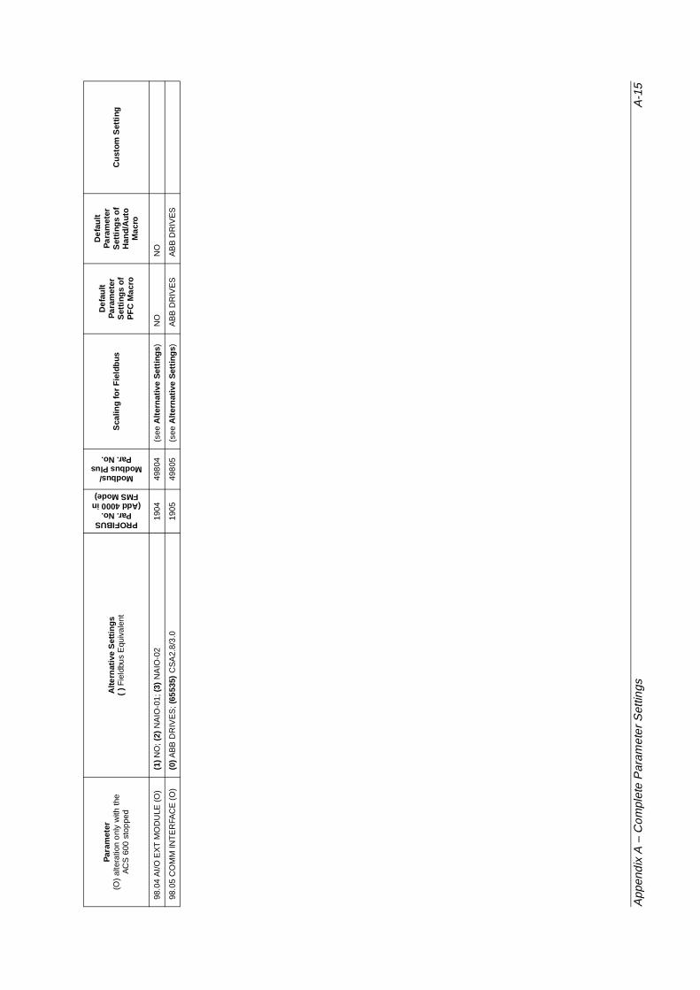
Appendix A – Complete Parameter Settings lists, in tabular form, all parameter settings for the ACS 600 with PFC application Program.
Appendix B – Example of PFC Application presents briefly an existing
Chapter 1 – Introduction to This Manual
1-2 Firmware Manual
two-pump PFC application.
Appendix C – Fieldbus Control contains the information needed to control the ACS 600 through a fieldbus adapter module. There are several fieldbus adapter modules for the ACS 600 available as optional equipment.
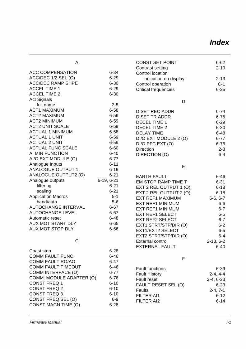
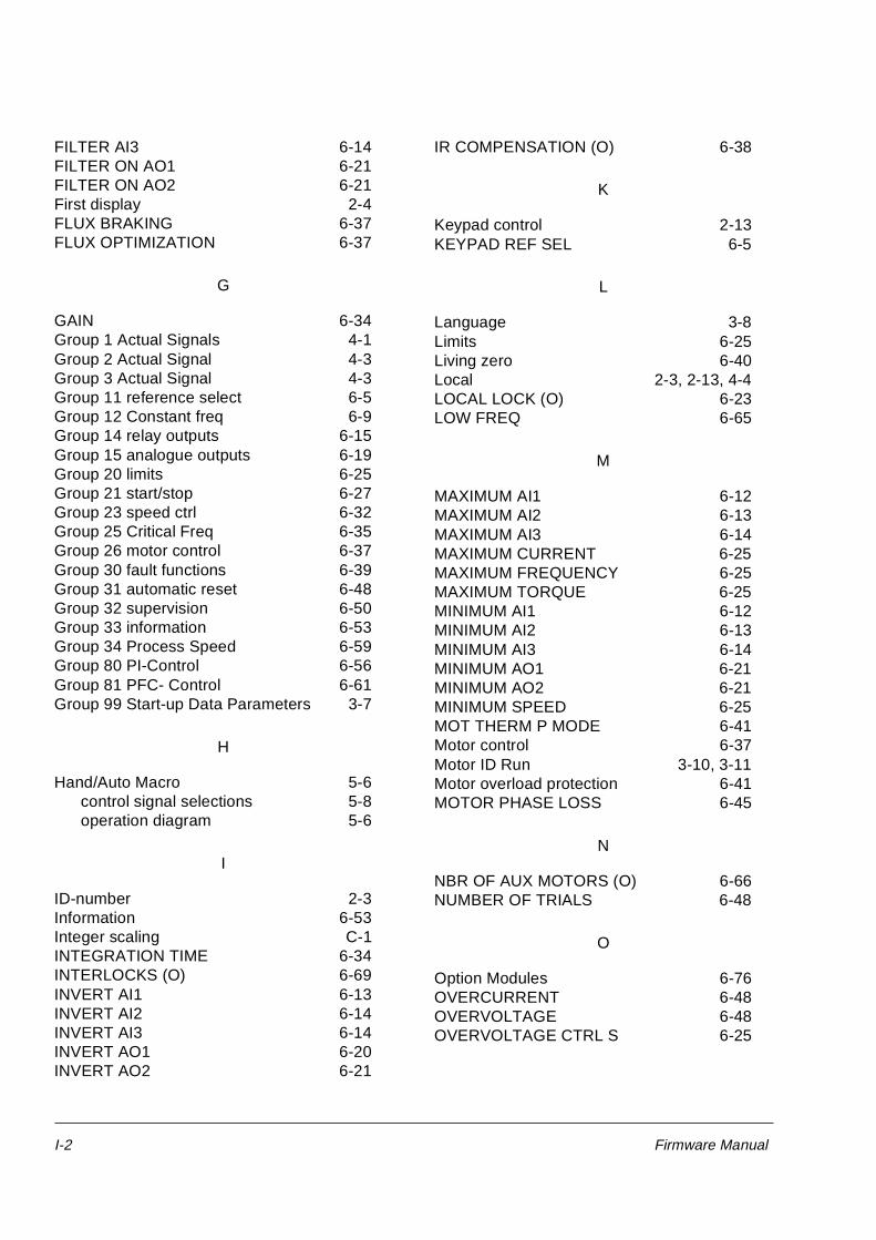
Index helps you locate the page numbers of topics contained in this manual.
Related Publications In addition to this manual the ACS 600 user documentation includes the following manuals:
• Hardware manuals/installation manuals
• Several Installation and Start-up Guides for the optional devices for the ACS 600
Firmware Manual 2-1
Chapter 2 – Overview of ACS 600 Programming andthe CDP 312 Control Panel
Overview This chapter describes how to use the panel with ACS 600 to modify parameters, monitor actual values and control the drive.
Note: The CDP 312 Panel does not communicate with ACS 600 application program versions 3.x or earlier. The CDP 311 Panel does not communicate with program version 5.x or later.
ACS 600 Programming The user can change the configuration of the ACS 600 to meet the needs of the application by programming. The ACS 600 is programmable through a set of parameters.
Application Macros Parameters can be set one by one or a preprogrammed set of parameters can be selected. Preprogrammed parameter sets are called Application Macros. See Chapter 5 – Application Macros for further information on the Application Macros.
Parameter Groups In order to simplify programming, parameters in the ACS 600 are organised in Groups. Parameters of the Start-Up Data Group are described in Chapter 3 – Start-up Data and other parameters in Chapter 6 – Parameters.
Start-up Data Parameters The Start-up Data Group contains the basic settings needed to match the ACS 600 with your motor and to set the Control Panel display language. This group also contains a list of preprogrammed Application Macros. The Start-up Data Group includes parameters that are set at start-up, and should not need to be changed later on. See Chapter 3 – Start-up Data for description of each parameter.
Control Panel The Control Panel is the device used for controlling and programming the ACS 600. The Panel can be attached directly to the door of the cabinet or it can be mounted, for example, in a control desk.
Chapter 2 – Overview of ACS 600 Programming and the CDP 312 Control Panel
2-2 Firmware Manual
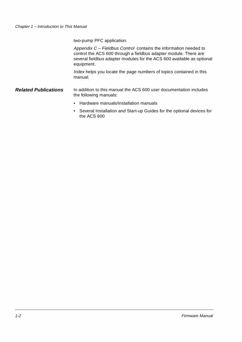
Figure 2-1 The Control Panel.
Display The LCD type display has 4 lines of 20 characters.
The language selection is made at start-up with Parameter 99.01 LANGUAGE. Depending on customer selection, a set of four languages is loaded into the memory of the ACS 600 at the factory (see Chapter 3 – Start-up Data).
Keys The keys on the Control Panel are flat, labelled push-buttons. Their functions are explained on the next page.
1 L " 45.00 Hz I10 START/STOP01 EXT1 STRT/STP/DIR DI1
1 L " 45.00 Hz IUPLOAD <=<=DOWNLOAD =>=>CONTRAST 7
ACS 601 75 kW
ASAA5000 xxxxxxID NUMBER 1
Status Row
SelectableFunctions
Application SW Name and Version Date
Act. Signal/Fault Message scrolling
R = External
LOC
RESET
REF
REM Keypad / External Control
Fault Reset
Reference Setting Function
Forward
Reverse
Start
Stop
I
0
Chapter 2 – Overview of ACS 600 Programming and the CDP 312 Control Panel
2-4 Firmware Manual
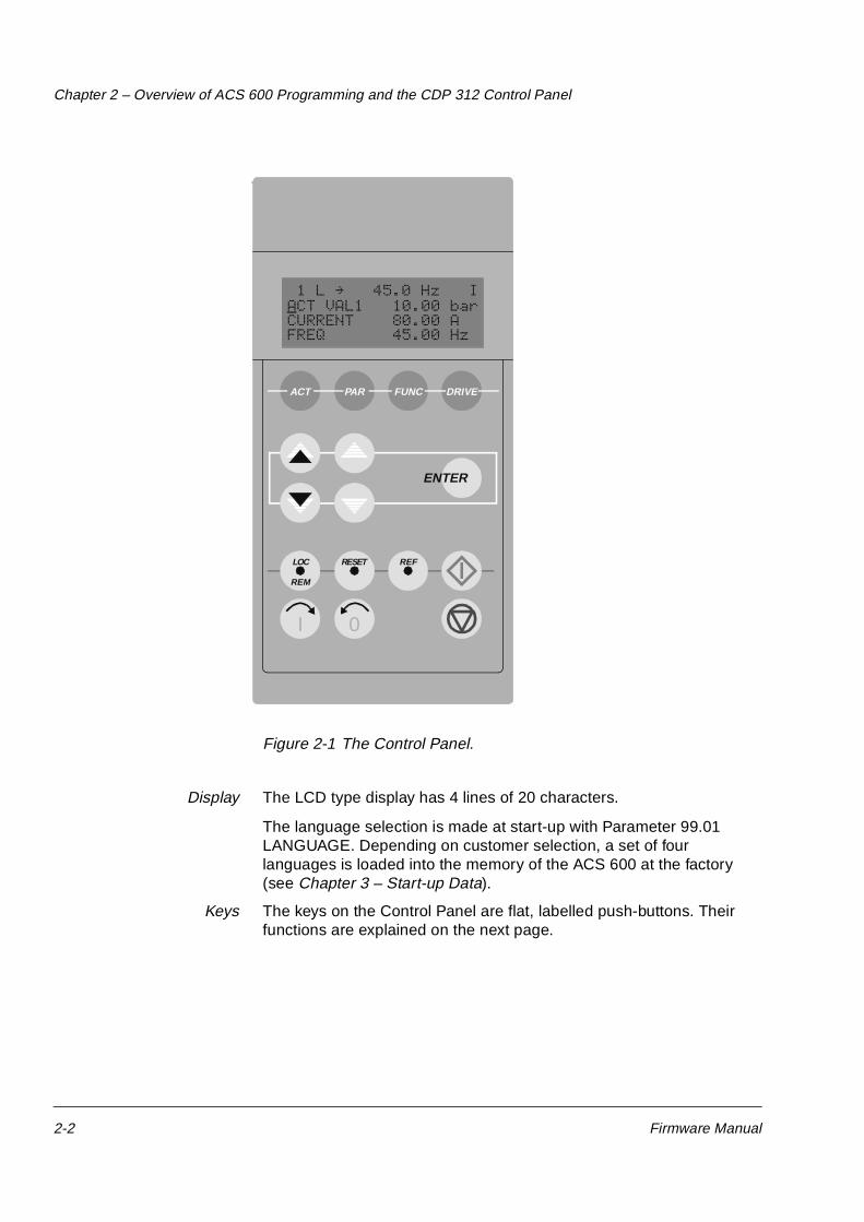
Panel Operation The following is a description of the operation of the Control Panel. The Control Panel Keys and Displays are explained in Figure 2-1, Figure 2-2, and Figure 2-3.
Keypad Modes The Control Panel has four different keypad modes: Actual Signal Display Mode, Parameter Mode, Function Mode, and Drive Selection Mode. In addition to these, there is a special Identification Display, which is displayed after connecting the panel to the link. The Identification Display and the keypad modes are described briefly below.
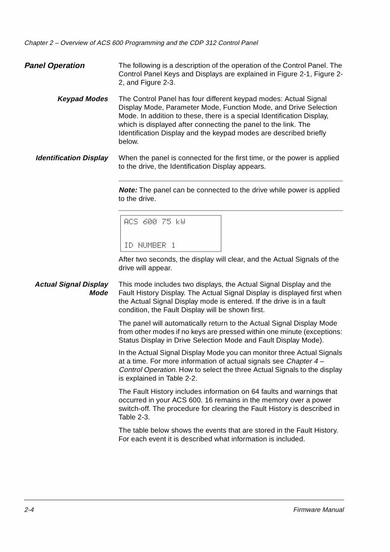
Identification Display When the panel is connected for the first time, or the power is applied to the drive, the Identification Display appears.
Note: The panel can be connected to the drive while power is applied to the drive.
After two seconds, the display will clear, and the Actual Signals of the drive will appear.
Actual Signal DisplayMode
This mode includes two displays, the Actual Signal Display and the Fault History Display. The Actual Signal Display is displayed first when the Actual Signal Display mode is entered. If the drive is in a fault condition, the Fault Display will be shown first.
The panel will automatically return to the Actual Signal Display Mode from other modes if no keys are pressed within one minute (exceptions: Status Display in Drive Selection Mode and Fault Display Mode).
In the Actual Signal Display Mode you can monitor three Actual Signals at a time. For more information of actual signals see Chapter 4 – Control Operation. How to select the three Actual Signals to the display is explained in Table 2-2.
The Fault History includes information on 64 faults and warnings that occurred in your ACS 600. 16 remains in the memory over a power switch-off. The procedure for clearing the Fault History is described in Table 2-3.
The table below shows the events that are stored in the Fault History. For each event it is described what information is included.
ACS 600 75 kW
ID NUMBER 1
Chapter 2 – Overview of ACS 600 Programming and the CDP 312 Control Panel
Firmware Manual 2-5
When a fault or warning occurs in the drive, the message will be displayed immediately, except in the Drive Selection Mode. Table 2-4 shows how to reset a fault. From the fault display, it is possible to change to other displays without resetting the fault. If no keys are pressed the fault or warning text is displayed as long as the fault exists.
See Chapter 7 – Fault Tracing for information on fault tracing.
Table 2-1 How to display the full name of the three Actual Signals.
Step Function Press key Display
1. To display the full name of the three actual signals.
Hold
2. To return to the Actual Signal Display Mode.
Release
1 L " 45.0 Hz I2 LAST FAULT+OVERVOLTAGE 1121 H 1 MIN 23 S
Event Information
A fault is detected by ACS 600. Sequential number of the event.Name of the fault and a “+” sign in front of the name.Total power on time.
A fault is reset by user. Sequential number of the event.-RESET FAULT text.Total power on time.
A warning is activated by ACS 600.
Sequential number of the event.Name of the warning and a “+” sign in front of the name.Total power on time.
A warning is deactivated by ACS 600.
Sequential number of the event.Name of the warning and a “-” sign in front of the name.Total power on time.
Chapter 2 – Overview of ACS 600 Programming and the CDP 312 Control Panel
2-8 Firmware Manual
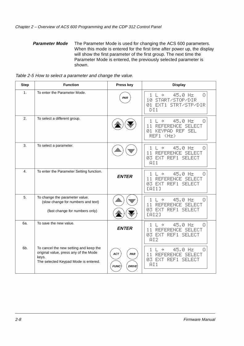
Parameter Mode The Parameter Mode is used for changing the ACS 600 parameters. When this mode is entered for the first time after power up, the display will show the first parameter of the first group. The next time the Parameter Mode is entered, the previously selected parameter is shown.
Table 2-5 How to select a parameter and change the value.
Step Function Press key Display
1. To enter the Parameter Mode.
2. To select a different group.
3. To select a parameter.
4. To enter the Parameter Setting function.
5. To change the parameter value. (slow change for numbers and text)
(fast change for numbers only)
6a. To save the new value.
6b. To cancel the new setting and keep the original value, press any of the Mode keys.The selected Keypad Mode is entered.
PAR 1 L " 45.0 Hz O10 START/STOP/DIR01 EXT1 STRT/STP/DIR DI1
1 L " 45.0 Hz O11 REFERENCE SELECT01 KEYPAD REF SEL REF1 (Hz)
ENTER 1 L " 45.0 Hz O11 REFERENCE SELECT03 EXT REF1 SELECT AI2
ACT
FUNC DRIVE
PAR 1 L " 45.0 Hz O11 REFERENCE SELECT03 EXT REF1 SELECT AI1
Chapter 2 – Overview of ACS 600 Programming and the CDP 312 Control Panel
Firmware Manual 2-9
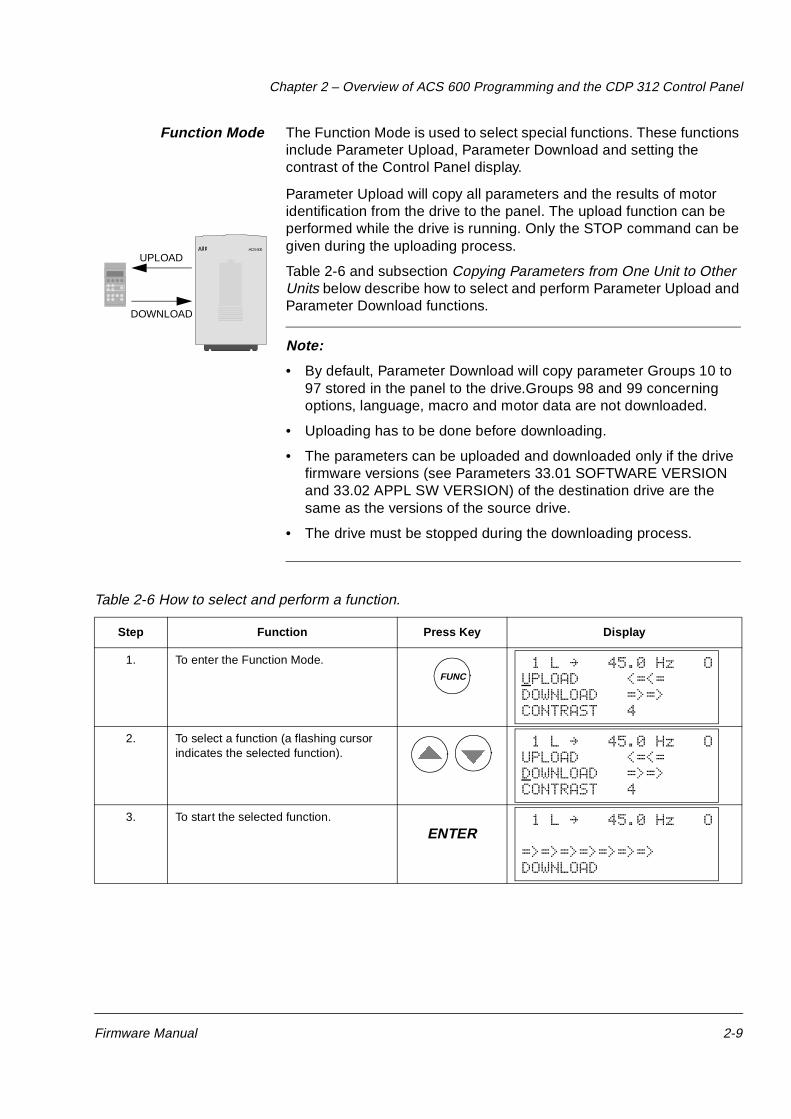
Function Mode The Function Mode is used to select special functions. These functions include Parameter Upload, Parameter Download and setting the contrast of the Control Panel display.
Parameter Upload will copy all parameters and the results of motor identification from the drive to the panel. The upload function can be performed while the drive is running. Only the STOP command can be given during the uploading process.
Table 2-6 and subsection Copying Parameters from One Unit to Other Units below describe how to select and perform Parameter Upload and Parameter Download functions.
Note:
• By default, Parameter Download will copy parameter Groups 10 to 97 stored in the panel to the drive.Groups 98 and 99 concerning options, language, macro and motor data are not downloaded.
• Uploading has to be done before downloading.
• The parameters can be uploaded and downloaded only if the drive firmware versions (see Parameters 33.01 SOFTWARE VERSION and 33.02 APPL SW VERSION) of the destination drive are the same as the versions of the source drive.
• The drive must be stopped during the downloading process.
Table 2-6 How to select and perform a function.
Step Function Press Key Display
1. To enter the Function Mode.
2. To select a function (a flashing cursor indicates the selected function).
3. To start the selected function.
ACS 600
UPLOAD
DOWNLOAD
FUNC 1 L " 45.0 Hz OUPLOAD <=<=DOWNLOAD =>=>CONTRAST 4
1 L " 45.0 Hz OUPLOAD <=<=DOWNLOAD =>=>CONTRAST 4
ENTER 1 L " 45.0 Hz O
=>=>=>=>=>=>=>DOWNLOAD
Chapter 2 – Overview of ACS 600 Programming and the CDP 312 Control Panel
2-10 Firmware Manual
Table 2-7 How to set the contrast of the panel display.
Step Function Press Key Display
1. To enter the Function Mode.
2. To select a function (a flashing cursor indicates the selected function).
3. To enter the contrast setting function.
4. To adjust the contrast.
5.a To accept the selected value.
5.b To cancel the new setting and retain the original value, press any of the Mode keys.
The selected Keypad Mode is entered.
FUNC 1 L " 45.0 Hz OUPLOAD <=<=DOWNLOAD =>=>CONTRAST 4
1 L " 45.0 Hz OUPLOAD <=<=DOWNLOAD =>=>CONTRAST 4
ENTER 1 L " 45.0 Hz OCONTRAST [4]
1 L " 45.0 Hz OCONTRAST [6]
ENTER 1 L " 45.0 Hz OUPLOAD <=<=DOWNLOAD =>=>CONTRAST 6
ACT
FUNC DRIVE
PAR 1 L " 45.0 Hz OUPLOAD <=<=DOWNLOAD =>=>CONTRAST 4
Chapter 2 – Overview of ACS 600 Programming and the CDP 312 Control Panel
Firmware Manual 2-11
Copying Parameters fromOne Unit to Other Units
You can copy parameters from one drive to another by using the Parameter Upload and Parameter Download functions in the Function Mode. Follow the procedure below:
1. Select the correct options (Group 98), language and macro (Group 99) for each drive.
2. Set the rating plate values for the motors (Group 99), and perform the identification for each motor (the Identification Magnetisation at zero speed by pressing start, or an ID Run. For the ID Run procedure see Chapter 3 – Start-up Data).
3. Set the parameters in Groups 10 to 97 as preferred in one ACS 600 drive.
4. Upload the parameters from the ACS 600 to the panel (see Table 2-6).
5. Press the key to change to external control (no L visible on the first row of the display).
6. Disconnect the panel and reconnect it to the next ACS 600 unit.
7. Ensure the target ACS 600 is in Local control (L shown on the first row of the display). If necessary, change by pressing .
8. Download the parameters from the panel to the ACS 600 unit (see Table 2-6).
9. Repeat steps 7. and 8. for the rest of the units.
Note: Parameters in Groups 98 and 99 concerning options, language, macro and motor data are not downloaded.1)
LOC
REM
LOC
REM
1) The restriction prevents downloading of incorrect motor data (Group 99). In special cases it is also possible to download Groups 98 and 99 and the results of the motor identification. For more informa-tion, please contact your local ABB representative.
Chapter 2 – Overview of ACS 600 Programming and the CDP 312 Control Panel
2-12 Firmware Manual
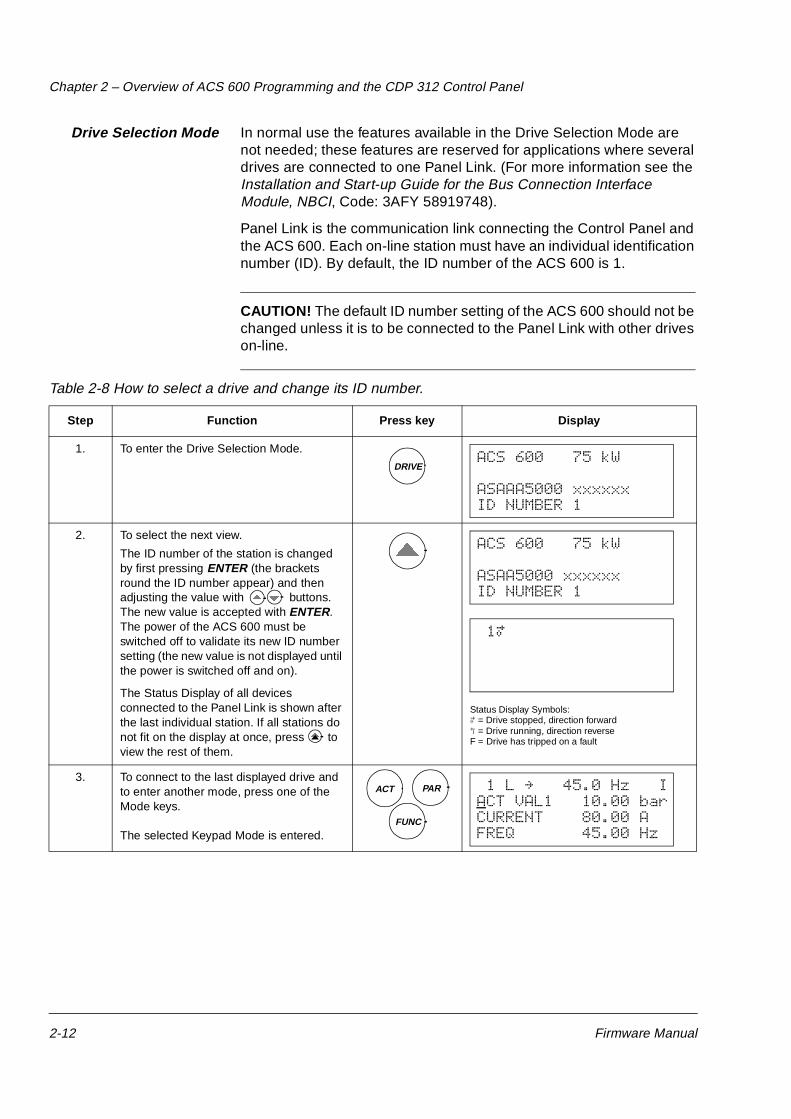
Drive Selection Mode In normal use the features available in the Drive Selection Mode are not needed; these features are reserved for applications where several drives are connected to one Panel Link. (For more information see the Installation and Start-up Guide for the Bus Connection Interface Module, NBCI, Code: 3AFY 58919748).
Panel Link is the communication link connecting the Control Panel and the ACS 600. Each on-line station must have an individual identification number (ID). By default, the ID number of the ACS 600 is 1.
CAUTION! The default ID number setting of the ACS 600 should not be changed unless it is to be connected to the Panel Link with other drives on-line.
Table 2-8 How to select a drive and change its ID number.
Step Function Press key Display
1. To enter the Drive Selection Mode.
2. To select the next view.
The ID number of the station is changed by first pressing ENTER (the brackets round the ID number appear) and then adjusting the value with buttons. The new value is accepted with ENTER. The power of the ACS 600 must be switched off to validate its new ID number setting (the new value is not displayed until the power is switched off and on).
The Status Display of all devices connected to the Panel Link is shown after the last individual station. If all stations do not fit on the display at once, press to view the rest of them.
Status Display Symbols:á = Drive stopped, direction forwardÑ = Drive running, direction reverseF = Drive has tripped on a fault
3. To connect to the last displayed drive and to enter another mode, press one of the Mode keys.
The selected Keypad Mode is entered.
DRIVEACS 600 75 kW
ASAAA5000 xxxxxxID NUMBER 1
ACS 600 75 kW
ASAA5000 xxxxxxID NUMBER 1
1á
PAR
FUNC
ACT 1 L " 45.0 Hz IACT VAL1 10.00 bar CURRENT 80.00 AFREQ 45.00 Hz
Chapter 2 – Overview of ACS 600 Programming and the CDP 312 Control Panel
Firmware Manual 2-13
Operational Commands Operational commands control the operation of the ACS 600. They include starting and stopping the drive, changing the direction of rotation and adjusting the reference. The reference value is used for controlling motor frequency or process value.
Changing ControlLocation
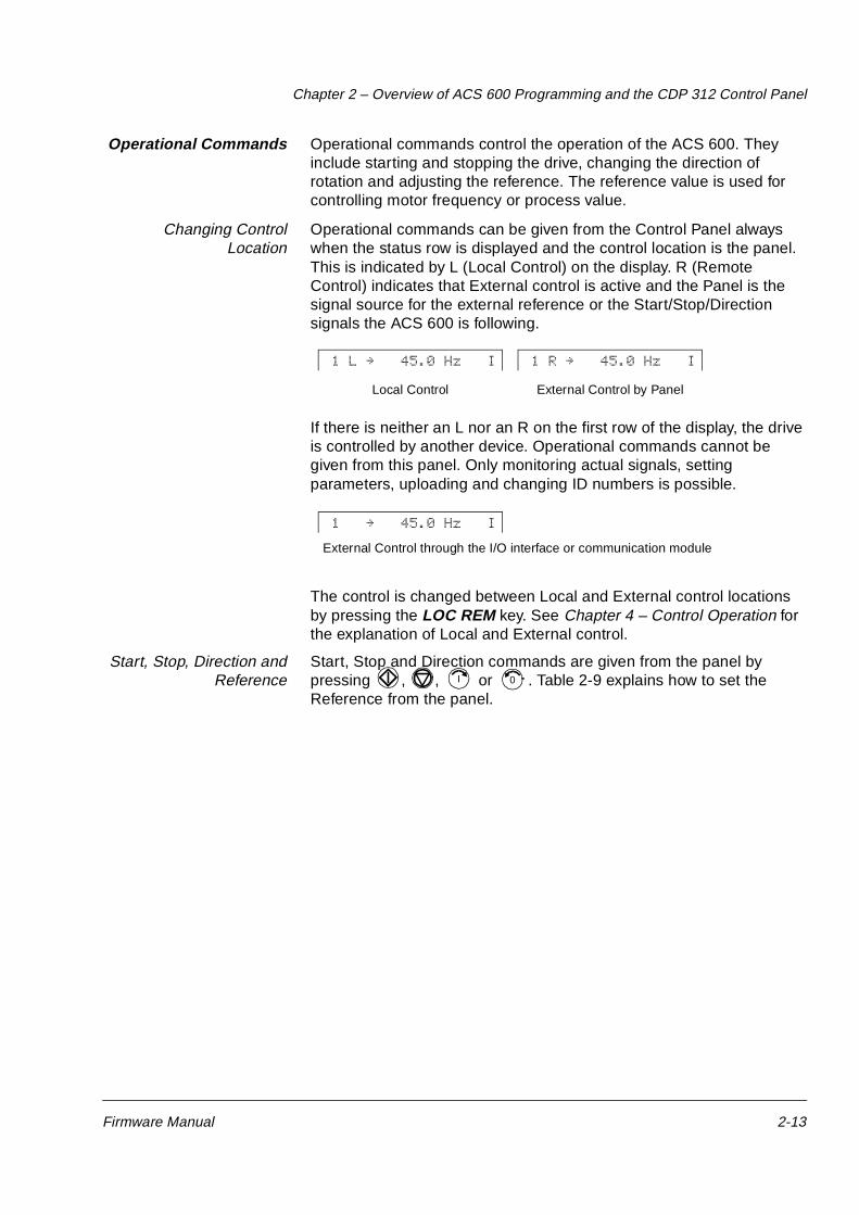
Operational commands can be given from the Control Panel always when the status row is displayed and the control location is the panel. This is indicated by L (Local Control) on the display. R (Remote Control) indicates that External control is active and the Panel is the signal source for the external reference or the Start/Stop/Direction signals the ACS 600 is following.
If there is neither an L nor an R on the first row of the display, the drive is controlled by another device. Operational commands cannot be given from this panel. Only monitoring actual signals, setting parameters, uploading and changing ID numbers is possible.
The control is changed between Local and External control locations by pressing the LOC REM key. See Chapter 4 – Control Operation for the explanation of Local and External control.
Start, Stop, Direction andReference
Start, Stop and Direction commands are given from the panel by pressing , , or . Table 2-9 explains how to set the Reference from the panel.
1 L " 45.0 Hz I 1 R " 45.0 Hz I
Local Control External Control by Panel
1 " 45.0 Hz I
External Control through the I/O interface or communication module
I 0
Chapter 2 – Overview of ACS 600 Programming and the CDP 312 Control Panel
2-14 Firmware Manual
Table 2-9 How to set the reference.
Step Function Press Key Display
1. To enter a Keypad Mode displaying the status row, press a Mode key.
2. To enter the Reference Setting function. A blinking cursor indicates that the Reference Setting function has been selected.
3. To change the reference.(slow change)
(fast change)
4.a To save the reference press Enter.The value is stored in the permanent memory. It is restored automatically after power switch-off.
4.b To escape the Reference Setting Mode,without saving the value in the permanent memory, press any of the Mode keys.The selected Keypad Mode is entered.
ACT PAR
FUNC
1 L " 45.0 Hz IACT VAL1 10.00 bar CURRENT 80.00 AFREQ 45.00 Hz
REF 1 L " [ 45.0 Hz ] IACT VAL1 10.00 bar CURRENT 80.00 AFREQ 45.00 Hz
1 L " [ 48.0 Hz ] IACT VAL1 10.00 bar CURRENT 81.00 AFREQ 48.00 Hz
ENTER 1 L " 48.0 Hz IACT VAL1 10.00 bar CURRENT 81.00 AFREQ 48.00 Hz
ACT PAR
FUNC DRIVE
1 L " 48.0 Hz IACT VAL1 10.00 bar CURRENT 81.00 AFREQ 48.00 Hz
Firmware Manual 3-1
Chapter 3 – Start-up Data
Overview The first part of this chapter is the Start-up Procedure of ACS 600 frequency converters.
The second part of the chapter lists and explains the Start-up Data Parameters. The Start-up Data Parameters are a special set of parameters that allow you to set up the ACS 600 and motor information. Start-up Data Parameters should only need to be set during start-up and should not need to be changed afterwards.
Start-up Procedure Table below is a step-by-step instruction to initialise the ACS 600 frequency converter into use. The procedure is common for several ACS 600 Programs, the Pump and Fan Control (PFC) Program among the others. Since the procedure is generic and based on the Standard Application Program, display views of the Control Panel does not completely match the views of the PFC Program.
Note: Before beginning the start-up of ACS 600 equipped with Pump and Fan Control (PFC) Program, ensure that all the interlock inputs are ON at the digital I/O terminal of the standard I/O Board, NIOC.
START-UP PROCEDURE
1 – SAFETY
The start-up procedure must only be carried out by a qualified electrician.
The safety instructions must be followed during the start-up procedure. See the appropriate hardware manual for the safety instructions.
The ACx 600 must not be powered up more than five times in ten minutes to avoid charging resistor overheating (no limitation for ACS 600 MultiDrive and ACx 607 units -0760-3, -0930-5, -0900-6 or above).
Check the installation before the start-up procedure. See the installation checklist from the appropriate hardware/installation manual.
Check that starting the motor does not cause any danger.
It is recommended having the driven equipment disengaged when first start is performed if there is the risk of damage to the driven equipment in case of incorrect rotation direction of the motor.
Chapter 3 – Start-up Data
3-2 Firmware Manual
2 – POWER-UP
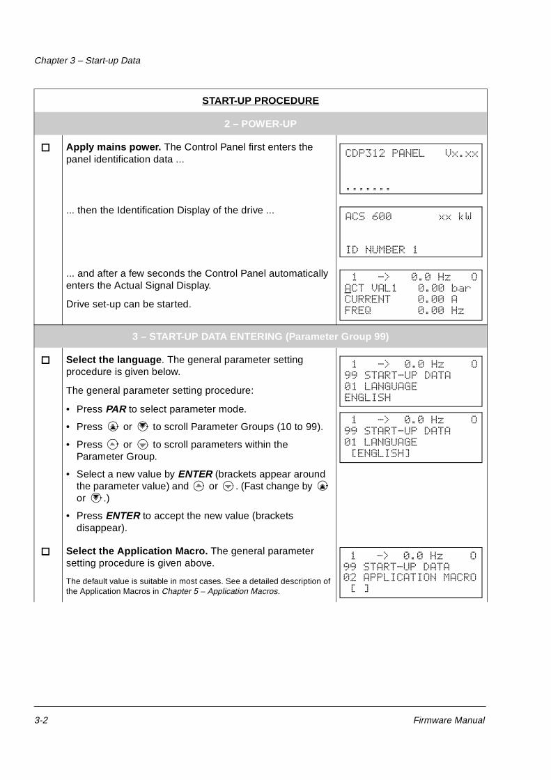
Apply mains power. The Control Panel first enters the panel identification data ...
... then the Identification Display of the drive ...
... and after a few seconds the Control Panel automatically enters the Actual Signal Display.
Drive set-up can be started.
3 – START-UP DATA ENTERING (Parameter Group 99)
Select the language . The general parameter setting procedure is given below.
The general parameter setting procedure:
• Press PAR to select parameter mode.
• Press or to scroll Parameter Groups (10 to 99).
• Press or to scroll parameters within the Parameter Group.
• Select a new value by ENTER (brackets appear around the parameter value) and or . (Fast change by or .)
• Press ENTER to accept the new value (brackets disappear).
Select the Application Macro. The general parameter setting procedure is given above.
The default value is suitable in most cases. See a detailed description of the Application Macros in Chapter 5 – Application Macros.
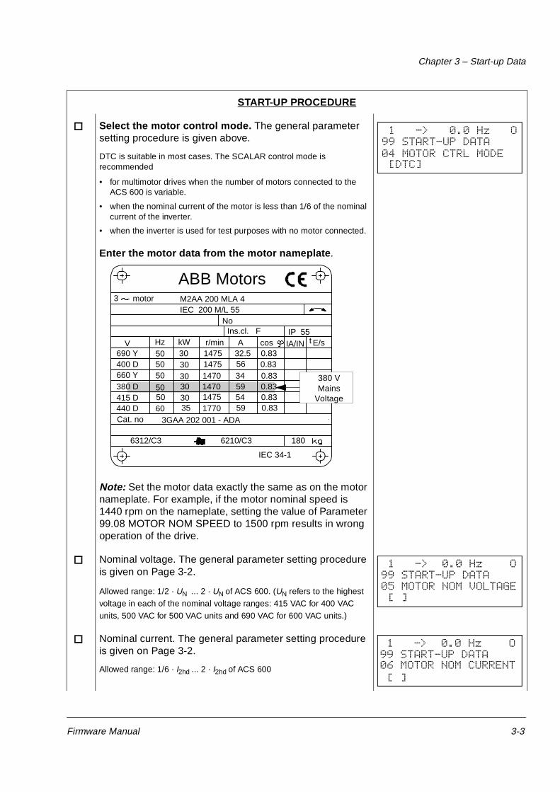
Select the motor control mode. The general parameter setting procedure is given above.
DTC is suitable in most cases. The SCALAR control mode is recommended
• for multimotor drives when the number of motors connected to the ACS 600 is variable.
• when the nominal current of the motor is less than 1/6 of the nominal current of the inverter.
• when the inverter is used for test purposes with no motor connected.
Enter the motor data from the motor nameplate.
Note: Set the motor data exactly the same as on the motor nameplate. For example, if the motor nominal speed is 1440 rpm on the nameplate, setting the value of Parameter 99.08 MOTOR NOM SPEED to 1500 rpm results in wrong operation of the drive.
Nominal voltage. The general parameter setting procedure is given on Page 3-2.
Allowed range: 1/2 · UN ... 2 · UN of ACS 600. (UN refers to the highest
voltage in each of the nominal voltage ranges: 415 VAC for 400 VAC
units, 500 VAC for 500 VAC units and 690 VAC for 600 VAC units.)
Nominal current. The general parameter setting procedure is given on Page 3-2.
Allowed range: 1/6 · I2hd ... 2 · I2hd of ACS 600
START-UP PROCEDURE
1 -> 0.0 Hz O99 START-UP DATA 04 MOTOR CTRL MODE [DTC]
M2AA 200 MLA 4
147514751470147014751770
32.55634595459
0.830.830.830.830.830.83
3GAA 202 001 - ADA
180
IEC 34-1
6210/C36312/C3
Cat. no 35 30 30 30 30 3050
5050
505060
690 Y400 D660 Y380 D415 D440 D
V Hz kW r/min A cos IA/IN t E/sIns.cl. F IP 55
NoIEC 200 M/L 55
3 motor
ABB Motors
380 VMains
Voltage
1 -> 0.0 Hz O99 START-UP DATA 05 MOTOR NOM VOLTAGE [ ]
1 -> 0.0 Hz O99 START-UP DATA 06 MOTOR NOM CURRENT [ ]
Chapter 3 – Start-up Data
3-4 Firmware Manual
Nominal frequency. The general parameter setting procedure is given on Page 3-2.
Range: 8 ... 300 Hz
Nominal speed. The general parameter setting procedure is given on Page 3-2.
Range: 1 ... 18000 rpm
Nominal power. The general parameter setting procedure is given on Page 3-2.
Range: 0... 9000 kW
When the motor data has been entered a warning appears. It indicates that the motor parameters have been set, and the ACS 600 is ready to start the motor identification (ID magnetisation or ID Run).
Select the motor identification. The general parameter setting procedure is given on Page 3-2.
The default value NO is suitable for most applications. It is applied in this basic start-up procedure.
The ID Run (STANDARD or REDUCED) should be selected instead if:
• Operation point is near zero speed.
• Operation at torque range above the motor nominal torque within wide speed range and without any pulse encoder (i.e. without any measured speed feedback) is required.
See the second part of this chapter for the ID Run procedure.
4 – IDENTIFICATION MAGNETISATIONwith Motor ID Run selection NO
Press the LOC/REM key to change to local control (L shown on the first row).
Press the to start the magnetisation. The motor is magnetised at zero speed for 20 to 60 s. Two warnings are displayed:
• The upper warning is displayed while the magnetisation is on.
• The lower warning is displayed after the magnetisation is completed.
START-UP PROCEDURE
1 -> 0.0 Hz O99 START-UP DATA 07 MOTOR NOM FREQ [ ]
1 -> 0.0 Hz O99 START-UP DATA 08 MOTOR NOM SPEED [ ]
1 -> 0.0 Hz O99 START-UP DATA 09 MOTOR NOM POWER [ ]
1 -> 0.0 Hz O
** WARNING **ID MAGN REQ
1 -> 0.0 Hz O99 START-UP DATA 10 MOTOR ID RUN [NO]
1 L-> 0.0 Hz I
** WARNING **ID MAGN
1 L-> 0.0 Hz O
** WARNING **ID DONE
Chapter 3 – Start-up Data
Firmware Manual 3-5
5 – ROTATION DIRECTION OF THE MOTOR
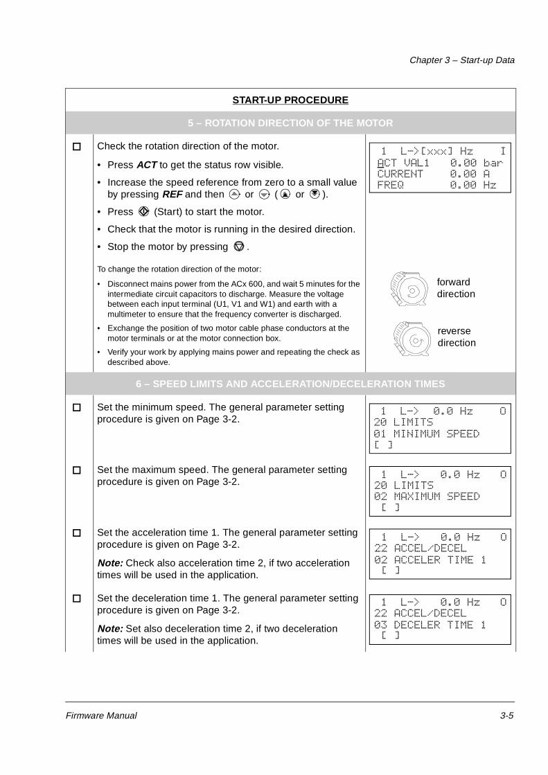
Check the rotation direction of the motor.
• Press ACT to get the status row visible.
• Increase the speed reference from zero to a small value by pressing REF and then or ( or ).
• Press (Start) to start the motor.
• Check that the motor is running in the desired direction.
• Stop the motor by pressing .
To change the rotation direction of the motor:
• Disconnect mains power from the ACx 600, and wait 5 minutes for the intermediate circuit capacitors to discharge. Measure the voltage between each input terminal (U1, V1 and W1) and earth with a multimeter to ensure that the frequency converter is discharged.
• Exchange the position of two motor cable phase conductors at the motor terminals or at the motor connection box.
• Verify your work by applying mains power and repeating the check as described above.
6 – SPEED LIMITS AND ACCELERATION/DECELERATION TIMES
Set the minimum speed. The general parameter setting procedure is given on Page 3-2.
Set the maximum speed. The general parameter setting procedure is given on Page 3-2.
Set the acceleration time 1. The general parameter setting procedure is given on Page 3-2.
Note: Check also acceleration time 2, if two acceleration times will be used in the application.
Set the deceleration time 1. The general parameter setting procedure is given on Page 3-2.
Note: Set also deceleration time 2, if two deceleration times will be used in the application.
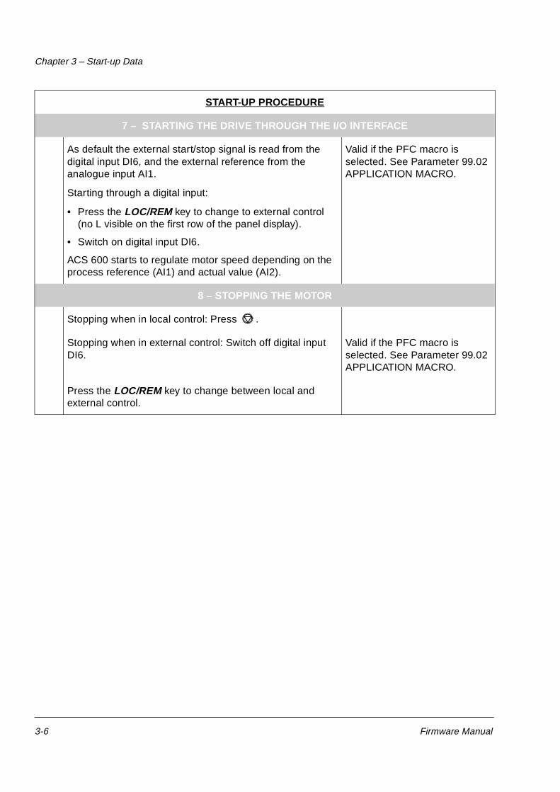
As default the external start/stop signal is read from the digital input DI6, and the external reference from the analogue input AI1.
Starting through a digital input:
• Press the LOC/REM key to change to external control (no L visible on the first row of the panel display).
• Switch on digital input DI6.
ACS 600 starts to regulate motor speed depending on the process reference (AI1) and actual value (AI2).
Valid if the PFC macro is selected. See Parameter 99.02 APPLICATION MACRO.
8 – STOPPING THE MOTOR
Stopping when in local control: Press .
Stopping when in external control: Switch off digital input DI6.
Valid if the PFC macro is selected. See Parameter 99.02 APPLICATION MACRO.
Press the LOC/REM key to change between local and external control.
START-UP PROCEDURE
Chapter 3 – Start-up Data
Firmware Manual 3-7
Start-up Data Parameters
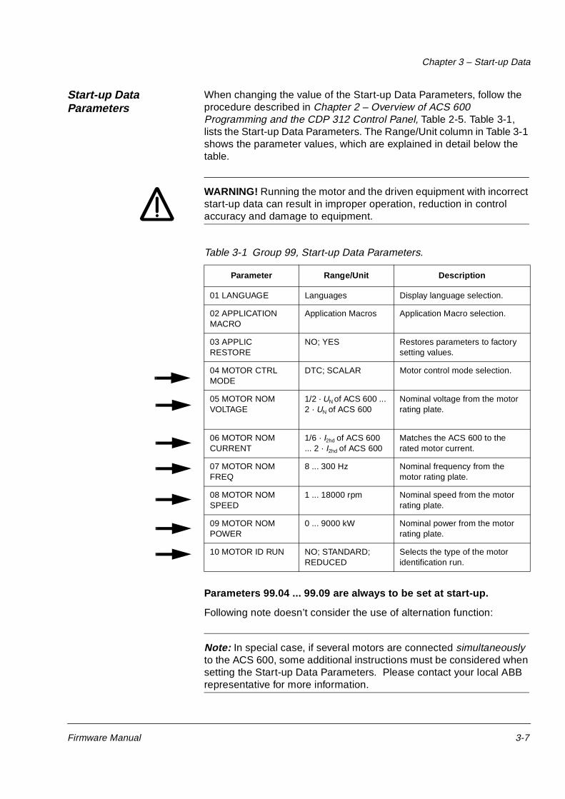
When changing the value of the Start-up Data Parameters, follow the procedure described in Chapter 2 – Overview of ACS 600 Programming and the CDP 312 Control Panel, Table 2-5. Table 3-1, lists the Start-up Data Parameters. The Range/Unit column in Table 3-1 shows the parameter values, which are explained in detail below the table.
WARNING! Running the motor and the driven equipment with incorrect start-up data can result in improper operation, reduction in control accuracy and damage to equipment.
Table 3-1 Group 99, Start-up Data Parameters.
Parameters 99.04 ... 99.09 are always to be set at start-up.
Following note doesn’t consider the use of alternation function:
Note: In special case, if several motors are connected simultaneously to the ACS 600, some additional instructions must be considered when setting the Start-up Data Parameters. Please contact your local ABB representative for more information.
Parameter Range/Unit Description
01 LANGUAGE Languages Display language selection.
02 APPLICATION MACRO
Application Macros Application Macro selection.
03 APPLIC RESTORE
NO; YES Restores parameters to factory setting values.
04 MOTOR CTRL MODE
DTC; SCALAR Motor control mode selection.
05 MOTOR NOM VOLTAGE
1/2 · UN of ACS 600 ... 2 · UN of ACS 600
Nominal voltage from the motor rating plate.
06 MOTOR NOM CURRENT
1/6 · I2hd of ACS 600 ... 2 · I2hd of ACS 600
Matches the ACS 600 to the rated motor current.
07 MOTOR NOM FREQ
8 ... 300 Hz Nominal frequency from the motor rating plate.
08 MOTOR NOM SPEED
1 ... 18000 rpm Nominal speed from the motor rating plate.
09 MOTOR NOM POWER
0 ... 9000 kW Nominal power from the motor rating plate.
10 MOTOR ID RUN NO; STANDARD; REDUCED
Selects the type of the motor identification run.
Chapter 3 – Start-up Data
3-8 Firmware Manual
99.01 LANGUAGE The ACS 600 displays all information in the language you select. The Panel shows 11 alternatives but actually a set of four languages is loaded into the memory of the ACS 600. The language sets used are:
• English (UK & Am), French, Spanish, Portuguese
• English (UK & Am), German, Italian, Dutch
• English (UK & Am), Danish, Swedish, Finnish
If English (Am) is selected, the unit of power used is HP instead of kW.
99.02 APPLICATIONMACRO
This parameter is used to select the Application Macro which will configure the ACS 600 for a particular application. Refer to Chapter 5 – Application Macros for a list and description of available Application Macros. There is also a selection for saving the current settings as a User Macro (USER 1 SAVE or USER 2 SAVE), and recalling these settings (USER 1 LOAD or USER 2 LOAD).
There are Parameters that are not included in Macros. See section 99.03 APPLIC RESTORE.
Note: User Macro load restores also the motor settings of the Start-up Data group and the results of the Motor Identification. Check that the settings correspond to the motor used.
99.03 APPLIC RESTORE Selection YES restores the original settings of an application macro as follows:
• If a Pump and Fan Control or Hand/Auto Macro is selected, the parameter values excluding Groups 98 and 99 are restored to the settings loaded at the factory.
• If User Macro 1 or 2 is in use, the parameter values are restored to the last saved values. In addition, the last saved results of the motor identification are restored (see Chapter 5 – Application Macros). Exceptions: Settings of Parameters 16.05 USER MACRO IO CHG (O) and 99.02 APPLICATION MACRO remain unchanged.
Note: The parameter settings and the results of motor identification are restored according to the same principles when a macro is changed to another.
Chapter 3 – Start-up Data
Firmware Manual 3-9
99.04 MOTOR CTRLMODE
This parameter sets the motor control mode.
DTCThe DTC (Direct Torque Control) mode is suitable for most applications. The ACS 600 performs precise speed and torque control of standard squirrel cage motors without pulse encoder feedback.
If several motors are connected to the ACS 600, there are certain restrictions on the usage of DTC. Please contact your local ABB representative for more information.
SCALAR
The scalar control should be selected in those special cases in which the DTC cannot be applied. The SCALAR control mode is recommended for multimotor drives when number of motors connected to the ACS 600 is variable. The SCALAR control is also recommended when the nominal current of the motor is less than 1/6 of the nominal current of the inverter or the inverter is used for test purposes with no motor connected.
The outstanding motor control accuracy of DTC cannot be achieved in the scalar control mode. The differences between the SCALAR and DTC control modes are discussed further in this manual in relevant parameter lists.
There are some standard features that are disabled in the SCALAR control mode: Motor Identification Run (Group 99), Frequency Limits (Group 20), Torque Limit (Group 20), DC Magnetizing (Group 21), Speed Controller Tuning (Group 23), Flux Optimization (Group 26), Flux Braking (Group 26), Underload Function (Group 30), Motor Phase Loss Protection (Group 30), Motor Stall Protection (Group 30). Furthermore, a rotating motor cannot be started or fast motor restart performed even it is possible to select the automatic start function (21.01 START FUNCTION (O)).
99.05 MOTOR NOMVOLTAGE
This parameter matches the ACS 600 with the nominal voltage of the motor as indicated on the motor rating plate.
Note: It is not allowed to connect a motor with nominal voltage less than 1/2 · UN or more than 2 · UN of the ACS 600.
99.06 MOTOR NOMCURRENT
This parameter matches the ACS 600 to the rated motor current. The allowed range 1/6 · I2hd ... 2 · I2hd of ACS 600 is valid for DTC motor control mode. In SCALAR mode the allowed range is 0 · I2hd ... 2 · I2hd of ACS 600.
Correct motor run requires that the magnetizing current of the motor does not exceed 90 per cent of the nominal current of the inverter.
99.07 MOTOR NOMFREQUENCY
This parameter matches the ACS 600 to the rated motor frequency, adjustable from 8 Hz to 300 Hz.
Chapter 3 – Start-up Data
3-10 Firmware Manual
99.08 MOTOR NOMSPEED
This parameter matches the ACS 600 to the nominal speed as indicated on the motor rating plate.
Note: It is very important to set this parameter exactly to the value given on the motor rating plate to guarantee proper operation of the drive. The motor synchronous speed or another approximate value must not be given instead!
Note: The speed limits in Group 20 Limits are linked to the setting of 99.08 MOTOR NOM SPEED. If value of Parameter 99.08 MOTOR NOM SPEED is changed, the speed limit settings change automatically as well.
99.09 MOTOR NOMPOWER
This parameter matches the ACS 600 to the rated power of the motor, adjustable between 0 kW and 9000 kW.
99.10 MOTOR ID RUN This parameter is used to initiate the Motor Identification Run. During the run, the ACS 600 will identify the characteristics of the motor for optimum motor control. The ID Run takes about one minute.
The ID run cannot be performed if the scalar control mode is selected (Parameter 99.04 MOTOR CTRL MODE is set to SCALAR).
NO The Motor ID Run is not performed. This can be selected in most applications. The motor model is calculated at first start by magnetising the motor for 20 to 60 s at zero speed.
Note: The ID Run (Standard or Reduced) should be selected if:
• operation point is near zero speed
• operation at torque range above the motor nominal torque within wide speed range and without any pulse encoder (i.e. without any measured speed feedback) is required.
STANDARD Performing the Standard Motor ID Run guarantees that the best possible control accuracy is achieved. The motor must be de-coupled from the driven equipment before performing the Standard Motor ID Run.
REDUCEDThe Reduced Motor ID Run should be selected instead of the Standard ID Run:
• if mechanical losses are higher than 20 % (i.e. the motor cannot be de-coupled from the driven equipment)
Chapter 3 – Start-up Data
Firmware Manual 3-11
• if flux reduction is not allowed while the motor is running (i.e. in case of a braking motor in which the brake switches on if the flux is reduced below a certain level).
Note: Check the rotation direction of the motor before starting the Motor ID Run. During the run the motor will rotate in the forward direction.
Note: If the Pump and Fan Control Macro is selected (parameter 99.02 APPLICATION MACRO) and the Interlocks are taken in use (Parameter 81.20 INTERLOCKS (O) is set to ON), the interlock signal of motor no. 1(*) has to be connected to digital input DI2. Otherwise the Motor ID Run cannot be started.
(*) speed regulated motor
WARNING! The motor will run at up to approximately 50 % ... 80 % of the nominal speed during the Motor ID Run. ENSURE THAT IT IS SAFE TO RUN THE MOTOR BEFORE PERFORMING THE MOTOR ID RUN!
ID Run Procedure To perform the Motor ID Run:
Note: If parameter values (Group 10 to 98) are changed before the ID Run, check that the new settings meet the following conditions:
• 20.01 MINIMUM FREQUENCY < 0.
• 20.02 MAXIMUM FREQUENCY > 80 % of motor rated frequency.
• 20.03 MAXIMUM CURRENT > 100*Ihd.
• 20.04 MAXIMUM TORQUE > 50 %.
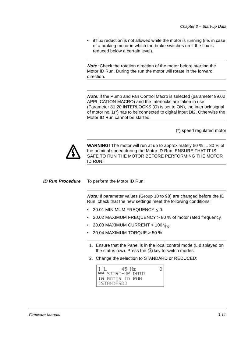
1. Ensure that the Panel is in the local control mode (L displayed on the status row). Press the key to switch modes.
2. Change the selection to STANDARD or REDUCED:
LOC
REM
1 L 45 Hz O99 START-UP DATA10 MOTOR ID RUN[STANDARD]
Chapter 3 – Start-up Data
3-12 Firmware Manual
3. Press ENTER to verify selection. The following message will be displayed:
4. To start the ID Run, press the key. The run enable signal must be active (see Parameter 16.01 RUN ENABLE (O) ). If the PFC Macro is selected, the interlocks must be on (see Parameter 81.20 INTERLOCKS (O)).
In general it is recommended not to press any control panel keys during the ID run. However:
• The Motor ID Run can be stopped at any time by pressing the Control Panel key or removing the Run enable signal.
• After the ID Run is started with the key, it is possible to monitor the actual values by first pressing the ACT key and then the key.
Warning when the ID Run is started
Warning during the ID Run Warning after a successfully completed ID Run
1 L 45.0 Hz I
ACS 600 55 kW
**WARNING**MOTOR STARTS
1 L 45.0 Hz I
ACS 600 55 kW
**WARNING**ID RUNNING
1 L 45.0 Hz I
ACS 600 55 kW
**WARNING**ID DONE
1 L 45.0 Hz OACS 600 55 kW**WARNING**ID RUN SEL
Firmware Manual 4-1
Chapter 4 – Control Operation
Overview This chapter describes the Actual Signals, the Fault History, and the Local and External control modes.
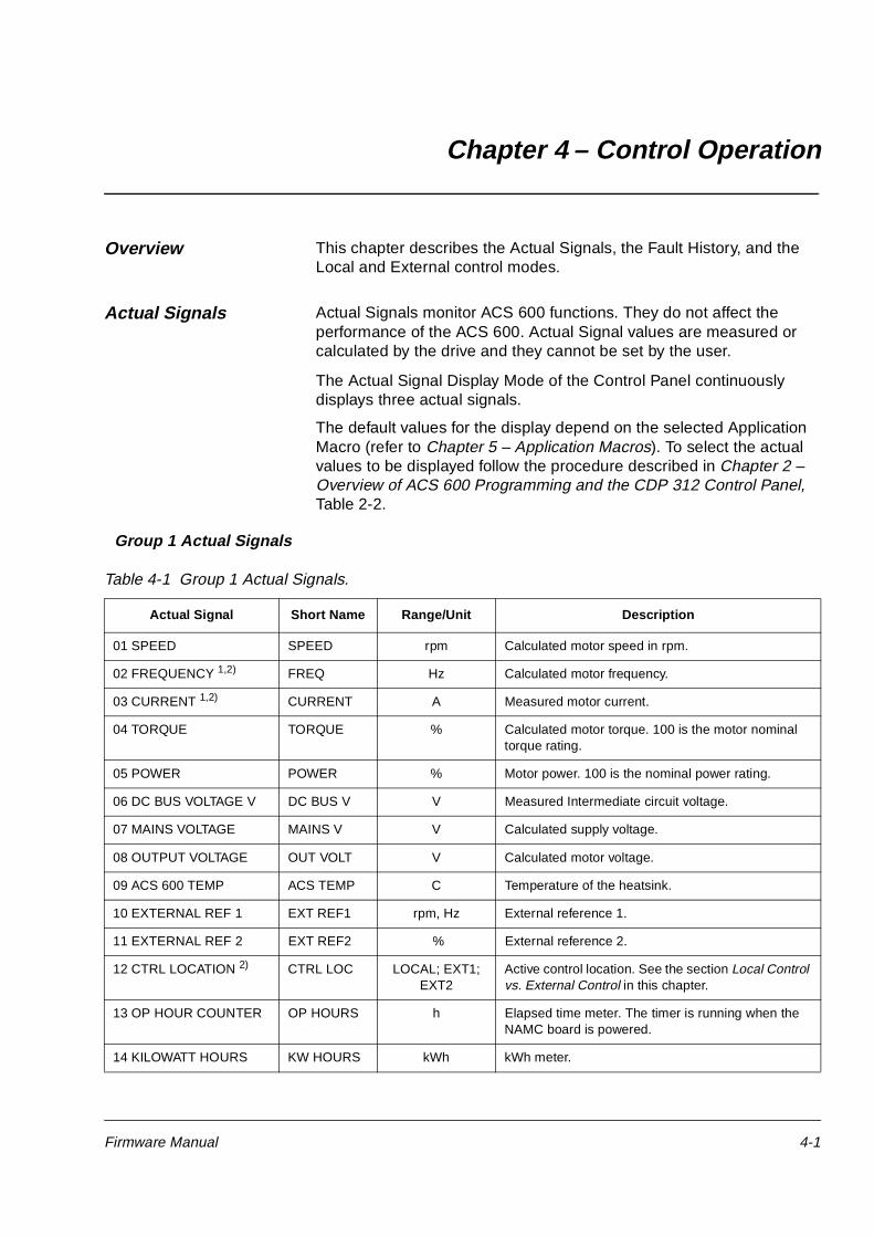
Actual Signals Actual Signals monitor ACS 600 functions. They do not affect the performance of the ACS 600. Actual Signal values are measured or calculated by the drive and they cannot be set by the user.
The Actual Signal Display Mode of the Control Panel continuously displays three actual signals.
The default values for the display depend on the selected Application Macro (refer to Chapter 5 – Application Macros). To select the actual values to be displayed follow the procedure described in Chapter 2 – Overview of ACS 600 Programming and the CDP 312 Control Panel, Table 2-2.
Group 1 Actual Signals
Table 4-1 Group 1 Actual Signals.
Actual Signal Short Name Range/Unit Description
01 SPEED SPEED rpm Calculated motor speed in rpm.
02 FREQUENCY 1,2) FREQ Hz Calculated motor frequency.
03 CURRENT 1,2) CURRENT A Measured motor current.
04 TORQUE TORQUE % Calculated motor torque. 100 is the motor nominal torque rating.
05 POWER POWER % Motor power. 100 is the nominal power rating.
06 DC BUS VOLTAGE V DC BUS V V Measured Intermediate circuit voltage.
07 MAINS VOLTAGE MAINS V V Calculated supply voltage.
08 OUTPUT VOLTAGE OUT VOLT V Calculated motor voltage.
09 ACS 600 TEMP ACS TEMP C Temperature of the heatsink.
Active control location. See the section Local Control vs. External Control in this chapter.
13 OP HOUR COUNTER OP HOURS h Elapsed time meter. The timer is running when the NAMC board is powered.
14 KILOWATT HOURS KW HOURS kWh kWh meter.
Chapter 4 – Control Operation
4-2 Firmware Manual
1)Default setting for Pump and Fan Control (PFC) Macro.2)Default setting for Hand/Auto Macro.
15 APPL BLOCK OUTPUT
APPL OUT % Application block output signal. See Figure 4-2.
16 DI6-1 STATUS DI6-1 Status of standard digital inputs (DI6-1) and the optional PFC extension module digital input 1(DI7). 0 V = “0” ; +24 VDC = “1”
17 AI1 (V) AI1 (V) V Value of analogue input 1.
18 AI2 (mA) AI2 (mA) mA Value of analogue input 2.
19 AI3 (mA) AI3 (mA) mA Value of analogue input 3.
20 RO3-1 STATUS RO3-1 Status of relay outputs (RO3-1) and the optional PFC extension module digital outputs (RO5-4). 1= relay is energised ; 0 = relay is de-energised
21 AO1 (mA) AO1 (mA) mA Value of analogue output 1.
22 AO2 (mA) AO2 (mA) mA Value of analogue output 2.
23 ACTUAL VALUE 1 1) ACT VAL1 NO; Bar; %;C; mg/l; kPa
Value of the process feedback signal no.1 received by the process PI Controller. (Ref. to Par 80.12 ACTUAL 1 UNIT)
24 ACTUAL VALUE 2 ACT VAL2 NO; Bar; %;C; mg/l; kPa
Value of the process feedback signal no.2 received by the process PI Controller. (Ref. to Par 80.14 ACTUAL 2 UNIT)
25 CONTROL DEVIATION CONT DEV % Deviation of the PI Controller (Difference between the process reference value and the process actual value of the process PI controller).
26 PFC OPERATION TIME
PFC OP T h Time counted from the latest Autochange. See Parameter Group 81 PFC Control.
27 ACTUAL FUNC OUT ACTUAL F Result of the arithmetic operation selected with Parameter 80.04 ACTUAL VALUE SEL
Actual Signal Short Name Range/Unit Description
Chapter 4 – Control Operation
Firmware Manual 4-3
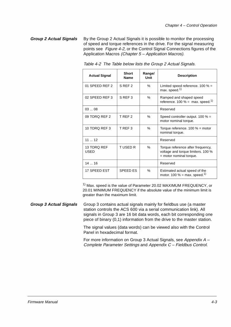
Group 2 Actual Signals By the Group 2 Actual Signals it is possible to monitor the processing of speed and torque references in the drive. For the signal measuring points see Figure 4-2, or the Control Signal Connections figures of the Application Macros (Chapter 5 – Application Macros).
Table 4-2 The Table below lists the Group 2 Actual Signals.
1) Max. speed is the value of Parameter 20.02 MAXIMUM FREQUENCY, or 20.01 MINIMUM FREQUENCY if the absolute value of the minimum limit is greater than the maximum limit.
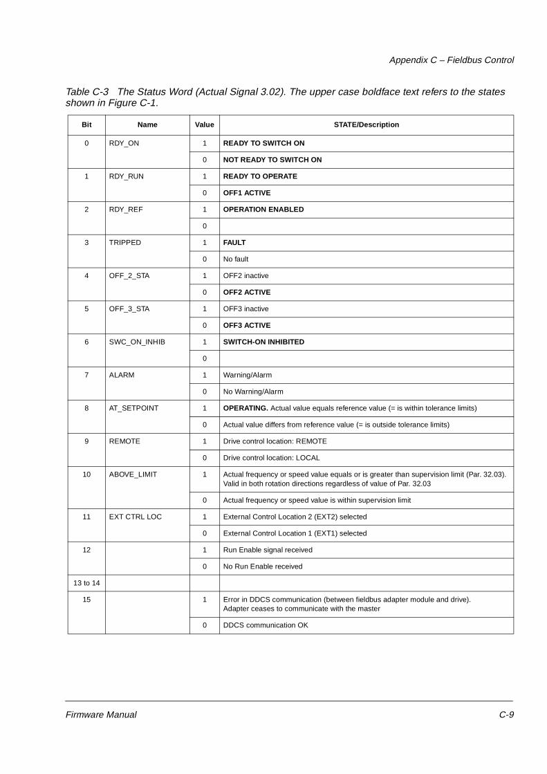
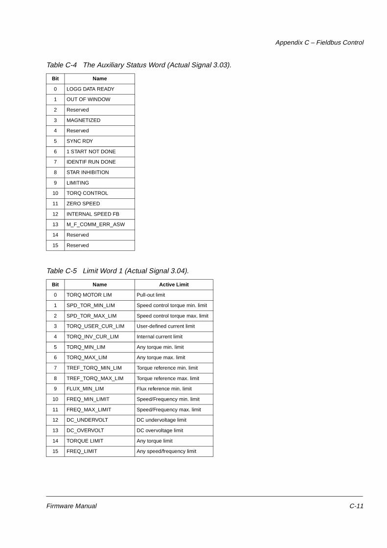
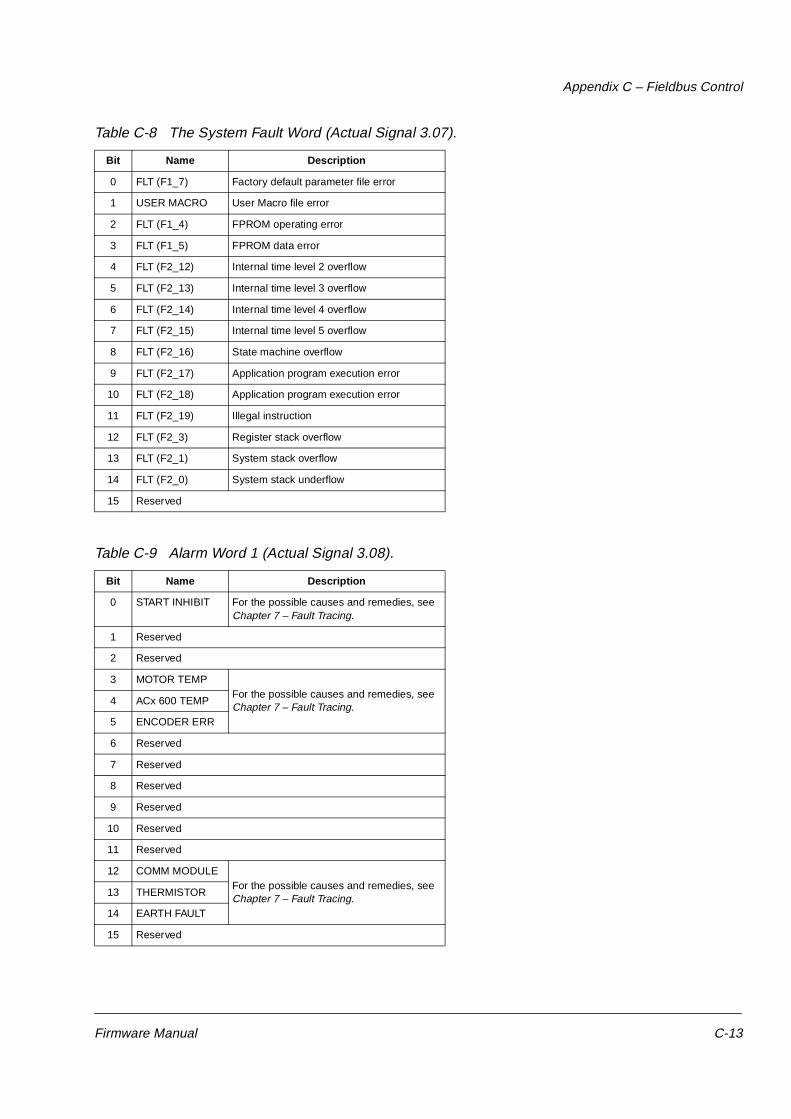
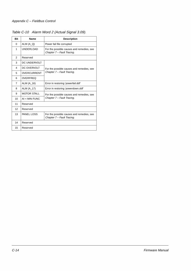
Group 3 Actual Signals Group 3 contains actual signals mainly for fieldbus use (a master station controls the ACS 600 via a serial communication link). All signals in Group 3 are 16 bit data words, each bit corresponding one piece of binary (0,1) information from the drive to the master station.
The signal values (data words) can be viewed also with the Control Panel in hexadecimal format.
For more information on Group 3 Actual Signals, see Appendix A – Complete Parameter Settings and Appendix C – Fieldbus Control.
Actual SignalShort Name
Range/Unit
Description
01 SPEED REF 2 S REF 2 % Limited speed reference. 100 % = max. speed.1)
02 SPEED REF 3 S REF 3 % Ramped and shaped speed reference. 100 % = max. speed.1)
03 ... 08 Reserved
09 TORQ REF 2 T REF 2 % Speed controller output. 100 % = motor nominal torque.
10 TORQ REF 3 T REF 3 % Torque reference. 100 % = motor nominal torque.
11 ... 12 Reserved
13 TORQ REF USED
T USED R % Torque reference after frequency, voltage and torque limiters. 100 % = motor nominal torque.
14 ... 16 Reserved
17 SPEED EST SPEED ES % Estimated actual speed of the motor. 100 % = max. speed.1)
Chapter 4 – Control Operation
4-4 Firmware Manual
Fault History The Fault History includes information on the 16 most recent faults and warnings that occurred in the ACS 600 (or 64, if the power is not switched off meanwhile). The description of the fault and the total power-on time are available. The power-on time is calculated always when the NAMC board of the ACS 600 is powered.
Chapter 2 – Overview of ACS 600 Programming and the CDP 312 Control Panel, Table 2-4, describes how to display and clear the Fault History from the Control Panel.
Local Control vs. External Control
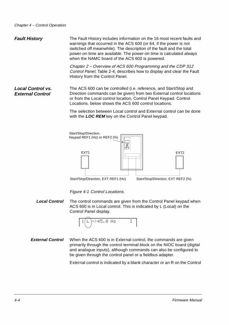
The ACS 600 can be controlled (i.e. reference, and Start/Stop and Direction commands can be given) from two External control locations or from the Local control location, Control Panel Keypad. Control Locations. below shows the ACS 600 control locations.
The selection between Local control and External control can be done with the LOC REM key on the Control Panel keypad.
Figure 4-1 Control Locations.
Local Control The control commands are given from the Control Panel keypad when ACS 600 is in Local control. This is indicated by L (Local) on the Control Panel display.
External Control When the ACS 600 is in External control, the commands are given primarily through the control terminal block on the NIOC board (digital and analogue inputs), although commands can also be configured to be given through the control panel or a fieldbus adapter.
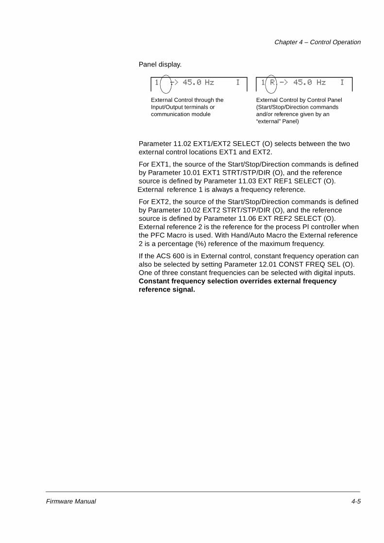
External control is indicated by a blank character or an R on the Control
Parameter 11.02 EXT1/EXT2 SELECT (O) selects between the two external control locations EXT1 and EXT2.
For EXT1, the source of the Start/Stop/Direction commands is defined by Parameter 10.01 EXT1 STRT/STP/DIR (O), and the reference source is defined by Parameter 11.03 EXT REF1 SELECT (O). External reference 1 is always a frequency reference.
For EXT2, the source of the Start/Stop/Direction commands is defined by Parameter 10.02 EXT2 STRT/STP/DIR (O), and the reference source is defined by Parameter 11.06 EXT REF2 SELECT (O). External reference 2 is the reference for the process PI controller when the PFC Macro is used. With Hand/Auto Macro the External reference 2 is a percentage (%) reference of the maximum frequency.
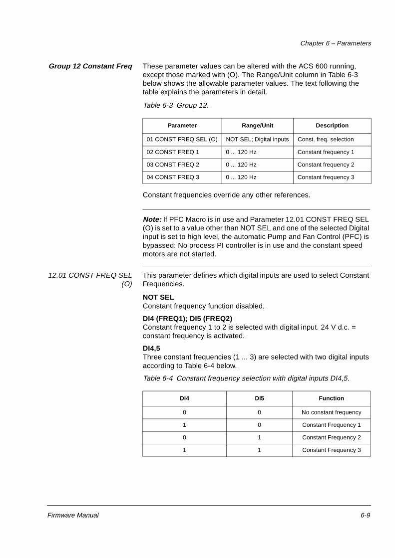
If the ACS 600 is in External control, constant frequency operation can also be selected by setting Parameter 12.01 CONST FREQ SEL (O). One of three constant frequencies can be selected with digital inputs. Constant frequency selection overrides external frequency reference signal.
External Control through the Input/Output terminals or communication module
1 R -> 45.0 Hz I 1 -> 45.0 Hz I
External Control by Control Panel(Start/Stop/Direction commands and/or reference given by an “external” Panel)
Chapter 4 – Control Operation
4-6 Firmware Manual
Figure 4-2 Selecting control location and control source.
DI1-6,COMM.MOD.
11EXTERNALREF 2
Start/Stop/Direction source selection
10.01 EXT1STRT/STP/DIR
Group 25CRITICAL FREQ
20.01 MINIMUM FREQ20.02 MAXIMUM FREQ
Group 22ACCEL/DECEL
Group 23SPEED CTRL
Speed Controller
ACS 600
AnalogueInputs
AI1...AI3
DigitalInputs
DI1...DI6
CH0 NAMCboard
(COMM.MODULE)
Reference source selection
Reference selection
11.06 EXTREF2 SELECT
Group 12CONSTANT
FREQ
11.03 EXTREF1 SELECT
12.01 CONSTFREQ SEL
11.01 KEYPADREF SELECT
11.02 EXT1/EXT2 SELECT
10EXTERNALREF 1
EXT1
KEYPAD
EXT2
CONTROLPANEL
REF
LOC
REM
EXT1
NOT SEL
EXTERNAL
NOT SEL
KEYPAD
KEYPAD
KEYPAD
KEYPAD
KEYPAD
KEYPAD
DI1-6, COMM.MOD.
AI1-3,DI1-6, COMM.MOD.
EXTERNAL REF2(%)
REF1(Hz)
NOT SEL
REQUEST
FORWARD
REVERSE
10.02 EXT2STRT/STP/DIR
10.03DIRECTION
16.01RUN ENABLE
AI1-3,DI1-6, COMM.MOD.
PFCAPPLICATION
15 APPL BLOCK OUTPUT
EXT2
EXTERNAL
YES, DI1-6, COMM.MOD.
20.04 MAXIMUM TORQUE
Torque Controller
2.13TORQ REF USED
2.10TORQ REF 3
2.09TORQ REF 2
Start/Stop
Direction
Start/Stop, Direction
Process ref.
Hand/Auto
PFC
Frequencyreference
Firmware Manual 5-1
Chapter 5 – Application Macros
Overview This chapter contains descriptions of Pump and Fan Control (PFC), Hand/Auto and two User macros.The default Parameter Settings are given in Appendix A – Complete Parameter Settings.
Application Macros Application Macros are preprogrammed parameter sets. Using the Application Macros enables a quick and easy start-up of the ACS 600.
Application Macros minimise the number of different parameters to be set during start-up. All parameters have factory-set default values. The Pump and Fan Control (PFC) Macro is the factory-set default macro.
While starting up the ACS 600, you can select either PFC or Hand/Auto Macro as the default for your ACS 600.
The Application Macro default values are chosen to represent the average values in a typical application. Check that the default settings match your requirements and customise the settings when appropriate. All inputs and outputs are programmable.
Note: When you change the parameter values of the PFC or Hand/Auto macro, the new settings become active immediately and stay active even if the power of the ACS 600 is switched off and on. However, the default parameter settings of each macro loaded at the factory are still available. The default settings are restored when Parameter 99.03 APPLIC RESTORE is changed to YES, or if the macro is changed.
Note: There are certain parameters that remain the same even though the macro were changed to another, or the default settings of the macro were restored. For more information, see Chapter 3 – Start-up Data, section 99.03 APPLIC RESTORE.
Chapter 5 – Application Macros
5-2 Firmware Manual
Pump and Fan Control (PFC) Macro
Pump and Fan Control (PFC) macro can operate a pump (or fan or compressor) station with one to four parallel pumps. The control principle of a two-pump station is as follows:
• The motor of the pump no. 1 is connected to the ACS 600. The capacity of the pump is controlled by varying the motor speed.
• The motor of the pump no. 2 is connected direct on-line. The pump can be switched on and off by the ACS 600 when necessary.
• The process reference and actual value are fed to the PI controller included in the PFC macro. The PI controller adjusts the speed (frequency) of the first pump such that the process actual value follows the reference. When the frequency reference of the process PI controller exceeds the limit set by the user, the PFC macro automatically starts the second pump. When the frequency falls below the limit set by the user, the PFC macro automatically stops the second pump.
• Using the digital inputs of the ACS 600, an interlocking function can be implemented; the PFC macro detects if a pump is switched off and starts the other pump instead.
• The PFC macro makes automatic pump alternation possible (not in use in Figure 5-1). Thus each pump can be run with an equal duty time. For more information on the alternation system and the other useful features such as Sleep function, Constant reference value, Reference steps and Regulator by-pass, see Chapter 6 – Parameters (Group 81 PFC Control).
As default ACS 600 receives process reference (setpoint) through analogue input 1, process actual value through analogue input 2 and Start/Stop commands through digital input 6. The interlocks are connected to digital input 2 (Motor 1) and digital input 3 (Motor 2).
The default output signals are given through analogue output 1 (frequency) and 2 (actual value of the process PI controller).
If the Control Panel is in local control mode (L on the first row of the display), ACS 600 follows the frequency reference given from the Panel. The automatic Pump and Fan Control (PFC) is bypassed: No process PI controller is in use and the constant speed motors are not started.
Chapter 5 – Application Macros
Firmware Manual 5-3
Operation Diagram
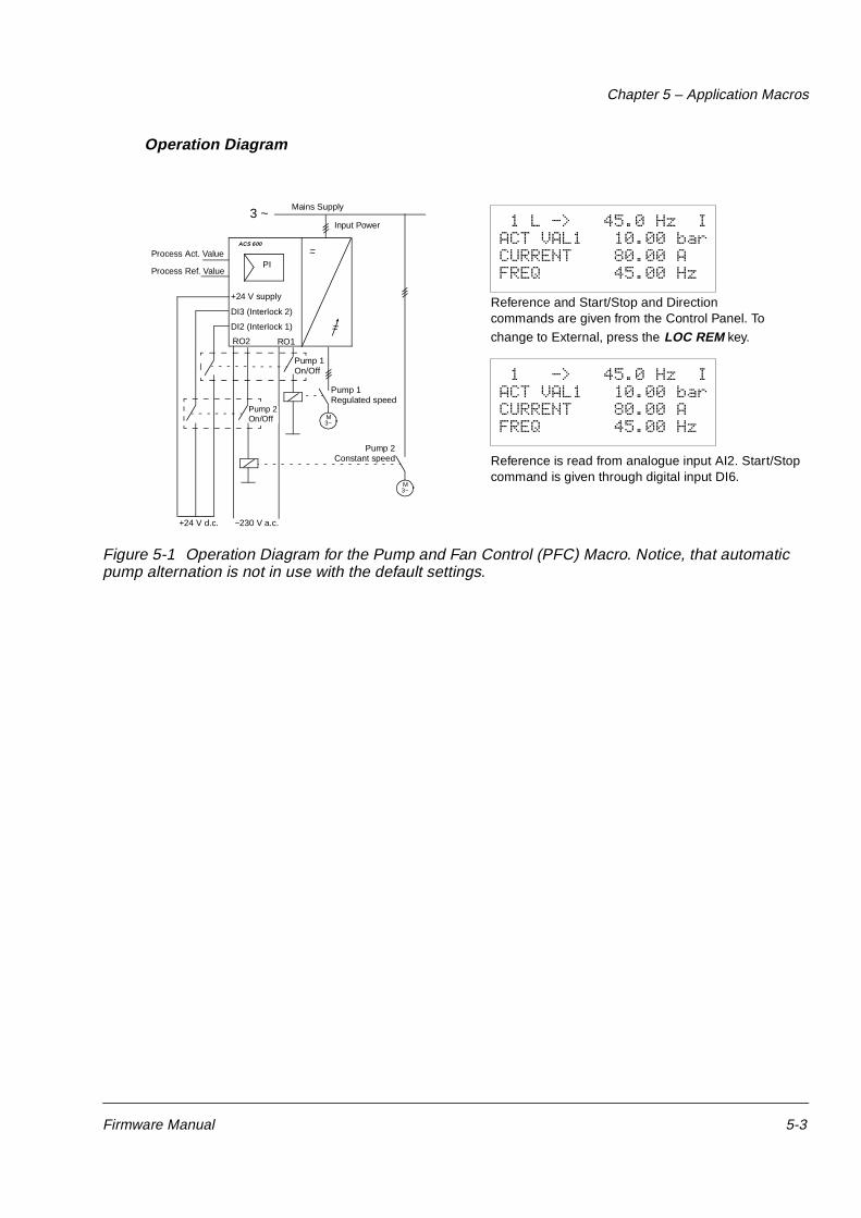
Figure 5-1 Operation Diagram for the Pump and Fan Control (PFC) Macro. Notice, that automatic pump alternation is not in use with the default settings.
Process Act. Value
Process Ref. Value
DI3 (Interlock 2)
DI2 (Interlock 1)
RO2 RO1
~~
~~
M3~
+24 V d.c.
Input Power
PI
ACS 600
Pump 1Regulated speed
Pump 2Constant speed
~230 V a.c.
1 L -> 45.0 Hz IACT VAL1 10.00 bar CURRENT 80.00 AFREQ 45.00 Hz
Reference and Start/Stop and Direction commands are given from the Control Panel. To
change to External, press the LOC REM key.
Reference is read from analogue input AI2. Start/Stop command is given through digital input DI6.
1 -> 45.0 Hz IACT VAL1 10.00 bar CURRENT 80.00 AFREQ 45.00 Hz
M3~
Mains Supply3 ~
+24 V supply
Pump 2On/Off
Pump 1On/Off
Chapter 5 – Application Macros
5-4 Firmware Manual
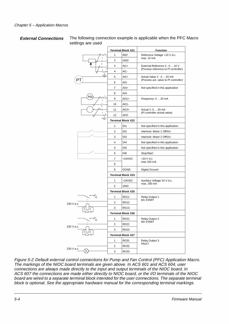
External Connections The following connection example is applicable when the PFC Macro settings are used
Figure 5-2 Default external control connections for Pump and Fan Control (PFC) Application Macro. The markings of the NIOC board terminals are given above. In ACS 601 and ACS 604, user connections are always made directly to the input and output terminals of the NIOC board. In ACS 607 the connections are made either directly to NIOC board, or the I/O terminals of the NIOC board are wired to a separate terminal block intended for the user connections. The separate terminal block is optional. See the appropriate hardware manual for the corresponding terminal markings.
230 V a.c.
A1
A2
3
230 V a.c.
A1
A2
3
PT
Hz
Terminal Block X21 Function
1 REF Reference Voltage +10 V d.c.max. 10 mA
2 GND
3 AI1+ External Reference 2 : 0 ... 10 V(Process reference to PI controller)
4 AI1-
5 AI2+ Actual Value 1: 4 ... 20 mA(Process act. value to PI controller)
6 AI2-
7 AI3+ Not specified in this application
8 AI3-
9 AO1+ Frequency: 0 ... 20 mA
10 AO1-
11 AO2+ Actual 1: 0 ... 20 mA(PI controller actual value)
12 AO2-
Terminal Block X22
1 DI1 Not specified in this application
2 DI2 Interlock: Motor 1 Off/On
3 DI3 Interlock: Motor 2 Off/On
4 DI4 Not specified in this application
5 DI5 Not specified in this application
6 DI6 Stop/Start
7 +24VDC +24 V d.c max 100 mA
8
9 DGND Digital Ground
Terminal Block X23
1 +24VDC Auxiliary Voltage 24 V d.c.max. 250 mA
2 GND
Terminal Block X25
1 RO11 Relay Output 1M1 START
2 RO12
3 RO13
Terminal Block X26
1 RO21 Relay Output 2M2 START
2 RO22
3 RO23
Terminal Block X27
1 RO31 Relay Output 3FAULT
2 RO32
3 RO33230 V a.c.
Chapter 5 – Application Macros
Firmware Manual 5-5
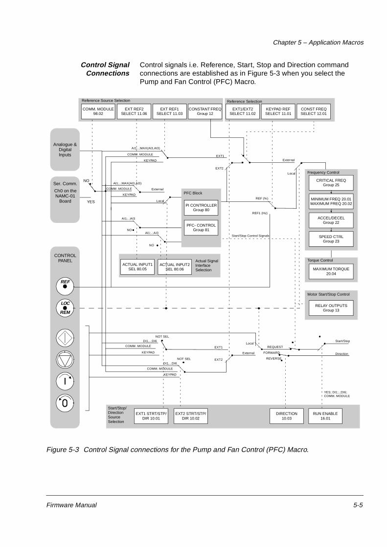
Control SignalConnections
Control signals i.e. Reference, Start, Stop and Direction command connections are established as in Figure 5-3 when you select the Pump and Fan Control (PFC) Macro.
Figure 5-3 Control Signal connections for the Pump and Fan Control (PFC) Macro.
Actual Signal InterfaceSelection
EXT1
EXT2
External
LOC
REF
REM
LocalREF (%)
REF1 (Hz)
COMM. MODULE
KEYPAD
COMM. MODULE
KEYPAD
NOT SEL
EXT1
EXT2
Local
External
REQUEST
FORWARD
REVERSE
Start/Stop
Direction
EXT1 STRT/STP/DIR 10.01
DIRECTION 10.03
RUN ENABLE 16.01
Start/Stop/Direction Source Selection
Reference Source Selection Reference Selection
MAXIMUM TORQUE 20.04
Torque Control
EXT1/EXT2 SELECT 11.02
CONST FREQ SELECT 12.01
KEYPAD REF SELECT 11.01
CONTROL PANEL
Ser. Comm.
Ch0 on the NAMC-01
Board
Analogue & DigitalInputs
External
AI1;..;MAX(AI3,AI3)
COMM. MODULE
KEYPAD
COMM. MODULE
KEYPAD
NOT SEL
SPEED CTRLGroup 23
EXT2 STRT/STP/DIR 10.02
CRITICAL FREQGroup 25
MINIMUM FREQ 20.01MAXIMUM FREQ 20.02
ACCEL/DECELGroup 22
Frequency Control
NO
PFC Block
PI CONTROLLERGroup 80
PFC- CONTROLGroup 81
ACTUAL INPUT1 SEL 80.05
ACTUAL INPUT2 SEL 80.06
NO
AI1;..;AI3
AI1;..;AI3
DI1,..;DI6
DI1,..;DI6
YES
NO
EXT REF2 SELECT 11.06
EXT REF1 SELECT 11.03
CONSTANT FREQ Group 12
COMM. MODULE 98.02
AI1;..;MAX(AI3,AI3)
YES; DI1;..;DI6;COMM. MODULE
RELAY OUTPUTSGroup 13
Start/Stop Control Signals
Motor Start/Stop Control
Local
Chapter 5 – Application Macros
5-6 Firmware Manual
Hand/Auto Application Macro
Start/Stop commands and reference settings can be given from one of two external control locations, EXT1 (Hand) or EXT2 (Auto). The Start/Stop commands of the EXT1 (Hand) are connected to digital input DI1, and the reference signal is connected to analogue input AI1. The Start/Stop commands of the EXT2 (Auto) are connected to digital input DI6, and the reference signal is connected to analogue input AI2. The selection between EXT1 and EXT2 is dependent on the status of digital input DI5. The drive is frequency controlled.
Frequency reference and Start/Stop commands can also be given from the Control Panel keypad.
Frequency reference in Auto Control (EXT2) is given as a percentage of the maximum frequency of the drive (see parameters 11.07 EXT REF2 MINIMUM and 11.08 EXT REF2 MAXIMUM).
Two analogue and three relay output signals are available on terminal blocks. Default signals for the Actual Signal Display Mode of the Control Panel are FREQUENCY, CURRENT and CTRL LOC.
Operation Diagram
Figure 5-4 Operation Diagram for Hand/Auto Macro.
Hz
M3∼
Relay
Motor
EXT1 (Hz) =Input
1 L -> 45.0 Hz I
CURRENT 80.00 ACTRL LOC LOCAL
FREQ 45.00 Hz
1 -> 45.0 Hz I CURRENT 80.00 ACTRL LOC EXT1
FREQ 45.00 Hz
Power
Current
Outputs
Hand/Auto
PLCorautomationEXT2 (%) =
Frequency
Hand Control
Auto Control
Local Control: Reference, Start/Stop commands are given from the Control Panel. To change to External, press LOC REM key.
External control (Hand): Reference is read from analogue input AI1. Start/Stop commands are given through digital input DI1.
A
Chapter 5 – Application Macros
Firmware Manual 5-7
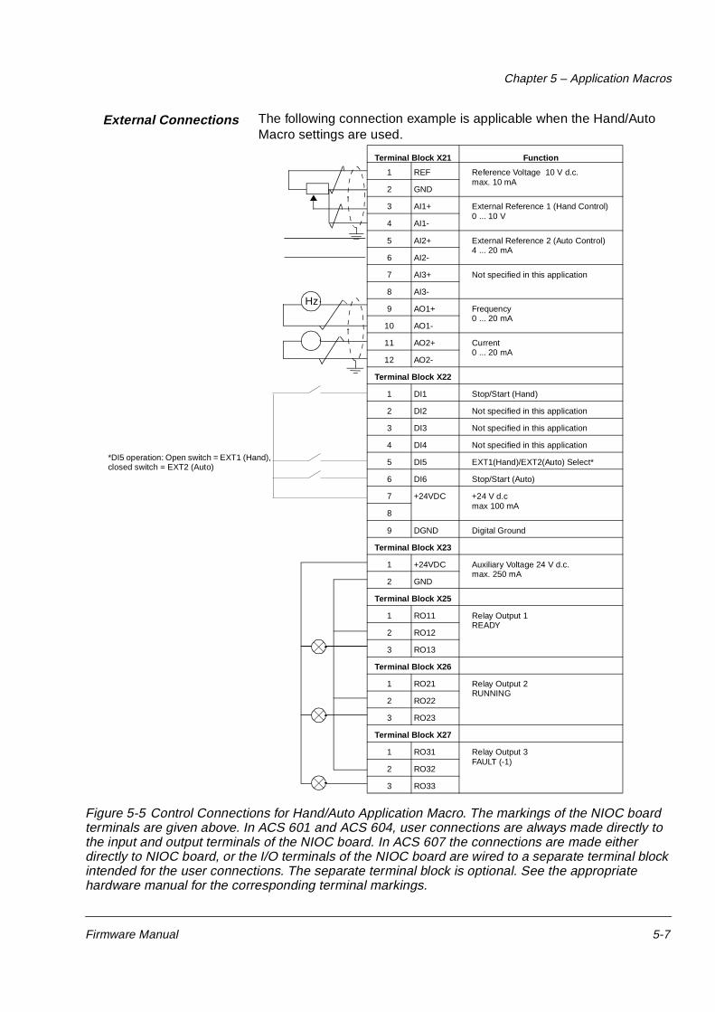
External Connections The following connection example is applicable when the Hand/Auto Macro settings are used.
Figure 5-5 Control Connections for Hand/Auto Application Macro. The markings of the NIOC board terminals are given above. In ACS 601 and ACS 604, user connections are always made directly to the input and output terminals of the NIOC board. In ACS 607 the connections are made either directly to NIOC board, or the I/O terminals of the NIOC board are wired to a separate terminal block intended for the user connections. The separate terminal block is optional. See the appropriate hardware manual for the corresponding terminal markings.
Control signals i.e. Reference, Start and Stop commands are established as in Figure 5-6 when you select the Hand/Auto Macro.
Figure 5-6 Control Signal connections for the Hand/Auto Macro.
EXTERNAL
KEYPAD
Start/Stop/Direction source selection
10.01 EXT1STRT/STP/DIR
Group 25CRITICAL FREQ
20.01 MINIMUM FREQ20.02 MAXIMUM FREQ
Group 22ACCEL/DECEL
Group 23SPEED CTRL
Frequency Control
ACS 600
AnalogueInputs
AI1...AI3
DigitalInputs
DI1...DI6
CH0 NAMCboard
(COMM.MODULE)
Reference source selection
Reference selection
11.06 EXTREF2 SELECT
Group 12CONSTANT
SPEEDS
11.03 EXTREF1 SELECT
12.01 CONSTSPEED SEL
11.01 KEYPADREF SELECT
11.02 EXT1/EXT2 SELECT
DI4(SPEED4)
EXT1DI1
KEYPAD
EXT2
CONTROLPANEL
REF
LOC
REM
AI1
EXT1
NOT SEL
NOT SEL
KEYPAD
KEYPAD
KEYPAD
KEYPAD
KEYPAD
YES
EXTERNAL
DI6
REF2(%)
REF1(Hz)
NOT SEL
REQUEST
FORWARD
REVERSE
10.02 EXT2STRT/STP/DIR
10.03DIRECTION
16.01RUN ENABLE
EXT2
DI3
AI2
EXTERNAL
Statr/Stop
Direction
Chapter 5 – Application Macros
Firmware Manual 5-9
User Macros In addition to the standard Application Macros, it is possible to create two User Macros. The User Macro allows the user to save the Parameter settings including Group 99, and the results of the motor identification into the permanent memory1), and recall the data at a later time.
To create User Macro 1:
1. Adjust the Parameters. Perform the motor identification if not yet performed.
2. Save the parameter settings and the results of the motor identification by changing Parameter 99.02 APPLICATION MACRO to USER 1 SAVE (press ENTER). The storing will take a few minutes.
To recall the User Macro:
1. Change Parameter 99.02 APPLICATION MACRO to USER 1 LOAD.
2. Press ENTER to load.
The User Macro can also be switched via digital inputs (see Parameter 16.05 USER MACRO IO CHG (O)).
Note: User Macro load restores also the motor settings of the Start-up Data group and the results of the motor identification. Check that the settings correspond to the motor used.
Example: User Macros make it possible to switch the ACS 600 between two motors without having to adjust the motor parameters and to repeat the motor identification every time the motor is changed. The user can simply adjust the settings and perform the motor identification once for both motors, and then save the data as two User Macros. When the motor is changed, only the corresponding User Macro needs to be loaded and the drive is ready to operate.
User Macro needs to be loaded and the drive is ready to operate.
1) Also the panel reference and the control location setting (Local or Remote) are saved.
Chapter 5 – Application Macros
5-10 Firmware Manual
Firmware Manual 6-1
Chapter 6 – Parameters
Overview This chapter explains the function of, and valid selections for, each ACS 600 parameter.
Parameter Groups The ACS 600 parameters are arranged into groups by their function. Figure 6-1 illustrates the organisation of the parameter groups. Chapter 2 – Overview of ACS 600 Programming and the CDP 312 Control Panel explains how to select and set the parameters. Refer to Chapter 3 – Start-up Data and Chapter 4 – Control Operation for more information on the Start-up Data and Actual Signals. Some parameters that are not in use in the current application are hidden to simplify programming.
CAUTION! Exercise caution when configuring input/output connections, as it is possible (albeit not recommended) to use one I/O connection to control several operations. If an I/O is programmed for some purpose the setting remains, even if you select the I/O for another purpose with another parameter.
Figure 6-1 Parameter Groups.
99 START-UP DATA
92 D SET TR ADDR40.1 PID GAIN40.2 PID INTEG TIME40.3 PID DERIV TIME40.4 PID DERIV FILTER
.
90 D SET REC ADDR
98 OPTION MODULES
12 CONSTANT SPEEDS
10 START/STOP/DIR11 REFERENCE SELECT
14 RELAY OUTPUTS15 ANALOGUE OUTPUTS
16 SYSTEM CONTR INPUTS
13 ANALOGUE INPUTS32 SUPERVISION
31 AUTOMATIC RESET
51 COMMUNIC. MODULE33 INFORMATION
22 ACCEL/DECEL
20 LIMITS21 START/STOP
24 TORQUE CTRL25 CRITICAL SPEEDS
26 MOTOR CONTROL
23 SPEED CTRL
30 FAULT FUNCTIONS81 PFC CONTROL
80 PI CONTROL
DRIVE
CONTROL CONNECTIONS PROTECTION, INFORMATION AND COMMUNICATION
PFC APPLICATION
70 DDCS CONTROL
FIELDBUS DATASETS
START-UP DATA
Chapter 6 – Parameters
6-2 Firmware Manual
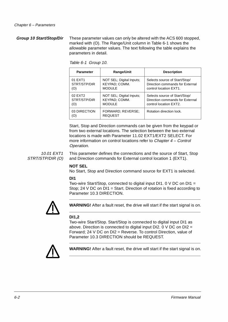
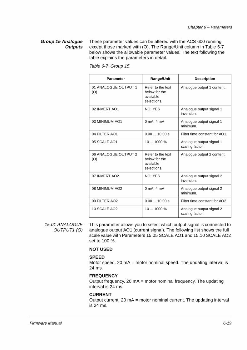
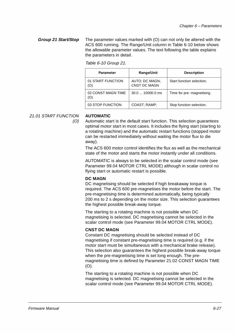
Group 10 Start/Stop/Dir These parameter values can only be altered with the ACS 600 stopped, marked with (O). The Range/Unit column in Table 6-1 shows the allowable parameter values. The text following the table explains the parameters in detail.
Table 6-1 Group 10.
Start, Stop and Direction commands can be given from the keypad or from two external locations. The selection between the two external locations is made with Parameter 11.02 EXT1/EXT2 SELECT. For more information on control locations refer to Chapter 4 – Control Operation.
10.01 EXT1STRT/STP/DIR (O)
This parameter defines the connections and the source of Start, Stop and Direction commands for External control location 1 (EXT1).
NOT SELNo Start, Stop and Direction command source for EXT1 is selected.
DI1Two-wire Start/Stop, connected to digital input DI1. 0 V DC on DI1 = Stop; 24 V DC on DI1 = Start. Direction of rotation is fixed according to Parameter 10.3 DIRECTION.
WARNING! After a fault reset, the drive will start if the start signal is on.
DI1,2Two-wire Start/Stop. Start/Stop is connected to digital input DI1 as above. Direction is connected to digital input DI2. 0 V DC on DI2 = Forward; 24 V DC on DI2 = Reverse. To control Direction, value of Parameter 10.3 DIRECTION should be REQUEST.
WARNING! After a fault reset, the drive will start if the start signal is on.
Parameter Range/Unit Description
01 EXT1STRT/STP/DIR (O)
NOT SEL; Digital Inputs; KEYPAD; COMM. MODULE
Selects source of Start/Stop/ Direction commands for External control location EXT1.
02 EXT2 STRT/STP/DIR (O)
NOT SEL; Digital Inputs; KEYPAD; COMM. MODULE
Selects source of Start/Stop/ Direction commands for External control location EXT2.
03 DIRECTION (O)
FORWARD; REVERSE; REQUEST
Rotation direction lock.
Chapter 6 – Parameters
Firmware Manual 6-3
DI1P,2PThree-wire Start/Stop. Start/Stop commands are given by means of momentary push-buttons (the P stands for “pulse”). The Start push-button is normally open, and connected to digital input DI1. The Stop push-button is normally closed, and connected to digital input DI2. Multiple Start push-buttons are connected in parallel; multiple Stop push-buttons are connected in series. Direction of rotation is fixed according to Parameter 10.03 DIRECTION.
DI1P,2P,3Three-wire Start/Stop. Start/Stop connected as with DI1P,2P. Direction is connected to digital input DI3. 0 V DC on DI3 = Forward; 24 V DC on DI3 = Reverse. To control Direction, value of Parameter 10.03 DIRECTION should be REQUEST.
DI1P,2P,3PStart Forward, Start Reverse, and Stop. Start and Direction commands are given simultaneously with two separate momentary push-buttons (the P stands for “pulse”). The Stop push-button is normally closed, and connected to digital input DI3. The Start Forward and Start Reverse push-buttons are normally open, and connected to digital inputs DI1 and DI2 respectively. Multiple Start push-buttons are connected in parallel, and multiple Stop push-buttons are connected in series. To control Direction, value of Parameter 10.03 DIRECTION should be REQUEST.
DI6Two-wire Start/Stop, connected to digital input DI6. 0 V DC on DI6 = Stop and 24 V DC on DI6 = Start. Direction of rotation is fixed according to Parameter 10.03 DIRECTION.
WARNING! After a fault reset, the drive will start if the start signal is on.
DI6,5Two-wire Start/Stop. Start/Stop is connected to digital input DI6. Direction is connected to digital input DI5. 0 V DC on DI5 = Forward and 24 V DC on DI5 = Reverse. To control Direction, value of Parameter 10.03 DIRECTION should be REQUEST.
WARNING! After a fault reset, the drive will start if the start signal is on.
KEYPADThe Start/Stop and Direction commands are given from the Control Panel keypad when External control location 1 is active. To control Direction, value of Parameter 10.03 DIRECTION should be REQUEST.
COMM. MODULEThe Start/Stop and Direction commands are given through a communication (e.g. fieldbus adapter) module.
Chapter 6 – Parameters
6-4 Firmware Manual
10.02 EXT2 STRT/STP/DIR (O)
This parameter defines the connections and the source of Start, Stop and Direction commands for External control location 2 (EXT2).
Refer to Parameter 10.01 EXT1 STRT/STP/DIR (O) above for details on these settings.
10.03 DIRECTION (O) This parameter allows you to fix the direction of rotation of the motor to FORWARD or REVERSE. If you select REQUEST, the direction is selected as defined by Parameters 10.01 EXT1 STRT/STP/DIR and 10.02 EXT2 STRT/STP/DIR or by keypad push-buttons.
Note: If PFC macro is in use and External reference 2 is the active reference of ACS 600, this parameter is fixed to value FORWARD. No other setting is accepted. The same restriction is valid in local control (i.e. Panel is the active control device) when the value of Parameter 11.01 KEYPAD REF SEL is REF2 (%). With Hand/Auto macro there is no restriction for the direction.
Chapter 6 – Parameters
Firmware Manual 6-5
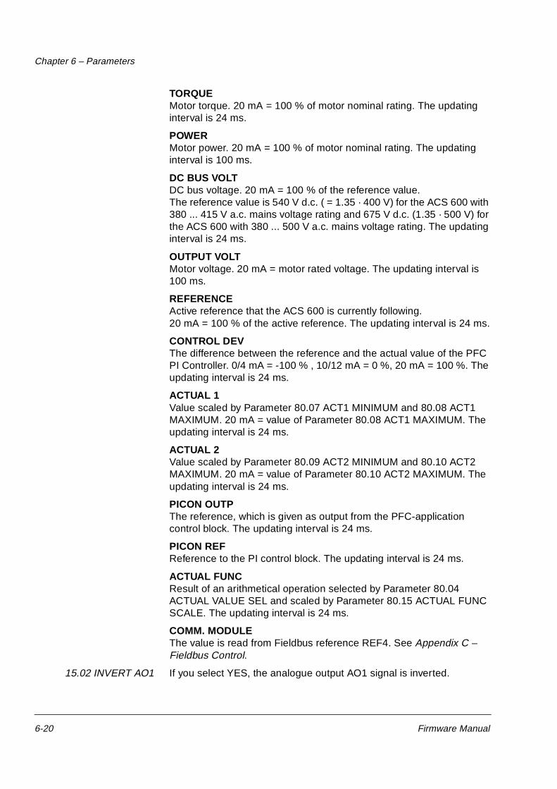
Group 11 ReferenceSelect
These parameter values can be altered with the ACS 600 running, except those marked with (O). The Range/Unit column in Table 6-2 shows the allowable parameter values. The text in the table below explains the parameters in detail.
Table 6-2 Group 11.
Reference can be set from the keypad or from two external locations. Refer to Chapter 4 – Control Operation, section Local vs. External Control.
11.01 KEYPAD REF SEL REF1 (Hz)Keypad reference 1 is selected as the active keypad reference. The type of the reference is frequency, given in Hz.
REF2 (%)Keypad reference 2 is selected as the active keypad reference. Keypad reference 2 is given in %. The type of Keypad reference 2 depends on the selected Application Macro. If PFC Macro is selected REF 2 (%) is process reference. If Hand/Auto Macro is selected REF2 (%) is a relative frequency reference.
11.02 EXT1/EXT2SELECT (O)
This parameter sets the input used for selecting the external control location, or fixes it to EXT1 or EXT2. The external control location of both Start/Stop/Direction commands and reference is determined by this parameter.
Parameter Range/Unit Description
01 KEYPAD REF SEL REF1 (Hz); REF2 (%) Selection of active keypad reference.
02 EXT1/EXT2 SELECT (O)
DI1 ... DI6; EXT1; EXT2; COMM. MODULE
External control location selection input.
03 EXT REF1 SELECT (O)
KEYPAD; Analogue Inputs; COMM. MODULE
External reference 1 input.
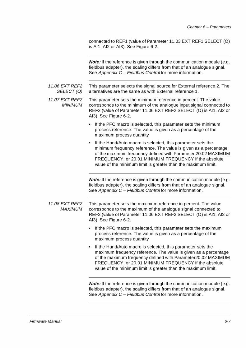
04 EXT REF1 MINIMUM
0 ... 120 Hz External reference 1 minimum value.
05 EXT REF1 MAXIMUM
0 ... 120 Hz External reference 1 maximum value.
06 EXT REF2 SELECT (O)
KEYPAD; Analogue Inputs; COMM. MODULE
External reference 2 input.
07 EXT REF2 MINIMUM
0 ... 100 % External reference 2 minimum value.
08 EXT REF2 MAXIMUM
0 ... 500 % External reference 2 maximum value.
Chapter 6 – Parameters
6-6 Firmware Manual
EXT1External control location 1 is selected. The control signal sources for EXT1 are defined with Parameter 10.1 (Start/Stop/Direction commands) and Parameter 11.3 (reference).
EXT2External control location 2 is selected. The control signal sources for EXT2 are defined with Parameter 10.2 (Start/Stop/Direction commands) and Parameter 11.6 (reference).
DI1 - DI6External control location 1 or 2 is selected according to the state of the selected digital input (DI1 ... DI6), where 0 V DC = EXT1 and 24 V DC = EXT2.
COMM. MODULEExternal control location 1 or 2 is chosen through a communication (e.g. fieldbus adapter) module.
11.03 EXT REF1SELECT (O)
This parameter selects the signal source of External reference 1.
KEYPADReference is given from the Keypad. The first line on the display shows the reference value.
AI1Reference from analogue input 1 (voltage signal).
AI2Reference from analogue input 2 (current signal).
AI3Reference from analogue input 3 (current signal).
AI1+AI3; AI2+AI3; AI1-AI3; AI2-AI3; AI1*AI3; AI2*AI3; MIN(AI1,AI3); MIN(AI2,AI3); MAX(AI1,AI3); MAX(AI2,AI3)The reference is calculated from the selected input signals according to the mathematical functions defined by this setting.
COMM. MODULEThe reference is given through a communication (e.g. fieldbus adapter) module.
11.04 EXT REF1MINIMUM
This parameter sets the minimum frequency reference in Hz. The value corresponds to the minimum of the analogue input signal connected to REF1 (value of Parameter 11.03 EXT REF1 SELECT (O) is AI1, AI2 or AI3). See Figure 6-2.
Note: If the reference is given through the communication module (e.g. fieldbus adapter), the scaling differs from that of an analogue signal. See Appendix A – Complete Parameter Settings for more information.
11.05 EXT REF1MAXIMUM
This parameter sets the maximum frequency reference in Hz. The value corresponds to the maximum of the analogue input signal
Chapter 6 – Parameters
Firmware Manual 6-7
connected to REF1 (value of Parameter 11.03 EXT REF1 SELECT (O) is AI1, AI2 or AI3). See Figure 6-2.
Note: If the reference is given through the communication module (e.g. fieldbus adapter), the scaling differs from that of an analogue signal. See Appendix C – Fieldbus Control for more information.
11.06 EXT REF2SELECT (O)
This parameter selects the signal source for External reference 2. The alternatives are the same as with External reference 1.
11.07 EXT REF2MINIMUM
This parameter sets the minimum reference in percent. The value corresponds to the minimum of the analogue input signal connected to REF2 (value of Parameter 11.06 EXT REF2 SELECT (O) is AI1, AI2 or AI3). See Figure 6-2.
• If the PFC macro is selected, this parameter sets the minimum process reference. The value is given as a percentage of the maximum process quantity.
• If the Hand/Auto macro is selected, this parameter sets the minimum frequency reference. The value is given as a percentage of the maximum frequency defined with Parameter 20.02 MAXIMUM FREQUENCY, or 20.01 MINIMUM FREQUENCY if the absolute value of the minimum limit is greater than the maximum limit.
Note: If the reference is given through the communication module (e.g. fieldbus adapter), the scaling differs from that of an analogue signal. See Appendix C – Fieldbus Control for more information.
11.08 EXT REF2MAXIMUM
This parameter sets the maximum reference in percent. The value corresponds to the maximum of the analogue signal connected to REF2 (value of Parameter 11.06 EXT REF2 SELECT (O) is AI1, AI2 or AI3). See Figure 6-2.
• If the PFC macro is selected, this parameter sets the maximum process reference. The value is given as a percentage of the maximum process quantity.
• If the Hand/Auto macro is selected, this parameter sets the maximum frequency reference. The value is given as a percentage of the maximum frequency defined with Parameter20.02 MAXIMUM FREQUENCY, or 20.01 MINIMUM FREQUENCY if the absolute value of the minimum limit is greater than the maximum limit.
Note: If the reference is given through the communication module (e.g. fieldbus adapter), the scaling differs from that of an analogue signal. See Appendix C – Fieldbus Control for more information.
Chapter 6 – Parameters
6-8 Firmware Manual
Figure 6-2 Setting EXT REF MINIMUM and MAXIMUM. The range of the analogue input signal is set by Parameter 13.02 MAXIMUM AI1, 13.07 MAXIMUM AI2, 13.12 MAXIMUM AI3 and Parameter 13.01 MINIMUM AI1, 13.06 MINIMUM AI2, 13.11 MINIMUM AI3, depending on the analogue input used. EXT REF2 is a frequency reference of the motor, or a process reference depending on the selected Application Macro.
10 V20 mA
0/2 V0/4 mA
The range of analogue
input
MAXIMUM AI
MINIMUM AI
120 Hz
52 Hz
0 Hz
120 Hz
0 Hz
11.05 EXT REF1 MAXIMUM
11.04 EXT REF1 MINIMUM
500 %
100 %
0 %
100 %
0 %
11.08 EXT REF2 MAXIMUM
11.07 EXT REF2 MINIMUM
The range of exter-nal reference 1
The range of exter-nal reference 2
Chapter 6 – Parameters
Firmware Manual 6-9
Group 12 Constant Freq These parameter values can be altered with the ACS 600 running, except those marked with (O). The Range/Unit column in Table 6-3 below shows the allowable parameter values. The text following the table explains the parameters in detail.
Table 6-3 Group 12.
Constant frequencies override any other references.
Note: If PFC Macro is in use and Parameter 12.01 CONST FREQ SEL (O) is set to a value other than NOT SEL and one of the selected Digital input is set to high level, the automatic Pump and Fan Control (PFC) is bypassed: No process PI controller is in use and the constant speed motors are not started.
12.01 CONST FREQ SEL(O)
This parameter defines which digital inputs are used to select Constant Frequencies.
NOT SELConstant frequency function disabled.
DI4 (FREQ1); DI5 (FREQ2)Constant frequency 1 to 2 is selected with digital input. 24 V d.c. = constant frequency is activated.
DI4,5Three constant frequencies (1 ... 3) are selected with two digital inputs according to Table 6-4 below.
Table 6-4 Constant frequency selection with digital inputs DI4,5.
Parameter Range/Unit Description
01 CONST FREQ SEL (O) NOT SEL; Digital inputs Const. freq. selection
02 CONST FREQ 1 0 ... 120 Hz Constant frequency 1
03 CONST FREQ 2 0 ... 120 Hz Constant frequency 2
04 CONST FREQ 3 0 ... 120 Hz Constant frequency 3
DI4 DI5 Function
0 0 No constant frequency
1 0 Constant Frequency 1
0 1 Constant Frequency 2
1 1 Constant Frequency 3
Chapter 6 – Parameters
6-10 Firmware Manual
12.02 CONST FREQ 1 Programmable constant frequencies ranging from 0 to 120 Hz.
12.03 CONST FREQ 2 Programmable constant frequencies ranging from 0 to 120 Hz.
12.04 CONST FREQ 3 Programmable constant frequencies ranging from 0 to 120 Hz.
Chapter 6 – Parameters
Firmware Manual 6-11
Group 13 AnalogueInputs
These parameter values can be altered with the ACS 600 running. The Range/Unit column in Table 6-5 below shows the allowable parameter values. The text following the table explains the parameters in detail.
Table 6-5 Group 13.
Parameter Range/Unit Description
1 MINIMUM AI1 0 V; 2 V; TUNED VALUE; TUNE
Minimum value of AI1. Value to correspond to minimum reference.
2 MAXIMUM AI1 10 V; TUNED VALUE; TUNE
Maximum value of AI1. Value to correspond to maximum reference.
3 SCALE AI1 0 ... 100.0 % Scaling factor for AI1.
4 FILTER AI1 0 ... 10 s Filter time constant for AI1.
5 INVERT AI1 NO; YES Analogue input signal 1 inversion.
6 MINIMUM AI2 0 mA; 4 mA; TUNED VALUE; TUNE
Minimum value of AI2. Value to correspond to minimum reference.
7 MAXIMUM AI2 20 mA; TUNED VALUE; TUNE
Maximum value of AI2. Value to correspond to maximum reference.
8 SCALE AI2 0 ... 100.0 % Scaling factor for AI2.
9 FILTER AI2 0 ... 10 s Filter time constant for AI2.
10 INVERT AI2 NO; YES Analogue input signal 2 inversion.
11 MINIMUM AI3 0 mA; 4 mA; TUNED VALUE; TUNE
Minimum value of AI3. Value to correspond to minimum reference.
12 MAXIMUM AI3 20 mA; TUNED VALUE; TUNE
Maximum value of AI3. Value to correspond to maximum reference.
14 FILTER AI3 0 ... 10 s Filter time constant for AI3.
15 INVERT AI3 NO; YES Analogue input signal 3 inversion.
Chapter 6 – Parameters
6-12 Firmware Manual
13.01 MINIMUM AI1 0 V; 2 V; TUNED VALUE; TUNE
This parameter sets the minimum value of the signal to be applied to AI1. If AI1 is selected as the signal source for external reference 1 (Par. 11.03 EXT REF1 SELECT (O)) or external reference 2 (Par. 11.06 EXT REF2 SELECT (O)), this value will correspond to the reference defined by Parameter 11.04 EXT REF1 MINIMUM or 11.07 EXT REF2 MINIMUM. Typical minimum values are 0 V or 2 V.
To tune the minimum value according to the analogue input signal, press the ENTER key, select TUNE, apply the minimum analogue input signal and press ENTER again. The value is set as the minimum. The readable range in tuning is 0 V to 10 V. The text TUNED VALUE is displayed after the TUNE operation.
The ACS 600 has a “living zero” function which allows the protection and supervision circuitry to detect a loss of control signal. To enable this feature, the minimum input signal must be set higher than 0.5 V and Parameter 30.01 AI<MIN FUNCTION must be set accordingly.
13.02 MAXIMUM AI1 10 V; TUNED VALUE; TUNE
This parameter sets the maximum value of the signal to be applied to AI1. If AI1 is selected as the signal source for external reference 1 (Par. 11.03 EXT REF1 SELECT (O)) or external reference 2 (Par. 11.06 EXT REF2 SELECT (O)), this value will correspond to the reference defined by Parameter 11.05 EXT REF1 MAXIMUM or 11.08 EXT REF2 MAXIMUM. A typical maximum value is 10 V.
To tune the maximum value according to the analogue input signal, press the ENTER key, select TUNE, apply the maximum analogue input signal and press ENTER again. The value is set as the maximum. The readable range in tuning is 0 V to 10 V. The text TUNED VALUE is displayed after TUNE operation.
13.03 SCALE AI1 Scaling factor for analogue input AI1 signal. See Figure 6-4.
13.04 FILTER AI1 Filter time constant for analogue input AI1. As the analogue input value changes, 63 % of the change takes place within the time specified by this parameter.
Note: Even if you select 0 s as the minimum value, the signal is still filtered with a time constant of 10 ms due to the signal interface hardware. This cannot be changed by any parameters.
Chapter 6 – Parameters
Firmware Manual 6-13
Figure 6-3 Filter time constant for analogue input AI1.
13.05 INVERT AI1 NO;YES
If this parameter is set to YES, the maximum value of the analogue input signal corresponds to minimum reference and the minimum value of the analogue input signal corresponds to maximum reference.
13.06 MINIMUM AI2 0 mA; 4 mA; TUNED VALUE; TUNE
This parameter sets the minimum value of the signal to be applied to analogue input AI2. If AI2 is selected as the signal source for external reference 1 (Par. 11.03 EXT REF1 SELECT (O)) or external reference 2 (Par. 11.06 EXT REF2 SELECT (O)), this value will correspond to the reference set by Parameter 11.04 EXT REF1 MINIMUM or 11.07 EXT REF2 MINIMUM. Typical minimum values are 0 mA or 4 mA.
To tune the minimum value according to the analogue input signal, press the ENTER key, select TUNE, apply the minimum analogue input signal and press ENTER again. The value is set as the minimum. The readable range in tuning is 0 mA to 20 mA. The text TUNED VALUE is displayed after the TUNE operation.
The ACS 600 has a “living zero” function which allows the protection and supervision circuitry to detect a loss of signal. To enable this feature, the minimum input signal must be greater than 1 mA.
13.07 MAXIMUM AI2 20 mA; TUNED VALUE; TUNE
This parameter sets the maximum value of the signal to be applied to AI2. If AI2 is selected as the signal source for external reference 1 (Parameter 11.03 EXT REF1 SELECT (O)) or external reference 2 (Parameter 11.06 EXT REF2 SELECT (O)), this value will correspond to the reference defined by Parameter 11.05 EXT REF1 MAXIMUM or 11.08 EXT REF2 MAXIMUM. A typical maximum value is 20 mA.
To tune the maximum value according to the analogue input signal, press the ENTER key, select TUNE, apply the maximum analogue input signal and press ENTER again. The values is set as the
63
[%]
100
Time constantt
Filtered Signal
Unfiltered Signal
Chapter 6 – Parameters
6-14 Firmware Manual
maximum. The readable range in tuning is 0 mA to 20 mA. The text TUNED VALUE is displayed after TUNE operation.
13.08 SCALE AI2 Refer to Parameter 13.03 SCALE AI1.
13.09 FILTER AI2 Refer to Parameter 13.04 FILTER AI1.
13.10 INVERT AI2 Refer to Parameter 13.05 INVERT AI1.
13.11 MINIMUM AI3 Refer to Parameter 13.06 MINIMUM AI2.
13.12 MAXIMUM AI3 Refer to Parameter 13.07 MAXIMUM AI2.
13.13 SCALE AI3 Refer to Parameter 13.03 SCALE AI1.
13.14 FILTER AI3 Refer to Parameter 13.04 FILTER AI1.
13.15 INVERT AI3 Refer to Parameter 13.05 INVERT AI1.
Figure 6-4 Example of scaling of analogue inputs. External reference 1 has been selected by Parameter 11.03 EXT REF1 SELECT (O) as AI1 + AI3 and the maximum value for it (120 Hz) by Parameter 11.05 EXT REF1 MAXIMUM. The scale for analogue input AI1 is set to 100 % by Parameter 13.03 SCALE AI1. The scale for analogue input AI3 is set to 10 % by Parameter 13.13 SCALE AI3.
60 %
40 %
12 Hz120 Hz10 V
SCALE AI1100 %
SCALE AI310 %
0 V 0 mA
20 mA EXT REF1 MAXIMUM120 Hz
EXT REF1
48 Hz55.2 Hz
AI1 + AI3 =
0 Hz
7.2 Hz
Chapter 6 – Parameters
Firmware Manual 6-15
Group 14 Relay Outputs These parameter values can only be altered when the ACS 600 is stopped, marked with (O). The text following Table 6-6 below explains the parameters in detail.
Table 6-6 Group 14
14.01 RELAY RO1OUTPUT (O)
This parameter allows you to select which information is indicated with relay output 1.
M1 STARTShould be selected only if Pump and Fan Control (PFC) macro is active. Relay is energised when automatic Pump and Fan Control (PFC) switches on motor no. 1. Relay is de-energised when PFC switches off motor no. 1.
Note: Parameter has always the value M1 START if either of the following conditions is valid:
• In external control: External reference 2 is active and Parameter 81.18 AUTOCHANGE INTERVAL is greater than zero.
• In local control: Parameter 11.01 KEYPAD REF SEL is REF2 (%) and Parameter 81.18 AUTOCHANGE INTERVAL is greater than zero.
NOT USED
READYThe ACS 600 is ready to function. The relay is energized unless no Run enable signal is present or a fault exists.
RUNNINGThe ACS 600 has been started, Run enable signal is active, and no active faults exist.
FAULTA fault has occurred. Refer to Chapter 7 – Fault Tracing for more details.
Parameter Range/Unit Description
01 RELAY RO1 OUTPUT (O)
Refer to the text below for the available selections.
Relay output 1 content.
02 RELAY RO2 OUTPUT (O)
Relay output 2 content.
03 RELAY RO3 OUTPUT (O)
Relay output 3 content.
04 EXT 2 REL OUTPUT1 (O)
Extension module 2 relay output 1
05 EXT 2 REL OUTPUT2 (O)
Extension module 2 relay output 2
Chapter 6 – Parameters
6-16 Firmware Manual
FAULT (-1)Relay energized when power is applied, and de-energized upon a fault trip.
FAULT(RST)The ACS 600 is in a fault condition, but will reset after the programmed autoreset delay (refer to Parameter 31.03 DELAY TIME).
STALL WARNStall alarm has been activated (refer to Parameter 30.10 STALL FUNCTION).
STALL FLTStall protection has tripped (refer to Parameter 30.10 STALL FUNCTION).
MOT TEMP WRNMotor temperature has exceeded the warning level.
MOT TEMP FLTMotor thermal protection has tripped.
ACS TEMP WRNThe ACS 600 temperature has exceeded the warning level 115 °C(239 °F).
ACS TEMP FLTThe ACS 600 overheat protection has tripped. The tripping level is 125 °C (257 °F).
FAULT/WARNAny fault or warning has occurred.
WARNINGAny warning has occurred.
REVERSEDMotor rotates in reverse direction.
EXT CTRLExternal control is selected.
REF2 SELReference 2 is selected.
DC OVERVOLTThe intermediate circuit DC voltage has exceeded the overvoltage limit.
DC UNDERVOLThe intermediate circuit DC voltage has fallen below the undervoltage limit.
FREQ 1 LIMOutput speed has exceeded or fallen below the supervision limit 1. Refer to Parameter 32.01 FREQ 1 FUNCTION and Parameter 32.02 FREQ 1 LIMIT.
Chapter 6 – Parameters
Firmware Manual 6-17
FREQ 2 LIMOutput speed has exceeded or fallen below the supervision limit 2. Refer to Parameter 32.03 FREQ 2 FUNCTION and Parameter 32.04 FREQ 2 LIMIT.
CURRENT LIMMotor current has exceeded or fallen below the set current supervision limit. Refer to Parameter 32.05 CURRENT FUNCTION and Parameter 32.06 CURRENT LIMIT.
REF 1 LIMReference 1 has exceeded or fallen below the set supervision limit. Refer to Parameter 32.07 REF1 FUNCTION and Parameter 32.08 REF1 LIMIT.
REF 2 LIMReference 2 has exceeded or fallen below the set supervision limit. Refer to Parameter 32.09 EF2 FUNCTION and Parameter 32.10 REF2 LIMIT.
STARTEDThe ACS 600 has received a Start command.
LOSS OF REFThe reference has been lost.
AT SPEEDThe actual value has reached the reference value. The speed error is max. 10 % of the nominal speed in the speed control mode.
ACT 1 LIMActual value 1 has exceeded or fallen below the set supervision limit. Refer to Parameter 32.11 ACT1 FUNCTION and 32.12 ACT1 LIMIT.
ACT 2 LIMActual value 2 has exceeded or fallen below the set supervision limit. Refer to Parameter 32.13 ACT2 FUNCTION and 32.14 ACT2 LIMIT.
COMM. MODULEThe relay is controlled by Fieldbus reference REF3.See Appendix C – Fieldbus Control.
14.02 RELAY RO2OUTPUT (O)
Refer to Parameter 14.01 RELAY RO1 OUTPUT (O). Exception: Selection M1 START is replaced with M2 START.
M2 STARTShould be selected only if Pump and Fan Control (PFC) macro is active. Relay is energised when automatic Pump and Fan Control (PFC) switches on motor no. 2. Relay is de-energised when PFC switches off motor no. 2.
Note: Parameter has always the value M2 START if either one of the following conditions is valid:
• In external control: External reference 2 is active, parameter
Chapter 6 – Parameters
6-18 Firmware Manual
81.18 AUTOCHANGE INTERVAL is greater than zero and Parameter 81.17 NBR OF AUX MOTORS (O) is greater or equal than 1.
• In local control: Parameter 11.01 KEYPAD REF SEL is REF2 (%), parameter 81.18 AUTOCHANGE INTERVAL is greater than zero and Parameter 81.17 NBR OF AUX MOTORS (O) is greater or equal than 1.
14.03 RELAY RO3OUTPUT (O)
Refer to Parameter 14.01 RELAY RO1 OUTPUT (O). Exceptions: Selection M1 START is replaced with M3 START, ACT1 LIM with MAGN READY and ACT2 LIM with USER 2 SEL
M3 STARTShould be selected only if Pump and Fan Control (PFC) macro is active. Relay is energised when automatic Pump and Fan Control (PFC) switches on motor no. 3. Relay is de-energised when PFC switches off motor no. 3.
Note: Parameter has always the value M3 START if either one of the following conditions is valid:
• In external control: External reference 2 is active, parameter 81.18 AUTOCHANGE INTERVAL is greater than zero and Parameter 81.17 NBR OF AUX MOTORS (O) is greater or equal than 2.
• In local control: Parameter 11.01 KEYPAD REF SEL is REF2 (%), parameter 81.18 AUTOCHANGE INTERVAL is greater than zero and Parameter 81.17 NBR OF AUX MOTORS (O) is greater or equal than 2.
MAGN READYThe motor is magnetised and ready to give nominal torque (nominal magnetising of the motor has been reached).
USER 2 SELThe User Macro 2 has been loaded.
14.04 EXT 2 RELOUTPUT 1 (O)
This parameter allows you to select which information is indicated with extension module 2 relay output 1.
Refer to Parameter 14.01 RELAY RO1 OUTPUT (O) for details on these selections.
Chapter 6 – Parameters
Firmware Manual 6-19
Group 15 AnalogueOutputs
These parameter values can be altered with the ACS 600 running, except those marked with (O). The Range/Unit column in Table 6-7 below shows the allowable parameter values. The text following the table explains the parameters in detail.
Table 6-7 Group 15.
15.01 ANALOGUEOUTPUT1 (O)
This parameter allows you to select which output signal is connected to analogue output AO1 (current signal). The following list shows the full scale value with Parameters 15.05 SCALE AO1 and 15.10 SCALE AO2 set to 100 %.
NOT USED
SPEEDMotor speed. 20 mA = motor nominal speed. The updating interval is 24 ms.
FREQUENCYOutput frequency. 20 mA = motor nominal frequency. The updating interval is 24 ms.
CURRENTOutput current. 20 mA = motor nominal current. The updating interval is 24 ms.
Parameter Range/Unit Description
01 ANALOGUE OUTPUT 1 (O)
Refer to the text below for the available selections.
Analogue output 1 content.
02 INVERT AO1 NO; YES Analogue output signal 1 inversion.
03 MINIMUM AO1 0 mA; 4 mA Analogue output signal 1 minimum.
04 FILTER AO1 0.00 ... 10.00 s Filter time constant for AO1.
TORQUEMotor torque. 20 mA = 100 % of motor nominal rating. The updating interval is 24 ms.
POWERMotor power. 20 mA = 100 % of motor nominal rating. The updating interval is 100 ms.
DC BUS VOLTDC bus voltage. 20 mA = 100 % of the reference value. The reference value is 540 V d.c. ( = 1.35 · 400 V) for the ACS 600 with 380 ... 415 V a.c. mains voltage rating and 675 V d.c. (1.35 · 500 V) for the ACS 600 with 380 ... 500 V a.c. mains voltage rating. The updating interval is 24 ms.
OUTPUT VOLTMotor voltage. 20 mA = motor rated voltage. The updating interval is 100 ms.
REFERENCEActive reference that the ACS 600 is currently following. 20 mA = 100 % of the active reference. The updating interval is 24 ms.
CONTROL DEVThe difference between the reference and the actual value of the PFC PI Controller. 0/4 mA = -100 % , 10/12 mA = 0 %, 20 mA = 100 %. The updating interval is 24 ms.
ACTUAL 1Value scaled by Parameter 80.07 ACT1 MINIMUM and 80.08 ACT1 MAXIMUM. 20 mA = value of Parameter 80.08 ACT1 MAXIMUM. The updating interval is 24 ms.
ACTUAL 2Value scaled by Parameter 80.09 ACT2 MINIMUM and 80.10 ACT2 MAXIMUM. 20 mA = value of Parameter 80.10 ACT2 MAXIMUM. The updating interval is 24 ms.
PICON OUTPThe reference, which is given as output from the PFC-application control block. The updating interval is 24 ms.
PICON REFReference to the PI control block. The updating interval is 24 ms.
ACTUAL FUNCResult of an arithmetical operation selected by Parameter 80.04 ACTUAL VALUE SEL and scaled by Parameter 80.15 ACTUAL FUNC SCALE. The updating interval is 24 ms.
COMM. MODULEThe value is read from Fieldbus reference REF4. See Appendix C – Fieldbus Control.
15.02 INVERT AO1 If you select YES, the analogue output AO1 signal is inverted.
Chapter 6 – Parameters
Firmware Manual 6-21
15.03 MINIMUM AO1 The minimum value of the analogue output signal can be set to either 0 mA or 4 mA.
15.04 FILTER AO1 Filter time constant for analogue output AO1.
As the analogue output value changes, 63 % of the change takes place within the time period specified by this parameter (See Figure 6-3).
Note: Even if you select 0 s as the minimum value, the signal is still filtered with a time constant of 10 ms due to the signal interface hardware. This cannot be changed by any parameters.
15.05 SCALE AO1 This parameter is the scaling factor for the analogue output AO1 signal. If the selected value is 100 %, the nominal value of the output signal corresponds to 20 mA. If the maximum is less than full scale, increase the value of this parameter.
Example: The nominal motor current is 7.5 A and the measured maximum current at maximum load is 5 A. The motor current 0 to 5 A is read as 0 to 20 mA analogue signal through AO1.
1. AO1 is set to CURRENT with Parameter 15.1.
2. AO1 minimum is set to 0 mA with Parameter 15.3.
3. The measured maximum motor current is scaled to correspond to 20 mA analogue output signal: The reference value of the output signal CURRENT is the motor nominal current i.e. 7.5 A (see Parameter 15.1). With 100 % scaling, the reference value corresponds to full scale output signal 20 mA. To make the measured maximum motor current correspond to 20 mA, it should be scaled equal to the reference value before it is converted to analogue output signal.
Thus the scaling factor is set to 150 %.
15.06 ANALOGUEOUTPUT2 (O)
Refer to Parameter 15.1.
15.07 INVERT AO2 Refer to Parameter 15.2.
15.08 MINIMUM AO2 Refer to Parameter 15.3.
15.09 FILTER AO2 Refer to Parameter 15.4.
15.10 SCALE AO2 Refer to Parameter 15.5.
k · 5 A = 7.5 A => k = 1.5 = 150 %
Chapter 6 – Parameters
6-22 Firmware Manual
Group 16 System CtrInputs
These parameter values can only be altered with the ACS 600 stopped, marked with (O). The Range/Unit column in Table 6-8 below shows the allowable parameter values. The text following the table explains the parameters in detail.
Table 6-8 Group 16.
16.01 RUN ENABLE (O) This parameter selects the source of the run enable signal.
Indication of missing Run Enable signal is shown on the first row of the Control Panel display (see Chapter 2 – Overview of ACS 600 Programming and the CDP 312 Control Panel).
YESRun enable signal is active. The ACS 600 is ready to start without an external run enable signal.
DI1 ... DI6To activate the Run Enable signal, the selected digital input must be connected to +24 V DC. If the voltage drops to 0 V DC, the ACS 600 will coast to stop and will not start until the Run enable signal resumes.
COMM. MODULEThe signal is given through a communication (e.g. fieldbus adapter) module. See Appendix C – Fieldbus Control.
16.02 PARAMETERLOCK (O)
This parameter selects the state of the Parameter Lock. With Parameter Lock you can inhibit unauthorised parameter changes.
OPENParameter Lock is open. Parameters can be altered.
LOCKEDParameter Lock is closed from the Control Panel. Parameters cannot be altered. The Parameter Lock can be opened only by entering the valid code at Parameter 16.03 PASS CODE (O).
04 FAULT RESET SEL (O) NOT SEL; DI1 ... DI6; ON STOP; COMM. MODULE
Fault reset input.
05 USER MACRO IO CHG (O)
NOT SEL; DI1 ... DI6 Restores parameters to user macro setting values.
06 LOCAL LOCK (O) OFF; ON Disables local control (Panel)
07 PARAM SAVE (O) SAVE..; DONE Parameter saving to the permanent memory
Chapter 6 – Parameters
Firmware Manual 6-23
16.03 PASS CODE (O) This parameter selects the Pass Code for the Parameter Lock. The default value of this parameter is 0. In order to open the Parameter Lock change the value to 358. After the Parameter Lock is opened the value is automatically changed back to 0.
16.04 FAULT RESET SEL(O)
NOT SEL; DI1 ... DI6If you select NOT SEL, fault reset is executed from the Control Panel keypad. If a digital input is selected, fault reset is executed from an external switch or from the Control Panel. Reset is activated by opening a normally closed contact (negative edge on digital input).
ON STOPFault reset is executed along with the stop signal.
COMM. MODULEThe signal is given through a communication (e.g. fieldbus adapter) module. See Appendix C – Fieldbus Control.
16.05 USER MACRO IOCHG (O)
NOT SEL; DI1 ... DI6
This parameter enables the selection of the desired User Macro via a digital input in the following way:
When the state of the specified digital input changes from high to low User Macro 1 is loaded. When the state of the specified digital input changes from low to high User Macro 2 is loaded.
The User Macro used can be changed via a digital input only when the drive is stopped. During the change of the Macro the drive will not start.
The value of this parameter is not included in the User Macro. The setting once made remains despite of the User Macro change.
User Macro 2 selection can be supervised via relay output 3. See Parameter 14.03 RELAY RO3 OUTPUT (O) for more information.
Note: Always redo the User Macro save by Parameter 99.02 APPLICATION MACRO after changing parameter settings or reperforming the motor identification. If Parameter 16.05 USER MACRO IO CHG (O) is pointing to digital input, the last settings saved by the user are loaded into use whenever the power is switched off and on again, or macro is changed. Any unsaved changes will be lost.
16.06 LOCAL LOCK (O) OFF; ONSelection ON disables local control (Panel) after which the control signals (Start, Stop, Direction, Reference) cannot be given from panel.
LOC/REM key of the Control Panel cannot be used for restoring the local control while ON is selected.
WARNING: Before activating this function it must be ensured that the Control Panel is not needed for stopping the drive.
Chapter 6 – Parameters
6-24 Firmware Manual
16.07 PARAM SAVE (O) SAVE..; DONESelection SAVE saves parameter values to the permanent memory.
Note: A new parameter value of a standard macro is saved automatically when changed from the Panel but not when altered through a fieldbus connection.
Chapter 6 – Parameters
Firmware Manual 6-25
Group 20 Limits These parameter values can be altered with the ACS 600 running. The Range/Unit column in Table 6-9 below shows the allowable parameter values. The text following the table explains the parameters in detail.
Table 6-9 Group 20.
20.01 MINIMUMFREQUENCY
Represents the minimum frequency. The default value depends on the selected motor. When the value is positive the motor will not run in the reverse direction. With PFC macro negative values must not be used.
20.02 MAXIMUMFREQUENCY
Represents the maximum frequency. The default value depends on the selected motor. With PFC macro negative values must not be used.
20.03 MAXIMUMCURRENT
The maximum output current that the ACS 600 will supply to the motor. The default value is 200 % Ihd e.g. 200 percentage of the heavy-duty use output current of the ACS 600.
20.04 MAXIMUMTORQUE
This setting defines the momentarily allowed maximum torque of the motor. The motor control software of the ACS 600 limits the setting range of the maximum torque according to the inverter and motor data. The default value is 300 % of the nominal torque of the motor.
This limit cannot be set in the SCALAR control mode.
20.05 OVERVOLTAGECTRL
Selection OFF deactivates the overvoltage controller.
Fast braking of a high inertia load causes the DC bus voltage to rise to the overvoltage control limit. To prevent the DC voltage from exceeding the limit, the overvoltage controller automatically decreases the braking torque.
CAUTION! If a braking chopper and a braking resistor are connected to the ACS 600, this parameter value must be set to OFF to ensure proper operation of the chopper.
20.06 UNDERVOLTAGECTRL
Selection OFF deactivates the undervoltage controller.
If the DC bus voltage drops due to loss of input power, the
02 MAXIMUM FREQ -120.00 ... 120.00 Hz Operating range maximum frequency
03 MAXIMUM CURRENT 0 % Ihd...200 % Ihd Maximum output current.
04 MAXIMUM TORQUE 0 % ... 300 % Maximum output torque. Cannot be used in the SCALAR mode.
05 OVERVOLTAGE CTRL ON; OFF DC overvoltage controller
06 UNDERVOLTAGE CTRL
ON; OFF DC undervoltage controller
Chapter 6 – Parameters
6-26 Firmware Manual
undervoltage controller will decrease the motor speed in order to keep the DC bus voltage above the lower limit. By decreasing the motor speed, the inertia of the load will cause regeneration back into the ACS 600, keeping the DC bus charged, and preventing an undervoltage trip. This will increase power loss ride through on systems with a high inertia, such as a centrifuge or fan.
Chapter 6 – Parameters
Firmware Manual 6-27
Group 21 Start/Stop The parameter values marked with (O) can not only be altered with the ACS 600 running. The Range/Unit column in Table 6-10 below shows the allowable parameter values. The text following the table explains the parameters in detail.
Table 6-10 Group 21.
21.01 START FUNCTION(O)
AUTOMATICAutomatic start is the default start function. This selection guarantees optimal motor start in most cases. It includes the flying start (starting to a rotating machine) and the automatic restart functions (stopped motor can be restarted immediately without waiting the motor flux to die away).
The ACS 600 motor control identifies the flux as well as the mechanical state of the motor and starts the motor instantly under all conditions.
AUTOMATIC is always to be selected in the scalar control mode (see Parameter 99.04 MOTOR CTRL MODE) although in scalar control no flying start or automatic restart is possible.
DC MAGNDC magnetising should be selected if high breakaway torque is required. The ACS 600 pre-magnetises the motor before the start. The pre-magnetising time is determined automatically, being typically 200 ms to 2 s depending on the motor size. This selection guarantees the highest possible break-away torque.
The starting to a rotating machine is not possible when DC magnetising is selected. DC magnetising cannot be selected in the scalar control mode (see Parameter 99.04 MOTOR CTRL MODE).
CNST DC MAGNConstant DC magnetising should be selected instead of DC magnetising if constant pre-magnetising time is required (e.g. if the motor start must be simultaneous with a mechanical brake release). This selection also guarantees the highest possible break-away torque when the pre-magnetising time is set long enough. The pre-magnetising time is defined by Parameter 21.02 CONST MAGN TIME (O).
The starting to a rotating machine is not possible when DC magnetising is selected. DC magnetising cannot be selected in the scalar control mode (see Parameter 99.04 MOTOR CTRL MODE).
Parameter Range/Unit Description
01 START FUNCTION (O)
AUTO; DC MAGN; CNST DC MAGN
Start function selection.
02 CONST MAGN TIME (O)
30.0 ... 10000.0 ms Time for pre–magnetising.
03 STOP FUNCTION COAST; RAMP; Stop function selection.
Chapter 6 – Parameters
6-28 Firmware Manual
21.02 CONST MAGNTIME (O)
Defines the magnetising time in the constant magnetising mode (see parameter 21.01 START FUNCTION (O)).
21.03 STOP FUNCTION COASTThe ACS 600 stops supplying voltage immediately after a Stop command is received and the motor coasts to a stop.
RAMPRamp deceleration, as defined by the active deceleration time, Parameter 22.03 DECEL TIME 1 or Parameter 22.05 DECEL TIME 2. Motor voltage is gradually decreased to zero.
WARNING: If the Autocange function of the PFC macro is used, Parameter 21.03 STOP FUNCTION must be set to COAST (see Parameter 81.18 AUTOCHANGE INTERVAL).
Chapter 6 – Parameters
Firmware Manual 6-29
Group 22 Accel/Decel These parameter values can be altered with the ACS 600 running, except those marked with (O). The Range/Unit column in Table 6-11 below shows the allowable parameter values. The text following the table explains the parameters in detail.
Table 6-11 Group 22.
22.01 ACC/DEC 1/2 SEL(O)
This parameter selects the Acceleration/Deceleration Ramp pair that is used. The selection can be performed through digital inputs DI1 to DI6. 0 V DC = Acceleration ramp 1 and Deceleration ramp 1 are used; 24 V DC = Acceleration ramp 2 and Deceleration ramp 2 are used.
22.02 ACCEL TIME 1 The time required for the frequency to change from 0 to the maximum frequency. The maximum frequency is defined with Parameter 20.02 MAXIMUM FREQUENCY, or 20.01 MINIMUM FREQUENCY if the absolute value of the minimum limit is greater than the maximum limit.
If the reference signal changes at a rate slower than the acceleration time, the motor frequency will follow the reference signal. If the reference signal changes faster than the acceleration time, the rate at which the motor speeds up will be limited by this parameter.
If acceleration time is set too short, the ACS 600 will automatically prolong the acceleration not to exceed the maximum current limit (Parameter 20.03 MAXIMUM CURRENT).
22.03 DECEL TIME 1 The time required for the frequency to change from maximum to zero. The maximum frequency is defined with Parameter 20.02 MAXIMUM FREQUENCY, or 20.01 MINIMUM FREQUENCY, if the absolute value of the minimum limit is greater than the maximum limit.
If the reference signal changes at a rate slower than the deceleration time, the motor frequency will follow the reference signal. If the
Time for 0 frequency to max. frequency (Acceleration ramp 1).
03 DECEL TIME 1 0.00 ... 1800.00 s
Time for max. frequency to 0 frequency (Deceleration ramp 1).
04 ACCEL TIME 2 0.00 ... 1800.00 s
Time for 0 frequency to max. frequency (Acceleration ramp 2).
05 DECEL TIME 2 0.00 ... 1800.00 s
Time for max frequency to 0 frequency (Deceleration ramp 2).
06 ACC/DEC RAMP SHPE
0 ... 1000.00 s Accel./Decel. ramp shape time.
07 EM STOP RAMP TIME 0.00 ... 2000.00 s
Emergency Stop decel.ramp time.
Chapter 6 – Parameters
6-30 Firmware Manual
reference signal changes faster than the deceleration time, the rate at which the motor slows down will be limited by this parameter.
If deceleration time is set too short, the ACS 600 will automatically prolong the deceleration not to exceed the DC bus overvoltage limit. If there is any doubt about the deceleration time being too short, ensure that the DC overvoltage control is on (Parameter 20.05 OVERVOLTAGE CTRL).
If short deceleration time is needed for the high inertia application, the ACS 600 should be equipped with a braking chopper and a braking resistor. The excess energy generated during the braking is led by the chopper to the resistor and dissipated to prevent a DC voltage rise in the intermediate circuit. The chopper and the resistor are available for all ACS 600 types as optional add-on kits.
22.04 ACCEL TIME 2 Refer to Parameter 22.02 ACCEL TIME 1.
22.05 DECEL TIME 2 Refer to Parameter 22.03 DECEL TIME 1.
22.06 ACC/DECRAMP SHPE
This parameter allows you to select the shape of the acceleration/deceleration ramp.
0 sLinear ramp. Suitable for drives requiring steady acceleration or deceleration and for slow ramps.
0.100 ... 1000.00 sS-curve ramp. S-curve ramps are ideal for conveyors carrying fragile loads, or other applications where a smooth transition is required when changing from one speed to another. The S curve consists of symmetrical curves at both ends of the ramp and a linear part in between.
Chapter 6 – Parameters
Firmware Manual 6-31
Figure 6-5 Acceleration and deceleration ramp shapes.
22.07 EM STOPRAMP TIME
This parameter defines the time inside which the drive is stopped upon an Emergency Stop command. The command can be given through a communication (e.g. fieldbus adapter) module (optional).
0.00 ... 2000.00 s
WARNING: If the Autochange function of the PFC Macro is used, a Ramp stop is not allowed (see parameters 21.03 STOP FUNCTION and 81.18 AUTOCHANGE INTERVAL).
Linear ramp ACC/DEC RAMP SHPE = 0 s
S-curve ramp ACC/DEC RAMP SHPE = x s
x s
As a rule of thumb, a suitable relation between the ramp shape time and the acceleration ramp time is 1/5. Examples are given below.
Acc/Dec Ramp Time
(Par. 22.02 to 05)
Ramp Shape Time (Par. 22.06)
1 s 0.2 s
5 s 1 s
15 s 3 s
Chapter 6 – Parameters
6-32 Firmware Manual
Group 23 Speed Ctrl These parameter values can be altered with the ACS 600 running. The Range/Unit column in Table 6-12 below shows the allowable parameter values. The text following the table explains the parameters in detail.
These parameters are not visible in the SCALAR control mode.
Table 6-12 Group 23.
It is possible to tune the PI algorithm based speed controller of the ACS 600 by setting Parameters 23.01 GAIN to 23.03 SLIP GAIN in this group. The Motor ID Run automatically tunes the speed controller so it is not necessary to tune it separately.
The values of these parameters define how the output of the Speed Controller changes when there is a difference (error value) between the actual speed and the reference. Figure 6-6 displays typical step responses of the Speed Controller.
Step responses can be seen by monitoring Actual Signal 2 SPEED.
Note: The Standard Motor ID Run (refer to Chapter 3 – Start-up Data) updates the values of Parameters 23.01 GAIN and 23.02 INTEGRATION TIME.
The dynamic performance of the speed control at low speeds can be improved by increasing the relative gain and decreasing the integration time.
Speed controller output is the reference for the torque controller. The torque reference is limited by Parameter 20.04 MAXIMUM TORQUE.
Note: Refer also to group 80 for the directions for tuning the process PI controller.
Parameter Range/Unit Description
01 GAIN 0.0 ... 100.0 Gain for speed controller.
02 INTEGRATION TIME 0.01 s ... 999.98 s Integration time for speed controller.
03 SLIP GAIN 0.0 % ... 400.0 % Gain for the slip of the motor.
Chapter 6 – Parameters
Firmware Manual 6-33
Figure 6-6 Step responses of the Speed Controller with different settings. 1 to 10 % reference step is used.
Figure 6-7 Speed controller, a simplified block diagram.
A : Undercompensated: 23.02 INTEGRATION TIME too short and 23.01 GAIN too lowB : Normally tuned, autotuningC : Normally tuned, manual tuning. Better dynamic performance than with B D : Overcompensated: 23.02 INTEGRATION TIME too short and 23.01 GAIN too high
Speed
t
CB DA
Step height
Derivative (Cannot be set by the user)
Proportional,Integral
Torque reference
Speedreference
CalculatedActual Speed
Error value-
++
++
Derivative Acceleration Compensation (Cannot be set by the user)
Chapter 6 – Parameters
6-34 Firmware Manual
23.01 GAIN Relative gain for the speed controller. If you select 1, a 10 % change in error value (e.g. reference - actual value) causes the speed controller output to change 10 % of the nominal torque.
Note: Great gain may cause speed oscillation.
Figure 6-8 Speed Controller Output after an error step when the error remains constant.
23.02 INTEGRATIONTIME
Integration time defines the rate at which the controller output changes when the error value is constant. The shorter the integration time, the faster the continuous error value is corrected. Too short integration time makes the control unstable.
Figure 6-9 Speed Controller Output after an error step when the error remains constant.
23.03 SLIP GAIN Defines the gain for the slip. 100 % means full slip compensation; 0 % means no slip compensation. The default value is 100 %. Other values can be used if static speed error is detected despite of the full slip compensation.
Example: 1000 rpm constant speed reference is given to the drive. Despite of the full slip compensation (SLIP GAIN = 100 %) a manual tachometer measurement from the motor axis gives speed value 998 rpm. The static speed error is 1000 rpm - 998 rpm = 2 rpm. To compensate the error, the slip gain should be increased. At 106 % gain value no static speed error exists.
Gain = Kp = 1TI = Integration time = 0TD= Derivation time = 0
Controller
Error Value
Controller Output
t
%
e = Error valueOutput = Kp · e
TI
Controller Output
t
%
Gain = Kp = 1TI = Integration time > 0TD= Derivation time = 0
Kp · e e = Error value
Kp · e
Chapter 6 – Parameters
Firmware Manual 6-35
Group 25 Critical Freq These parameter values can be altered with the ACS 600 running. The Range/Unit column in Table 6-13 below shows the allowable parameter values. The text following the table explains the parameters in detail.
Table 6-13 Group 25.
Note: Using the critical frequency lockout function in a closed loop application will cause the system to oscillate if the required output frequency is within the critical frequency band.
Note: The value of the low frequency cannot be higher than the high frequency of the same band. As the low frequency is raised above the high frequency, the high frequency will rise with the low frequency.
In some mechanical systems, certain frequency ranges can cause resonance problems. With this Parameter Group, it is possible to set up to two different frequency ranges that the ACS 600 will skip over. It is not required that Parameter 25.04 CRIT FREQ 2 LOW is higher than Parameter 25.03 CRIT FREQ 1 HIGH, as long as the LOW parameter of any one set is lower than the HIGH parameter of the same set. Sets may overlap, but the skip will be from the lower LOW value to the higher HIGH value.
To activate the Critical Frequency settings, set Parameter 25.01 CRIT FREQ SELECT to ON.
Note: Set unused Critical frequencies to 0 Hz.
Parameter Range/Unit Description
01 CRIT FREQ SELECT OFF; ON Critical Freq. jump over logic.
05 CRIT FREQ 2 HIGH 0...120 Hz Critical Frequency 2 end.
Chapter 6 – Parameters
6-36 Firmware Manual
Figure 6-10 Example: Critical Frequency settings in a fan system suffering vibration problems in the frequency ranges 30 Hz to 40 Hz and 80 Hz to 90 Hz.
30 40 80
30
40
80
90
Low1 Low2High1
FREQmotor
FREQrefHigh 290
[Hz]
[Hz]
Chapter 6 – Parameters
Firmware Manual 6-37
Group 26 Motor Control These parameter values can only be altered with the ACS 600 stopped (marked with (O)). The Range/Unit column in Table below shows the allowable parameter values. The text following the table explains the parameters in detail.
Table 6-14 Group 26.
26.01 FLUXOPTIMIZATION (O)
The total energy consumption and noise can be reduced by changing the magnitude of the flux depending on the actual load. Flux optimization should be activated in drives that usually operate below nominal load.
Flux optimization cannot be selected in the scalar control mode (see Parameter 99.04 MOTOR CTRL MODE).
26.02 FLUX BRAKING(O)
The ACS 600 can provide faster deceleration by raising the level of magnetisation in the motor when needed, instead of limiting the deceleration ramp. By increasing the flux in the motor, the energy of the mechanical system is changed to thermal energy in the motor.
Figure 6-11 Motor deceleration with and without Flux Braking.
Flux braking cannot be selected in the scalar control mode (see Parameter 99.04 MOTOR CTRL MODE).
Parameter Range/Unit Description
01 FLUX OPTIMIZATION (O)
NO; YES Selection of the flux optimization function.
02 FLUX BRAKING (O) NO; YES Selection of the flux braking function.
03 IR COMPENSATION (O)
0.0 ... 30.0 % Compensation voltage level.
Flux Braking
No Flux Braking
3000
[rpm]
t [s]
SPEEDout
Desired SPEEDout
Chapter 6 – Parameters
6-38 Firmware Manual
26.03 IRCOMPENSATION (O)
This parameter is adjustable in the SCALAR control mode only.
This parameter sets the extra relative voltage level that is given to the motor at zero speed. The range is 0 ... 30 % of motor nominal voltage. IR compensation increases the breakaway torque.
Figure 6-12 IR Compensation is implemented by applying extra voltage to the motor. UN is the nominal voltage of the motor.
UN
U (%)
f (Hz)Field weakening point
No compensation
IR Compensation
Chapter 6 – Parameters
Firmware Manual 6-39
Group 30 FaultFunctions
These parameter values can be altered with the ACS 600 running. The Range/Unit column in Table 6-15 shows the allowable parameter values. The text following the table explains the parameters in detail.
Table 6-15 Group 30.
Parameter Range/Unit Description
01 AI<MIN FUNCTION FAULT; PRESET FREQ; LAST FREQ
Operation in case of AI <Minimum fault.
02 PANEL LOSS FAULT; PRESET FREQ; LAST FREQ
Operation in case the Control Panel, which is selected as active control location for the ACS 600, stops communicating.
03 EXTERNAL FAULT NOT SEL; DI1-DI6 External fault input.
04 MOTOR THERM PROT
FAULT; WARNING; NO
Operation in case of overtemperature.
05 MOT THERM P MODE
DTC; USER MODE; THERMISTOR
Motor thermal protection mode selection.
06 MOTOR THERM TIME
256.0 ... 9999.8 s Time for 63 % temperature rise.
07 MOTOR LOAD CURVE
50.0 ... 150.0 % Motor current maximum limit.
08 ZERO SPEED LOAD 25.0 ... 150.0 % Motor load curve point at zero speed.
09 BREAK POINT 1.0 ... 300.0 Hz Break point of motor load curve.
10 STALL FUNCTION FAULT; WARNING; NO
Operation in case of motor stall.
11 STALL FREQ HI 0.5 ... 50 Hz Frequency limit for stall protection logic.
12 STALL TIME 10.00 ... 400.00 s Time for stall protection logic.
13 UNDERLOAD FUNC NO; WARNING; FAULT
Operation in case of underload fault.
14 UNDERLOAD TIME 0.0 ... 600.0 s Time limit for underload logic.
15 UNDERLOAD CURVE
1 ... 5 Torque limit for underload logic.
16 MOTOR PHASE LOSS
NO; FAULT Operation in case motor phase is lost.
17 EARTH FAULT NO; FAULT Operation in case of earth fault.
18 PRESET FREQ 0.00 ... 120.00 Hz Preset fault frequency (See parameters 30.01 AI<MIN FUNCTION, 30.02 PANEL LOSS and 30.19 COMM FAULT FUNC).
Chapter 6 – Parameters
6-40 Firmware Manual
30.01 AI<MIN FUNCTION This parameter allows the selection of operation in case the analogue input (AI1, AI2 or AI3) signal drops below the minimum limit, provided the minimum is set at 0.5 V/1.0 mA or above (“living zero”).
CAUTION: If you select PRESET FREQ or LAST FREQ, make sure that it is safe to continue operation in case analogue input signal is lost.
FAULTFault indication is displayed and the drive coasts to stop.
NONo activity wanted.
PRESET FREQWarning indication is displayed and the frequency is set according to parameter 30.18 PRESET FREQ.
LAST FREQWarning indication is displayed and the frequency is set to the level the ACS 600 was last operating at. This value is determined by the average frequency over the last 10 seconds.
30.02 PANEL LOSS Defines the operation of the ACS 600 if the Control Panel selected as the control location for the ACS 600 stops communicating.
CAUTION: If you select PRESET FREQ or LAST FREQ, make sure that it is safe to continue operation in case analogue input signal is lost.
FAULT; PRESET FREQ; LAST FREQRefer to parameter 30.01 AI<MIN FUNCTION.
30.03 EXTERNAL FAULT NOT SEL
DI1-DI6This selection defines the digital input used for an external fault signal. If an external fault occurs, i.e. digital input drops to 0 VDC, the ACS 600
19 COMM FAULT FUNC
FAULT; NO;CONST SP 15;LAST FREQ
Operation in case DDCS communication with the communication module is lost.
20 COMM FLT TIME-OUT
0.1 s ... 60 s Time allowed between DDCS communication loss and execution of operation specified in Parameter 30.19 COMM FAULT FUNC.
21 COMM FAULT RO/AO
ZERO; LAST VALUE Operation of the relay output/analogue output in case DDCS communication with the communication module is lost.
Parameter Range/Unit Description
Chapter 6 – Parameters
Firmware Manual 6-41
is stopped and the motor coasts to stop. A fault message is displayed on the Control Panel.
30.04 MOTOR THERMPROT
This parameter defines the operation of the motor thermal protection function which protects the motor from overheating.
FAULTDisplays a warning indication at the warning level. Displays a fault indication and stops the ACS 600 when the motor temperature reaches the 100 % level.
WARNINGWarning indication is displayed when the motor temperature reaches the warning level (95 % of the nominal value).
NONo activity wanted.
30.05 MOT THERM PMODE
Selects the thermal protection mode. The motor protection is made by means of the thermal model or thermistor measurement.
The ACS 600 calculates the temperature of the motor using the following assumptions:
• The motor is in ambient temperature (30 °C) when power is applied to the ACS 600.
• Motor heating is calculated assuming a load curve (Figure 6-15). The motor will heat above nominal temperature if it operates in the region above the curve, and cool if it operates below the curve. The rate of heating and cooling is set by MOTOR THERM TIME.
CAUTION: Motor thermal protection will not protect the motor if the cooling of the motor is reduced due to dust and dirt.
DTCThe DTC (Direct Torque Control) load curve is used for calculating heating of the motor. Motor thermal time is approximated for standard self-ventilated squirrel-cage motors as a function of the current of the motor and the number of pole pairs.
It is possible to scale the DTC load curve with Parameter 30.07 MOTOR LOAD CURVE if the motor is used in conditions other than described above. Parameters 30.06 MOTOR THERM TIME, 30.08 ZERO SPEED LOAD and 30.09 BREAK POINT cannot be set.
USER MODEIn this mode the user can define the operation of thermal protection by setting Parameters 30.06 MOTOR THERM TIME, 30.07 MOTOR LOAD CURVE, 30.08 ZERO SPEED LOAD and 30.09 BREAK POINT.
THERMISTOR
Motor thermal protection is activated with an I/O signal based on a
Chapter 6 – Parameters
6-42 Firmware Manual
motor thermistor.
This mode requires a motor thermistor or break contact of a thermistor relay connected between digital input DI6 and +24 V d.c. If direct thermistor connection is used, digital input DI6 activates when resistance rises higher than 4 kΩ. The drive stops if the Parameter 30.04 MOTOR THERM PROT is preset as FAULT. DI6 is reset to zero when the resistance of the thermistor is between 0 and 1.5 kΩ.
WARNING! According to IEC 664, the connection of the thermistor to the digital input 6 of ACS 600 requires double or reinforced insulation between motor live parts and the thermistor. Reinforced insulation entails a clearance and creepage of 8 mm(400/500 VAC equipment). If the thermistor assembly does not fulfil the requirement, the other I/O terminals of ACS 600 must be protected against contact, or a thermistor relay must be used to isolate the thermistor from the digital input.
WARNING! In standard application macros digital input 6 is selected as the source for constant speed selection, Start/Stop or Run Enable signal. Change theses setting before selecting THERMISTOR for Parameter 30.05 MOT THERM P MODE. In other words, ensure that digital input 6 is not selected as signal source by any other parameter than 30.05 MOT THERM P MODE.
Figure 6-13 Thermistor connection. Alternative 2: At the motor end the cable shield should be earthed through a 10 nF capacitor. If this is not possible, the shield is to be left unconnected.
X22
(A
CS
601
/604
)
X2
(AC
S 6
07)
6 18 DI6
7 19 +24 V d.c.
MotorT 10 nFMotor
T
Thermistorrelay
X22
(A
CS
601
/604
)
X2
(AC
S 6
07)
6 18 DI6
7 19 +24 V d.c.
Alternative 1 Alternative 2
Chapter 6 – Parameters
Firmware Manual 6-43
30.06 MOTOR THERMTIME
This is the time within which the motor temperature reaches 63 % of the final temperature rise. Figure 6-14 shows Motor Thermal Time definition. If the DTC mode is selected for motor thermal protection, motor thermal time can be read from this parameter. This parameter can be set only if Parameter 30.05 MOT THERM P MODE is set to USER MODE.
If thermal protection according to UL requirements for NEMA class motors is desired, use this rule of thumb - Motor Thermal Time equals 35 times t6 (t6 in seconds is the time that the motor can safely operate at six times its rated current, given by the motor manufacturer). The thermal time for a Class 10 trip curve is 350 s, for a Class 20 trip curve 700 s and for a Class 30 trip curve 1050 s.
Figure 6-14 Motor Thermal Time.
30.07 MOTOR LOADCURVE
The Motor Load Curve sets the maximum allowable operating load of the motor. When set to 100 %, the maximum allowable load is equal to the value of Start-up Data Parameter 99.06 MOTOR NOM CURRENT. The load curve level should be adjusted if the ambient temperature differs from the nominal value.
Figure 6-15 Motor Load Curve.
MotorLoad
100 %
Temp.Rise
63 %
Motor Therm Time
t
t
50
100
150
30.08 ZERO SPEED LOAD
30.07 MOTOR LOAD CURVE
30.09 BREAK POINT
99.06 MOTOR NOM CURRENT
Speed
( % )
Chapter 6 – Parameters
6-44 Firmware Manual
30.08 ZERO SPEEDLOAD
This parameter defines the maximum allowable current at zero speed to define the Motor Load Curve.
30.09 BREAK POINT This parameter defines the point at which the motor load curve begins to decrease from the maximum value set by Parameter 30.07 MOTOR LOAD CURVE to the Parameter 30.08 ZERO SPEED LOAD. Refer to Figure 6-15 for an example of motor load curve.
30.10 STALL FUNCTION This parameter defines the operation of the stall protection. The protection is activated if the following conditions are valid at a time longer than the period set by Parameter 30.12 STALL TIME.
• The motor torque is close to the internal momentary changing limit of the motor control software that prevents the motor and the inverter from overheating or the motor from pulling out.
• The output frequency is below the level set by Parameter 30.11 STALL FREQ HI
Stall protection is disabled in the scalar control mode (see Parameter 99.04 MOTOR CTRL MODE).
FAULTWhen the protection is activated the ACS 600 stops and a fault indication is displayed.
WARNINGA warning indication is displayed. The indication disappears in half of the time set by Parameter 30.12 STALL TIME.
NONo activity is wanted.
Figure 6-16 Stall protection. T is motor torque.
30.11 STALL FREQ HI This parameter sets the frequency value for the stall function.
30.12 STALL TIME This parameter sets the time value for the stall function.
30.13 UNDERLOADFUNC
Removal of motor load may indicate a process malfunction. The protection is activated if:
T
Stall torque limit
Stall region
ƒStall Frequency(Parameter 30.11)
Chapter 6 – Parameters
Firmware Manual 6-45
• The motor torque drops below the load curve selected by Parameter 30.15 UNDERLOAD CURVE.
• This condition has lasted longer than the time set by Parameter 30.14 UNDERLOAD TIME.
• Output frequency is higher than 10 % of the nominal frequency of the motor.
The protection function assumes that the drive is equipped with a motor of the rated power.
Select NO; WARNING; FAULT according to the activity you prefer. With selection FAULT ACS 600 stops the motor and displays a fault message.
The underload function cannot be selected in the scalar control mode (see Parameter 99.04 MOTOR CTRL MODE).
30.14 UNDERLOADTIME
Time limit for the underload logic.
30.15 UNDERLOADCURVE
This parameter provides five selectable curves shown in Figure 6-17. If the load drops below the set curve for longer than the time set by Parameter 30.14 UNDERLOAD TIME, the underload protection is activated. Curves 1 ... 3 reach maximum at the motor rated frequency set by Start-up Data Parameter 99.07 MOTOR NOM FREQUENCY.
Figure 6-17 Underload curve types. TM nominal torque of the motor, fN nominal frequency of the motor.
Note: Underload protection is functioning only when ACS 600 output frequency is more than 10 % of the motor nominal frequency.
30.16 MOTOR PHASELOSS
This parameter defines the operation when one or more motor phases are lost. Motor phase loss protection is disabled in the scalar control mode (see Parameter 99.04 MOTOR CTRL MODE).
100
80 3
TM
70 %
( % )
60
40
20
02.4 * ƒN
2
1 5
4
50 %
30 %
ƒN 0.1*ƒN
Chapter 6 – Parameters
6-46 Firmware Manual
FAULTFault indication is displayed and the ACS 600 stops.
NONo activity wanted.
30.17 EARTH FAULT This parameter defines the operation when an earth fault is detected in the motor or the motor cable.
FAULTFault indication is displayed and the ACS 600 stops.
NONo activity wanted.
30.18 PRESET FREQ Frequency which is used as a reference when fault occurs and fault function is set to preset frequency (see Parameter 30.01 AI<MIN FUNCTION, 30.02 PANEL LOSS and 30.19 COMM FAULT FUNC).
30.19 COMM FAULTFUNC
This parameter defines the operation when the DDCS communication between the drive and the communication module (e.g. fieldbus adapter) is lost.
This parameter is visible only after a communication module has been activated with Parameter 98.02 COMM. MODULE ADAPTER (O).
CAUTION: If you select PRESET FREQ or LAST FREQ, make sure that it is safe to continue operation in case analogue input signal is lost.
FAULTA fault indication is given and the ACS 600 stops according to the setting of Parameter 21.03 STOP FUNCTION.
NONo activity wanted.
PRE SET FREQA warning indication is given and the speed is set according to Parameter 30.18 PRESET FREQ.
LAST SPEEDA warning indication is given and the speed is set to the level theACS 600 was last operating at. This value is determined by the average speed over the last 10 seconds.
30.20 COMM FAULTTIMEOUT
This parameter sets the delay between the detection of a DDCS communication fault and the execution of the operation selected with Parameter 30.19 COMM FAULT FUNC. Default value is 1 s.
This parameter is visible only after a communication module has been activated with Parameter 98.02 COMM. MODULE ADAPTER (O).
0.1 ... 60 s
Chapter 6 – Parameters
Firmware Manual 6-47
30.21 COMM FAULTRO/AO
When the DDCS communication between the drive and the communication module (e.g. fieldbus adapter) is lost, this parameter defines the operation of those relay outputs and analogue outputs that are operated through the fieldbus link (see Parameter Group 14 Relay Outputs and Group 15 Analogue Outputs). Default value is ZERO.
This parameter is visible only after a communication module has been activated with Parameter 98.02 COMM. MODULE ADAPTER (O).
ZERO
Relay output is de-energised. Analogue output is set to zero.
LAST
Relay output keeps the last state before the communication loss. Analogue output gives the last value before the communication loss.
Chapter 6 – Parameters
6-48 Firmware Manual
Group 31 AutomaticReset
These parameter values can be altered with the ACS 600 running. The Range/Unit column in Table 6-16 below shows the allowable parameter values. The text following the table explains the parameters in detail.
Table 6-16 Group 31.
The Automatic fault reset system resets the faults selected with Parameters 31.04 OVERCURRENT, 31.05 OVERVOLTAGE, 31.06 UNDERVOLTAGE and 31.07 AI SIGNAL<MIN.
31.01 NUMBER OFTRIALS
Sets the number of allowed autoresets within a certain time. The time is defined with Parameter 31.02 TRIAL TIME. The ACS 600 prevents additional autoresets and remains stopped until a successful reset is performed from the Control Panel or through a digital input.
31.02 TRIAL TIME The time within which a limited number of fault autoresets is allowed. The allowed number of faults per this time period is given with Parameter 31.01 NUMBER OF TRIALS.
31.03 DELAY TIME This parameter sets the time that the ACS 600 will wait after a fault occurs before attempting to reset. If set to zero, the ACS 600 will reset immediately. If set to a value higher than zero, the drive will wait before resetting.
31.04 OVERCURRENT If YES is selected, the fault (motor overcurrent) is reset automatically after the delay set by Parameter 31.03 DELAY TIME and the ACS 600 resumes normal operation.
31.05 OVERVOLTAGE If YES is selected, the fault (DC bus overvoltage) is reset automatically after the delay set by Parameter 31.03 DELAY TIME and the ACS 600 resumes normal operation.
31.06 UNDERVOLTAGE If YES is selected, the fault (DC bus undervoltage) is reset automatically after the delay set by Parameter 31.03 DELAY TIME and the ACS 600 resumes normal operation.
Parameter Range/Unit Description
01 NUMBER OF TRIALS
0 ... 5 Number of faults limit for Autoreset logic.
02 TRIAL TIME 1.0 ... 180.0 s Time limit for Autoreset logic.
03 DELAY TIME 0.0 ... 3.0 s Time delay between the fault and the reset attempt.
07 AI SIGNAL<MIN NO; YES Enable automatic fault reset.
Chapter 6 – Parameters
Firmware Manual 6-49
31.07 AI SIGNAL<MIN If YES is selected, the fault (analogue input signal under minimum level) is reset automatically after the delay set by Parameter 31.03 DELAY TIME.
WARNING! If Parameter 31.07 AI SIGNAL<MIN is enabled, the drive may restart even after a long stop when the analogue input signal is restored. Ensure that the use of this feature will not cause physical injury and/or damage equipment.
Chapter 6 – Parameters
6-50 Firmware Manual
Group 32 Supervision These parameter values can be altered with the ACS 600 running. The Range/Unit column in Table 6-17 below shows the allowable parameter values. The text following the table explains the parameters in detail.
This parameter allows you to activate a frequency supervision function. The relay outputs selected with Parameters 14.01 RELAY RO1 OUTPUT (O), 14.02 RELAY RO2 OUTPUT (O), 14.03 RELAY RO3 OUTPUT (O) and 14.04 EXT 2 REL OUTPUT 1 (O) can be used to indicate if the frequency drops below (LOW LIMIT) or exceeds (HIGH LIMIT) the supervision limit.
NOSupervision not used.
LOW LIMITSupervision will be activated if value is below the limit set.
HIGH LIMITSupervision will be activated if value is above the limit set.
ABS LOW LIMITSupervision will be activated if value is below the set limit. Limit is supervised in both rotating directions, forward and reverse (see the shaded area on the left).
32.02 FREQ 1 LIMIT Frequency supervision limit adjustable from -120 to 120 Hz.
32.03 FREQ 2FUNCTION
Refer to Parameter 32.01 FREQ 1 FUNCTION.
32.04 FREQ 2 LIMIT Frequency supervision limit adjustable from -120 to 120 Hz. .
32.05 CURRENTFUNCTION
Motor current supervision. Same options as with Parameter 32.01 FREQ 1 FUNCTION, excluding ABS LOW LIMIT and the selection by Parameters 14.04 EXT 2 REL OUTPUT 1 (O)
32.06 CURRENT LIMIT Motor current supervision limit. Setting in actual amperes adjustable between 0 A ... 1000 A.
32.07 REF1 FUNCTION Reference 1 supervision. Same options as with Parameter 32.01 FREQ 1 FUNCTION, excluding ABS LOW LIMIT and the selection by Parameters 14.04 EXT 2 REL OUTPUT 1 (O)
32.08 REF1 LIMIT Reference 1 supervision limit adjustable from 0 to 120 Hz.
32.09 EF2 FUNCTION Reference 2 supervision. Same options as with Parameter 32.01 FREQ 1 FUNCTION, excluding ABS LOW LIMIT and the selection by Parameters 14.04 EXT 2 REL OUTPUT 1 (O)
32.10 REF2 LIMIT Reference 2 supervision limit adjustable from 0 to 500 %.
32.11 ACT1 FUNCTION Actual value 1 supervision. Same options as with Parameter 32.01 FREQ 1 FUNCTION, excluding ABS LOW LIMIT and the selection by Parameters 14.03 RELAY RO3 OUTPUT (O)
32.12 ACT1 LIMIT Actual value 1 supervision limit adjustable from 0 to 200 %.
ABS LOW LIMIT
-ABS LOW LIMIT
Frequency [Hz]
0
Chapter 6 – Parameters
6-52 Firmware Manual
32.13 ACT2 FUNCTION Actual value 2 supervision. Same options as with Parameter 32.02 FREQ 1 LIMIT, excluding ABS LOW LIMIT and the selection by Parameters 14.03 RELAY RO3 OUTPUT (O)
32.14 ACT2 LIMIT Actual value 2 supervision limit adjustable from 0 to 200 %.
Chapter 6 – Parameters
Firmware Manual 6-53
Group 33 Information These parameter values cannot be altered. The Range/Unit column in Table 6-18 below shows the parameter values. The text following the table explains the parameters in detail.
Table 6-18 Group 33.
33.01 SOFTWAREVERSION
This parameter displays the type, and the version of the firmware package loaded into the ACS 600.
33.02 APPL SWVERSION
This parameter displays the version of the application program of your ACS 600.
33.03 TEST DATE This parameter displays the test date of your ACS 600.
Parameter Range/Unit Description
01 SOFTWARE VERSION
xxxxxxxx Version of the ACS 600 control software.
02 APPL SW VERSION xxxxxxxx Version of the application software.
These parameters are visible, and need to be adjusted, only when a fieldbus adapter module (optional) is installed and activated with Parameter 98.02 COMM. MODULE ADAPTER (O). For details on the parameters, refer to the manual of the fieldbus module.
These parameter settings will remain the same even though the macro is changed.
Chapter 6 – Parameters
Firmware Manual 6-55
Group 70 DDCS Control ACS 600 can communicate with external equipment via a DDCS protocol serial communication channels. The Parameters in Group 70 set the ACS 600 node addresses for the DDCS channels 0 and 2.
These parameter values need to be adjusted only in certain special cases, examples of which are given in the table below.
ParameterRange/
UnitDescription
70.01 CHANNEL 0 ADDR
1...125 Node address for CH0. There must not be two nodes with the same address on-line. The setting need to be changed when a master station is connected to CH0 and it does not automatically change the address of the slave. Examples of such masters are an ABB Advant Controller AC 70 or another ACS 600.
70.02 CHANNEL 3 ADDR
1...254 Node address for CH3. There must not be two nodes with the same address on-line. Typically the setting need to be changed when ACS 600 is connected to a ring which consists of several ACS 600s and a PC with the Drives Window® program running.
Chapter 6 – Parameters
6-56 Firmware Manual
Group 80 PI Controller These parameters are only visible when Parameter 99.02 APPLICATION MACRO is set toPFC. The values can be altered with the ACS 600 running. The Range/Unit column in Table 6-19 below shows the allowable parameter values. The text following the table explains the parameters in detail.
Table 6-19 Group 80.
The minimum and maximum values of the PI Controller output are limited by Parameters 20.01 MINIMUM FREQUENCYand 20.02 MAXIMUM FREQUENCY.
Parameter Range/Unit Description
01 PI GAIN 0.1 ... 100 PI Controller Gain selection.
02 PI INTEG TIME 0.5 ... 1000 s PI Controller integration time selection.
03 ERROR VALUE INV NO; YES PI Controller error value inversion.
04 ACTUAL VALUE SEL ACT1; ACT1 - ACT2; ACT1 + ACT2;ACT1 * ACT2; ACT1/ACT2; MIN(A1,A2); MAX(A1,A2); sqrt(A1 - A2); sqA1+sqA2
PI Controller Actual signal selection.
05 ACTUAL1 INPUT SEL NO; AI1; AI2; AI3 Actual 1 signal input selection.
06 ACTUAL2 INPUT SEL NO; AI1; AI2; AI3 Actual 2 signal input selection.
07 ACT1 MINIMUM -1000 ... 1000 Minimum scaling factor of the Actual 1.
08 ACT1 MAXIMUM -1000 ... 1000 Maximum scaling factor of the Actual 1.
09 ACT2 MINIMUM -1000 ... 1000 Minimum scaling factor of the Actual 2.
10 ACT2 MAXIMUM -1000 ... 1000 Maximum scaling factor of the Actual 2.
11 ACT 1 UNIT SCALE - 999999 ... 999999 Value of display at Motor max speed.
12 ACTUAL 1 UNIT NO; bar; %; °C;mg/l; kPa
Unit of the process speed.
13 ACT 2 UNIT SCALE -999999 ... 999999 Scaling factor of the Actual 2.
14 ACTUAL 2 UNIT NO; bar; %; °Cmg/l; kPa
Unit of the Actual 2.
15 ACTUAL FUNC SCALE
Chapter 6 – Parameters
Firmware Manual 6-57
80.01 PI GAIN This parameter defines the gain of the PI Controller. If you select 1, a 10 % change in error value causes the PI Controller output to change by 10 % of the maximum frequency: If Parameter 20.02 MAXIMUM FREQUENCY were 60 Hz, PI controller output would change 6 Hz.
Table 6-20 Example: PI output change depending on relative error and gain setting when Parameter 20.02 MAXIMUM FREQUENCY is 60 Hz.
80.02 PI INTEG TIME Defines the time in which the maximum output is achieved if a constant error value exists and the gain is 1. Integration time 1 s denotes that a 100 % change is achieved in 1 s.
Figure 6-18 PI Controller Gain, Integration Time, and Error Value.
Note: Process PI controller need to be tuned slower than the speed controller (Group 23) to avoid resonance. Recommendable range of settings are the following, the value of the parameter 80.01 PI GAIN should be 10-20% of the value 23.01 GAIN and value 80.02 PI INTEG TIME should be 5-10 times larger than 23.02 INTEGRATION TIME.
80.03 ERROR VALUEINV
This parameter allows you to invert the Error value (and thus the operation of the PI Controller). Normally, a decrease in Actual Signal (feedback) causes an increase in drive speed. If a decrease in Actual is desired to cause a decrease in speed, set Error Value Invert to YES.
ACT1; ACT1 - ACT2; ACT1 + ACT2; ACT1 * ACT2; ACT1/ACT2; MIN(A1,A2) ; MAX(A1,A2); sqrt(A1-A2); sqA1 + sqA2Actual signal for the PI Controller is selected by this parameter. Source for ACT1 is set with Parameter 80.05 ACTUAL 1 INPUT SEL. Source for ACT2 is set with Parameter 80.06 ACTUAL 2 INPUT SEL. In list above A1 denotes ACT1 and A2 denotes ACT2. MIN(A1,A2) sets the parameter value to either ACT1 or ACT2, depending which one has the smallest value. sqrt(A1 - A2) sets the parameter value to square root of (ACT1 - ACT2). sqA1+sqA2 sets the parameter value to square root of ACT1 plus square root of ACT2.
Use the sqrt(A1 - A2) or sqA1+sqA2 function if the PI Controller controls flow with a pressure transducer measuring the pressure difference over a flow meter.
80.05 ACTUAL 1 INPUTSEL
NO; AI1, AI2 or AI3This parameter selects one of the analogue inputs as actual signal 1 e.g. ACT1 used in Parameter 80.4 value selection.
80.06 ACTUAL 2 INPUTSEL
NO; AI1, AI2 or AI3This parameter selects one of the analogue inputs as actual signal 2 e.g. ACT2 used in Parameter 80.4 value selection.
80.07 ACT1 MINIMUM Minimum value for Actual Value 1. Defined as % of the difference between the maximum and minimum values of the selected analogue input. The setting range is -1000 to +1000 %. Refer to Parameters 13.01, 13.02, 13.06, 13.07, 13.11 and 13.12 for analogue input minimum and maximum settings.
The value of this parameter can be calculated using the formula below. The minimum of the actual value refers to the minimum of the span of the actual value.
For example: The pressure of a pipe system is to be controlled between 0 and 10 bar. The pressure transducer has an output range of 4 to 8 V, corresponding to pressure between 0 and 10 bar. The minimum output voltage of the transducer is 2 V and the maximum 10 V, so the minimum and the maximum of the analogue input is set to 2 V and 10 V. ACTUAL 1 MINIMUM is calculated as follows:
80.08 ACT1 MAXIMUM Maximum value for the Actual Value 1. ACT1 MAXIMUM is defined as % of the difference between the maximum and minimum values of the selected analogue input. The setting range is -1000 to +1000 %. Refer
ACTUAL 1Minimum of actual value (V or mA) - MINIMUM AI (1, 2 or 3)
MAXIMUM AI (1, 2 or 3) - MINIMUM AI (1, 2 or 3) MINIMUM = · 100 %
ACTUAL 1 4 V - 2 V
10 V - 2 VMINIMUM = · 100 % = 25 %
Chapter 6 – Parameters
Firmware Manual 6-59
to Parameters 13.01, 13.02, 13.06, 13.07, 13.11 and 13.12 for analogue input minimum and maximum settings.
The value of this parameter can be calculated using the formula below. The maximum of the actual value refers to the highest value the actual signal can attain.
Refer to the description of the example at Parameter 80.08 ACT1 MAXIMUM in this case is:
Figure 6-19 shows three examples of actual value scaling.
Figure 6-19 Actual Value Scaling.
80.09 ACT2 MINIMUM Refer to Parameter 80.07 ACT1 MINIMUM.
80.10 ACT2 MAXIMUM Refer to Parameter 80.08 ACT1 MAXIMUM.
80.11 ACT1 UNIT SCALE This parameter matches the Actual Value displayed in the Control Panel and the unit defined by Parameter 80.12 ACTUAL 1 UNIT.
80.12 ACTUAL 1 UNIT NO; bar; %; C; mg/l; kPaThe possible choices for the Actual Value unit are NO (no unit is displayed), bar, %, C, mg/l or kPa.
80.13 ACT2 UNIT SCALE Refer to Parameter 80.11 ACT1 UNIT SCALE.
80.14 ACTUAL 2 UNIT Refer to Parameter 80.12 ACTUAL 1 UNIT.
ACTUAL 1Maximum of actual value (V or mA) - MINIMUM AI (1, 2 or 3)
MAXIMUM AI (1, 2 or 3) - MINIMUM AI (1, 2 or 3) MAXIMUM = · 100 %
ACTUAL 1 8 V - 2 V
10 V - 2 VMAXIMUM = · 100 % = 75 %
10 V(100 %)
8 V(75 %)
4 V(25 %)
2 V(0 %)
0 V 0 %
100 %
Actual Scaled Actual
10 V(100 %)
8 V(80 %)
4 V(40 %)
0 V(0 %) 0 %
100 %
Actual Scaled Actual
100 %
60 %
20 %
0 % 0 %
100 %
Actual Scaled Actual
Minimum AI Actual 1 Maximum 75 %Actual 1 Minimum
Actual 1 Maximum = 20 %Actual 1 Minimum = 60 %
2 V/4 mA
25 %
Minimum AI Actual 1 Maximum 80 %Actual 1 Minimum
0 V/0 mA
40 %
Chapter 6 – Parameters
6-60 Firmware Manual
80.15 ACTUAL FUNCSCALE
Parameter that is used to scale the result of the arithmetical operation selected by Parameter 80.04 ACTUAL VALUE SEL. The scaled value can be read through an analogue output (see Parameter 15.01 ANALOGUE OUTPUT1 (O)).
Chapter 6 – Parameters
Firmware Manual 6-61
Group 81 PFC Control These parameters are visible only when Parameter 99.02 APPLICATION MACRO is set to PFC. The parameter values can be altered with the ACS 600 running, except those marked with (O). The Range/Unit column in Table 6-21 shows the allowable parameter settings. The text following the table explains the parameters in detail.
Table 6-21 Group 81.
Parameter Range / Unit Description
01 SET POINT SEL INTERNAL; EXTERNAL
Process reference source selection
02 INTERN SET POINT 0.0 ... 100.0 % Constant set point (process reference).
06 SLEEP DELAY 0.0 ... 3600.0 s Time delay for the Sleep function.
07 SLEEP LEVEL 0.0 ... 120.0 Hz Level for activation of Sleep function.
08 WAKE UP LEVEL 0.0 ... 100.0 % Level for deactivation of Sleep function.
09 START FREQ 1 0.0 ... 120.0 Hz Start frequency for the first auxiliary motor.
10 START FREQ 2 0.0 ... 120.0 Hz Start frequency for the second auxiliary motor.
11 START FREQ 3 0.0 ... 120.0 Hz Start frequency for the third auxiliary motor.
12 LOW FREQ 1 0.0 ... 120.0 Hz Output frequency at which the first auxiliary motor stops.
13 LOW FREQ 2 0.0 ... 120.0 Hz Output frequency at which the second auxiliary motor stops.
14 LOW FREQ 3 0.0 ... 120.0 Hz Output frequency at which the third auxiliary motor stops.
15 AUX MOT START DLY 0.0 ... 3600.0 s Start delay for the auxiliary motors.
16 AUX MOT STOP DLY 0.0 ... 3600.0 s Stop delay for the auxiliary motors.
17 NBR OF AUX MOTORS (O) ZERO; ... ; THREE Number of auxiliary motors.
18 AUTOCHANGE INTERV 0 min ... 336 h Time interval for the Autochange function (up to 14 days).
19 AUTOCHANGE LEVEL 0.0 ... 100.0 % Supervision limit for the the Autochange function (up to 14 days).
20 INTERLOCKS (O) ON; OFF Motor interlocks.
21 REGUL BYPASS CTRL NO; YES Bypass PI Regulator.
22 PFC START DELAY 0 ... 10000 ms Start delay for the speed regulated motor.
Chapter 6 – Parameters
6-62 Firmware Manual
81.01 SET POINT This parameter defines the reference signal source for the Pump and Fan Control block.
EXTERNAL Process reference is read from a source defined with Parameter 11.06 EXT REF2 SELECT (O). The Control panel must be in remote mode.
If the Control panel is in local mode (L shown on the first row of the display), the Panel gives direct frequency reference and no PFC logics are in operation.
Note: To be able to read the process reference from the Panel in local mode, the type of the keypad reference should be changed to REF2 (%) (Parameter 11.01 KEYPAD REF SEL).
PANEL Process reference is a constant value set with parameter 81.02 CONST SET POINT.
81.02 CONST SETPOINT
This parameter sets a constant process reference for the PI-controller. PI controller follows this reference if Parameter 81.01 SET POINT is set to PANEL.
81.03 REFERENCESTEP 1
This parameter sets a percentage value that is added to the process reference when one auxiliary (constant speed) motor is running. Default value is 0 %.
Example: An ACS 600 operates three parallel pumps that pump water to a pipe. The pressure in the pipe is controlled. The constant pressure reference is set by parameter 81.02 CONST SET POINT. At low water consumption level only the speed regulated pump is run. When water consumption increases, constant speed pumps are started; first one pump, and if the demand is still growing, also the other pump. When water flow increases, the pressure loss increases between the beginning (measurement site) and the end of the pipe. By setting suitable reference steps (parameters 81.03 REFERENCE STEP 1 and 81.04 REFERENCE STEP 2) the process reference is increased along the increasing pumping capacity. The reference steps compensate the growing pressure loss and prevent the pressure fall at the end of the pipe.
81.04 REFERENCESTEP 2
This parameter sets a percentage value that is added to the process reference when two auxiliary (constant speed) motors are running. Default value is 0 %. See Parameter 81.03 REFERENCE STEP 1.
81.05 REFERENCESTEP 3
This parameter sets a percentage value that is added to the process reference when three auxiliary (constant speed) motors are running. Default value is 0 %. See Parameter 81.03 REFERENCE STEP 1.
Chapter 6 – Parameters
Firmware Manual 6-63
81.06 SLEEP DELAY This parameter sets the delay for the Sleep function (See Figure 6-20). If the ACS 600 output frequency is below a set level (81.07 SLEEP LEVEL) longer than the Sleep Delay, the ACS 600 is stopped, and the Control Panel shows the warning message “SLEEP MODE”.
81.07 SLEEP LEVEL This parameter sets the frequency limit for the Sleep function (See Figure 6-20). When the ACS 600 output frequency falls below the Sleep Level the Sleep Delay counter is started. When the ACS 600 output frequency rises above the Sleep Level the Sleep Delay counter is resetted.
Figure 6-20 Operation of the Sleep function.
Sleep function ON/OFF:If this parameter is set to zero, the Sleep function is not activated.
CAUTION: To perform the Sleep function, the Sleep Level setting should be greater than the minimum frequency setting (value of Parameter 20.01 MINIMUM FREQUENCY). Otherwise the ACS 600 output frequency will never fall below the Sleep Level.
81.08 WAKE UP LEVEL This Parameter sets the process actual value limit for the Sleep function (See Figure 6-20). When the actual value falls below the limit, the Sleep function is interrupted.
The wake up level is defined as a percentage value of the actual process reference singnal. If Regular Bypass control (81.21 REGUL BYPASS CTRL) is active or the PI process controller is inverted (80.03 ERROR VALUE INV) then the Sleep function is interrupted when the actual value exceeds the wake up level. In that case the wake up level is taken as an absolute persentage value (of 100%).
Actual Value
Wake-up levelParameter 81.8
Frequency
Sleep levelParameter 81.7
Time
TimeSTARTSTOP
t<td td
td = Sleep delay, Parameter 81.6
Control PanelSLEEP MODE
Chapter 6 – Parameters
6-64 Firmware Manual
81.09 START FREQ 1 Parameter sets a frequency limit (see Figure 6-21). When ACS 600 output frequency exceeds value (81.09 START FREQ 1 + 1 Hz) and no auxiliary motors are running, the Start Delay counter is started. When the time set with Parameter 81.15 AUX MOT START DLY is elapsed and if the output frequency is still above value (81.09 START FREQ 1 +1 Hz), the first auxiliary motor is started.
After the first auxiliary motor is started, ACS 600 output frequency is decreased by value (81.09 START FREQ 1 - 81.12 LOW FREQ 1).
Note: Start Frequency 1 should be within limits 81.12 LOW FREQ 1 and (20.02 MAXIMUM FREQUENCY - 1 Hz).
81.10 START FREQ 2 Parameter sets a frequency limit (see Figure 6-21). When ACS 600 output frequency exceeds value (81.10 START FREQ 2 + 1 Hz) and one auxiliary motor is running, the Start Delay counter is started. When the time set with Parameter 81.15 AUX MOT START DLY is elapsed and if the output frequency is still above value (81.10 START FREQ 2 + 1 Hz), the second auxiliary motor is started.
After the second auxiliary motor is started, ACS 600 output frequency is decreased by value (81.10 START FREQ 2 - 81.13 LOW FREQ 2).
Note: Start Frequency 2 should be within limits 81.13 LOW FREQ 2 and (20.02 MAXIMUM FREQUENCY - 1 Hz).
81.11 START FREQ 3 Parameter sets a frequency limit (see Figure 6-21). When ACS 600 output frequency exceeds value (81.11 START FREQ 3 + 1 Hz) and two auxiliary motors are running, the Start Delay counter is started. When the time set with Parameter 81.15 AUX MOT START DLY is elapsed and if the output frequency is still above value (81.11 START FREQ 3 +1 Hz), the third auxiliary motor is started.
After the third auxiliary motor is started, ACS 600 output frequency is decreased by value (81.11 START FREQ 3 - 81.14 LOW FREQ 3).
Note: Start Frequency 3 should be within limits 81.14 LOW FREQ 3 and (20.02 MAXIMUM FREQUENCY - 1 Hz).
Chapter 6 – Parameters
Firmware Manual 6-65
81.12 LOW FREQ 1 Parameter sets a frequency limit (see Figure 6-21). When ACS 600 output frequency falls below value (81.12 LOW FREQ 1 - 1 Hz) and one auxiliary motor is running, the Stop Delay counter is started. When the time set with Parameter 81.16 AUX MOT STOP DLY is elapsed and if the output frequency is still below value (81.12 LOW FREQ 1 -1 Hz), the first auxiliary motor is stopped.
After the auxiliary motor is stopped, ACS 600 output frequency is increased by value (81.09 START FREQ 1 - 81.12 LOW FREQ 1).
Note: Stop Frequency 1 should be within limits (20.01 MINIMUM FREQUENCY +1 Hz) and 81.09 START FREQ 1. If minimum value 20.01 MINIMUM FREQUENCY is increased above the LOW FREQ, the new value for LOW FREQ = min +2 Hz will also be set.
81.13 LOW FREQ 2 Parameter sets a frequency limit (see Figure 6-21). When ACS 600 output frequency falls below value (81.13 LOW FREQ 2 - 1 Hz) and two auxiliary motors are running, the Stop Delay counter is started. When the time set with Parameter 81.16 AUX MOT STOP DLY is elapsed and if the output frequency is still below value (81.13 LOW FREQ 2 -1 Hz), the second auxiliary motor is stopped.
After the auxiliary motor is stopped, ACS 600 output frequency is increased by a value (81.10 START FREQ 2 - 81.13 LOW FREQ 2).
Note: Stop Frequency 2 should be within limits (20.01 MINIMUM FREQUENCY +1 Hz) and 81.10 START FREQ 2. If minimum value 20.01 MINIMUM FREQUENCY is increased above the LOW FREQ, the new value for LOW FREQ = min +2 Hz will also be set.
81.14 LOW FREQ 3 Parameter sets a frequency limit (see Figure 6-21). When ACS 600 output frequency falls below value (81.14 LOW FREQ 3 - 1 Hz) and three auxiliary motors are running a Stop Delay counter is started. When the time set with Parameter 81.16 AUX MOT STOP DLY is elapsed and if the output frequency is still below value (81.14 LOW FREQ 3 -1 Hz), the third auxiliary motor is stopped.
After the auxiliary motor is stopped, ACS 600 output frequency is increased by value (81.11 START FREQ 3 - 81.14 LOW FREQ 3).
Note: Stop Frequency 3 should be within limits (20.01 MINIMUM FREQUENCY +1 Hz) and 81.11 START FREQ 3. If minimum value 20.01 MINIMUM FREQUENCY is increased above the LOW FREQ, the new value for LOW FREQ = min +2 Hz will also be set.
81.15 AUX MOT STARTDLY
Parameter sets the Start Delay for the auxiliary motors. See Figure 6-21 for more information.
Chapter 6 – Parameters
6-66 Firmware Manual
81.16 AUX MOT STOPDLY
Parameter sets the Stop Delay for the auxiliary motors. See Parameter 81.12 LOW FREQ 1 for more information.
This parameter sets the number of auxiliary motors. Parameter can be altered only when the ACS 600 is stopped.
Note: After charging number of auxiliary motors, check the settings of the Relay RO Outputs (Parameters 14.01 RELAY RO1 OUTPUT (O), 14.02 RELAY RO2 OUTPUT (O) and 14.03 RELAY RO3 OUTPUT (O)).
Note: As standard the PFC Application Macro supports usage of one or two auxiliary motors (i.e. two or three motors in total). The use of three auxiliary motors is possible when an optional external digital input/output module (NDIO) is used. See section Group 98 Option Modules.
Note: The use of three auxiliary motors is also possible, if the Interlocks and Autochange functions are not in use (Parameters81.18 AUTOCHANGE INTERVAL, 81.19 AUTOCHANGE LEVEL and 81.20 INTERLOCKS (O)).
Frequency
fmin
Start
Stop
Aux Motor 1Stop/Start
Time
81.09 START FREQ 1 + 1 Hz
81.12 LOW FREQ 1 - 1 Hz
fmax
Frequency in-crease during the Start Delay
Frequency de-crease during the Stop Delay
81.16 AUX MOT STOP DLY
81.15 AUX MOT START DLY
Increasingflow
Decreasingflow
Chapter 6 – Parameters
Firmware Manual 6-67
WARNING: If the Autocange function is used, also the Interlocks function must be taken in use.
81.18 AUTOCHANGEINTERVAL
This parameter sets the interval for the Autochange function. See Parameter 81.19 AUTOCHANGE LEVEL for information on the operation of the Autochange.
Autochange function ON/OFF:Setting 0 h 00 min switches off the Autochange function.
Note: The time is counted only when ACS 600 Start signal is on.
WARNING: If the Autocange function is used, the Interlocks must be in use and Parameter 21.03 STOP FUNCTION must be set to COAST. In Autochange system there is a contactor between ACS 600 output terminals and the speed controlled motor. The contactor is damaged if opened without first interrupting the ACS 600 inverter bridge switching. The inverter switching is interrupted when the Interlock is switched off and the stop mode is coast.
81.19 AUTOCHANGELEVEL
This parameter sets a percentage value from which the output frequency limit for the Autochange logic is calculated.
The motor starting order is changed when the Autochange Interval is elapsed from the previous Autochange and the output frequency is below the level calculated from the equation above. The autochange is indicated by the warning message “AUTOCHANGE” on the Control Panel.
Example: There are three motors in the system (value of Parameter 81.17 NBR OF AUX MOTORS (O) is two), Autochange level is set to 25 % (Parameter 81.19 AUTOCHANGE LEVEL), Maximum frequency is 52 Hz (Parameter 20.02 MAXIMUM FREQUENCY).
fac =Par. 81.19
100 %1 + Par 81.17( )
· Par. 20.2
fac = Output frequency below which the Autochange is allowed
Par. 81.19 = AUTOCHANGE LEVEL
Par. 81.17 = NUMBER OF AUX MOTORS
Par. 20.2 = MAXIMUM FREQUENCY
Chapter 6 – Parameters
6-68 Firmware Manual
The starting order is changed when:
1. ACS 600 output frequency is below 39 Hz = 25 %/(100%/(1+2)) · 52 Hz
2. Autochange Interval (81.18 AUTOCHANGE INTERVAL) has elapsed from previous Autochange.
When both conditions are valid, the Autochange procedure is performed:
1. All motors are stopped. The Control Panel displays “AUTOCHANGE”.
2. The starting order is changed (the starting order counter steps onward).
3. The contactor that connects the speed regulated motor to ACS 600 is switched on.
4. Time set with Parameter 81.22 PFC START DELAY is waited.
5. Speed regulated motor is energised and normal PFC operation starts.
The starting order is changed as follows:
• First start: Motor no. 1, motor no. 2, motor no. 3.
• Second start: Motor no. 2, Motor no. 3, motor no. 1.
• Third start: Motor no. 3, motor no. 1, motor no. 2. (etc...)
Starting order cannot be change with an external signal.
If the Autochange level is zero and Autochange Interval has elapsed, Autochange occur when motor stop e.g. sleep function is active.
Note: After the Parameter 81.19 AUTOCHANGE LEVEL is set, it should always be checked by using the formula above that the corresponding output frequency value is within allowed range i.e. within limits 20.01 MINIMUM FREQUENCY and 20.02 MAXIMUM FREQUENCY. Otherwise no Autochange is possible.
Note: The Autochange logic can be cancelled by setting parameter 81.18 AUTOCHANGE INTERVAL to zero.
Note: When ACS 600 power supply is switched off, the values of the starting order counter and Autochange Interval counter are stored in the memory. The counters continue from the stored values after the power supply is switched on again.
Chapter 6 – Parameters
Firmware Manual 6-69
81.20 INTERLOCKS (O) This parameter controls the use of the Interlock function. It can only be altered when the ACS 600 is stopped.
OFFNo Interlocks function is in use. Digital inputs 2, 3 and 4 are available for other purposes.
Depending on the number of auxiliary motors (Parameter 81.17 NBR OF AUX MOTORS (O)) the relay outputs are used according to following table (Parameters 14.01 RELAY RO1 OUTPUT (O), 14.02 RELAY RO2 OUTPUT (O) and 14.03 RELAY RO3 OUTPUT (O)).
Table 6-22 Using the relay outputs, while Interlocks function is not in use.
WARNING: If the Autochange function is used, also the Interlocks must be taken into use (see Parameter 81.18 AUTOCHANGE INTERVAL).
Number of aux. motors
Par. 81.17
Use of relay outputs
Description
0 - No auxiliary motor:The speed regulated motor (motor no.1) is directly connected to the ACS 600.
1 One auxiliary motor:The speed regulated motor (motor no.1) is directly connected to the ACS 600.
RO1 The Start/Stop contactor of the auxiliary motor (motor no.2) is controlled by relay output RO1.
2 Two auxiliary motors: The speed regulated motor (motor no.1) is directly connected to the ACS 600.
RO1 The Start/Stop contactor of the auxiliary motor (motor no.2) is controlled by relay output RO1.
RO2 The Start/Stop contactor of the second auxiliary motor (motor no. 3) is controlled by relay output RO2.
3 Three auxiliary motors: The speed regulated motor (motor no.1) is directly connected to the ACS 600.
RO1 The speed regulated motor (motor no.1) is directly connected to the ACS 600. The Start/Stop contactor of the auxiliary motor (motor no.2) is controlled by relay output RO1.
RO2 The Start/Stop contactor of the second auxiliary motor (motor no. 3) is controlled by relay output RO2.
RO3 The Start/Stop contactor of the third auxiliary motor (motor no. 4) is controlled by relay output RO3.
Chapter 6 – Parameters
6-70 Firmware Manual
ONInterlocks function is in use. Depending on the number of motors, the digital inputs 2, 3 and 4 are reserved for the interlock signals according to following table.
Table 6-23 Using the relay outputs and digital inputs, while Interlocks function is in use.
Each Interlock circuit should be wired as follows:
1. A contact of the On/Off switch of the motor must be wired to the Interlock circuit. PFC logic detects if a motor is switched off. The logic does not try to start the switched-off motor; The next available motor is started instead.
Number of aux. motors
Par. 81.17
Using relay outputs and digital inputs
Description
0 No auxiliary motor:
DI2 DI2 detects the status of motor no.1.
RO1 The relay output RO1 controls the Start/Stop contactor of motor no.1.
1 One auxiliary motor:
DI2, DI3 DI2 detects the status of motor no. 1 and DI3 the status of motor no. 2.
RO1, RO2 The relay outputs RO1 and RO2 control the Start/Stop contactors of motor no.1 and motor no.2.
2 Two auxiliary motors:
DI2, DI3, DI4 DI2 detects the status of motor no. 1, DI3 status of motor no. 2 and DI4 the status of motor no. 3.
RO1, RO2, RO3 The relay outputs RO1, RO2 and RO3 control the Start/Stop contactors of motor no.1, motor no.2 and motor no.3.
3 Three auxiliary motors:
DI2, DI3, DI4 DI2 detects the status of motor no. 1, DI3 the status of motor no. 2, DI4 the status of motor no. 3.
PFC NDIO(DI1)
The status of motor no. 4 is wired to the PFC external digital input/output module (NDIO, optional). For more information on the usage of NDIO in the PFC system, see section Group 98 Option Modules Parameter 98.01 DI/O PFC EXT (O).
RO1, RO2, RO3 The relay outputs RO1, RO2 and RO3 control the Start/Stop contactors of motor no.1, motor no.2 and motor no.3.
PFC NDIO(DO1)
The PFC external NDIO module Relay output 1 controls the Start/Stop contactor of motor no.4. For more information on the usage of NDIO in the PFC system, see section Group 98 Option Modules Parameter 98.01 DI/O PFC EXT (O).
Chapter 6 – Parameters
Firmware Manual 6-71
2. A contact of the motor thermal relay (or another protective device in the motor circuit) must be wired to the Interlock input. PFC logic detects if the thermal relay energises. The motor is stopped.
Figure 6-22 Wiring the interlocks of a PFC system with two motors. There is a thermal relay in the supply circuit of M2.
If the Interlock circuit of the speed regulated motor is switched off, the motor is stopped and all ACS 600 relay outputs are de-energised stopping also the other motors. Then ACS 600 restarts. The next motor in Autochange order will be started as regulated.
If the Interlock circuit of a constant speed (auxiliary) motor is switched off, ACS 600 does not attempt to start the motor until the Interlock circuit is switched on again. The other motors operate normally.
81.21 REGUL BYPASSCTRL
Regulator by-pass control is needed in special applications only. Example is given in Figure 6-23 and Figure 6-24.
NOProcess PI regulator is in use.
YESThe process PI regulator is bypassed. The signal connected to the PI Controller actual value pin (Parameter 80.04 ACTUAL VALUE SEL) is used as the frequency reference. The automatic start and stop of constant speed motors is referred to this actual value signal instead of the output of the PI regulator.
33
K2.1
M3~
M2
On/Off
K1
M3~
M1
DI2
:
DI3
DI4
+24
V
DI6
On/Off
ACS 600
RO
21
~230 V a.c. ~230 V a.c.
RO
22
RO
23
RO
31
RO
32
RO
33
Chapter 6 – Parameters
6-72 Firmware Manual
Figure 6-23 Regulator bypass control. The capacity of the pumping station (outlet flow) follows the measured inlet flow.
Figure 6-24 The slopes of the lines describe the relation between the control signal and the frequency of the controlled motor in a three-motor system.
81.22 PFC START DELAY This parameter sets the start delay for the speed regulated motor. The setting does not delay the starting of the constant speed (direct on-line connected) motors. The delay affects as follows:
1. The contactor that connects the speed regulated motor to ACS 600 is switched on (by a ACS 600 relay output).
2. PFC Start Delay is waited.
3. Speed regulated motor is energised and normal PFC operation starts.
M3~
M3~
M3~
3
3
3
33
Mains 3 ~ 3
ACS 600
Sewage
Measured Inlet Flow= Reference for the Pumping Station
P3
P2
P1
Contactors
P1
P2
P3
Tank
Inlet Pipe
OutletPipe 1
OutletPipe 2
OutletPipe 3
ControlSignal
[%]
No aux. motors ONFreq. for M1
1 aux. motor ONFreq. for M2
2 aux.motors ON
Freq. for M3
Low freq.2
Max. freq.
Start freq. 2Start freq.1
Low freq.1
Min. freq.
Frequency / [Hz]
33% 66% 100%
Chapter 6 – Parameters
Firmware Manual 6-73
CAUTION: There should always be PFC Start Delay set if the motors are equipped with star-delta starters. The PFC Start Delay must be set longer than the time setting of the start-delta starter: After the motor is switched on by the relay output of the ACS 600 there must be enough time for the start-delta starter to first switch to start-connection and then back to delta-connection before the motor is connected to ACS 600.
Chapter 6 – Parameters
6-74 Firmware Manual
Group 90 D SET RECADDR
These parameters are visible, and can be adjusted, only when a fieldbus adapter module (optional) is installed and activated with Parameter 98.02 COMM. MODULE ADAPTER (O).
These settings are not affected by an application macro change.
Table 6-24 Group 90 parameters.
Parameter Range Description
01 D SET 3 VAL 1 0 ... 8999 These parameters enable parameter adjustment through fieldbus reference. See Appendix C – Fieldbus Control.02 D SET 3 VAL 2 0 ... 8999
03 D SET 3 VAL 3 0 ... 8999
Chapter 6 – Parameters
Firmware Manual 6-75
Group 92 D SET TRADDR
These parameters are visible, and can be adjusted, only when a fieldbus adapter module (optional) is installed and activated with Parameter 98.02 COMM. MODULE ADAPTER (O).
These parameter settings will remain the same even though the application macro is changed.
Table 6-25 Group 92 parameters.
Parameter Range Description
92.01 D SET 2 VAL 1 302 (fixed) These parameters define the contents of Data sets 2 and 4, sent by the ACS 600 to the fieldbus master station. See Appendix C – Fieldbus Control.
92.02 D SET 2 VAL 2 0 ... 9999
92.03 D SET 2 VAL 3 0 ... 9999
92.04 D SET 4 VAL 1 0 ... 9999
92.05 D SET 4 VAL 2 0 ... 9999
92.06 D SET 4 VAL 3 0 ... 9999
Chapter 6 – Parameters
6-76 Firmware Manual
Group 98 OptionModules
The parameters of this group are set if an option module is installed. For more information on option modules refer to the option module manuals.
These parameter values cannot be altered with the ACS 600 running (marked with (O)).
These parameter settings will remain the same even though the application macro is changed.
Table 6-26 Group 98
98.01 DI/O PFC EXT (O) Set to YES if an external digital input/output module (NDIO, optional) is installed via DDCS Channel 1. Set the module node address to 6. For more information see module manual.
The module is to be used by the PFC Macro as the control signal interface to the fourth motor (interlock and Start/Stop). The usage of the input/output channels are defined in list below:
• The interlock indication contact of the fourth motor is connected to digital input 1 of the module
• Relay output no. 1 of the module switches on motor no. 4.
Note: The digital input 2 of the module replaces the standard digital input 2 on the standard I/O board. However, if the interlocks are in use (Parameter 81.20 INTERLOCKS (O) is ON), the PFC program reads the DI2 of the NIOC board. The digital input 2 of the module is not read.
• Relay output no. 2 of the module is programmable by means of parameter 14.05 EXT 2 REL OUTPUT 2 (O).
98.02 COMM. MODULEADAPTER (O)
Set to FIELDBUS if a communication module (i.e. a fieldbus adapter module, optional) is installed. Set to ADVANT if the ACS 600 is connected to ABB Advant OCS system via channel 0.
Option module selection. See also Parameter Group 51.
03 DI/O EXT MODULE 2 (O)
NO; YES Option module selection.
04 AI/O EXT MODULE (O)
NO; NAIO-01; NAIO-02 Option module selection.
05 COMM INTERFACE (O)
ABB DRIVES; CSA 2.8/3.0
Communication profile selection
3
K2
M3~
M4
On/Off Switch
R1
NO
~230 V a.c.
R1
CM
R1
NC
Chapter 6 – Parameters
Firmware Manual 6-77
98.03 DI/O EXT MODULE2 (O)
Set to YES if an external digital input/output module 2 (NDIO, optional) is installed on DDCS channel 1. Set the module node address to 3. For more information see module manual.)
Note: The digital inputs 1 and 2 of the module replaces the standard digital inputs 3 and 4 on the standard I/O board, However, if the interlocks are in use (Parameter 81.20 INTERLOCKS (O) is ON), the PFC program reads the DI3 and DI4 of the NIOC board. The digital inputs 1 and 2 of the module are not read.
The digital outputs are programmable by means of the Parameters 14.04 EXT 2 REL OUTPUT 1 and 14.05 EXT 2 REL OUTPUT 2
98.04 AI/O EXT MODULE(O)
Set to NAIO-01 or NAIO-02 if an external analogue input/output extension option module (optional) is installed on channel 1. Select according to the actual module type designation. Set the module node address to 5. For more information see module manual.
NAIO-01; NAIO-02Communication between drive and NAIO module active.
Analogue input 1 of NAIO module replaces standard analogueinput AI3.Analogue input 2 of NAIO module replaces standard analogueinput AI2.Analogue output 1 of NAIO module replaces standard analogueoutput AO1.Analogue output 2 of NAIO module replaces standard analogueoutput AO1.
Note: The analogue inputs of the NAIO-02 are bipolar. Refer to Parameters 11.03 EXT REF1 SELECT (O) and 11.06 EXT REF2 SELECT (O).
NOCommunication between drive and NAIO module inactive.
98.07 COMMINTERFACE (O)
This parameter is visible only when a fieldbus adapter module is activated with Parameter 98.02 COMM. MODULE ADAPTER (O).
This parameter defines the profile on which the communication with the fieldbus or another ACS 600 is based.
ABB DRIVESThe default profile in ACS 600 application program version 5.0 and later.
CSA2.8/3.0Communication profile used in ACS 600 application program versions 2.8x and 3.x.
Chapter 6 – Parameters
6-78 Firmware Manual
Firmware Manual 7-1
Chapter 7 – Fault Tracing
WARNING! All electrical installation and maintenance work described in this chapter should only be undertaken by a qualified electrician. The Safety Instructions on the first pages of this manual and the appropriate hardware manual must be followed.
Fault Tracing The ACS 600 is equipped with advanced protection features that continuously guard the unit against damage and down time due to incorrect operating conditions and electrical and mechanical malfunctions.
This chapter explains the ACS 600 fault tracing procedure with the Control Panel.
All Warning and Fault messages are presented in tables below with information on the cause and remedy for each case. Most Warning and Fault conditions can be identified and cured with that information. If not, contact an ABB service representative.
CAUTION! Do not attempt any measurement, parts replacement or other service procedure not described in this manual. Such action will void guarantee, endanger correct operation, and increase downtime and expense.
The Warning message disappears when any of the Control Panel keys are pressed. The Warning will reappear in one minute if conditions remain unchanged. If the frequency converter is operated with the Control Panel detached, the red LED in the Control Panel mounting platform indicates Fault condition.
For setting of programmable warning and fault messages and functions, refer to Chapter 6 – Parameters.
Fault Resetting An active fault can be reset either by pressing the keypad RESET key, by digital input or fieldbus, or switching the supply voltage off for a while. When the fault has been removed, the motor can be started.
WARNING! If an external source for start command is selected and it is ON, the ACS 600 (with Standard Application Program) will start immediately after fault reset. (If the fault has not been removed, the ACS 600 will trip again.)
Chapter 7 – Fault Tracing
7-2 Firmware Manual
Fault History When a Fault is detected, it is stored in the Fault History. The last Faults and Warnings are stored with the time the Fault was detected.
WARNING! After a fault reset, the drive will start if the start signal is on. Before the reset, switch off the external start signal or ensure that it is safe to start.
The Fault History can be viewed by pressing or in the Actual Signal Display Mode. The Fault History can then be scrolled with and . To exit the Fault History press or . The Fault History can be cleared by pressing the RESET key.
Fault and WarningMessages
The Tables below show the warning and fault messages.
Table 7-1 The Warning Messages generated by the drive firmware. PFC) for PFC Application only
WARNING CAUSE WHAT TO DO
ACS 600 TEMP The ACS 600 internal temperature is excessive. A warning is given if inverter module temperature exceeds 115 °C.
Check ambient conditions.Check air flow and fan operation.Check heatsink fins for dust pick-up.Check motor power against unit power.
AI < MIN FUNC(programmableFault Function 30.01)
An analogue control signal is below minimum allowed value. This can be caused by incorrect signal level or a failure in the control wiring.
Check for proper analogue control signal levels.Check the control wiring.Check AI < MIN FUNC Fault Function parameters.
PANEL LOSS(programmableFault Function 30.02)
A Control Panel selected as active control location for the ACS 600 has ceased communicating.
Check Control Panel connector.Replace Control Panel in the mounting platform.Check PANEL LOSS Fault Function parameters.
MOTOR TEMP(programmableFault Function 30.04 ... 30.10)
Motor temperature is too high (or appears to be too high). This can be caused by excessive load, insufficient motor power, inadequate cooling or incorrect start-up data.
Check motor ratings, load and cooling.Check start-up data.Check MOTOR TEMP Fault Function parameters.
THERMISTOR(programmableFault Function 30.04 ... 30.05)
Motor thermal protection mode selected as THERMISTOR and the temperature is excessive.
Check motor ratings and load.Check start-up data.Check thermistor connections for digital input DI6 of NIOC board.
MOTOR STALL(programmableFault Function 30.10)
Motor is operating in the stall region. This can be caused by excessive load or insufficient motor power.
Check motor load and the ACS 600 ratings.Check MOTOR STALL Fault Function parameters.
Chapter 7 – Fault Tracing
Firmware Manual 7-3
COMM MODULE(programmableFault Function)
Cyclical communication between ACS 600 and fieldbus/ACS 600 Master is lost. The fault function is in use in remote control when the control place used is controlled from communication module.
Check the status of communication module. See Appendix C – Fieldbus Control and the appropriate fieldbus manual.Check parameter settings of Group 51.Check fibre optic cable connections between AMC board channel 0 and communication module. Check connections between control system and adapter module.Check if the bus master is not communicating or configured.
UNDERLOAD(programmable Fault Function 30.13)
Motor load is too low. This can be caused by a release mechanism in the driven equipment.
Check for a problem in the driven equipment.Check UNDERLOAD Fault Function parameters.
ENCODER ERR Communication fault between the pulse encoder and the NTAC module or between the NTAC module and the ACS 600.
Check the pulse encoder and its wiring, the NTAC module, Parameter Group 50 settings and the fibre optic connections on NAMC channel CH1.
ID N CHANGED The ID number of the drive has been changed from 1 in Drive Selection Mode (the change is not shown on the display).
To change the ID number back to 1 go to Drive Selection Mode by pressing DRIVE. Press ENTER. Set the ID number to 1. Press ENTER.
MACRO CHANGE Macro is restoring or user Macro is being saved. Please wait.
ID MAGN REQ Motor identification is required. This warning belongs to the normal start-up procedure. The drive expects the user to select how the motor identification is to be performed: By ID magnetisation or by ID Run.
To start the ID magnetisation: Press the Start key.To start the ID Run procedure:Select the Identification Run type (See Parameter 99.10 MOTOR ID RUN).
ID MAGN Motor identification magnetisation is on. This warning belongs to the normal start-up procedure.
Wait until the drive indicates that motor identification is completed.
ID DONE The ACS 600 has performed the motor identification magnetisation and is ready for operation. This warning belongs to the normal start-up procedure.
Continue drive operation.
ID RUN SEL Motor Identification Run is selected, and the drive is ready to start the ID Run. This warning belongs to the ID Run procedure.
Press Start key to start the Identification Run.
MOTOR STARTS Motor Identification Run starts. This warning belongs to the IR Run procedure.
Wait until the drive indicates that motor identification is completed.
ID RUNNING Motor Identification Run is on. Wait until the drive indicates that Identification Run is completed.
ID RUN DONE The ACS 600 has performed the Identification Run and is ready for operation. This warning belongs to the ID Run procedure.
Continue drive operation.
SLEEP MODE PFC) The sleep function is activated. Refer to the description of the parameters 81.06 SLEEP DELAY and 81.07 SLEEP LEVEL.
WARNING CAUSE WHAT TO DO
Chapter 7 – Fault Tracing
7-4 Firmware Manual
Table 7-2 The Warning Messages generated by the Control Panel firmware.
AUTOCHANGE PFC) The autochange function is performed. Refer to the description of the parameters 81.18 AUTOCHANGE INTERVAL and 81.19 AUTOCHANGE LEVEL.
WARNING CAUSE WHAT TO DO
WRITE ACCESS DENIED PARAMETER SETTING NOT POSSIBLE
Certain parameters do not allow changes while motor is running. If tried, no change is accepted, and a warning is displayed.
Stop the motor then change the parameter value.
Parameter Lock is on. Open the parameter Lock (see Parameter 16.02 PARAMETER LOCK).
DOWNLOAD FAILED Download function of the panel has failed. No data has been copied from the Panel to theACS 600.
Retry (there might be interference on the link).Contact an ABB representative.
UPLOAD FAILED Upload function of the panel has failed. No data has been copied from the ACS 600 to the Panel.
Retry (there might be interference on the link).Contact an ABB representative.
NOT UPLOADED DOWNLOADING NOT POSSIBLE
No upload function has been performed. Perform the Upload function before downloading. See Chapter 2 – Overview of ACS 600 Programming and the CDP 312 Control Panel.
DRIVE INCOMPATIBLE DOWNLOADING NOT POSSIBLE
Program versions in the Panel and in the ACS 600 do not match. It is not possible to copy data from Panel to the ACS 600.
Check the program versions (see Parameter Group 33 Information).
DRIVE IS RUNNING DOWNLOADING NOT POSSIBLE
Downloading is not possible while the motor is running.
Stop the motor. Perform the downloading.
NO FREE ID NUMBERS ID NUMBER SETTING NOT POSSIBLE
The Panel Link already includes 31 stations. Disconnect another station from the link to free an ID number.
NO COMMUNICATION (X)
There is a cabling problem or a hardware malfunction on the Panel Link.
Check the Panel Link connections.Press the RESET key. The panel reset may take up to half a minute, please wait.
(4) = Panel type is not compatible with the version of the drive application program. CDP 312 Panel does not communicate with Standard Application Program (ACS) version 3.x or earlier. The CDP 311 Panel does not communicate with Standard Application Program (ACS) version 5.x or later.
Check the Panel type and the version of the drive application program. The Panel type is printed on the cover of the Panel. The application program version is stored in Parameter 33.02 APPL SW VERSION.
WARNING CAUSE WHAT TO DO
Chapter 7 – Fault Tracing
Firmware Manual 7-5
Table 7-3 The Fault Messages generated by the drive firmware.
FAULT CAUSE WHAT TO DO
ACS 600 TEMP The ACS 600 internal temperature is excessive. The trip level of inverter module temperature is 125 °C.
Check ambient conditions.Check air flow and fan operation.Check heatsink fins for dust pick-up.Check motor power against unit power.
OVERCURRENT Output current is excessive. The software overcurrent trip limit is 3.5 · I2hd.
Check motor load.Check acceleration time.Check motor and motor cable (including phasing).Check there are no power factor correction capacitors or surge absorbers in the motor cable.Check encoder cable (including phasing).
SHORT CIRC There is a short-circuit in the motor cable(s) or motor.
Check the motor and motor cable.Check there are no power factor correction capacitors or surge absorbers in the motor cable.
There output bridge of the converter unit is faulty. Check output semiconductors and current transducers.
PPCC LINK The fibre optic link to the NINT board is faulty. Check the fibre optic cables connected to the power plates.
DC OVERVOLT Intermediate circuit DC voltage is excessive. DC overvoltage trip limit is 1.3 · U1max, where U1max is the maximum value of the mains voltage range. For 400 V units, U1max is 415 V. For 500 V units, U1max is 500 V. The actual voltage in the intermediate circuit corresponding to the mains voltage trip level is 728 V d.c. for 400 V units and 877 V d.c. for 500 V units.
Check that the overvoltage controller is on (Parameter 20.05 OVERVOLTAGE CTRL).Check mains for static or transient overvoltages.Check Braking Chopper and Resistor (if used).Check deceleration time.Use Coasting To Stop function (if applicable).Retrofit the frequency converter with a Braking Chopper and a Braking Resistor.
SUPPLY PHASE Intermediate circuit DC voltage is oscillating. This can be caused by a missing mains phase, a blown fuse or a rectifier bridge internal fault.A trip occurs when the DC voltage ripple is 13 per cent of the DC voltage.
Check mains fuses.Check for mains supply imbalance.
DC UNDERVOLT Intermediate circuit DC voltage is not sufficient. This can be caused by a missing mains phase, a blown fuse or a rectifier bridge internal fault.
DC undervoltage trip limit is 0.65 · U1min, where U1min is the minimum value of the mains voltage range. For 400 V and 500 V units, U1min is 380 V. The actual voltage in the intermediate circuit corresponding to the mains voltage trip level is 334 V d.c.
Check mains supply and fuses.
Chapter 7 – Fault Tracing
7-6 Firmware Manual
OVERFREQ Motor is turning faster than the highest allowed speed. This can be caused by an incorrectly set minimum/maximum speed, insufficient braking torque or changes in the load when using torque reference.
The trip level is 40 Hz over the operating range absolute maximum speed limit (Direct Torque Control mode active) or frequency limit (Scalar Control active). The operating range limits are set by Parameters 20.01 and 20.02 (DTC mode active) or 20.07 and 20.08 (Scalar Control active), not in PFC.
Check minimum/maximum speed settings.Check adequacy of motor braking torque.Check applicability of torque control.Check the need for a Braking Chopper and Resistor(s).
START INHIBIT Optional start inhibit hardware logic is activated. Check the start inhibit circuit (NGPS board).
EARTH FAULT(programmable Fault Function 30.17 (ACC: 30.11))
The load on the incoming mains system is out of balance. This can be caused by a fault in the motor, motor cable or an internal malfunction.
Check motor.Check motor cable.Check there are no power factor correction capacitors or surge absorbers in the motor cable.
AI < MIN FUNC(programmableFault Function 30.01)
An analogue control signal is below minimum allowed value. This can be caused by incorrect signal level or a failure in the control wiring.
Check for proper analogue control signal levels.Check the control wiring.Check AI < MIN FUNC Fault Function parameters.
PANEL LOSS(programmableFault Function 30.02)
A Control Panel or Drives Window selected as active control location for the ACS 600 has ceased communicating.
Check Control Panel connector.Re-insert Control Panel in the mounting platform.Check PANEL LOSS Fault Function parameters.Check Drives Window connection.
EXTERNAL FLT(programmableFault Function 30.03)
There is a fault in one of the external devices. (This information is configured through one of the programmable digital inputs.)
Check external devices for faults.Check Parameter 30.03 EXTERNAL FAULT.
MOTOR TEMP(programmableFault Function 30.04 ... 30.09)
Motor temperature is too high (or appears to be too high). This can be caused by excessive load, insufficient motor power, inadequate cooling or incorrect start-up data.
Check motor ratings and load.Check start-up data.Check MOTOR TEMP Fault Function parameters.
THERMISTOR(programmableFault Function 30.04 ... 30.05)
Motor thermal protection mode selected as THERMISTOR and the temperature is excessive.
Check motor ratings and load.Check start-up data.Check thermistor connections for digital input DI6.Check thermistor cabling.
I/O COMM A communication error has occurred on the NAMC board, channel CH1.
Electromagnetic interference.
There is an internal fault on the NIOC board.
Check the connections of the fibre optic cables on NAMC channel CH1.Check all I/O modules (if present) connected to channel CH1.Check for proper earthing of the equipment. Check for highly emissive components nearby.Replace the NIOC board.
AMBIENT TEMP I/O Control board temperature is lower than -5...0 °C or exceeds +73...82 °C.
Check air flow and fan operation.
FAULT CAUSE WHAT TO DO
Chapter 7 – Fault Tracing
Firmware Manual 7-7
.
USER MACRO There is no User Macro saved or the file is defective.
Create the User Macro again.
MOTOR STALL(programmableFault Function 30.10 ... 30.12)
Motor is operating in the stall region. This can be caused by excessive load or insufficient motor power.
Check motor load and the ACS 600 ratings.Check MOTOR STALL Fault Function parameters.
NO MOT DATA Motor data is not given or motor data does not match with inverter data.
Check the motor data given by Parameters 99.04... 99.09.
UNDERLOAD(programmable Fault Function 30.13 ... 30.15)
Motor load is too low. This can be caused by a release mechanism in the driven equipment.
Check for a problem in the driven equipment.Check UNDERLOAD Fault Function parameters.
ID RUN FAIL The Motor ID Run is not completed successfully. Check the maximum speed (Parameter 20.02) It should be at least 80 % of the nominal speed of the motor (Parameter 99.08).
MOTOR PHASE (programmable Fault Function 30.16 (ACC: 30.10))
One of the motor phases is lost. This can be caused by a fault in the motor, the motor cable, a thermal relay (if used) or an internal fault.
Check motor and motor cable.Check thermal relay (if used).Check MOTOR PHASE Fault Function parameters. Disable this protection.
COMM MODULE(programmableFault Function)
Cyclical communication with ACS 600 and fieldbus/ACS 600 Master is lost. The fault function is in use in remote control when the used control place is controlled from communication module.
Check the status of communication module. See Appendix C – Fieldbus Control and the appropriate fieldbus manual.Check parameter settings of Group 51.Check fibre optic cable connections between AMC or NDCO board channel 0 and communication module. Check connections between control system and adapter module.Check if the bus master is not communicating or configured.
ENCODER ERR Communication fault between the pulse encoder and the NTAC module or between the NTAC module and the ACS 600.
Check the pulse encoder and its wiring, the NTAC module, Parameter Group 50 settings and the fibre optic connections on NAMC channel CH1.
FAULT CAUSE WHAT TO DO
Chapter 7 – Fault Tracing
7-8 Firmware Manual
App
endi
x A
– C
ompl
ete
Par
amet
er S
ettin
gsA
-1
App
endi
x A
– C
ompl
ete
Par
amet
er S
ettin
gs
The
tabl
es in
this
App
endi
x lis
t all
the
actu
al s
igna
ls a
nd p
aram
ete
rs w
ith th
eir
alte
rna
tive
setti
ngs
of t
he A
CS
60
0.
The
num
bers
in b
rack
ets
() in
the
Ran
ge/U
nit a
nd A
ltern
ativ
e S
ettin
gs c
olu
mns
sho
w th
e nu
mer
ical
equ
ival
ent
s fo
r fie
ldbu
s us
e.
Tabl
e A
-1D
efau
lt S
igna
ls in
the
Act
ual S
igna
l Dis
play
Mod
e of
the
Con
trol
Pan
el
Tabl
e A
-2G
roup
1 A
ctua
l Sig
nals
.
Par
amet
erP
FC
Mac
ro S
etti
ng
Han
d/A
uto
Set
ting
Cu
stom
Set
ting
AC
TU
AL
SIG
NA
LS
(th
ree
def
ault
sig
nals
in th
e a
ctua
l sig
nal
dis
play
mo
de o
f the
con
trol
pan
el)
AC
T V
AL1
FR
EQ
CU
RR
EN
T
CU
RR
EN
T2
FR
EQ
3C
TR
L LO
C
No
.S
igna
lS
ho
rt n
ame
Ran
ge/
Un
it(
) F
ield
bus
Equ
ival
ent
PROFIBUSPar. No.
(Add 4000 inFMS Mode)
Modbus/Modbus Plus
Par. No.
Sca
ling
for
Fiel
dbu
s
1.01
SP
EE
D
SP
EE
Drp
m1
4010
1-2
000
0 =
-10
0 %
200
00 =
10
0 %
1.02
FR
EQ
UE
NC
Y
FR
EQ
Hz
240
102
-100
= -
1 H
z10
0 =
1 H
z
1.03
CU
RR
EN
T
CU
RR
EN
TA
340
103
10 =
1 A
1.04
TO
RQ
UE
TO
RQ
UE
%4
4010
4-1
000
0 =
-10
0 %
100
00 =
10
0 %
of
mot
or
no
min
al t
orq
ue
1.05
PO
WE
RP
OW
ER
%5
4010
50
= 0
%10
000
= 1
00
%o
f m
oto
r n
om
inal
pow
er
1.06
DC
BU
S V
OLT
AG
E V
DC
BU
S V
V6
4010
61
= 1
V
App
endi
x A
– C
ompl
ete
Par
amet
er S
ettin
gsA
-2
1.07
MA
INS
VO
LTA
GE
MA
INS
VV
740
107
1 =
1 V
1.08
OU
TP
UT
VO
LTA
GE
OU
T V
OLT
V8
4010
81
= 1
V
1.09
AC
S 6
00 T
EM
PA
CS
TE
MP
C9
4010
91
= 1
°C
1.10
EX
TE
RN
AL
RE
F 1
EX
T R
EF
1H
z10
4011
010
0 =
1 H
z
1.11
EX
TE
RN
AL
RE
F 2
E
XT
RE
F2
%11
4011
10
= 0
%10
000
= 1
00
%o
f m
oto
r m
ax. s
pee
d /
no
min
al
torq
ue
/ max
. pro
cess
ref
eren
ce
(dep
end
ing
on
the
AC
S 6
00
mac
ro s
elec
ted)
1.12
CT
RL
LO
CAT
ION
CT
RL
LO
C(1
,2) L
OC
AL;
(3)
EX
T1
; (4
) EX
T2
1240
112
(see
Ran
ge/
Un
it)
1.13
OP
HO
UR
CO
UN
TE
R
OP
HO
UR
Sh
1340
113
1 =
1 h
1.14
KIL
OW
ATT
HO
UR
S
KW
HO
UR
SkW
h14
4011
41
= 1
00 k
Wh
1.15
AP
PL
BLO
CK
OU
TP
UT
AP
PL
OU
T%
1540
115
0 =
0 %
100
00 =
10
0 %
1.16
DI6
-1 S
TAT
US
DI6
-116
4011
6
1.17
AI1
[V]
AI1
[V]
V17
4011
71
= 0
.01
V
1.18
AI2
[mA
]A
I2 [m
A]
mA
1840
118
1 =
0.0
1 m
A
1.19
AI3
[mA
]A
I3 [m
A]
mA
1940
119
1 =
0.0
1 m
A
1.20
RO
3-1
STA
TU
SR
O3-
120
4012
0
1.21
AO
1 [m
A]
AO
1 [m
A]
mA
2140
121
1 =
0.0
1 m
A
1.22
AO
2 [m
A]
AO
2 [m
A]
mA
2240
122
1 =
0.0
1 m
A
1.23
AC
TU
AL
VA
LUE
1A
CT
VA
L1N
o; b
ar; %
; C; m
g/l;
kPa
2340
123
0 =
0 %
100
00 =
10
0 %
1.24
AC
TU
AL
VA
LUE
2
AC
T V
AL2
No
; bar
; %; C
; mg/
l; kP
a24
4012
40
= 0
%10
000
= 1
00
%
1.25
CO
NT
RO
L D
EV
IAT
ION
CO
NT
DE
V%
2540
125
-100
00
= -
100
%10
000
= 1
00
%
1.26
PF
C O
PE
RAT
. TIM
EP
FC
OP
Th
2640
126
1.27
AC
TU
AL
FU
NC
OU
TA
CT
UA
L F
2740
127
No
.S
igna
lS
ho
rt n
ame
Ran
ge/
Un
it(
) F
ield
bus
Equ
ival
ent
PROFIBUSPar. No.
(Add 4000 inFMS Mode)
Modbus/Modbus Plus
Par. No.
Sca
ling
for
Fiel
dbu
s
App
endi
x A
– C
ompl
ete
Par
amet
er S
ettin
gsA
-3
Tabl
e A
-3G
roup
2 A
ctua
l Sig
nals
for
spee
d an
d to
rque
ref
eren
ce m
onito
ring.
Tabl
e A
-4G
roup
3 A
ctua
l Sig
nals
for
field
bus
com
mun
icat
ion
(eac
h si
gnal
is a
16-
bit d
ata
wor
d).
No.
Sig
nal
Sh
ort
nam
eR
ang
e/U
nit
( )
Fie
ldbu
s E
quiv
alen
t
PROFIBUSPar. No.
(Add 4000 inFMS Mode)
Modbus/Modbus Plus
Par. No.
Sca
ling
for
Fiel
dbu
s
2.01
SP
EE
D R
EF
2S
RE
F 2
%51
4020
10
= 0
%20
000
= 1
00
%o
f m
oto
r ab
solu
te m
ax. s
pee
d2.
02S
PE
ED
RE
F 3
S R
EF
3%
5240
202
2.09
TO
RQ
RE
F 2
T
RE
F 2
%59
4020
90
= 0
%10
000
= 1
00
%o
f m
oto
r n
om
inal
tor
qu
e2.
10T
OR
Q R
EF
3T
RE
F 3
%60
4021
0
2.13
TO
RQ
RE
F U
SE
DT
US
ED
R%
6340
213
2.17
SP
EE
D E
ST
IMAT
ED
SP
EE
D E
S%
6740
217
0 =
0 %
200
00 =
10
0 %
of
mot
or
abso
lute
max
. sp
eed
No.
Sig
nal
Sh
ort
nam
eR
ang
e/U
nit
( ) F
ield
bus
Equ
iva
lent
PROFIBUSPar. No.
(Add 4000 inFMS Mode)
Modbus/Modbus Plus
Par. No.
Sca
ling
for
Fie
ldb
us
3.01
MA
IN C
TR
L W
OR
DM
AIN
CW
0 ..
. 655
35 (
Dec
imal
)76
4030
1
The
con
ten
ts o
f the
se d
ata
wor
ds
are
deta
iled
in A
ppen
dix
C –
F
ield
bus
Con
trol
.
3.02
MA
IN S
TAT
US
WO
RD
MA
IN S
W0
... 6
5535
(D
ecim
al)
7740
302
3.03
AU
X S
TAT
US
WO
RD
AU
X S
W0
... 6
5535
(D
ecim
al)
7840
303
3.04
LIM
IT W
OR
D 1
LIM
IT W
10
... 6
5535
(D
ecim
al)
7940
304
3.05
FAU
LT W
OR
D 1
FAU
LT W
10
... 6
5535
(D
ecim
al)
8040
305
3.06
FAU
LT W
OR
D 2
FAU
LT W
20
... 6
5535
(D
ecim
al)
8140
306
3.07
SY
ST
EM
FA
ULT
S
YS
FLT
0 ..
. 655
35 (
Dec
imal
)82
4030
7
3.08
AL
AR
M W
OR
D 1
ALA
RM
W 1
0 ..
. 655
35 (
Dec
imal
)83
4030
8
3.09
AL
AR
M W
OR
D 2
ALA
RM
W 2
0 ..
. 655
35 (
Dec
imal
)84
4030
9
App
endi
x A
– C
ompl
ete
Par
amet
er S
ettin
gsA
-4
Tabl
e A
-5 P
aram
eter
Set
tings
.
Par
amet
er(O
) al
tera
tion
onl
y w
ith th
e A
CS
600
sto
ppe
d
Alte
rnat
ive
Set
tin
gs
( ) F
ield
bus
Equ
iva
lent
PROFIBUSPar. No.
(Add 4000 inFMS Mode)
Modbus/Modbus Plus
Par. No.
Sca
ling
for
Fie
ldb
us
Def
ault
P
aram
eter
S
etti
ngs
of
PF
C M
acro
Def
ault
P
aram
eter
S
etti
ngs
of
Han
d/A
uto
M
acro
Cu
stom
Set
ting
99 S
TAR
T-U
P D
ATA
99.0
1 LA
NG
UA
GE
(0)
EN
GLI
SH
; (1)
EN
GL
ISH
(AM
); (
2) D
EU
TS
CH
;(3
) IT
AL
IAN
O; (
4) E
SPA
NO
L; (
5) P
OR
TU
GU
ES
;(6
) N
ED
ER
LA
ND
S; (
7) F
RA
NC
AIS
; (8)
DA
NS
K;
(9)
SU
OM
I; (1
0) S
VE
NS
KA
1926
499
01(s
ee A
lter
nat
ive
Set
ting
s)E
NG
LIS
H
EN
GLI
SH
99.0
2 A
PP
LIC
ATIO
N M
AC
RO
(O
)(1
) PF
C;
(2) H
AN
D/A
UT
O; (
3) U
SE
R 1
LO
AD
; (4)
US
ER
1
SA
VE
; (5)
US
ER
2 L
OA
D; (
6) U
SE
R 2
SA
VE
1927
499
02(s
ee A
lter
nat
ive
Set
ting
s)P
FC
HA
ND
/AU
TO
99.0
3 A
PP
LIC
RE
STO
RE
(O
)(0
) NO
; (1
) Y
ES
1928
499
03(s
ee A
lter
nat
ive
Set
ting
s)N
ON
O
99.0
4 M
OTO
R C
TR
L M
OD
E
(O)
(0) D
TC
; (1
) S
CA
LAR
1929
499
04(s
ee A
lter
nat
ive
Set
ting
s)D
TC
DT
C
99.0
5 M
OTO
R N
OM
VO
LTA
GE
(O
)1/
2 · U
N o
f AC
S 6
00 .
.. 2
· UN
of A
CS
600
(pr
inte
d o
n th
e m
otor
na
mep
late
)19
3049
905
1 =
1 V
0 V
0 V
99.0
6 M
OTO
R N
OM
C
UR
RE
NT
(O
)1/
6 · I
2hd
of
AC
S 6
00 ..
. 2
· I2
hd o
f AC
S 6
00
(prin
ted
on t
he m
oto
r na
mep
late
)19
3149
906
1 =
0.1
A0.
0 A
0.0
A
99.0
7 M
OTO
R N
OM
FR
EQ
(O
)8
Hz
... 3
00
Hz
(pri
nte
d on
the
mot
or
nam
epla
te)
1932
499
071
= 0
.01
Hz
50.0
Hz
50.0
Hz
99.0
8 M
OTO
R N
OM
SP
EE
D
(O)
1 rp
m ..
. 18
000
rpm
(pr
inte
d on
the
mo
tor
nam
epla
te)
1933
499
081
= 1
rpm
1 rp
m1
rpm
99.0
9 M
OTO
R N
OM
PO
WE
R
(O)
0 kW
... 9
000
kW (
prin
ted
on t
he m
otor
nam
epla
te)
1934
499
091
= 1
kW
0.0
kW0.
0 kW
99.1
0 M
OTO
R ID
RU
N (
O)
(1) N
O;
(2)
STA
ND
AR
D; (
3) R
ED
UC
ED
1935
499
10(s
ee A
lter
nat
ive
Set
ting
s)N
ON
O
10 S
TAR
T/S
TOP
/DIR
10.0
1 E
XT
1 S
TR
T/S
TP
/DIR
(O
)(1
) NO
T S
EL;
(2)
DI1
; (3)
DI1
,2; (
4) D
I1P,
2P;
(5) D
I1P,
2P,3
;(6
) DI1
P,2P
,3P
; (7
) D
I6; (
8) D
I6,5
; (9)
KE
YPA
D;
(10)
CO
MM
. MO
DU
LE
101
410
01(s
ee A
lter
nat
ive
Set
ting
s)D
I1D
I1
10.0
2 E
XT
2 S
TR
T/S
TP
/DIR
(O
)(1
) NO
T S
EL;
(2)
DI1
; (3)
DI1
,2; (
4) D
I1P,
2P;
(5) D
I1P,
2P,3
;(6
) DI1
P,2P
,3P
; (7
) D
I6; (
8) D
I6,5
; (9)
KE
YPA
D;
(10)
CO
MM
. MO
DU
LE
102
410
02(s
ee A
lter
nat
ive
Set
ting
s)D
I6D
I6
10.0
3 D
IRE
CT
ION
(O
)(1
) FO
RW
AR
D;
(2) R
EV
ER
SE
; (3
) RE
QU
ES
T10
341
003
(see
Alt
ern
ativ
e S
etti
ngs)
FO
RW
AR
DF
OR
WA
RD
App
endi
x A
– C
ompl
ete
Par
amet
er S
ettin
gsA
-5
11 R
EF
ER
EN
CE
SE
LE
CT
11.0
1 K
EY
PAD
RE
F S
EL
(1) R
EF
1(H
z);
(2)
RE
F2(
%)
126
411
01(s
ee A
lter
nat
ive
Set
ting
s)R
EF
1 (H
z)R
EF
1 (H
z)
11.0
2 E
XT
1/E
XT
2 S
ELE
CT
(O
)(1
) DI1
; (2
) DI2
; (3
) D
I3; (
4) D
I4; (
5) D
I5; (
6) D
I6; (
7) E
XT
1;(8
) EX
T2;
(9)
CO
MM
. M
OD
ULE
127
411
02(s
ee A
lter
nat
ive
Set
ting
s)E
XT
2D
I5
11.0
3 E
XT
RE
F1
SE
LEC
T (
O)
(1) K
EY
PAD
; (2
) A
I1; (
3) A
I2;
(4)
AI3
; (5)
AI1
+A
I3; (
6) A
I2+
AI3
; (7
) AI1
-AI3
; (8
) AI2
-AI3
; (9
) AI1
*AI3
; (1
0) A
I2*A
I3;
(11)
MIN
(AI1
,AI3
); (
12)
MIN
(AI2
,AI3
); (1
3) M
AX
(AI1
,AI3
);
(14)
MA
X(A
I2,A
I3);
(15
) C
OM
M. M
OD
ULE
128
411
03(s
ee A
lter
nat
ive
Set
ting
s)A
I1A
I1
11.0
4 E
XT
RE
F1
MIN
IMU
M0
... 1
20 H
z12
941
104
1 =
0.0
1 H
z0
Hz
0 H
z
11.0
5 E
XT
RE
F1
MA
XIM
UM
0 ...
120
Hz
130
411
051
= 0
.01
Hz
52 H
z52
Hz
11.0
6 E
XT
RE
F2
SE
LEC
T (
O)
(1) K
EY
PAD
; (2
) A
I1; (
3) A
I2;
(4)
AI3
; (5)
AI1
+A
I3; (
6) A
I2+
AI3
; (7
) AI1
-AI3
; (8
) AI2
-AI3
; (9
) AI1
*AI3
; (1
0) A
I2*A
I3;
(11)
MIN
(AI1
,AI3
); (
12)
MIN
(AI2
,AI3
); (1
3) M
AX
(AI1
,AI3
);
(14)
MA
X(A
I2,A
I3);
(15
) C
OM
M. M
OD
ULE
131
411
06(s
ee A
lter
nat
ive
Set
ting
s)A
I1
AI2
11.0
7 E
XT
RE
F2
MIN
IMU
M0
% ..
. 10
0 %
132
411
070
= 0
%10
000
= 1
00 %
0 %
0 %
11.0
8 E
XT
RE
F2
MA
XIM
UM
0 %
...
500
%13
341
108
0 =
0 %
5000
= 5
00
%10
0 %
100
%
12 C
ON
STA
NT
FR
EQ
12.0
1 C
ON
ST
FR
EQ
SE
L (O
)(1
) NO
T S
EL;
(2)
DI4
(F
RE
Q1)
; (3)
DI5
(F
RE
Q2)
; (4)
DI4
,5
151
412
01(s
ee A
lter
nat
ive
Set
ting
s)N
OT
SE
LN
OT
SE
L
12.0
2 C
ON
ST
FR
EQ
10
... 1
20 H
z15
241
202
1 =
0.0
1 H
z25
Hz
25 H
z
12.0
3 C
ON
ST
FR
EQ
20
... 1
20 H
z15
341
203
30 H
z30
Hz
12.0
4 C
ON
ST
FR
EQ
30
... 1
20 H
z15
441
204
35 H
z35
Hz
13 A
NA
LOG
UE
INP
UT
S
13.0
1 M
INIM
UM
AI1
(1) 0
V;
(2)
2 V
; (3)
TU
NE
D V
ALU
E; (
4) T
UN
E17
641
301
(see
Alt
ern
ativ
e S
etti
ngs)
0 V
0 V
13.0
2 M
AX
IMU
M A
I1(1
) 10
V;
(2)
TU
NE
D V
ALU
E; (
3) T
UN
E17
741
302
(see
Alt
ern
ativ
e S
etti
ngs)
10 V
10 V
13.0
3 S
CA
LE A
I10
... 1
00 %
178
413
030
= 0
%10
000
= 1
00 %
100
%10
0 %
13.0
4 F
ILT
ER
AI1
0.
00 s
... 1
0.00
s17
941
304
0 =
0 s
1000
= 1
0 s
0.10
s0.
10 s
13.0
5 IN
VE
RT
AI1
(0) N
O;
(655
35)
YE
S18
041
305
(see
Alt
ern
ativ
e S
etti
ngs)
NO
NO
13.0
6 M
INIM
UM
AI2
(1) 0
mA
; (2)
4 m
A; (
3) T
UN
ED
VA
LUE
; (4)
TU
NE
181
413
06(s
ee A
lter
nat
ive
Set
ting
s)4
mA
4 m
A
Par
amet
er(O
) al
tera
tion
onl
y w
ith th
e A
CS
600
sto
ppe
d
Alte
rnat
ive
Set
tin
gs
( ) F
ield
bus
Equ
iva
lent
PROFIBUSPar. No.
(Add 4000 inFMS Mode)
Modbus/Modbus Plus
Par. No.
Sca
ling
for
Fie
ldb
us
Def
ault
P
aram
eter
S
etti
ngs
of
PF
C M
acro
Def
ault
P
aram
eter
S
etti
ngs
of
Han
d/A
uto
M
acro
Cu
stom
Set
ting
App
endi
x A
– C
ompl
ete
Par
amet
er S
ettin
gsA
-6
13.0
7 M
AX
IMU
M A
I2(1
) 20
mA
; (2
) TU
NE
D V
ALU
E;
(3)
TU
NE
182
413
07(s
ee A
lter
nat
ive
Set
ting
s)20
mA
20 m
A
13.0
8 S
CA
LE A
I20
... 1
00 %
183
413
080
= 0
%10
000
= 1
00 %
100
%10
0 %
13.0
9 F
ILT
ER
AI2
0.00
s ..
. 10.
00 s
184
413
090
= 0
s10
00 =
10
s0.
10 s
0.10
s
13.1
0 IN
VE
RT
AI2
(0) N
O;
(655
35)
YE
S18
541
310
(see
Alt
ern
ativ
e S
etti
ngs)
NO
NO
13.1
1 M
INIM
UM
AI3
(1) 0
mA
; (2)
4 m
A; (
3) T
UN
ED
VA
LUE
; (4)
TU
NE
186
413
11(s
ee A
lter
nat
ive
Set
ting
s)4
mA
4 m
A
13.1
2 M
AX
IMU
M A
I3(1
) 20
mA
; (2
) TU
NE
D V
ALU
E;
(3)
TU
NE
187
413
12(s
ee A
lter
nat
ive
Set
ting
s)20
mA
20 m
A
13.1
3 S
CA
LE A
I30
... 1
00 %
188
413
130
= 0
%10
000
= 1
00 %
100
%10
0 %
13.1
4 F
ILT
ER
AI3
0.00
s ..
. 10.
00 s
189
413
140
= 0
s10
00 =
10
s0.
10 s
0.
10 s
13.1
5 IN
VE
RT
AI3
(0) N
O;
(655
35)
YE
S19
041
315
(see
Alt
ern
ativ
e S
etti
ngs)
NO
NO
14 R
EL
AY
OU
TP
UT
S
14.0
1 R
EL
AY R
O1
OU
TP
UT
(O
)R
elay
out
puts
1,
2 &
3:
Rel
ay o
utpu
t 1:
(1)
M1
STA
RT
;R
elay
out
put
2: (
1) M
2 S
TAR
T;
Rel
ay o
utpu
t 3:
(1)
M3
STA
RT
;(2
) NO
T U
SE
D;
(3) R
EA
DY
;(4
) RU
NN
ING
; (5
) FA
ULT
; (6)
FA
ULT
(-1)
; (7
) FA
ULT
(RS
T);
(8) S
TALL
WA
RN
; (9
) STA
LL F
LT;
(10)
MO
T T
EM
P W
RN
;(1
1) M
OT
TE
MP
FLT
; (12
) A
CS
TE
MP
WR
N;
(13)
AC
S T
EM
P F
LT; (
14)
FAU
LT/W
AR
N; (
15)
WA
RN
ING
;(1
6) R
EV
ER
SE
D; (
17)
EX
T C
TR
L; (
18)
RE
F 2
SE
L;(1
9) D
C O
VE
RV
OLT
; (20
) DC
UN
DE
RV
OL;
(21
) F
RE
Q 1
LIM
; (2
2) F
RE
Q 2
LIM
; (23
) CU
RR
EN
T L
IM;
(24)
RE
F 1
LIM
; (2
5) R
EF
2 L
IM; (
26)
STA
RT
ED
; (27
) LO
SS
OF
RE
F;
(28)
AT
SP
EE
D;
Rel
ay o
utpu
t 1
& 2
: (29
) AC
T 1
LIM
; (3
0) A
CT
2 L
IM;
(31)
CO
MM
MO
DU
LER
elay
out
put
3: (
29)
MA
GN
RE
AD
Y; (
30)
US
ER
2 S
EL
(31)
CO
MM
MO
DU
LE
201
414
01(s
ee A
lter
nat
ive
Set
ting
s)M
1 S
TAR
TR
EA
DY
14.0
2 R
EL
AY R
O2
OU
TP
UT
(O
)20
241
402
M2
STA
RT
RU
NN
ING
14.0
3 R
EL
AY R
O3
OU
TP
UT
(O
)20
341
403
FAU
LTFA
ULT
(-1)
14.0
4 E
XT
2 R
EL
OU
TP
UT
1
(O)
(1) R
EA
DY
; (2)
RU
NN
ING
; (3)
FA
ULT
; (4)
FA
ULT
(-1)
;(5
) FR
EQ
1 L
IM;
(6)
AC
T 1
LIM
; 20
441
404
RU
NN
ING
RU
NN
ING
14.0
5 E
XT
2 R
EL
OU
TP
UT
2
(O)
(1) R
EA
DY
; (2)
RU
NN
ING
; (3)
FA
ULT
; (4)
FA
ULT
(-1)
;(5
) FR
EQ
2 L
IM;
(6)
AC
T 2
LIM
; 20
541
405
FAU
LTFA
ULT
Par
amet
er(O
) al
tera
tion
onl
y w
ith th
e A
CS
600
sto
ppe
d
Alte
rnat
ive
Set
tin
gs
( ) F
ield
bus
Equ
iva
lent
PROFIBUSPar. No.
(Add 4000 inFMS Mode)
Modbus/Modbus Plus
Par. No.
Sca
ling
for
Fie
ldb
us
Def
ault
P
aram
eter
S
etti
ngs
of
PF
C M
acro
Def
ault
P
aram
eter
S
etti
ngs
of
Han
d/A
uto
M
acro
Cu
stom
Set
ting
App
endi
x A
– C
ompl
ete
Par
amet
er S
ettin
gsA
-7
15 A
NA
LOG
UE
OU
TP
UT
S
15.0
1 A
NA
LOG
UE
OU
TP
UT
1 (O
)(1
) NO
T U
SE
D;
(2) S
PE
ED
; (3
) F
RE
QU
EN
CY
;(4
) CU
RR
EN
T;
(5)
TO
RQ
UE
; (6)
PO
WE
R; (
7) D
C B
US
VO
LT;
(8) O
UT
PU
T V
OLT
; (9
) R
EF
ER
EN
CE
;(1
0) C
ON
TR
OL
DE
V; (
11)
AC
TU
AL
1; (
12)
AC
TU
AL
2;
(13)
PIC
ON
OU
TP
; (14
) P
ICO
N R
EF
; (15
) AC
TU
AL
FU
NC
; (1
6)C
OM
M. M
OD
ULE
226
415
01(s
ee A
lter
nat
ive
Set
ting
s)F
RE
QU
EN
CY
FR
EQ
UE
NC
Y
15.0
2 IN
VE
RT
AO
1(0
) NO
; (6
5535
) Y
ES
227
415
02(s
ee A
lter
nat
ive
Set
ting
s)N
ON
O
15.0
3 M
INIM
UM
AO
1(1
) 0 m
A; (
2) 4
mA
228
415
03(s
ee A
lter
nat
ive
Set
ting
s)0
mA
0 m
A
15.0
4 F
ILT
ER
AO
10.
00 s
... 1
0.00
s22
941
504
0 =
0 s
1000
= 1
0 s
2.00
s2.
00 s
15.0
5 S
CA
LE A
O1
10 %
... 1
000
%23
041
505
100
= 1
0 %
1000
0 =
100
0 %
100
%10
0 %
15.0
6 A
NA
LOG
UE
OU
TP
UT
2 (O
)(1
) NO
T U
SE
D;
(2) S
PE
ED
; (3
) F
RE
QU
EN
CY
;(4
) CU
RR
EN
T;
(5)
TO
RQ
UE
; (6)
PO
WE
R; (
7) D
C B
US
VO
LT;
(8) O
UT
PU
T V
OLT
; (9
) R
EF
ER
EN
CE
;(1
0) C
ON
TR
OL
DE
V; (
11)
AC
TU
AL
1; (
12)
AC
TU
AL
2;
(13)
PIC
ON
OU
TP
; (14
) P
ICO
N R
EF
; (15
) AC
TU
AL
FU
NC
; (1
6)C
OM
M. M
OD
ULE
231
415
06(s
ee A
lter
nat
ive
Set
ting
s)A
CT
UA
L 1
CU
RR
EN
T
15.0
7 IN
VE
RT
AO
2(0
) NO
; (6
5535
) Y
ES
232
415
07(s
ee A
lter
nat
ive
Set
ting
s)N
ON
O
15.0
8 M
INIM
UM
AO
2(1
) 0 m
A; (
2) 4
mA
233
415
08(s
ee A
lter
nat
ive
Set
ting
s)0
mA
0 m
A
15.0
9 F
ILT
ER
AO
20.
00 s
... 1
0.00
s23
441
509
0 =
0 s
1000
= 1
0 s
2.00
s2.
00 s
15.1
0 S
CA
LE A
O2
10 %
... 1
000
%23
541
510
100
= 1
0 %
1000
0 =
100
0 %
100
%10
0 %
Par
amet
er(O
) al
tera
tion
onl
y w
ith th
e A
CS
600
sto
ppe
d
Alte
rnat
ive
Set
tin
gs
( ) F
ield
bus
Equ
iva
lent
PROFIBUSPar. No.
(Add 4000 inFMS Mode)
Modbus/Modbus Plus
Par. No.
Sca
ling
for
Fie
ldb
us
Def
ault
P
aram
eter
S
etti
ngs
of
PF
C M
acro
Def
ault
P
aram
eter
S
etti
ngs
of
Han
d/A
uto
M
acro
Cu
stom
Set
ting
App
endi
x A
– C
ompl
ete
Par
amet
er S
ettin
gsA
-8
16 S
YS
TE
M C
TR
INP
UT
S
16.0
1 R
UN
EN
AB
LE (
O)
(1) Y
ES
; (2
) DI1
; (3
) D
I2; (
4) D
I3; (
5) D
I4; (
6) D
I5; (
7) D
I6;
(8)C
OM
M. M
OD
ULE
251
416
01(s
ee A
lter
nat
ive
Set
ting
s)Y
ES
YE
S
16.0
2 PA
RA
ME
TE
R L
OC
K (
O)
(0) O
PE
N;
(655
35) L
OC
KE
D
252
416
02(s
ee A
lter
nat
ive
Set
ting
s)O
PE
NO
PE
N
16.0
3 PA
SS
CO
DE
(O
)0
... 3
0000
253
416
03*
*
16.0
4 FA
ULT
RE
SE
T S
EL
(O
)(1
) NO
T S
EL;
(2)
DI1
; (3)
DI2
; (4)
DI3
; (5)
DI4
; (6)
DI5
;(7
) DI6
; (8
) ON
ST
OP
; (9
)CO
MM
. MO
DU
LE25
441
604
(see
Alt
ern
ativ
e S
etti
ngs)
NO
T S
EL
NO
T S
EL
16.0
5 U
SE
R M
AC
RO
IO C
HG
(O
)(1
) NO
T S
EL;
(2)
DI1
; (3)
DI2
; (4)
DI3
; (5)
DI4
; (6)
DI5
;(7
) DI6
255
416
05(s
ee A
lter
nat
ive
Set
ting
s)N
OT
SE
LN
OT
SE
L
16.0
6 LO
CA
L LO
CK
(0) O
FF
; (6
5535
) ON
256
416
06(s
ee A
lter
nat
ive
Set
ting
s)O
FF
OF
F
16.0
7 PA
RA
ME
TE
R S
AV
E(0
) DO
NE
; (1
) SA
VE
..25
741
607
(see
Alt
ern
ativ
e S
etti
ngs)
DO
NE
DO
NE
20 L
IMIT
S
20.0
1 M
INIM
UM
FR
EQ
-120
Hz
... 1
20 H
z35
142
001
1 =
0.0
1 H
z0.
00 H
z0.
00 H
z
20.0
2 M
AX
IMU
M F
RE
Q-1
20 H
z ...
120
Hz
352
420
021
= 0
.01
Hz
52.0
0 H
z52
.00
Hz
20.0
3 M
AX
IMU
M C
UR
RE
NT
0.
0 %
I hd ..
. 20
0.0
% I h
d
353
420
030
= 0
%20
000
= 2
00 %
200.
0 %
I hd
200.
0 %
I hd
20.0
4 M
AX
IMU
M T
OR
QU
E0.
0 %
...
300.
0 %
354
420
0410
0 =
1 %
300.
0 %
300.
0 %
20.0
5 O
VE
RV
OLT
AG
E C
TR
L(0
) NO
; (6
5535
) Y
ES
355
420
05(s
ee A
lter
nat
ive
Set
ting
s)O
NO
N
20.0
6 U
ND
ER
VO
LTA
GE
CT
RL
(0) N
O;
(655
35)
YE
S35
642
006
(see
Alt
ern
ativ
e S
etti
ngs)
ON
ON
21 S
TAR
T/S
TOP
21.0
1 S
TAR
T F
UN
CT
ION
(O
)(1
) AU
TO;
(2) D
C M
AG
N;
(3)
CN
ST
DC
MA
GN
376
421
01(s
ee A
lter
nat
ive
Set
ting
s)A
UTO
AU
TO
21.0
2 C
ON
ST
MA
GN
TIM
E30
.0 m
s ...
100
00.0
ms
377
421
021
= 1
ms
300.
0 m
s30
0.0
ms
21.0
3 S
TO
P F
UN
CT
ION
(1) C
OA
ST
; (2
) RA
MP
378
421
03(s
ee A
lter
nat
ive
Set
ting
s)C
OA
ST
CO
AS
T
Par
amet
er(O
) al
tera
tion
onl
y w
ith th
e A
CS
600
sto
ppe
d
Alte
rnat
ive
Set
tin
gs
( ) F
ield
bus
Equ
iva
lent
PROFIBUSPar. No.
(Add 4000 inFMS Mode)
Modbus/Modbus Plus
Par. No.
Sca
ling
for
Fie
ldb
us
Def
ault
P
aram
eter
S
etti
ngs
of
PF
C M
acro
Def
ault
P
aram
eter
S
etti
ngs
of
Han
d/A
uto
M
acro
Cu
stom
Set
ting
App
endi
x A
– C
ompl
ete
Par
amet
er S
ettin
gsA
-9
22 A
CC
EL
/DE
CE
L
22.0
1 A
CC
/DE
C 1
/2 S
EL
(O)
(1) A
CC
/DE
C 1
; (2
) A
CC
/DE
C 2
;(3
) DI1
; (4
) DI2
; (5
) D
I3; (
6) D
I4; (
7) D
I5; (
8) D
I640
142
201
(see
Alt
ern
ativ
e S
etti
ngs)
AC
C/D
EC
1A
CC
/DE
C 1
22.0
2 A
CC
EL
TIM
E 1
0.00
s ..
. 180
0.00
s40
242
202
0 =
0 s
1800
0 =
180
0 s
3.00
s3.
00 s
22.0
3 D
EC
EL
TIM
E 1
0.00
s ..
. 180
0.00
s40
342
203
3.00
s3.
00 s
22.0
4 A
CC
EL
TIM
E 2
0.00
s ..
. 180
0.00
s40
442
204
60.0
0 s
60.0
0 s
22.0
5 D
EC
EL
TIM
E 2
0.00
s ..
. 180
0.00
s40
542
205
60.0
0 s
60.0
0 s
22.0
6 A
CC
/DE
C R
AM
P S
HP
E0.
00 s
... 1
000.
00 s
406
422
0610
0 =
1 s
0.00
s0.
00 s
22.0
7 E
M S
TO
P R
AM
P T
IME
0.00
s ..
. 199
9,97
s40
742
207
100
= 1
s3.
00 s
3.00
s
23 S
PE
ED
CT
RL
23.0
1 G
AIN
0.
0 ..
. 200
.042
642
301
0 =
010
000
= 1
0010
.010
.0
23.0
2 IN
TE
GR
ATIO
N T
IME
0.01
s ..
. 999
.98
s42
742
302
1000
= 1
s2.
50 s
2.50
s
23.0
3 S
LIP
GA
IN0.
0 %
...
400.
0 %
430
423
051
= 1
%10
0 %
100
%
25 C
RIT
ICA
L F
RE
Q
25.0
1 C
RIT
FR
EQ
SE
LEC
T(0
) OF
F;
(655
35) O
N47
642
501
(see
Alt
ern
ativ
e S
etti
ngs)
OF
FO
FF
25.0
2 C
RIT
FR
EQ
1 L
OW
0 H
z ...
12
0 H
z47
742
502
1 =
0.0
1 H
z0
Hz
0 H
z
25.0
3 C
RIT
FR
EQ
1 H
IGH
0 H
z ...
12
0 H
z47
842
503
0 H
z0
Hz
25.0
4 C
RIT
FR
EQ
2 L
OW
0 H
z ...
12
0 H
z47
942
504
0 H
z0
Hz
25.0
5 C
RIT
FR
EQ
2 H
IGH
0 H
z ...
12
0 H
z48
042
505
0 H
z0
Hz
26 M
OTO
R C
ON
TR
OL
26.0
1 F
LUX
OP
TIM
IZAT
ION
(O
)(0
) NO
; (6
5535
) Y
ES
501
426
01(s
ee A
lter
nat
ive
Set
ting
s)Y
ES
YE
S
26.0
2 F
LUX
BR
AK
ING
(O
)(0
) NO
; (6
5535
) Y
ES
502
426
02(s
ee A
lter
nat
ive
Set
ting
s)Y
ES
YE
S
26.0
3 IR
CO
MP
EN
SAT
ION
(O
)0
% ..
. 30
% (
visi
ble
only
whe
n th
e S
CA
LAR
mot
or c
ontr
ol
mod
e is
se
lect
ed)
503
426
0310
0 =
1 %
0 %
0 %
Par
amet
er(O
) al
tera
tion
onl
y w
ith th
e A
CS
600
sto
ppe
d
Alte
rnat
ive
Set
tin
gs
( ) F
ield
bus
Equ
iva
lent
PROFIBUSPar. No.
(Add 4000 inFMS Mode)
Modbus/Modbus Plus
Par. No.
Sca
ling
for
Fie
ldb
us
Def
ault
P
aram
eter
S
etti
ngs
of
PF
C M
acro
Def
ault
P
aram
eter
S
etti
ngs
of
Han
d/A
uto
M
acro
Cu
stom
Set
ting
App
endi
x A
– C
ompl
ete
Par
amet
er S
ettin
gsA
-10
30 F
AU
LT F
UN
CT
ION
S
30.0
1 A
I<M
IN F
UN
CT
ION
(1) F
AU
LT;
(2)
NO
; (3)
PR
ES
ET
FR
EQ
; (4
) LA
ST
FR
EQ
601
430
01(s
ee A
lter
nat
ive
Set
ting
s)FA
ULT
FAU
LT
30.0
2 PA
NE
L LO
SS
(1) F
AU
LT;
(2)
PR
ES
ET
FR
EQ
15;
(3)
LA
ST
FR
EQ
602
430
02(s
ee A
lter
nat
ive
Set
ting
s)FA
ULT
FAU
LT
30.0
3 E
XT
ER
NA
L FA
ULT
(1) N
OT
SE
L; (
2) D
I1; (
3) D
I2; (
4) D
I3; (
5) D
I4; (
6) D
I5;
(7)
DI6
60
343
003
(see
Alt
ern
ativ
e S
etti
ngs)
NO
T S
EL
NO
T S
EL
30.0
4 M
OTO
R T
HE
RM
PR
OT
(1) F
AU
LT;
(2)
WA
RN
ING
; (3)
NO
604
430
04(s
ee A
lter
nat
ive
Set
ting
s)N
ON
O
30.0
5 M
OT
TH
ER
M P
MO
DE
(1) D
TC
; (2
) U
SE
R M
OD
E; (
3) T
HE
RM
ISTO
R60
543
005
(see
Alt
ern
ativ
e S
etti
ngs)
DT
CD
TC
30.0
6 M
OTO
R T
HE
RM
TIM
E25
6.0
s ...
999
9.8
s60
643
006
1 =
1 s
(cal
cula
ted)
(cal
cula
ted)
30.0
7 M
OTO
R L
OA
D C
UR
VE
50.0
% ..
. 150
.0 %
607
430
071
= 1
%10
0.0
%10
0.0
%
30.0
8 Z
ER
O S
PE
ED
LO
AD
25.0
% ..
. 150
.0 %
608
430
081
= 1
%74
.0 %
74.0
%
30.0
9 B
RE
AK
PO
INT
1.0
Hz
... 3
00.0
Hz
609
430
0910
0 =
1 H
z30
000
= 3
00 H
z45
.0 H
z45
.0 H
z
30.1
0 S
TALL
FU
NC
TIO
N(1
) FA
ULT
; (2
) W
AR
NIN
G; (
3) N
O61
043
010
(see
Alt
ern
ativ
e S
etti
ngs)
FAU
LTFA
ULT
30.1
1 S
TALL
FR
EQ
HI
0.5
Hz
... 5
0.0
Hz
611
430
1150
= 0
.5 H
z50
00 =
50
Hz
20.0
Hz
20.0
Hz
30.1
2 S
TALL
TIM
E10
.00
s ...
400
.00
s61
243
012
1 =
1 s
20.0
0 s
20.0
0 s
30.1
3 U
ND
ER
LOA
D F
UN
C(1
) NO
; (2
) W
AR
NIN
G; (
3) F
AU
LT61
343
013
(see
Alt
ern
ativ
e S
etti
ngs)
NO
NO
30.1
4 U
ND
ER
LOA
D T
IME
0 s
... 6
00
s61
443
014
1 =
1 s
600.
0 s
600.
0 s
30.1
5 U
ND
ER
LOA
D C
UR
VE
1 ...
561
543
015
(see
Alt
ern
ativ
e S
etti
ngs)
11
30.1
6 M
OTO
R P
HA
SE
LO
SS
(0) N
O;
(655
35)
FAU
LT
616
430
16(s
ee A
lter
nat
ive
Set
ting
s)FA
ULT
FAU
LT
30.1
7 E
AR
TH
FA
ULT
(0) N
O;
(655
35)
FAU
LT61
743
017
(see
Alt
ern
ativ
e S
etti
ngs)
FAU
LTFA
ULT
30.1
8 P
RE
SE
T F
RE
Q0
Hz
... 1
20.
0 H
z61
843
018
1 =
0.0
1 H
z10
.00
Hz
10.0
0 H
z
30.1
9 C
OM
M F
AU
LT F
UN
C(1
) FA
ULT
; (2
) N
O; (
3) P
RE
SE
T F
RE
Q;
(4)
LAS
T F
RE
Q61
943
019
(see
Alt
ern
ativ
e S
etti
ngs)
FAU
LTFA
ULT
30.2
0 C
OM
M F
AU
LT T
IME
OU
T0.
1 s
... 6
0 s
620
430
2010
= 0
.1 s
6000
= 6
0 s
1.00
s1.
00 s
30.2
1 C
OM
M F
AU
LT R
O/A
O(0
) Z
ER
0; (
6553
5) L
AS
T V
ALU
E62
143
021
(see
Alt
ern
ativ
e S
etti
ngs)
ZE
RO
ZE
RO
31 A
UTO
MA
TIC
RE
SE
T
31.0
1 N
UM
BE
R O
F T
RIA
LS0
... 5
62
643
101
00
31.0
2 T
RIA
L T
IME
1.0
s ...
180
.0 s
627
431
0210
0 =
1 s
1800
0 =
180
s30
.0 s
30.0
s
Par
amet
er(O
) al
tera
tion
onl
y w
ith th
e A
CS
600
sto
ppe
d
Alte
rnat
ive
Set
tin
gs
( ) F
ield
bus
Equ
iva
lent
PROFIBUSPar. No.
(Add 4000 inFMS Mode)
Modbus/Modbus Plus
Par. No.
Sca
ling
for
Fie
ldb
us
Def
ault
P
aram
eter
S
etti
ngs
of
PF
C M
acro
Def
ault
P
aram
eter
S
etti
ngs
of
Han
d/A
uto
M
acro
Cu
stom
Set
ting
App
endi
x A
– C
ompl
ete
Par
amet
er S
ettin
gsA
-11
31.0
3 D
EL
AY T
IME
0.
0 s
... 3
.0 s
628
431
030
= 0
s30
0 =
3 s
0.0
s0.
0 s
31.0
4 O
VE
RC
UR
RE
NT
(0) N
O;
(655
35)
YE
S62
943
104
(see
Alt
ern
ativ
e S
etti
ngs)
NO
NO
31.0
5 O
VE
RV
OLT
AG
E(0
) NO
; (6
5535
) Y
ES
630
431
05(s
ee A
lter
nat
ive
Set
ting
s)N
ON
O
31.0
6 U
ND
ER
VO
LTA
GE
(0) N
O;
(655
35)
YE
S63
143
106
(see
Alt
ern
ativ
e S
etti
ngs)
NO
NO
31.0
7 A
I S
IGN
AL<
MIN
(0) N
O;
(655
35)
YE
S63
243
107
(see
Alt
ern
ativ
e S
etti
ngs)
NO
NO
32 S
UP
ER
VIS
ION
32.0
1 F
RE
Q1
FU
NC
TIO
N(1
) NO
; (2
) LO
W L
IMIT
; (3)
HIG
H L
IMIT
; (4)
AB
S L
OW
LIM
IT65
143
201
(see
Alt
ern
ativ
e S
etti
ngs)
NO
NO
32.0
2 F
RE
Q1
LIM
IT-
120
Hz
... 1
20 H
z65
243
202
1 =
0.0
1 H
z0
Hz
0 H
z
32.0
3 F
RE
Q2
FU
NC
TIO
N(1
) NO
; (2
) LO
W L
IMIT
; (3)
HIG
H L
IMIT
; (4)
AB
S L
OW
LIM
IT65
343
203
(see
Alt
ern
ativ
e S
etti
ngs)
NO
NO
32.0
4 F
RE
Q2
LIM
IT-
120
Hz
... 1
20 H
z65
443
204
1 =
0.0
1 H
z0
Hz
0 H
z
32.0
5 C
UR
RE
NT
FU
NC
TIO
N(1
) NO
; (2
) LO
W L
IMIT
; (3)
HIG
H L
IMIT
655
432
05(s
ee A
lter
nat
ive
Set
ting
s)N
ON
O
32.0
6 C
UR
RE
NT
LIM
IT0
... 1
000
A65
643
206
1 =
1 A
0 A
0 A
32.0
7 R
EF
1 F
UN
CT
ION
(1) N
O;
(2)
LOW
LIM
IT; (
3) H
IGH
LIM
IT66
143
211
(see
Alt
ern
ativ
e S
etti
ngs)
NO
NO
32.0
8 R
EF
1 LI
MIT
0 H
z ...
12
0 H
z66
243
212
1 =
0.0
1 H
z0
Hz
0 H
z
32.0
9 R
EF
2 F
UN
CT
ION
(1) N
O;
(2)
LOW
LIM
IT; (
3) H
IGH
LIM
IT66
343
213
(see
Alt
ern
ativ
e S
etti
ngs)
NO
NO
32.1
0 R
EF
2 LI
MIT
0 %
...
500
%66
443
214
10 =
1 %
0 %
0 %
32.1
1 A
CT
1 F
UN
CT
ION
(1) N
O;
(2)
LOW
LIM
IT; (
3) H
IGH
LIM
IT66
543
215
(see
Alt
ern
ativ
e S
etti
ngs)
NO
NO
32.1
2 A
CT
1 L
IMIT
0 %
...
200
%66
643
216
0 =
0 %
10 =
1 %
0 %
0 %
32.1
3 A
CT
2 F
UN
CT
ION
(1) N
O;
(2)
LOW
LIM
IT; (
3) H
IGH
LIM
IT66
743
217
(see
Alt
ern
ativ
e S
etti
ngs)
NO
NO
32.1
4 A
CT
2 L
IMIT
0 %
...
200
%66
843
218
0 =
0 %
10 =
1%
0 %
0 %
33 IN
FOR
MA
TIO
N
33.0
1 S
OF
TW
AR
E V
ER
SIO
N(V
ersi
on o
f the
AC
S 6
00 s
oftw
are
)67
643
301
(Ve
rsio
n )
(Ve
rsio
n )
33.0
2 A
PP
L S
W V
ER
SIO
N(V
ersi
on o
f the
AC
S 6
00 a
pplic
atio
n so
ftwar
e)
677
433
02(V
ers
ion
)(V
ers
ion
)
33.0
3 T
ES
T D
ATE
(Dat
e Te
ste
d)67
843
303
(Da
te)
(Da
te)
Par
amet
er(O
) al
tera
tion
onl
y w
ith th
e A
CS
600
sto
ppe
d
Alte
rnat
ive
Set
tin
gs
( ) F
ield
bus
Equ
iva
lent
PROFIBUSPar. No.
(Add 4000 inFMS Mode)
Modbus/Modbus Plus
Par. No.
Sca
ling
for
Fie
ldb
us
Def
ault
P
aram
eter
S
etti
ngs
of
PF
C M
acro
Def
ault
P
aram
eter
S
etti
ngs
of
Han
d/A
uto
M
acro
Cu
stom
Set
ting
App
endi
x A
– C
ompl
ete
Par
amet
er S
ettin
gsA
-12
51 C
OM
MU
NIC
AT
ION
M
OD
UL
E(V
ISIB
LE O
NLY
WIT
H A
CO
MM
UN
ICAT
ION
MO
DU
LE
AC
TIV
E. S
EE
MO
DU
LE M
AN
UA
L.)
1026
...
451
01...
70 D
DC
S C
ON
TR
OL
70.0
1 C
HA
NN
EL
0 A
DD
R1
... 1
2547
001
11
70.0
2 C
HA
NN
EL
3 A
DD
R1
... 2
5447
002
11
80 P
I CO
NT
RO
LLE
R(V
ISIB
LE O
NLY
WH
EN
TH
E P
FC
MA
CR
O IS
SE
LEC
TE
D.)
80.0
1 P
I G
AIN
0.1
... 1
00.0
2.5
Not
in H
and/
Aut
o M
acro
80.0
2 P
I IN
TE
G T
IME
0.50
... 1
000.
00 s
3.00
sN
ot in
Han
d/A
uto
Mac
ro
80.0
3 E
RR
OR
VA
LUE
INV
(0) N
O;
(655
35)
YE
SN
ON
ot in
Han
d/A
uto
Mac
ro
80.0
4 A
CT
UA
L V
AL
UE
SE
L(1
) AC
T1;
(2)
AC
T1
- A
CT
2; (
3) A
CT
1 +
AC
T2;
(4
) AC
T1
* A
CT
2; (
5) A
CT
1 /
AC
T2;
(6)
MIN
(A1,
A2)
; (7
) MA
X(A
1,A
2);(
8) s
qrt(
A1
- A
2);
(9)
sqA
1 +
sq
A2
AC
T1
Not
in H
and/
Aut
o M
acro
80.0
5 A
CT
UA
L1 IN
PU
T S
EL
(1) N
O;
(2)
AI1
; (3)
AI2
; (4
) A
I3A
I2N
ot in
Han
d/A
uto
Mac
ro
80.0
6 A
CT
UA
L2 IN
PU
T S
EL
(1) N
O;
(2)
AI1
; (3)
AI2
; (4
) A
I3A
I3N
ot in
Han
d/A
uto
Mac
ro
80.0
7 A
CT
1 M
INIM
UM
-100
0% ..
. 100
0%0
%N
ot in
Han
d/A
uto
Mac
ro
80.0
8 A
CT
1 M
AX
IMU
M-1
000%
... 1
000%
100
%N
ot in
Han
d/A
uto
Mac
ro
80.0
9 A
CT
2 M
INIM
UM
-100
0% ..
. 100
0%0
%N
ot in
Han
d/A
uto
Mac
ro
80.1
0 A
CT
2 M
AX
IMU
M-1
000%
... 1
000%
100
%N
ot in
Han
d/A
uto
Mac
ro
80.1
1 A
CT
1 U
NIT
SC
ALE
-999
999
... 9
999
990.
10N
ot in
Han
d/A
uto
Mac
ro
80.1
2 A
CT
UA
L 1
UN
IT(1
) NO
; (2
) ba
r; (
3) %
; (4)
C;
(5) m
g/l;
(6) k
Pa
bar
Not
in H
and/
Aut
o M
acro
80.1
3 A
CT
2 U
NIT
SC
ALE
-999
9.9
8 ...
99
99.9
80.
10N
ot in
Han
d/A
uto
Mac
ro
Par
amet
er(O
) al
tera
tion
onl
y w
ith th
e A
CS
600
sto
ppe
d
Alte
rnat
ive
Set
tin
gs
( ) F
ield
bus
Equ
iva
lent
PROFIBUSPar. No.
(Add 4000 inFMS Mode)
Modbus/Modbus Plus
Par. No.
Sca
ling
for
Fie
ldb
us
Def
ault
P
aram
eter
S
etti
ngs
of
PF
C M
acro
Def
ault
P
aram
eter
S
etti
ngs
of
Han
d/A
uto
M
acro
Cu
stom
Set
ting
App
endi
x A
– C
ompl
ete
Par
amet
er S
ettin
gsA
-13
80.1
4 A
CT
UA
L 2
UN
IT(1
) NO
; (2
) ba
r; (
3) %
; (4)
C;
(5) m
g/l;
(6) k
Pa
bar
Not
in H
and/
Aut
o M
acro
80.1
5 A
CT
1 F
UN
C S
CA
LE
-999
999
... 9
999
990.
10N
ot in
Han
d/A
uto
Mac
ro
81 P
FC
CO
NTR
OL
(VIS
IBLE
ON
LY W
HE
N T
HE
PF
C M
AC
RO
IS S
ELE
CT
ED
.)
81.0
1 S
ET
PO
INT
(0) P
AN
EL
; (65
535)
EX
TE
RN
AL
EX
TE
RN
AL
Not
in H
and/
Aut
o M
acro
81.0
2 C
ON
ST
SE
T P
OIN
T0.
0 ..
. 100
.0 %
40.0
%N
ot in
Han
d/A
uto
Mac
ro
81.0
3 R
EF
ER
EN
CE
ST
EP
10.
0 ..
. 100
.0 %
0.0
%N
ot in
Han
d/A
uto
Mac
ro
81.0
4 R
EF
ER
EN
CE
ST
EP
20.
0 ..
. 100
.0 %
0.0
%N
ot in
Han
d/A
uto
Mac
ro
81.0
5 R
EF
ER
EN
CE
ST
EP
30.
0 ..
. 100
.0 %
0.0
%N
ot in
Han
d/A
uto
Mac
ro
81.0
6 S
LE
EP
DE
LAY
0.0
... 3
600
.0 s
60.0
sN
ot in
Han
d/A
uto
Mac
ro81
.07
SL
EE
P L
EV
EL
0.0
... 1
20.0
Hz
0.0
Hz
Not
in H
and/
Aut
o M
acro
81.0
8 W
AK
E U
P L
EV
EL
0.0
... 1
00.0
%0.
0 %
Not
in H
and/
Aut
o M
acro
81.0
9 S
TAR
T F
RE
Q 1
0.0
... 1
20.0
Hz
50.0
Hz
Not
in H
and/
Aut
o M
acro
81.1
0 S
TAR
T F
RE
Q 2
0.0
... 1
20.0
Hz
50.0
Hz
Not
in H
and/
Aut
o M
acro
81.1
1 S
TAR
T F
RE
Q 3
0.0
... 1
20.0
Hz
50.0
Hz
Not
in H
and/
Aut
o M
acro
81.1
2 LO
W F
RE
Q 1
0.0
... 1
20.0
Hz
25.0
Hz
Not
in H
and/
Aut
o M
acro
81.1
3 LO
W F
RE
Q 2
0.0
... 1
20.0
Hz
25.0
Hz
Not
in H
and/
Aut
o M
acro
81.1
4 LO
W F
RE
Q 3
0.0
... 1
20.0
Hz
25.0
Hz
Not
in H
and/
Aut
o M
acro
81.1
5 A
UX
MO
T S
TAR
T D
LY0.
0 ..
. 360
0.0
s5.
0 s
Not
in H
and/
Aut
o M
acro
81.1
6 A
UX
MO
T S
TOP
DLY
0.0
... 3
600
.0 s
3.0
sN
ot in
Han
d/A
uto
Mac
ro
Par
amet
er(O
) al
tera
tion
onl
y w
ith th
e A
CS
600
sto
ppe
d
Alte
rnat
ive
Set
tin
gs
( ) F
ield
bus
Equ
iva
lent
PROFIBUSPar. No.
(Add 4000 inFMS Mode)
Modbus/Modbus Plus
Par. No.
Sca
ling
for
Fie
ldb
us
Def
ault
P
aram
eter
S
etti
ngs
of
PF
C M
acro
Def
ault
P
aram
eter
S
etti
ngs
of
Han
d/A
uto
M
acro
Cu
stom
Set
ting
App
endi
x A
– C
ompl
ete
Par
amet
er S
ettin
gsA
-14
81.1
7 N
BR
OF
AU
X M
OT
OR
S
(O)
(1) Z
ER
O;
(2) O
NE
; (3
) TW
O;
(4)
TH
RE
EO
NE
Not
in H
and/
Aut
o M
acro
81.1
8 A
UT
OC
HA
NG
E IN
TE
RV
0 m
in ..
. 33
6 h
(= 1
4 da
ys)
0 h
00 m
inN
ot in
Han
d/A
uto
Mac
ro
81.1
9 A
UT
OC
HA
NG
E L
EV
EL
0.0
... 1
00.0
%0.
0 %
Not
in H
and/
Aut
o M
acro
81.2
0 IN
TE
RL
OC
KS
(O
)(0
) ON
; (6
5535
) O
FF
ON
Not
in H
and/
Aut
o M
acro
81.2
1 R
EG
UL
BY
PAS
S C
TR
L(0
) ON
; (6
5535
) O
FF
NO
Not
in H
and/
Aut
o M
acro
81.2
2 P
FC
STA
RT
DE
LAY
0 ...
100
00 m
s50
0 m
sN
ot in
Han
d/A
uto
Mac
ro
90 D
SE
T R
EC
AD
DR
90.0
1 D
SE
T 3
VA
L 1
0 ...
899
9
90.0
2 D
SE
T 3
VA
L 2
0 ...
899
9
90.0
3 D
SE
T 3
VA
L 3
0 ...
899
9
92 D
SE
T T
R A
DD
R(V
ISIB
LE O
NLY
WIT
H A
CO
MM
UN
ICAT
ION
MO
DU
LE
AC
TIV
E.)
92.0
1 D
SE
T 2
VA
L 1
Fix
ed to
302
(M
AIN
STA
TU
S W
OR
D)
4920
1(s
ee A
lter
nat
ive
Set
ting
s)
92.0
2 D
SE
T 2
VA
L 2
0 ...
999
9 (F
orm
at: (
X)X
YY,
whe
re (
X)X
= P
aram
eter
Gro
up,
YY
= P
aram
eter
Ind
ex)
4920
2(s
ee A
lter
nat
ive
Set
ting
s)
92.0
3 D
SE
T 2
VA
L 3
0 ...
999
9 (F
orm
at: (
X)X
YY,
whe
re (
X)X
= P
aram
eter
Gro
up,
YY
= P
aram
eter
Ind
ex)
4920
3(s
ee A
lter
nat
ive
Set
ting
s)
92.0
4 D
SE
T 4
VA
L 1
0 ...
999
9 (F
orm
at: (
X)X
YY,
whe
re (
X)X
= P
aram
eter
Gro
up,
YY
= P
aram
eter
Ind
ex)
4920
4(s
ee A
lter
nat
ive
Set
ting
s)
92.0
5 D
SE
T 4
VA
L 2
0 ...
999
9 (F
orm
at: (
X)X
YY,
whe
re (
X)X
= P
aram
eter
Gro
up,
YY
= P
aram
eter
Ind
ex)
4920
5(s
ee A
lter
nat
ive
Set
ting
s)
92.0
6 D
SE
T 4
VA
L 3
0 ...
999
9 (F
orm
at: (
X)X
YY,
whe
re (
X)X
= P
aram
eter
Gro
up,
YY
= P
aram
eter
Ind
ex)
4920
6(s
ee A
lter
nat
ive
Set
ting
s)
98 O
PTI
ON
MO
DU
LE
S
98.0
1 D
I/O P
FC
EX
T (
O)
(0) N
O; (
6553
5) Y
ES
1901
498
01(s
ee A
lter
nat
ive
Set
ting
s)N
ON
O
98.0
2 C
OM
M. M
OD
UL
E (
O)
(1) N
O;
(2)
FIE
LD
BU
S; (
3) A
DV
AN
T19
0249
802
(see
Alt
ern
ativ
e S
etti
ngs)
NO
NO
98.0
3 D
I/O E
XT
MO
DU
LE
2 (
O)
(0) N
O; (
6553
5) Y
ES
1903
498
03(s
ee A
lter
nat
ive
Set
ting
s)N
ON
O
Par
amet
er(O
) al
tera
tion
onl
y w
ith th
e A
CS
600
sto
ppe
d
Alte
rnat
ive
Set
tin
gs
( ) F
ield
bus
Equ
iva
lent
PROFIBUSPar. No.
(Add 4000 inFMS Mode)
Modbus/Modbus Plus
Par. No.
Sca
ling
for
Fie
ldb
us
Def
ault
P
aram
eter
S
etti
ngs
of
PF
C M
acro
Def
ault
P
aram
eter
S
etti
ngs
of
Han
d/A
uto
M
acro
Cu
stom
Set
ting
App
endi
x A
– C
ompl
ete
Par
amet
er S
ettin
gsA
-15
98.0
4 A
I/O
EX
T M
OD
ULE
(O
)(1
) NO
; (2
) N
AIO
-01;
(3)
NA
IO-0
219
0449
804
(see
Alt
ern
ativ
e S
etti
ngs)
NO
NO
98.0
5 C
OM
M IN
TE
RFA
CE
(O
)(0
) AB
B D
RIV
ES
; (6
5535
) C
SA
2.8/
3.0
19
0549
805
(see
Alt
ern
ativ
e S
etti
ngs)
AB
B D
RIV
ES
AB
B D
RIV
ES
Par
amet
er(O
) al
tera
tion
onl
y w
ith th
e A
CS
600
sto
ppe
d
Alte
rnat
ive
Set
tin
gs
( ) F
ield
bus
Equ
iva
lent
PROFIBUSPar. No.
(Add 4000 inFMS Mode)
Modbus/Modbus Plus
Par. No.
Sca
ling
for
Fie
ldb
us
Def
ault
P
aram
eter
S
etti
ngs
of
PF
C M
acro
Def
ault
P
aram
eter
S
etti
ngs
of
Han
d/A
uto
M
acro
Cu
stom
Set
ting
ACS 600 Programming Manual for PFC Application B-1
Appendix B – Example of PFC Application
Overview In this appendix an existing two-pump PFC application is briefly presented by means of circuit diagrams:
• main circuit diagram (Page B-2)
• control circuit diagram (Page B-3)
• connection diagram (Page B-4)
The pumps are used for pressure boosting. Alternation and a sleep function are used. The application also includes the following additional features:
• Manual control switches for selection between conventional PFC control and direct-on-line (DOL) connection of the motors (S1, S2). The swiches are of three position type: A = PFC control in use. O = Motor is off. V = PFC control is by-passed and motor is connected direct on line.
• Cooling air fan for the alternation switchgear cabinet, which includes ACS 600 and the contactor logics (fan motor = M10)
• Indicating lamps (H1, H2)
• Operating hour counters (P1, P2)
Appendix B – Example of PFC Application
B-2 ACS 600 Programming Manual for PFC Application
Figure B-1 Pumping station general view. ACS 600 is installed inside the alternation switchgear cabinet.
ABB Strömberg
PÄÄKYTKI N
0...10 bar4...20 mA
Parameter values differing from the default values.
99 START-UP DATA
99.5 MOTOR NOM VOLTAGE 400 V
99.6 MOTOR NOM CURRENT 14.8 A
99.7 MOTOR NOM FREQ 50 Hz
99.8 MOTOR NOM SPEED 1450 rpm
99.9 MOTOR NOM POWER 7.5.kW
20 LIMITS
20.1 MINIMUM FREQ 23 Hz
81 PFC CONTROL
81.1 SET POINT PANEL
81.2 CONST SET POINT 50 %
81.6 SLEEP DELAY 30 s
81.7 SLEEP LEVEL 24 Hz
81.8 WAKE UP LEVEL 40 %
81.18 AUTOCHANGE INTERV 72 h
81.19 AUTOCHANGE LEVEL 100 %
Alterenation Switchgear Cabinet
Pressure Transducer
Mains400 V/50 Hz
Corresponds to 5 bar
Corresponds to 4 bar M1
7.5 kW1450 rpm14.8 A
M27.5 kW1450 rpm14.8 A
Appendix B – Example of PFC Application
ACS 600 Programming Manual for PFC Application B-3
PF
C S
witc
hgea
r C
abin
et
Appendix B – Example of PFC Application
B-4 ACS 600 Programming Manual for PFC Application
Appendix B – Example of PFC Application
ACS 600 Programming Manual for PFC Application B-5
Appendix B – Example of PFC Application
B-6 ACS 600 Programming Manual for PFC Application
Firmware Manual C-1
Appendix C – Fieldbus Control
Overview The ACS 600 can be connected to an external control system – usually a fieldbus – using an adapter module (not required for ABB Advant Fieldbus 100). The fieldbus adapter modules are connected to Channel 0 on the ACS 600 NAMC board by a DDCS-protocol fibre optic link. The drive can either receive all of its control information from the fieldbus, or the control can be distributed between the fieldbus and other available control locations, e.g. digital/analogue inputs, drive control panel.
Figure C-1 Local and external control of the ACS 600.
Figure C-2 Structure of a fieldbus system.
Fieldbus AdapterControl Panel
Digital and AnalogueI/O Terminals on NIOC
Drives Window
External ControlLocal Control
ACS 600
Fieldbus
ACS 600
ACS 600
Fieldbus
AdapterOther
devices
Con
trol
Wor
d (C
W)
FieldbusMaster (PLC)
Ref
eren
ces
(RE
F)
Sta
tus
Wor
d (S
W)
Act
ual V
alue
s (A
CT
)
Data Flow
Par
amet
er R
/W R
eque
sts
Appendix C – Fieldbus Control
C-2 Firmware Manual
Programming the ACS 600 for Fieldbus Control
Before configuring the ACS 600 for fieldbus control, the adapter module must be mechanically and electrically installed according to the instructions given in the ACS 600 and module manuals.
Table C-1 below lists the parameters that are to be adjusted upon the installation of the fieldbus adapter module.
Activating the FieldbusAdapter Module
The communication between the ACS 600 and the fieldbus adapter module is activated by setting Parameter 98.02 COMM. MODULE to FIELDBUS. (If the ACS 600 is connected to an ABB Advant control system, this parameter is set to ADVANT.) After the communication is initialised, the configuration parameters of the module become available in drive Parameter Group 51 COMMUNICATION MODULE. These parameters are specific to the module used; see its Installation and Start-up Guide for the available parameter settings.
Control Locations After the fieldbus adapter configuration parameters in Group 51 are set, the rest of the parameters in Table C-1 below should be adjusted. The Setting for Fieldbus Control column gives the default parameter value, as well as the value to use when the fieldbus system is the desired source or destination for the signal in question. The Function/Information column gives a description of the parameter. (Data sets and data words are explained further into this chapter under The DDCS Protocol.) Further information on the alternative parameter settings is also given in Chapter 6.
Appendix C – Fieldbus Control
Firmware Manual C-3
Table C-1 The ACS 600 parameters to be set upon installation of a fieldbus adapter module.
Parameter Alternative SettingsSetting for
Fieldbus ControlFunction/Information
COMMUNICATION INITIALISATION
98.02 COMM. MODULE NO; FIELDBUS; ADVANT FIELDBUS(ADVANT for ABB Advant)
Initialises communication between drive and adapter module. Activates module parameters (Group 51).
98.07 COMM PROFILE ABB DRIVES;CSA 2.8/3.0
Use ABB DRIVES if allowed by the adapter module. See module parameters at Group 51.
Selects the communication profile used by the drive. Must match the profile setting of the adapter module.
ADAPTER MODULE CONFIGURATION (Module type dependent. See module manual.)
51.01 –
51.02 –
51.03 –
51.04 –
51.05 –
51.06 –
51.07 –
51.08 –
51.09 –
51.10 –
CONTROL COMMAND SOURCE SELECTION
10.01 EXT1STRT/STP/DIR
NOT SEL; DI1; ...; COMM.MODULE
COMM.MODULE Enables the Control Word (except bit 11) when EXT1 is selected as control location.
10.02 EXT2STRT/STP/DIR
NOT SEL; D1; ...; COMM.MODULE
COMM.MODULE Enables the Control Word (except bit 11) when EXT2 is selected as control location.
10.03 DIRECTION FORWARD; REVERSE; REQUEST
REQUEST Enables rotation direction control as defined by Parameters 10.01 and 10.02.
11.02 EXT1/EXT2 SELECT
DI1; ...; COMM.MODULE COMM.MODULE Enables EXT1/EXT2 selection by Control Word bit 11 EXT CTRL LOC.
11.03 EXT REF1 SELECT
KEYPAD; ...; COMM.MODULE
COMM.MODULE Fieldbus Reference REF1 is used when EXT1 is selected as control location.See section References below for information on the alternative settings.
11.06 EXT REF2 SELECT
KEYPAD; ...; COMM.MODULE
COMM.MODULE Fieldbus Reference REF2 is used when EXT2 is selected as control location.See section References below for information on the alternative settings.
Appendix C – Fieldbus Control
C-4 Firmware Manual
OUTPUT SIGNAL SOURCE SELECTION
14.01 RELAY RO1 OUTPUT
READY; ...; COMM.MODULE COMM.MODULE Enables Relay output RO1 control by Data word 3.1 (REF3) bit 13.
14.02 RELAY RO2 OUTPUT
READY; ...; COMM.MODULE COMM.MODULE Enables Relay output RO2 control by Data word 3.1 (REF3) bit 14.
14.03 RELAY RO3 OUTPUT
READY; ...; COMM.MODULE COMM.MODULE Enables Relay output RO3 control by Data word 3.1 (REF3) bit 15.
15.01 ANALOGUE OUTPUT1
NOT USED; SPEED; ...; COMM.MODULE
COMM.MODULE Directs the contents of Data word 3.2 (REF4) to Analogue output AO1.Scaling: 20000 = 20 mA
15.06 ANALOGUE OUTPUT2
NOT USED; SPEED; ...; COMM.MODULE
COMM.MODULE Directs the contents of Data word 3.3 (REF5) to Analogue output AO2.Scaling: 20000 = 20 mA.
COMMUNICATION FAULT FUNCTIONS
30.19 COMMFAULT FUNC
NO; FAULT; PRESET FREQ; LAST FREQ
– Determines drive action in case the DDCS communication between the drive and the module is lost.Note: The communication loss function is based on supervision of Data set 1 Write.
30.20 COMM FLTTIME-OUT
0.1 to 60 s – Defines the time between DDCS communication loss detection and the action selected by Parameter 30.18.
30.21 COMM FLTRO/AO
ZERO; LAST VALUE – Determines the value to which Relay outputs RO1 to RO3 and Analogue outputs AO1 and AO2 are set upon DDCS communication loss.
FIELDBUS REFERENCE TARGET SELECTION
90.01 D SET 3 VAL 1 0 ... 8999Default: 0 (None selected)
– Defines the drive parameter into which the value of Data word 3.1 (REF3) is written.Format: xxyy, where xx = Parameter Group (10 to 89), yy = Parameter Index. E.g. 3001 = Parameter 30.01.
90.02 D SET 3 VAL 2 0 ... 8999Default: 0 (None selected)
– Defines the drive parameter into which the value of Data word 3.2 (REF4) is written.Format: see Parameter 90.01.
90.03 D SET 3 VAL 3 0 ... 8999Default: 0 (None selected)
– Defines the drive parameter into which the value of Data word 3.3 (REF5) is written.Format: see Parameter 90.01.
Parameter Alternative SettingsSetting for
Fieldbus ControlFunction/Information
Appendix C – Fieldbus Control
Firmware Manual C-5
FIELDBUS ACTUAL SIGNAL SELECTION
92.01 D SET 2 VAL 1 Fixed to 302 (Actual Signal3.02 MAIN STATUS WORD).
– The Status Word is transmitted as Data word 2.1. (Setting cannot be changed.)
92.02 D SET 2 VAL 2 0 ... 9999Default: 102 (Actual Signal1.02 SPEED)
– Selects the Actual signal or Parameter value to be transmitted as Data word 2.2 (ACT1).Format: (x)xyy, where (x)x = Actual Signal Group or Parameter Group, yy = Actual Signal or Parameter Index.E.g. 103 = Actual Signal 1.03 FREQUENCY; 2202 = Parameter 22.02 ACCEL TIME 1.
92.03 D SET 2 VAL 3 0 ... 9999Default: 105 (Actual Signal 1.05 TORQUE)
– Selects the Actual signal or Parameter value to be transmitted as Data word 2.3 (ACT2).Format: see Parameter 92.02.
92.04 D SET 4 VAL 1 0 ... 9999Default: 305 (Actual Signal 3.05 FAULT WORD 1)
– Selects the Actual signal or Parameter value to be transmitted as Data word 4.1 (ACT3).Format: see Parameter 92.02.
92.05 D SET 4 VAL 2 0 ... 9999Default: 308 (Actual Signal 3.08 ALARM WORD 1)
– Selects the Actual signal or Parameter value to be transmitted as Data word 4.2 (ACT4).Format: see Parameter 92.02.
92.06 D SET 4 VAL 3 0 ... 9999Default: 306 (Actual Signal 3.06 FAULT WORD 2)
– Selects the Actual signal or Parameter value to be transmitted as Data word 4.3 (ACT5).Format: see Parameter 92.02.
Parameter Alternative SettingsSetting for
Fieldbus ControlFunction/Information
Appendix C – Fieldbus Control
C-6 Firmware Manual
The DDCS Protocol The fibre optic link between the fieldbus adapter module and the ACS 600 NAMC board uses the DDCS (Distributed Drives Communication System) protocol. DDCS employs data sets. The standard ACS 600 software supports the use of four data sets, two in each direction.
The following sections apply to the standard ACS 600 application program. (The existing numbering can be changed or further data sets be taken into use through programming.)
Data Sets andData Words
Data sets are clusters of data consisting of three 16-bit words, called data words. Data words are numbered according to their location in the data sets, e.g. the second data word in data set 1 is labelled Data word 1.2 (or DW 1.2). The contents of some data words are user-definable, but by default, the Control Word (sometimes also called the Command Word) and the Status Word are sent on the DDCS link as data words 1.1 and 2.1 respectively. Data words 1.2 and 1.3 are commonly assigned for References 1 and 2 (REF1 and REF2), and data words 2.2 and 2.3 are assigned for Actual Signal values 1 and 2 (ACT1 and ACT2) respectively.
The update time for data sets 1 and 2 is 12 ms, and for data sets 3 and 4 it is 100 ms.
The Control Word andthe Status Word
The Control Word (CW) is the principal means for controlling the drive from a fieldbus system. It is effective when the current control location (EXT1 or EXT2, see Parameters 10.1 and 10.2) is set to COMM. MODULE.
The Control Word (detailed in Table C-2) is sent by the fieldbus master station to the drive, the adapter module acting as a transparent link. The drive switches between its states (shown in Figure C-1) according to the bit-coded instructions on the Control Word.
The Status Word (SW) is a word containing status information, sent by the drive to the master station. The composition of the Status Word is explained in Table C-3.
SW = Status Word (from ACS 600 to master)REF = Reference (from master to ACS 600)ACT = Actual Value (from ACS 600 to master)
Appendix C – Fieldbus Control
Firmware Manual C-7
References References (REF) are 16-bit words comprising a sign bit and a 15-bit integer. A negative reference (indicating reversed direction of rotation) is formed by calculating the two’s complement from the corresponding positive reference value.
Fieldbus ReferenceSelection and Correction
Fieldbus reference (called COMM.MODULE in signal selection contexts) is selected by setting a Reference selection parameter – 11.03 EXT REF1 SELECT or 11.06 EXT REF2 SELECT – to COMM.MODULE.
Fieldbus ReferenceScaling
The fieldbus references REF1 and REF2 are scaled as shown in the table below.
Actual Values Actual Values (ACT) are 16-bit words containing information on selected operations of the drive. The functions to be monitored are selected with the parameters in Group 92. The scaling of the integers sent to the master as Actual Values depends on the selected function; please refer to the Scaling for Fieldbus column in the tables of Appendix A.
The contents of Group 3 Actual Signals are presented in this Appendix from Table C-4 onwards.
Ref. No.Application Macro Used (Par. 99.02)
Reference Type
Scaling Notes
REF1(DW 1.2)
(any) Frequency 20000 = value defined with Par. 11.05 Range: -32765 ... 32765.Not limited by Pars. 11.04/11.05.(Final reference limited by 20.01/20.02 (frequency)).
REF2(DW 1.3)
HAND/AUTO Frequency 20000 = value defined with Par. 11.08 Range: -32765 ... 32765.Not limited by Pars. 11.07/11.08.(Final reference limited by 20.01/20.02 (frequency)).
PFC Controller Reference
10000 = value defined with Par. 11.08 Range: -32765 ... 32765.Not limited by Pars. 11.07/11.08.
Appendix C – Fieldbus Control
C-8 Firmware Manual
Table C-2 The Control Word (Actual Signal 3.01). The upper case boldface text refers to the states shown in Figure C-1.
Bit Name Value Enter STATE/Description
0 ON 1 Enter READY TO OPERATE
OFF1 0 Emergency OFF, stop by the selected deceleration ramp (Group 22). Enter OFF1 ACTIVE; proceed to READY TO SWITCH ON unless other interlocks (OFF2, OFF3) are active
1 OFF2 1 Continue operation (OFF2 inactive)
0 Emergency OFF, coast to stop.Enter OFF2 ACTIVE; proceed to SWITCH-ON INHIBITED
2 OFF3 1 Continue operation (OFF3 inactive)
0 Emergency stop, stop according to fastest possible deceleration mode (limited by ACS 600 current limit). Enter OFF3 ACTIVE; proceed to SWITCH-ON INHIBITED. Warning: Ensure motor and driven machine can be stopped using this stop mode.
3 START 1 Enter OPERATION ENABLED (Note that also the Run enable signal must be present on a digital input – see Parameter 16.01)
0 Inhibit operation. Enter OPERATION INHIBITED
4 RAMP_OUT_ZERO
1 Normal operation.Enter RAMP FUNCTION GENERATOR: OUTPUT ENABLED
0 Force Ramp Function Generator output to zero.Drive ramps to stop (current and DC voltage limits in force)
0 Halt ramping (Ramp Function Generator output held)
6 RAMP_IN_ZERO
1 Normal operation. Enter OPERATING
0 Force Ramp Function Generator input to zero
7 RESET 0 ⇒ 1 Fault reset if an active fault exists. Enter SWITCH-ON INHIBITED
0 (Continue normal operation)
8 INCHING_1 1 Not in use.
1 ⇒ 0 Not in use.
9 INCHING_2 1 Not in use.
1 ⇒ 0 Not in use.
10 REMOTE_CMD 1 Fieldbus (DDCS) control enabled
0 Control Word <> 0 or Reference <> 0: Retain last Control Word and ReferenceControl Word = 0 and Reference = 0: Fieldbus (DDCS) control enabled. Reference and deceleration/acceleration ramp are locked.
11 EXT CTRL LOC 1 Select External Control Location 2 (EXT2). Effective if Par. 11.02 is set to COMM.MODULE
0 Select External Control Location 1 (EXT1). Effective if Par. 11.02 is set to COMM.MODULE
12 to 15 Reserved
Appendix C – Fieldbus Control
Firmware Manual C-9
Table C-3 The Status Word (Actual Signal 3.02). The upper case boldface text refers to the states shown in Figure C-1.
Bit Name Value STATE/Description
0 RDY_ON 1 READY TO SWITCH ON
0 NOT READY TO SWITCH ON
1 RDY_RUN 1 READY TO OPERATE
0 OFF1 ACTIVE
2 RDY_REF 1 OPERATION ENABLED
0
3 TRIPPED 1 FAULT
0 No fault
4 OFF_2_STA 1 OFF2 inactive
0 OFF2 ACTIVE
5 OFF_3_STA 1 OFF3 inactive
0 OFF3 ACTIVE
6 SWC_ON_INHIB 1 SWITCH-ON INHIBITED
0
7 ALARM 1 Warning/Alarm
0 No Warning/Alarm
8 AT_SETPOINT 1 OPERATING. Actual value equals reference value (= is within tolerance limits)
0 Actual value differs from reference value (= is outside tolerance limits)
9 REMOTE 1 Drive control location: REMOTE
0 Drive control location: LOCAL
10 ABOVE_LIMIT 1 Actual frequency or speed value equals or is greater than supervision limit (Par. 32.03). Valid in both rotation directions regardless of value of Par. 32.03
0 Actual frequency or speed value is within supervision limit
11 EXT CTRL LOC 1 External Control Location 2 (EXT2) selected
0 External Control Location 1 (EXT1) selected
12 1 Run Enable signal received
0 No Run Enable received
13 to 14
15 1 Error in DDCS communication (between fieldbus adapter module and drive).Adapter ceases to communicate with the master
0 DDCS communication OK
Appendix C – Fieldbus Control
C-10 Firmware Manual
Figure C-3 The ACS 600 State Machine (Standard Application Program).
MAINS OFF
Power ON (CW Bit0=0)
SWITCH-ONINHIBITED (SW Bit6=1)
NOT READYTO SWITCH ON (SW Bit0=0)
READY TOSWITCH ON
from any state
(CW=xxxx xxxx xxxx x110)
ACS 600Std. ApplicationState Machine
READY TOOPERATE (SW Bit1=1)
n(f)=0 / I=0
OPERATIONINHIBITED (SW Bit2=0)
A B C D E F
(CW Bit3=0)
operationinhibited
OFF1 (CW Bit0=0)or Timeout
OFF1ACTIVE (SW Bit1=0)
(SW Bit0=1)
(CW Bit3=1and
SW Bit12=1)
C D
(CW Bit5=0)
OPERATIONENABLED (SW Bit2=1)
(SW Bit5=0)
from any state from any state
Emergency StopOFF3 (CW Bit2=0)
n(f)=0 / I=0
OFF3ACTIVE
Emergency StopOFF2 (CW Bit1=0)
(SW Bit4=0)
OFF2ACTIVE
RFG: OUTPUTENABLED
RFG: ACCELERATORENABLED
OPERATING
B
B C D
(CW Bit4=0)
(CW Bit4=1)
(CW Bit5=1)
D
(CW Bit6=0)
A
C
(CW Bit6=1)
CW = Control WordSW = Status Wordn = SpeedI = Input Current
(SW Bit8=1)
RFG = Ramp Function Generatorf = Frequency
D
from any state
Fault
(SW Bit3=1)FAULT
(CW Bit7=1)
(CWxxxx xxxx xxxx x111)
(CW Bit3=1 and SW Bit12=1)
Appendix C – Fieldbus Control
Firmware Manual C-11
Table C-4 The Auxiliary Status Word (Actual Signal 3.03).
Table C-5 Limit Word 1 (Actual Signal 3.04).
Bit Name
0 LOGG DATA READY
1 OUT OF WINDOW
2 Reserved
3 MAGNETIZED
4 Reserved
5 SYNC RDY
6 1 START NOT DONE
7 IDENTIF RUN DONE
8 STAR INHIBITION
9 LIMITING
10 TORQ CONTROL
11 ZERO SPEED
12 INTERNAL SPEED FB
13 M_F_COMM_ERR_ASW
14 Reserved
15 Reserved
Bit Name Active Limit
0 TORQ MOTOR LIM Pull-out limit
1 SPD_TOR_MIN_LIM Speed control torque min. limit
2 SPD_TOR_MAX_LIM Speed control torque max. limit
3 TORQ_USER_CUR_LIM User-defined current limit
4 TORQ_INV_CUR_LIM Internal current limit
5 TORQ_MIN_LIM Any torque min. limit
6 TORQ_MAX_LIM Any torque max. limit
7 TREF_TORQ_MIN_LIM Torque reference min. limit
8 TREF_TORQ_MAX_LIM Torque reference max. limit
9 FLUX_MIN_LIM Flux reference min. limit
10 FREQ_MIN_LIMIT Speed/Frequency min. limit
11 FREQ_MAX_LIMIT Speed/Frequency max. limit
12 DC_UNDERVOLT DC undervoltage limit
13 DC_OVERVOLT DC overvoltage limit
14 TORQUE LIMIT Any torque limit
15 FREQ_LIMIT Any speed/frequency limit
Appendix C – Fieldbus Control
C-12 Firmware Manual
Table C-6 Fault Word 1 (Actual Signal 3.05).
Table C-7 Fault Word 2 (Actual Signal 3.06).
Bit Name Description
0 SHORT CIRC
For the possible causes and remedies, seeChapter 7 – Fault Tracing.
1 OVERCURRENT
2 DC OVERVOLT
3 ACx 600 TEMP
4 EARTH FAULT
5 THERMISTOR
6 MOTOR TEMP
7 SYSTEM_FAULT A fault is indicated by the System Fault Word (Actual Signal 3.07)
8 UNDERLOAD For the possible causes and remedies, seeChapter 7 – Fault Tracing.9 OVERFREQ
10 Reserved
11 Reserved
12 Reserved
13 Reserved
14 Reserved
15 Reserved
Bit Name Description
0 SUPPLY PHASEFor the possible causes and remedies, seeChapter 7 – Fault Tracing.
1 NO MOT DATA
2 DC UNDERVOLT
3 Reserved
4 RUN DISABLED
For the possible causes and remedies, seeChapter 7 – Fault Tracing.
5 ENCODER FLT
6 I/O COMM
7 AMBIENT TEMP
8 EXTERNAL FLT
9 FLT (F2_8) Switching overfrequency fault
10 AI < MIN FUNC
For the possible causes and remedies, seeChapter 7 – Fault Tracing.
11 PPCC LINK
12 COMM MODULE
13 PANEL LOSS
14 MOTOR STALL
15 MOTOR PHASE
Appendix C – Fieldbus Control
Firmware Manual C-13
Table C-8 The System Fault Word (Actual Signal 3.07).
Table C-9 Alarm Word 1 (Actual Signal 3.08).
Bit Name Description
0 FLT (F1_7) Factory default parameter file error
1 USER MACRO User Macro file error
2 FLT (F1_4) FPROM operating error
3 FLT (F1_5) FPROM data error
4 FLT (F2_12) Internal time level 2 overflow
5 FLT (F2_13) Internal time level 3 overflow
6 FLT (F2_14) Internal time level 4 overflow
7 FLT (F2_15) Internal time level 5 overflow
8 FLT (F2_16) State machine overflow
9 FLT (F2_17) Application program execution error
10 FLT (F2_18) Application program execution error
11 FLT (F2_19) Illegal instruction
12 FLT (F2_3) Register stack overflow
13 FLT (F2_1) System stack overflow
14 FLT (F2_0) System stack underflow
15 Reserved
Bit Name Description
0 START INHIBIT For the possible causes and remedies, seeChapter 7 – Fault Tracing.
1 Reserved
2 Reserved
3 MOTOR TEMPFor the possible causes and remedies, seeChapter 7 – Fault Tracing.
4 ACx 600 TEMP
5 ENCODER ERR
6 Reserved
7 Reserved
8 Reserved
9 Reserved
10 Reserved
11 Reserved
12 COMM MODULEFor the possible causes and remedies, seeChapter 7 – Fault Tracing.
13 THERMISTOR
14 EARTH FAULT
15 Reserved
Appendix C – Fieldbus Control
C-14 Firmware Manual
Table C-10 Alarm Word 2 (Actual Signal 3.09).
Bit Name Description
0 ALM (A_Q) Power fail file corrupted
1 UNDERLOAD For the possible causes and remedies, seeChapter 7 – Fault Tracing.
2 Reserved
3 DC UNDERVOLT
For the possible causes and remedies, seeChapter 7 – Fault Tracing.
4 DC OVERVOLT
5 OVERCURRENT
6 OVERFREQ
7 ALM (A_16) Error in restoring ‘powerfail.ddf’
8 ALM (A_17) Error in restoring ‘powerdown.ddf’
9 MOTOR STALL For the possible causes and remedies, seeChapter 7 – Fault Tracing.10 AI < MIN FUNC
11 Reserved
12 Reserved
13 PANEL LOSS For the possible causes and remedies, seeChapter 7 – Fault Tracing.
14 Reserved
15 Reserved
Firmware Manual I-1
A
ACC COMPENSATION 6-34 ACC/DEC 1/2 SEL (O) 6-29 ACC/DEC RAMP SHPE 6-30 ACCEL TIME 1 6-29 ACCEL TIME 2 6-30 Act Signals
full name 2-5ACT1 MAXIMUM 6-58 ACT2 MAXIMUM 6-59 ACT2 MINIMUM 6-59 ACT2 UNIT SCALE 6-59 ACTUAL 1 MINIMUM 6-58 ACTUAL 1 UNIT 6-59 ACTUAL 2 UNIT 6-59 ACTUAL FUNC SCALE 6-60 AI MIN FUNCTION 6-40 AI/O EXT MODULE (O) 6-77 Analogue Inputs 6-11 ANALOGUE OUTPUT 1 6-19 ANALOGUE OUTPUT2 (O) 6-21 Analogue outputs 6-19, 6-21
filtering 6-21scaling 6-21
Application Macros 5-1 hand/auto 5-6
AUTOCHANGE INTERVAL 6-67 AUTOCHANGE LEVEL 6-67 Automatic reset 6-48 AUX MOT START DLY 6-65 AUX MOT STOP DLY 6-66
C
Coast stop 6-28 COMM FAULT FUNC 6-46 COMM FAULT RO/AO 6-47 COMM FAULT TIMEOUT 6-46 COMM INTERFACE (O) 6-77 COMM. MODULE ADAPTER (O) 6-76 CONST FREQ 1 6-10 CONST FREQ 2 6-10 CONST FREQ 3 6-10 CONST FREQ SEL (O) 6-9 CONST MAGN TIME (O) 6-28
CONST SET POINT 6-62 Contrast setting 2-10 Control location
indication on display 2-13Control operation C-1 Critical frequencies 6-35
D
D SET REC ADDR 6-74 D SET TR ADDR 6-75 DECEL TIME 1 6-29 DECEL TIME 2 6-30 DELAY TIME 6-48 DI/O EXT MODULE 2 (O) 6-77 DI/O PFC EXT (O) 6-76 Direction 2-3 DIRECTION (O) 6-4
FILTER AI3 6-14 FILTER ON AO1 6-21 FILTER ON AO2 6-21 First display 2-4 FLUX BRAKING 6-37 FLUX OPTIMIZATION 6-37
G
GAIN 6-34 Group 1 Actual Signals 4-1 Group 2 Actual Signal 4-3 Group 3 Actual Signal 4-3 Group 11 reference select 6-5 Group 12 Constant freq 6-9 Group 14 relay outputs 6-15 Group 15 analogue outputs 6-19 Group 20 limits 6-25 Group 21 start/stop 6-27 Group 23 speed ctrl 6-32 Group 25 Critical Freq 6-35 Group 26 motor control 6-37 Group 30 fault functions 6-39 Group 31 automatic reset 6-48 Group 32 supervision 6-50 Group 33 information 6-53 Group 34 Process Speed 6-59 Group 80 PI-Control 6-56 Group 81 PFC- Control 6-61 Group 99 Start-up Data Parameters 3-7
H
Hand/Auto Macro 5-6 control signal selections 5-8operation diagram 5-6
Language 3-8 Limits 6-25 Living zero 6-40 Local 2-3, 2-13, 4-4 LOCAL LOCK (O) 6-23 LOW FREQ 6-65
M
MAXIMUM AI1 6-12 MAXIMUM AI2 6-13 MAXIMUM AI3 6-14 MAXIMUM CURRENT 6-25 MAXIMUM FREQUENCY 6-25 MAXIMUM TORQUE 6-25 MINIMUM AI1 6-12 MINIMUM AI2 6-13 MINIMUM AI3 6-14 MINIMUM AO1 6-21 MINIMUM AO2 6-21 MINIMUM SPEED 6-25 MOT THERM P MODE 6-41 Motor control 6-37 Motor ID Run 3-10, 3-11 Motor overload protection 6-41 MOTOR PHASE LOSS 6-45
SCALE AI1 6-12 SCALE AI2 6-14 SCALE AI3 6-14 SCALE AO1 6-21 SCALE AO2 6-21 Serial communication C-1 SET POINT 6-62 SLEEP DELAY 6-63 SLEEP LEVEL 6-63 SLIP GAIN 6-34 Speed control 6-32
STALL FREQ HI 6-44 STALL FUNCTION 6-44 STALL TIME 6-44 STALL TIME 6-44 START FREQ 6-64 START FUNCTION 6-27 Start/stop 6-27 Starting the drive 2-13, 6-2 Status Row 2-3 Status row 2-3, 2-13 STOP FUNCTION 6-28 Stopping the drive 2-13, 6-2 Supervision 6-50 System Ctr Inputs 6-22
T
THERM PROT FUNC 6-41
U
UNDERLOAD CURVE 6-45 UNDERLOAD FUNC 6-44 UNDERLOAD TIME T 6-45 UNDERVOLTAGE 6-48 UNDERVOLTAGE CTRL 6-25 User Macro 5-2 USER MACRO IO CHG 6-23 USER MACRO IO CHG (O) 6-23