247
ABB industrial drives Programming manual Drive application programming (IEC 61131-3)

ABB industrial drives
Programming manual
Drive application programming (IEC 61131-3)

List of related manuals Drive application and firmware manuals and guides
Code (English)
Drive application programming manual (IEC 61131-3) 3AUA0000127808
ACS880 primary control program firmware manual
Drive composer start-up and maintenance PC tool user’s manual
AC500 Control Builder PS501 Complete English documentation
3AUA0000085967
3AUA0000094606
3ADR025078M02xx
Option manual and guides
FDCO-01/02 DDCS communication modules user’s manual
3AUA0000114058
FEA-03 F-series extension adapter user’s manual 3AUA0000115811
FAIO-01 analog I/O extension module user’s manual 3AUA0000124968
Digital I/O Extension FIO-01 user’s manual 3AFE68784921
Analog I/O Extension FIO-11 user’s manual 3AFE68784930
You can find manuals and other product documents in PDF format on the Internet. See
section Document library on the Internet on the inside of the back cover. For manuals not
available in the Document library, contact your local ABB representative.

Programming manual
Drive application programming (IEC 61131-3)
3AUA0000127808 Rev D
EN
EFFECTIVE: 2016-04-04
© 2015 ABB Oy. All Rights Reserved


5
Table of contents
List of related manuals ...................................................................................................... 2
Introduction to the manual .............................................................................................. 13
Contents of this chapter ..................................................................................................... 13
Compatibility ....................................................................................................................... 13
Target audience ................................................................................................................. 13
Safety instructions .............................................................................................................. 14
Purpose of the manual ....................................................................................................... 14
Contents of the manual ...................................................................................................... 14
Related documents ............................................................................................................ 14
Terms and abbreviations .................................................................................................... 15
Getting started .................................................................................................................. 17
Contents of this chapter ..................................................................................................... 17
Setting up the programming environment .......................................................................... 17
Overview of drive programming ..................................................................................... 21
Contents of this chapter ..................................................................................................... 21
Drive application programming ........................................................................................... 21
System diagram ................................................................................................................. 22
Programming work cycle .................................................................................................... 23
Special tasks ...................................................................................................................... 23
Programming languages and modules ............................................................................... 24
Libraries.............................................................................................................................. 24
Program execution ............................................................................................................. 24
DriveInterface ..................................................................................................................... 24
ApplicationParametersandEvents ...................................................................................... 25
Creating application program ......................................................................................... 26
Contents of this chapter ..................................................................................................... 26
Creating a new project ....................................................................................................... 27
Updating project information .............................................................................................. 29
Appending a new POU ....................................................................................................... 33
Writing a program code ...................................................................................................... 35
Continuous function chart (CFC) program ..................................................................... 36

6
Preparing a project for download ........................................................................................ 44
Establishing online connection to the drive ......................................................................... 45
Downloading the program to the drive ................................................................................ 50
Creating a boot project ....................................................................................................... 52
Executing the program ........................................................................................................ 54
Features ............................................................................................................................. 56
Contents of this chapter ...................................................................................................... 56
Device handling .................................................................................................................. 56
Program organization units (POU) ...................................................................................... 62
Data types ........................................................................................................................... 63
Drive application programming license ............................................................................... 63
Application download options ............................................................................................. 64
Removing the application from the target ........................................................................... 65
Retain variables .................................................................................................................. 66
Task configuration .............................................................................................................. 66
Uploading and downloading source code ........................................................................... 72
Adding symbol configuration ............................................................................................... 74
Debugging and online changes .......................................................................................... 76
Reset options ...................................................................................................................... 77
Memory limits ...................................................................................................................... 78
CPU limitation ..................................................................................................................... 79
Application loading package ............................................................................................... 80
DriveInterface .................................................................................................................... 86
Contents of this chapter ...................................................................................................... 86
Implementing DriveInterface ............................................................................................... 86
Selecting the parameter set ................................................................................................ 88
Viewing parameter mapping report ..................................................................................... 89
Viewing device information ............................................................................................ 57
Upgrading or adding a new device ................................................................................. 59
Changing an existing device .......................................................................................... 60
Viewing software updates .............................................................................................. 61
Adding tasks ................................................................................................................... 67
Monitoring tasks ............................................................................................................. 70
Safe debugging .............................................................................................................. 76
Downloading loading package to a drive ....................................................................... 82
7
Updating drive parameters from installed device ............................................................... 93
Updating drive parameters from parameters file ................................................................ 95
Setting parameter view ....................................................................................................... 97
Application parameter and events .................................................................................. 99
Contents of this chapter ..................................................................................................... 99
ApplicationParametersandEvents .................................................................................... 100
ParameterManager .......................................................................................................... 102
Configuring extension I/O modules .............................................................................. 117
Contents of this chapter ................................................................................................... 117
Configuring extension I/O module .................................................................................... 117
Extension I/O in drive application program ....................................................................... 121
Libraries .......................................................................................................................... 134
Contents of this chapter ................................................................................................... 134
Library types ..................................................................................................................... 134
Adding a library to the project ........................................................................................... 135
Mapping example .......................................................................................................... 90
Creating parameter groups .......................................................................................... 102
Creating parameters .................................................................................................... 103
Parameter settings ...................................................................................................... 105
Scaling ......................................................................................................................... 107
Linking parameter to application code ......................................................................... 108
Parameter types .......................................................................................................... 109
Parameter families ....................................................................................................... 112
Selection lists ............................................................................................................... 113
Units ............................................................................................................................ 115
Application events ....................................................................................................... 116
FEA-03 ........................................................................................................................ 117
FDCO .......................................................................................................................... 120
Adding F-series module ............................................................................................... 121
Setting module data ..................................................................................................... 125
FIO-01 Module data ..................................................................................................... 126
FIO-11 Module data ..................................................................................................... 128
FAIO-01 Module data .................................................................................................. 131
Fault codes .................................................................................................................. 133
8
Creating a new library ....................................................................................................... 138
Installing a new library ...................................................................................................... 140
Managing library versions ................................................................................................. 142
Practical examples and tips ........................................................................................... 143
Contents of this chapter .................................................................................................... 143
Solving communication problems ..................................................................................... 143
Solving other problems ..................................................................................................... 146
Appendix A: Incompatible features between ACS880 Drive and AC500 PLC IEC programming ................................................................................................................... 148
Contents of this chapter .................................................................................................... 148
Incompatible features ....................................................................................................... 148
Appendix B: Unsupported features .............................................................................. 150
Appendix C: ABB drives system library ....................................................................... 151
Contents of this chapter .................................................................................................... 151
Introduction to ABB drives system library ......................................................................... 151
Function blocks of the system library ................................................................................ 152
Event function blocks ........................................................................................................ 154
Parameter change function blocks ................................................................................... 157
Parameter limit change ..................................................................................................... 160
Parameter default value change ....................................................................................... 163
Parameter decimal display ............................................................................................... 166
Parameter protection ........................................................................................................ 168
EVENT ......................................................................................................................... 154
ReadEventLog ............................................................................................................. 155
PAR_UNIT_SEL ........................................................................................................... 157
PAR_SCALE_CHG ...................................................................................................... 158
PAR_LIM_CHG_DINT ................................................................................................. 160
PAR_LIM_CHG_REAL ................................................................................................ 161
PAR_LIM_CHG_UDINT ............................................................................................... 162
PAR_DEF_CHG_DINT ................................................................................................ 163
PAR_DEF_CHG_REAL ............................................................................................... 164
PAR_DEF_CHG_UDINT .............................................................................................. 165
PAR_DISP_DEC .......................................................................................................... 166
PAR_REFRESH ........................................................................................................... 167

9
Parameter read function blocks ........................................................................................ 170
Parameter write function blocks ....................................................................................... 175
Pointer parameter read function block ............................................................................. 180
Set pointer parameter to IEC variable function blocks ..................................................... 186
Set pointer parameter to parameter function blocks ........................................................ 190
Task time level function block .......................................................................................... 192
Error codes ....................................................................................................................... 193
Appendix D: ABB D2D function blocks ........................................................................ 194
Contents of this chapter ................................................................................................... 194
Introduction to ABB D2D function blocks ......................................................................... 194
D2D function blocks of D2DComm library ........................................................................ 195
PAR_PROT ................................................................................................................. 168
PAR_GRP_PROT ....................................................................................................... 169
ParReadBit .................................................................................................................. 170
ParRead_INT ............................................................................................................... 171
ParRead_DINT ............................................................................................................ 172
ParRead_REAL ........................................................................................................... 173
ParRead_UDINT ......................................................................................................... 174
ParWriteBit .................................................................................................................. 175
ParWrite_DINT ............................................................................................................ 176
ParWrite_INT ............................................................................................................... 177
ParWrite_REAL ........................................................................................................... 178
ParWrite_UDINT .......................................................................................................... 179
ParRead_BitPTR ......................................................................................................... 180
ParRead_ValPTR_DINT .............................................................................................. 181
ParRead_ValPTR_REAL ............................................................................................. 182
ParRead_ValPTR_UDINT ........................................................................................... 183
GetPtrParConf ............................................................................................................. 184
ParSet_BitPTR_IEC .................................................................................................... 186
ParSet_ValPTR_IEC_DINT ......................................................................................... 187
ParSet_ValPTR_IEC_REAL ........................................................................................ 188
ParSet_ValPTR_IEC_UDINT ...................................................................................... 189
ParSet_BitPTR_Par ..................................................................................................... 190
ParSet_ValPTR_Par .................................................................................................... 191
UsedTimeLevel ............................................................................................................ 192
10
Data read/write blocks ...................................................................................................... 196
D2D communication blocks .............................................................................................. 198
D2D configuration blocks .................................................................................................. 206
Examples: D2D blocks ...................................................................................................... 211
Appendix E: ABB drives standard library .................................................................... 214
Contents of this chapter .................................................................................................... 214
Introduction to ABB drives standard library ...................................................................... 214
Basic functions .................................................................................................................. 216
Special functions ............................................................................................................... 227
DS_ReadLocal ............................................................................................................. 196
DS_WriteLocal ............................................................................................................. 197
General ........................................................................................................................ 198
D2D_TRA ..................................................................................................................... 198
D2D_REC .................................................................................................................... 200
D2D_TRA_REC ........................................................................................................... 202
D2D_TRA_MC ............................................................................................................. 204
D2D_Conf .................................................................................................................... 206
D2D_Conf_Token ........................................................................................................ 208
D2D_Master_State ....................................................................................................... 210
Example 1: D2D_TRA / D2D_REC blocks ................................................................... 211
Example 2: Token send configuration blocks ............................................................... 212
BGET ........................................................................................................................... 216
BSET ............................................................................................................................ 217
DEMUX ........................................................................................................................ 218
DEMUXM ..................................................................................................................... 219
MUX ............................................................................................................................. 220
MUXM .......................................................................................................................... 221
PACK ........................................................................................................................... 222
SR_D ............................................................................................................................ 223
SWITCH ....................................................................................................................... 224
SWITCHC .................................................................................................................... 225
UNPACK ...................................................................................................................... 226

11
Further information ........................................................................................................ 246
Contact us ....................................................................................................................... 247
Drive control ................................................................................................................ 227
Filter ............................................................................................................................. 230
Function generator ...................................................................................................... 232
Integrator ..................................................................................................................... 234
Lead lag ....................................................................................................................... 236
Motor potentiometer .................................................................................................... 238
PID ............................................................................................................................... 240
Ramp ........................................................................................................................... 244

12
13
Introduction to the manual
Contents of this chapter
This chapter gives basic information on the manual.
Compatibility
This manual applies to the ABB drives equipped with the application programming functionality. For
example, ABB ACS880 and DCX880 industrial drives can be ordered with the application
programming functionality. The drive must be equipped with N8010 Application programming license
on ZMU-02.
This manual is compatible with the following product releases:
ABB Automation Builder 1.2.2 or later
Drive composer pro 1.10 or later
For more details of compatibility information, refer the corresponding ACS880 or DCX880 drive
software release notes or contact your ABB representative.
Target audience
This manual is intended for a personnel performing drive application programming or for
understanding the programming environment capabilities. The reader of the manual is expected to
have basic knowledge of the drive technology and programmable devices (PLC, drive and PC) and
programming methods.
1

14
Safety instructions
Follow all safety instructions delivered with the drive.
Read the complete safety instructions before you load and execute the application
program on the drive or modify the drive parameters. The complete safety
instructions are delivered with the drive as either part of the hardware manual, or, in
the case of ACS880 multidrives, as a separate document.
Read the firmware function-specific warnings and notes before changing parameter
values. These warnings and notes are included in the parameter descriptions
presented in chapter Parameters of the firmware manual.
WARNING! Ignoring the following instruction can cause physical injury or damage to
the equipment.
Do not make changes to drive in the online mode or download programs while the
drive is running to avoid damages to the drive.
Purpose of the manual
This manual gives basic instructions on the drive-based application programming using ABB
Automation Builder programming tool. The programming tool is the international IEC 61131-3
programming standard. The online help of Automation Builder contains more detailed information of
the IEC languages, programming methods, editors and tool commands.
Contents of the manual
The manual consists of the following chapters:
Getting started
Overview of drive programming
Creating application program
Features
DriveInterface
Application parameter and events
Configuring extension I/O modules
Libraries
Practical examples and tips
Appendix A: Incompatible features between ACS880 Drive and AC500 PLC IEC
programming
Appendix B: Unsupported features
Appendix C: ABB drives system library
Appendix D: ABB D2D function blocks
Appendix E: ABB drives standard library
Related documents
A list of related manuals is printed on the inside of the front cover.

15
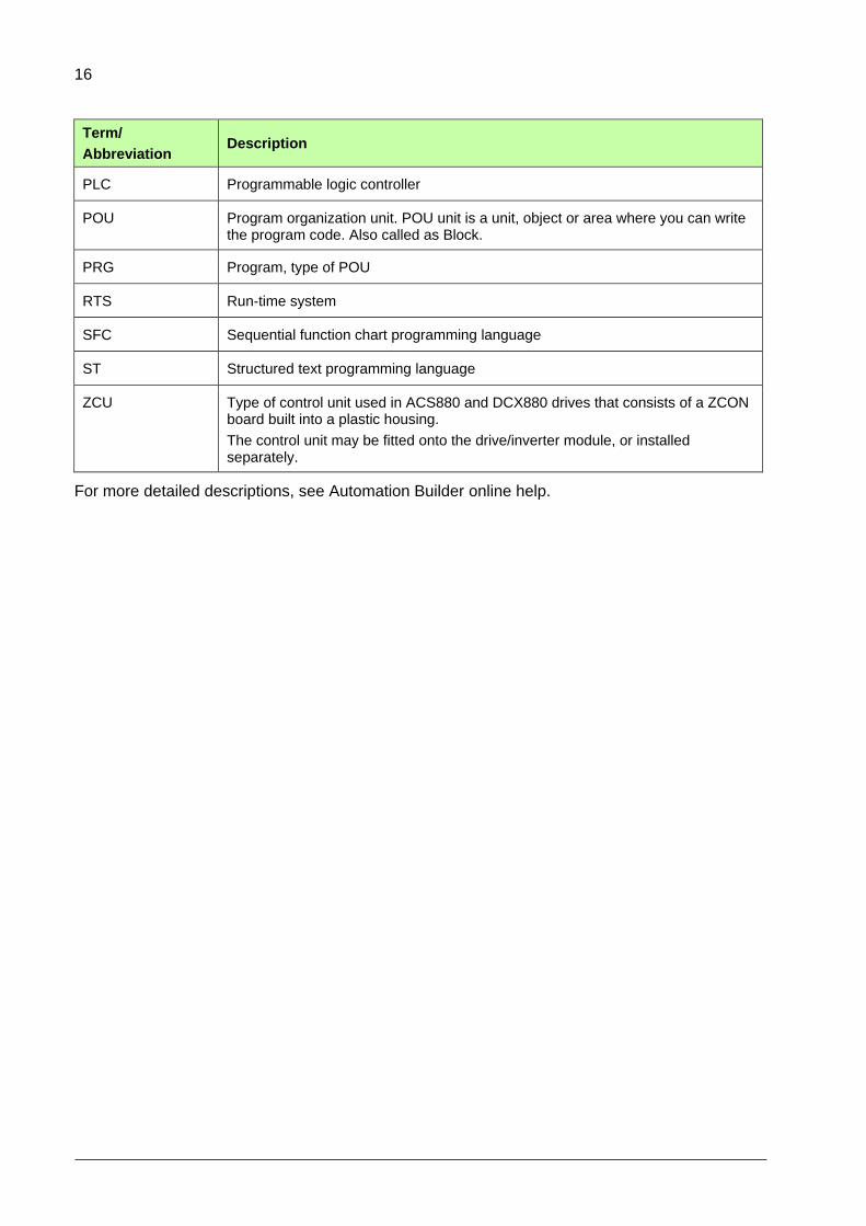
Terms and abbreviations
Term/
Abbreviation Description
ACS-AP-x ACS-AP-I or ACS-AP-S control panel used with ACS880 and DCX880 drives. The control panel has an USB connector enabling a PC tool connection for common architecture drives.
BCU Type of control unit used in ACS880 and DCX880 drives
AB ABB Automation Builder programming tool
CFC Continuous function chart programming language
DDCS Distributed drives communication system.
This protocol is used in communication between ABB drive equipment.
DI Digital input
Drive composer pro ABB Drive composer is a 32-bit Windows application for commissioning and maintaining ABB common architecture drives.
The full version is called Drive composer pro.
DUT Data type unit
FAIO-01 Analog I/O extension module for DDCS bus including 2 bipolar/unipolar current/voltage and 2 unipolar current outputs.
FB Function block, type of POU
FBD Function block diagram programming language
FDCO -01/02 DDCS optical bus communication adapter.
FDIO-01 Digital I/O extension module for DDCS bus inclusing 3-digital inputs and 2-relays.
FEA-03 Extension adapter base board in DDCS link including 2 F-series I/O modules.
FIO-01 Digital I/O extension module for DDCS bus including 4 bidirectional digital inputs/outputs and 2 relays.
FIO-11 Analog and digital I/O extension module for DDCS including 3 analog inputs, 1 analog output and 2 bidirectional digital inputs/outputs.
FUN Function, type of POU
IEC 61131-3 programming
Standardized programming language for industrial automation. Established by the International Electro-technical Commission (IEC)
IL Instruction list programming language
LD Ladder diagram programming language
OPC server OPC DA server interface for Drive composer pro that allows other programs, such as Automation Builder, to communicate with the drive.
PIN IEC variable of the block, which can be connected to other blocks.
16
Term/
Abbreviation Description
PLC Programmable logic controller
POU Program organization unit. POU unit is a unit, object or area where you can write the program code. Also called as Block.
PRG Program, type of POU
RTS Run-time system
SFC Sequential function chart programming language
ST Structured text programming language
ZCU Type of control unit used in ACS880 and DCX880 drives that consists of a ZCON board built into a plastic housing.
The control unit may be fitted onto the drive/inverter module, or installed separately.
For more detailed descriptions, see Automation Builder online help.

17
Getting started
Contents of this chapter
This chapter includes the following information required for programming ACS880 and DCX880
drives using ABB Automation Builder tool:
Quick steps for Setting up the programming environment.
Procedure for Upgrading a new device, Changing an existing device and Viewing
device information.
Setting up the programming environment
The following software installations are required for programming ACS880 and DCX880 drives. For
details of version, refer the corresponding ACS880 or DCX880 drive software release notes or
contact your ABB representative.
ACS880 drive or DCX880 converter with Drive application programming license
(N8010)
ABB Automation Builder 1.2.2 or later
ACS-AP-x control panel and micro USB cable
Drive composer pro 1.10 or later
The Drive composer pro enables setting and monitoring of the drive parameters and signals. The
control panel acts as a USB/RS485 converter between Automation Builder, Drive composer pro and
the drive.
2

18
To setup ACS880 or DCX880 drive programming environment follow the pre-requisites and
installation steps listed below.
Pre-requisites:
The ABB Automation Builder supports Windows XP and Windows 7 (32-bit and 64-bit
versions) operating systems.
You must have Administrator user rights to install Automation Builder.
Installation steps:
1. Install Drive composer pro to enable communication with the target drive. For more details, see
Drive composer user’s manual (3AUA0000094606 [English]).
2. In the Drive composer pro System info Products/Licenses, check that the ACS880 or
DCX880 drive has an active IEC programming license and the drive firmware version is correct.
For details of version, refer the corresponding ACS880 or DCX880 drive software release notes
or contact your ABB representative.
Install ABB Automation Builder version 1.2.2 or later according to the instruction guide included in
the installation media of Automation Builder. All drive application programming related components
are automatically installed as well.
In Automation Builder, select Install Software Packages for Programmable Drive.
Figure 1: Automation Builder – Selecting software packages for installation

19
To allow parallel communication with Automation Builder and Drive composer pro, follow these
steps:
1. In the main menu of Drive composer pro, click View Settings.
2. In the Settings window, select Share connection with Automation Builder check box and
click Save.
Figure 2: Drive Composer Pro settings
After configuring the settings, restart Drive composer pro.
Drive composer now connects to the drive and allows opening the Automation Builder.
Now you can create an application program. See section, Creating application program.

20

21
Overview of drive programming
Contents of this chapter
This chapter provides an overview of ACS880 and DCX880 drive programming environment and a
typical work cycle of drive application programming.
Drive application programming
ABB ACS880 and DCX880 industrial drives can be ordered with the application programming
functionality. It allows you to add your own program code to the drive using the ABB Automation
Builder programming tool (version 1.2.2 or later). The programming method and languages are
based on the IEC 61131-3 programming standard. ABB Automation Builder is also used for
configuring and programming the ABB AC500 PLC family devices.
With the drive application programming, you can create application specific features on top of the
drive firmware functionality. You can utilize the standard and extension I/O and communication
interfaces of the drive along with the appropriate firmware signals. Your program is executed in
parallel with the drive control tasks using the same hardware resources.
In addition, you can create your own parameters and events (faults and warnings) that are visible on
the ACS-AP-x control panel and in the Drive composer pro/entry commissioning tools.
Note: For using ABB Automation Builder online with the drive, enable the drive application programming license in the target drive. See section, Establishing online connection to the drive.
3

22
System diagram
The following simplified system diagram shows the application programming environment in the
same control unit as the drive firmware.
Figure 3: Application programming environment – System diagram
The following list describes the main components for application programming.
Drive control unit:
Run-time system (RTS) executes the application program.
DriveInterface allows input/output mapping between the application program and
drive firmware parameters.
System function library enables access to the drive system services (parameters/
events/ drive-to-drive communication, extension I/O).
User made parameters.
User made events (fault, warnings).
Drive System info includes version information of the application program.
Drive firmware parameters with I/O controls.
D2D function blocks enable drive to drive communication, I/O extension modules, and
so on for application programming.
Drive memory unit:
Creates a permanent version of the application program (Boot application).
Retains values of the application program variables .
Consists of application source code (Note that the size of the memory is limited).

23
Includes symbol and address information of the application program variables for
monitoring purposes.
PC tool programs:
ABB Automation Builder for application program development and online operations.
ABB Drive composer pro for drive parameter, signal, event log monitoring and
settings.
Application program function libraries (for example, ABB standard library).
The USB/ACS-AP-x control panel enables communication between the Automation
Builder, Drive composer pro and the drive.
Programming work cycle
The following steps describes a typical work cycle of the drive application programming tasks of
performing the module:
1. Creating a new project, adding objects, defining the target and first program module in the
Devices tree.
2. Defining the interface to drive firmware parameters (I/O access, drive control) in the
DriveInterface object.
3. Defining user parameters and events (ApplicationParametersandEvents) module in the Devices
tree.
4. Developing the program structure and coding program units.
5. Defining the program execution task configuration editor.
6. Compiling and loading the code using Build menu.
7. Creating boot applications if new parameters, mappings, events or task configuration are added
in the Online menu.
8. Debugging the program code (stepping, forcing variables and breakpoints) in the Online menu.
9. Monitoring program variables in Automation Builder and Drive composer pro from the watch
windows of the View menu.
10. Repeating the cycle from step 2 to 8 for testing the program.
Special tasks
The following special tasks are part of the drive application programming tasks:
1. Saving or restoring the source code to the permanent memory of the drive using the Online
menu.
2. Saving the drive IEC symbol data to permanent memory of the drive from the Devices tree using
the option Add Symbol configuration object to the tree.
3. Naming and versioning the application from the Application properties window or Project
information.
4. Removing the application from the target using Reset origin window on the Online menu.
24
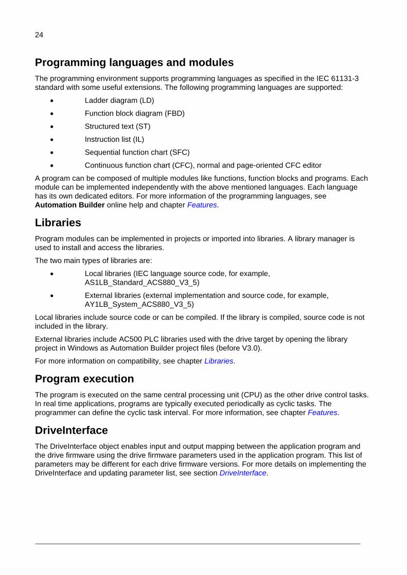
Programming languages and modules
The programming environment supports programming languages as specified in the IEC 61131-3
standard with some useful extensions. The following programming languages are supported:
Ladder diagram (LD)
Function block diagram (FBD)
Structured text (ST)
Instruction list (IL)
Sequential function chart (SFC)
Continuous function chart (CFC), normal and page-oriented CFC editor
A program can be composed of multiple modules like functions, function blocks and programs. Each
module can be implemented independently with the above mentioned languages. Each language
has its own dedicated editors. For more information of the programming languages, see
Automation Builder online help and chapter Features.
Libraries
Program modules can be implemented in projects or imported into libraries. A library manager is
used to install and access the libraries.
The two main types of libraries are:
Local libraries (IEC language source code, for example,
AS1LB_Standard_ACS880_V3_5)
External libraries (external implementation and source code, for example,
AY1LB_System_ACS880_V3_5)
Local libraries include source code or can be compiled. If the library is compiled, source code is not
included in the library.
External libraries include AC500 PLC libraries used with the drive target by opening the library
project in Windows as Automation Builder project files (before V3.0).
For more information on compatibility, see chapter Libraries.
Program execution
The program is executed on the same central processing unit (CPU) as the other drive control tasks.
In real time applications, programs are typically executed periodically as cyclic tasks. The
programmer can define the cyclic task interval. For more information, see chapter Features.
DriveInterface
The DriveInterface object enables input and output mapping between the application program and
the drive firmware using the drive firmware parameters used in the application program. This list of
parameters may be different for each drive firmware versions. For more details on implementing the
DriveInterface and updating parameter list, see section DriveInterface.

25
ApplicationParametersandEvents
The ApplicationParameterandEvents Manager (APEM) object allows creating application parameter
groups, parameters, parameter types, parameter families, units and application events for the drive
in Automation Builder environment. For more details on how to create parameter related tasks and
application events, see section ApplicationParametersandEvents.

26
Creating application program
Contents of this chapter
This chapter describes the procedure to create application program.
For details of instructions and further development steps see chapters DriveInterface, Application
parameter and event creation, Features and Libraries. For more detailed descriptions, see also the
Automation Builder online help.
4

27
Creating a new project
After starting ABB Automation Builder programming environment, you can create a new project.
1. In the Start Page, click New Project or in the main menu, click File New Project.
Figure 4: Automation Builder – Create a new project
2. In the New Project dialog box, select ACS880 or DCX880 project and click OK.
Figure 5: Select a project
Note: If required, rename the project in Name field and select the desired Location in the file
system.

28
3. In the Standard Project dialog box, select the type of control unit in Device drop-down list.
Figure 6 Selecting device
Check the control unit type of the target drive either from the unit itself, from the hardware manual of drives or contact your local ABB representative.
4. In the PLC_PRG in drop-down list, select a programming language and click OK.
You can later add program modules made with other languages to the project.
Figure 7: Select a programming language
A simple project for an ACS880 target drive is created in the Devices tree.
29
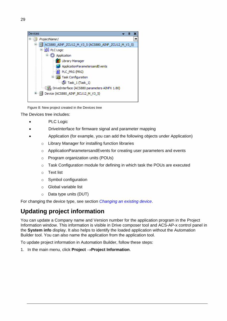
Figure 8: New project created in the Devices tree
The Devices tree includes:
PLC Logic
DriveInterface for firmware signal and parameter mapping
Application (for example, you can add the following objects under Application)
o Library Manager for installing function libraries
o ApplicationParametersandEvents for creating user parameters and events
o Program organization units (POUs)
o Task Configuration module for defining in which task the POUs are executed
o Text list
o Symbol configuration
o Global variable list
o Data type units (DUT)
For changing the device type, see section Changing an existing device.
Updating project information
You can update a Company name and Version number for the application program in the Project
Information window. This information is visible in Drive composer tool and ACS-AP-x control panel in
the System info display. It also helps to identify the loaded application without the Automation
Builder tool. You can also name the application from the application tool.
To update project information in Automation Builder, follow these steps:
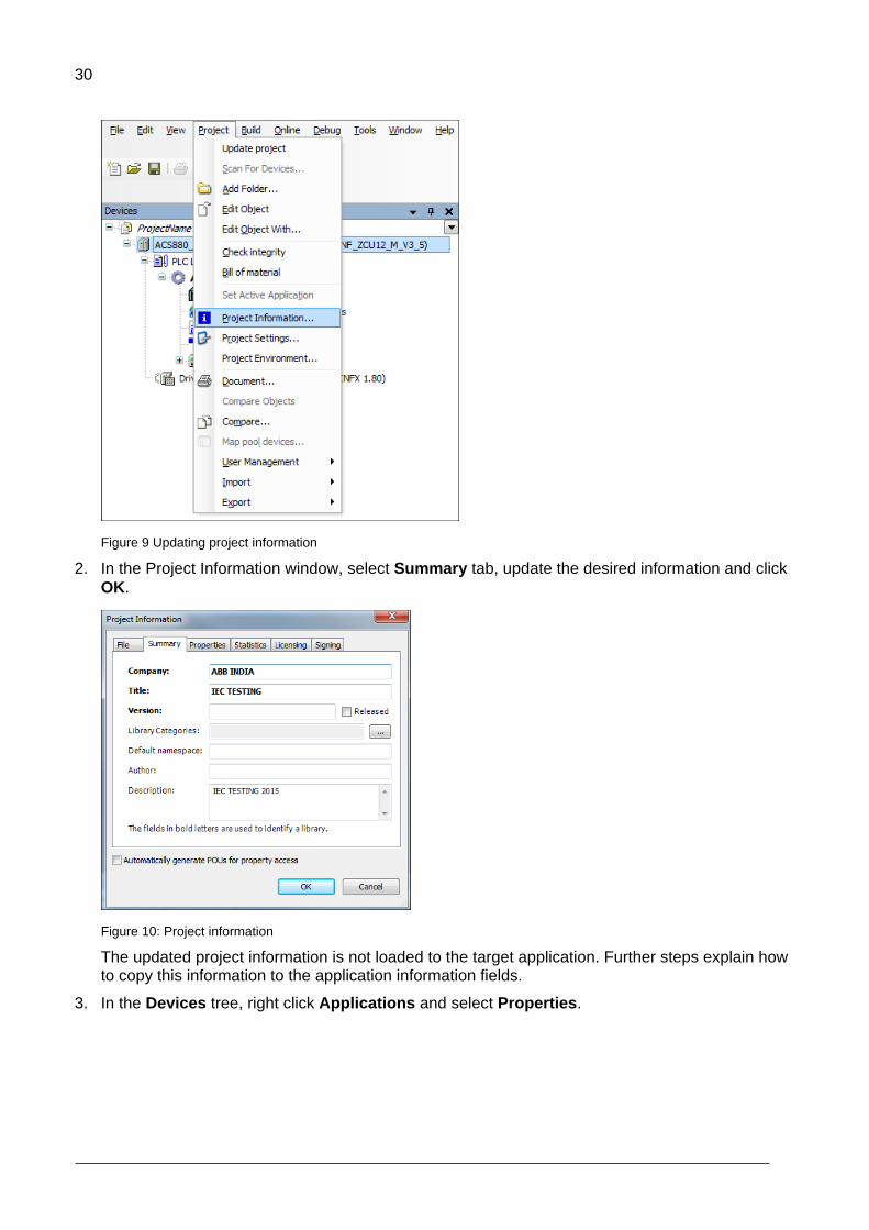
1. In the main menu, click Project Project Information.
30
Figure 9 Updating project information
2. In the Project Information window, select Summary tab, update the desired information and click
OK.
Figure 10: Project information
The updated project information is not loaded to the target application. Further steps explain how to copy this information to the application information fields.
3. In the Devices tree, right click Applications and select Properties.

31
Figure 11 Application properties

32
4. In Properties window, click Information tab and then click Reset to values from project
information and click OK.
Figure 12: Copy information to application information fields
The Automation Builder tool version and project identification code are registered automatically.

33
Appending a new POU
To append a new POU, follow these steps:
1. In the Devices tree, right-click Application and select Add object.
Figure 13 Application add object
2. Select POU and click Add object.
Figure 14 Add POU object
34
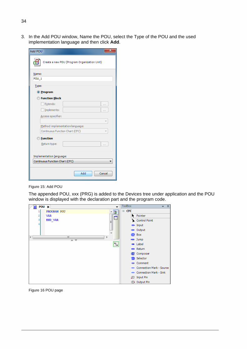
3. In the Add POU window, Name the POU, select the Type of the POU and the used
implementation language and then click Add.
Figure 15: Add POU
The appended POU, xxx (PRG) is added to the Devices tree under application and the POU window is displayed with the declaration part and the program code.
Figure 16 POU page

35
Writing a program code
A program organization unit (POU) is a unit, object or area where you can write the program code.
The units can be created either directly under the Applications in the Devices tree or in a separate
POUs window (View ->POUs or click POUs in the lower left corner).
The POU includes a declaration part (the upper window) and a program code part (the lower
window).
Figure 17: POU window
There are two different types of views for declaration part: a textual view and tabular view . You
can switch between these views by clicking the buttons.
Figure 18 POU view type

36
Continuous function chart (CFC) program
This example shows how to create a new project in the CFC implementation language.
Adding elements
1. In the Devices tree, select the xxx (PRG) under the Application.
Figure 19 PLC PRG
2. In the View menu, select ToolBox.
Figure 20 ToolBox

37
ToolBox components are displayed and are used to add a CFC scheme.
Figure 21: CFC scheme
If an empty ToolBox list is already displayed on the right side of the window, double-click the xxx (PRG) to display the Toolbox and the POU window. You can add, for example, SEL and AND elements (logic operators, functions), use the Box element in the ToolBox list.
3. In the ToolBox list, drag the Box and drop in the program code area.
Figure 22: ToolBox: Box element

38
4. Enter the name of the function or operand in the ??? field.
You can also use Input Assistant to find the function, keyword, and operator. To start Input Assistant, click or press F2.
Figure 23: Input assistant
Note: The number in the upper right corner of the white box indicates the execution order of the function.
5. Right-click on input or output element and select Negate to invert.
Figure 24: Invert input/ouput
39
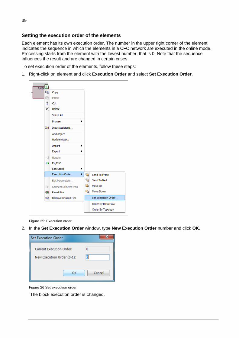
Setting the execution order of the elements
Each element has its own execution order. The number in the upper right corner of the element
indicates the sequence in which the elements in a CFC network are executed in the online mode.
Processing starts from the element with the lowest number, that is 0. Note that the sequence
influences the result and are changed in certain cases.
To set execution order of the elements, follow these steps:
1. Right-click on element and click Execution Order and select Set Execution Order.
Figure 25: Execution order
2. In the Set Execution Order window, type New Execution Order number and click OK.
Figure 26 Set execution order
The block execution order is changed.
40
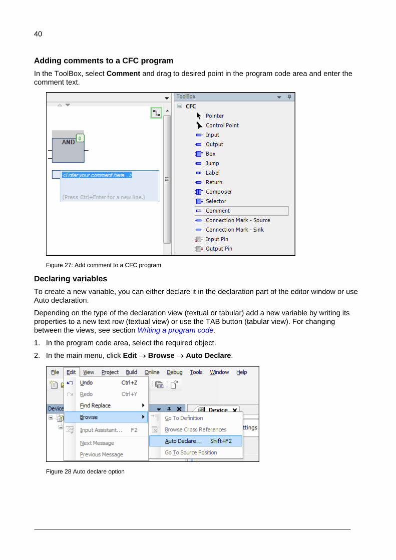
Adding comments to a CFC program
In the ToolBox, select Comment and drag to desired point in the program code area and enter the
comment text.
Figure 27: Add comment to a CFC program
Declaring variables
To create a new variable, you can either declare it in the declaration part of the editor window or use
Auto declaration.
Depending on the type of the declaration view (textual or tabular) add a new variable by writing its
properties to a new text row (textual view) or use the TAB button (tabular view). For changing
between the views, see section Writing a program code.
1. In the program code area, select the required object.
2. In the main menu, click Edit Browse Auto Declare.
Figure 28 Auto declare option

41
The Auto Declare window is displayed.
Figure 29 Auto declare variables
If you enable the option to declare unknown variables automatically (Tools Options SmartCoding), the Auto Declare window opens every time you use an unknown variable in your program and you can declare the variable instantly.
3. Define the Scope, Name and Type of the variable (mandatory).
Scope defines the type of variable (global, input, output, etc.).
Name is a unique identifier of the variable and represents the purpose of the variable.
Type is the IEC data type of the variable.
Optionally, you can also define the Initialization value, Address, Comment or Flags for the variable.
Flags have the following meaning:
CONSTANT means that the variable value cannot be changed and the variable maintains
its initial value all the time.
RETAIN keeps its value over reboot and warm reset.
PERSISTENT is not supported.

42
Adding inputs and outputs
You can add inputs and outputs by selecting ToolBox elements. See section Adding elements.
Figure 30: ToolBox for adding inputs and outputs
Another way to add inputs and outputs straight to a block is to select a pin of a block and start typing
the name of a variable.
1. In the program code area, select the pin of the block.
Figure 31 Naming inputs and outputs
2. Name the input or output by writing the variable name to the block or use input assistant as
described in Declaring variables.
3. To connect the input or output block to a pin, left-click the line connected to the block and drag it
to a pin of another block.
43
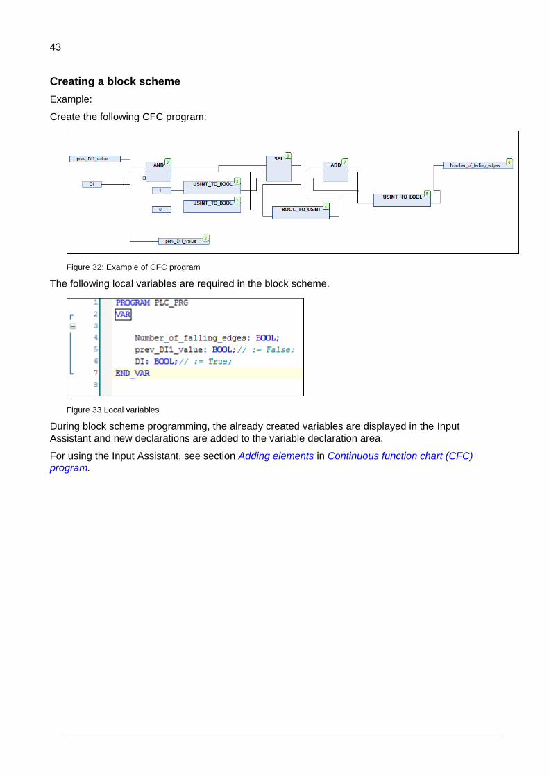
Creating a block scheme
Example:
Create the following CFC program:
Figure 32: Example of CFC program
The following local variables are required in the block scheme.
Figure 33 Local variables
During block scheme programming, the already created variables are displayed in the Input
Assistant and new declarations are added to the variable declaration area.
For using the Input Assistant, see section Adding elements in Continuous function chart (CFC)
program.

44
Preparing a project for download
To prepare a project for download, follow these steps:
1. In the main menu, click Build and select Build.
Figure 34 Build
2. In the View menu, select Messages. A Messages window is displayed.
Check that there are no errors or warnings. Otherwise, check and fix the application.
Figure 35: Build project message window
In the example, the process is successfully completed without any errors or warnings and the
project is ready for download.

45
Establishing online connection to the drive
The Automation Builder communication gateway handles communication between Automation
Builder and the drive. The gateway is a software component that starts automatically at the power-
up of the PC after installing Automation Builder.
Before starting with the communication setup, follow the pre-requisites listed below.
Pre-requisites:
1. Connect PC to a drive through USB port of the ACS-AP-x control panel using a standard USB
data cable (USB Type A <-> USB Type Mini-B). For information on making the control panel to
PC USB connection, see ACS-AP-x control panel user’s manual (3AUA0000085685 [English]).
2. Make sure the ACS-AP-x USB driver is installed. For installation procedure, refer Drive
composer user’s manual (3AUA0000094606 [English]).
3. Make sure the drive has application programming license N8010. To check license information in
Drive composer pro and in ACS-AP-x control panel, go to System info Licenses.
To establish online connection to the target drive after defining the device type, follow these steps:
1. In the Devices tree, double-click ACS880_AINF_ZCU12_14_M_V3_5 and then click
Communication Settings.
Gateway-1 is displayed by default.
Figure 36: Communication settings
Note: If the gateway displays red , the CODESYS Gateway V3 is disabled in local control panel settings.
Figure 37 Gateway disabled

46
2. In the local computer, open Control panel Administrative Tools Services.
3. In the Services window, double-click CODESYS Gateway V3.
Figure 38 Gateway services
A Properties window is displayed.
4. In the Properties window, select the desired Startup type from the available drop-down list and
click OK.
Figure 39 Startup type

47
CODESYS Gateway V3 is enabled and turned to green .
Figure 40 Gateway enabled
5. Ensure that the following default communication settings are correct.
Node Name: Gateway-1
Driver: TCP/IP
IP-Address: localhost (Remote gateways are not scanned)
Port: 1217
6. If Gateway-1 is not available, click Add gateway.
Figure 41 Add new gateway
48
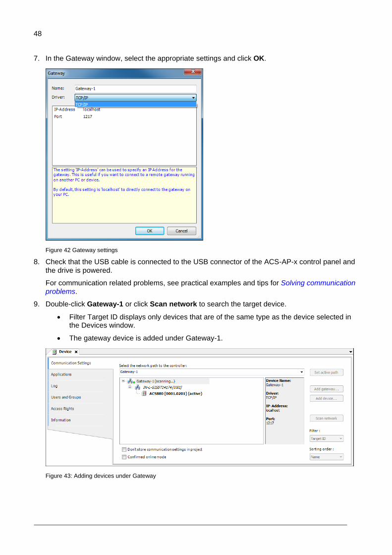
7. In the Gateway window, select the appropriate settings and click OK.
Figure 42 Gateway settings
8. Check that the USB cable is connected to the USB connector of the ACS-AP-x control panel and
the drive is powered.
For communication related problems, see practical examples and tips for Solving communication
problems.
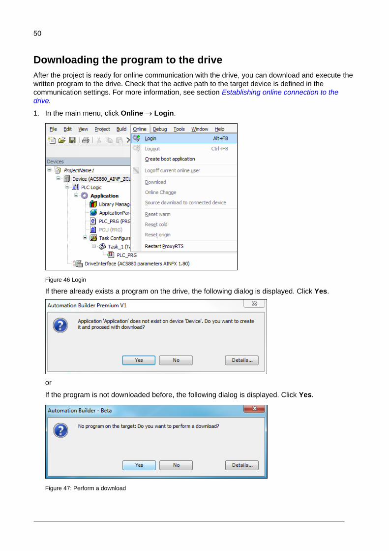
9. Double-click Gateway-1 or click Scan network to search the target device.
Filter Target ID displays only devices that are of the same type as the device selected in the Devices window.
The gateway device is added under Gateway-1.
Figure 43: Adding devices under Gateway

49
10. Under Gateway-1, double-click or right-click the device and click Set active path.
Figure 44: Activating devices under gateway
If the drive has appropriate license code, the selected device is set as active path and is
ready for downloading a program to the drive. See section Downloading the program to the
drive.
If the drive does not have the required license code, the selected device is displayed with no license.
Figure 45: No license notification
Note: To see which port and node is used by each device, see the information in the device name in brackets [GGGG.PPNN] where:
GGGG is the gateway number
PP is the OPC channel number
NN is the OPC node number
50
Downloading the program to the drive
After the project is ready for online communication with the drive, you can download and execute the
written program to the drive. Check that the active path to the target device is defined in the
communication settings. For more information, see section Establishing online connection to the
drive.
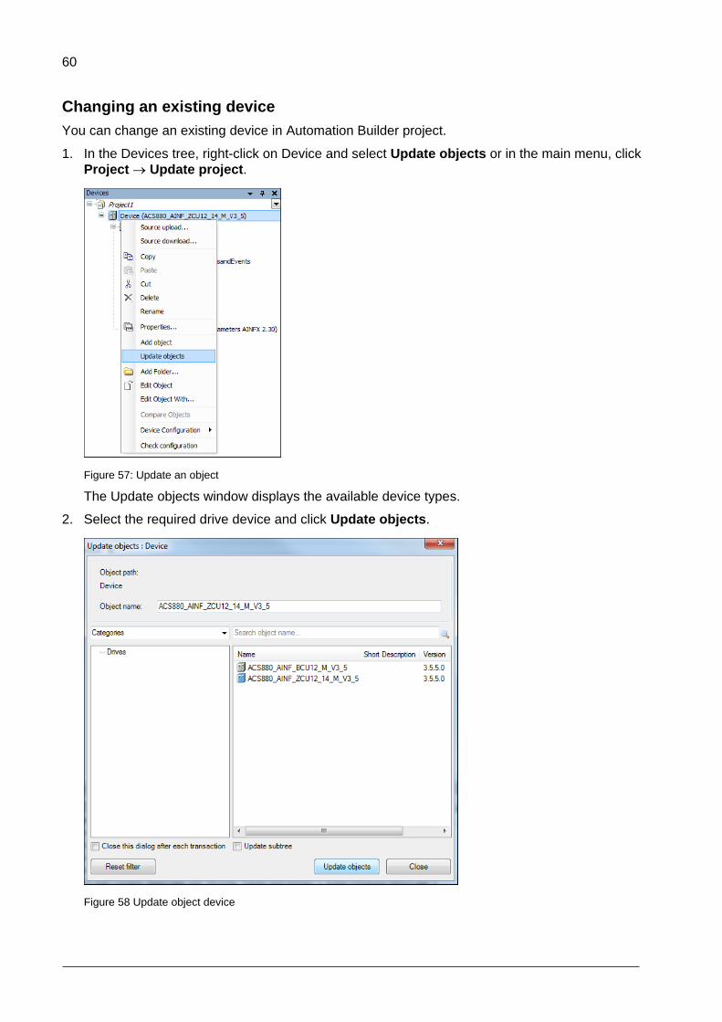
1. In the main menu, click Online Login.
Figure 46 Login
If there already exists a program on the drive, the following dialog is displayed. Click Yes.
or
If the program is not downloaded before, the following dialog is displayed. Click Yes.
Figure 47: Perform a download

51
After the download is complete, the background color of the device name and the application name in the Devices tree changes. The program is in stop mode and the status is shown in brackets [stop]. You can start the program by selecting Start in the Debug menu.
Figure 48 Program in stop mode
For more information on downloading program, see section Application download options in chapter Features.

52
Creating a boot project
The regular downloading moves the application program to the RAM memory of the drive. Creating a
boot project copies the application to the non-volatile memory of the drive memory card and thus
retains the application after power cycle or reboot. For more details, see section Application
download options.
To create a boot project, follow these steps:
1. In the main menu, click Online and select Create boot application.
Figure 49: Create boot application
The following message is displayed. Click Yes to reboot the drive.
Figure 50: Reboot drive after boot project
The reset to default values is optional. If you select Reset application parameters to defaults option, the next boot resets all the application parameters to their default values. The previously set values are not restored from the permanent memory.

53
Select this option when a new application is loaded to drive or a reset origin has been performed or when application parameters of the new application are different from the previously loaded application.
Note: It is recommended to select the Reset application parameters to defaults
option whenever you load a new application to the drive or whenever you change
the parameter definitions of the existing application (APEM).
After creating the boot application, the status changes from STOP to RUN.
2. System prompts to save the boot application, click Save.

54
Executing the program
To execute a program, follow these steps:
1. In the main menu, click Debug Start.
Figure 51: Debug menu
The application status changes to [run] and notifies that the program is executed successfully.
Figure 52 Executing a program
2. To set or change a value of an existing variable, double-click the cell in the Prepared value
column, type a new value and press Enter.
3. In the Debug menu select Write values to apply the prepared value to the variable.
4. In the Debug menu, select Force values to force the prepared value to the variable.
5. In the Debug menu, select Unforce values to unforce a forced value.

55
The variable value is changed. The current variable values are displayed in the Value column
and in the source code near the variable.
6. In the Debug menu, click Stop and then in the Online menu, click Logout to logout.
WARNING! Ignoring the following instruction can cause physical injury or damage to
the equipment.
Do not debug or make changes to drive in the online mode or while the drive is
running to avoid damage to the drive.

56
Features
Contents of this chapter
This chapter describes the device handling information and features supported by Automation
Builder.
Device handling
In the application programming environment, devices represent hardware. The device description file
contains information about the target device (drive) from the programming point of view like the
device identifier, compiler type and memory size. The ABB Automation Builder installation package
installs the device description files automatically.
The device description may be updated later and a new file can be installed. The system monitors
that a project with an incompatible device description file is not loaded to the drive.
The following topics describe device handling:
Viewing device information
Upgrading or adding a new device
Changing an existing device
Viewing software updates
5

57
Viewing device information
To view the detailed device information, follow these steps:
In Devices tree, double-click device and click Information tab.
Figure 53: Device information
The Device ID (1612 0010), Drive FW name (AINFX) and application interface version (3.0.0.1) must
be identical in the project and drive target. In Drive composer pro, use the System info option to
check that the drive target has the corresponding application interface version and device type and
drive firmware name (displayed in parameter 7.04).

58
You can also check if the drive target has the corresponding application interface version and device
ID.
In Drive composer pro, click System info and in Products click More.
Figure 54: Checking drive compatible application and device
The name and version of the available system library is displayed. Make sure this information
matches with the installed system library of the Automation Builder project.
For more information, see parameter 7.23 for Application name and parameter 7.24 for version in
ACS880 FW.
For details of available functions, see chapter Libraries.

59
Upgrading or adding a new device
You can upgrade or add a new device to the programming environment.
1. In the main menu of Automation Builder, click Tools and select Device Repository.
Figure 55 Automation Builder device repository
Device repository window is displayed.
2. Click Install to select device description file.
Figure 56: Device Repository window
3. In the Install Device Description window, browse and select the device description file
(.devdesc.xml) in the file system.
Now you can add a new device to projects or upgrade currently existing devices in the project.
60
Changing an existing device
You can change an existing device in Automation Builder project.
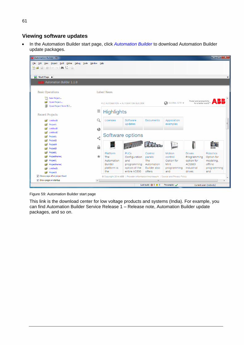
1. In the Devices tree, right-click on Device and select Update objects or in the main menu, click
Project Update project.
Figure 57: Update an object
The Update objects window displays the available device types.
2. Select the required drive device and click Update objects.
Figure 58 Update object device
61
Viewing software updates
In the Automation Builder start page, click Automation Builder to download Automation Builder
update packages.
Figure 59: Automation Builder start page
This link is the download center for low voltage products and systems (India). For example, you
can find Automation Builder Service Release 1 – Release note, Automation Builder update
packages, and so on.

62
Program organization units (POU)
The POU types are:
A program (PRG) may have one or several inputs/outputs. A program may be called by another
POU but cannot be called in a function (FUN). It is not possible to create program instances.
A function (FUN) has always a return value and may have one or several inputs/outputs. The
functions contain no internal state information.
A function block (FB) has no return value but may have one or several outputs as declared in the
variable declaration area. A function block is always called using its instance and the instance
must be declared in a local or global scope.
A created project may have POUs with a specified implementation language. Each added POU
has its own implementation language.
For more detailed description of the POU types, see the IEC programming environment user manual
and the IEC 61131-3 open international standard.
63
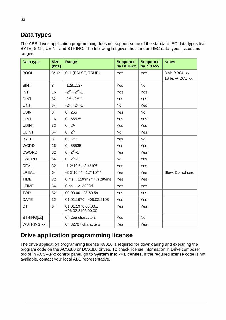
Data types
The ABB drives application programming does not support some of the standard IEC data types like
BYTE, SINT, USINT and STRING. The following list gives the standard IEC data types, sizes and
ranges.
Data type Size (bits)
Range Supported by BCU-xx
Supported by ZCU-xx
Notes
BOOL 8/16* 0, 1 (FALSE, TRUE) Yes Yes 8 bit BCU-xx
16 bit ZCU-xx
SINT 8 -128...127 Yes No
INT 16 -215...215-1 Yes Yes
DINT 32 -231...231-1 Yes Yes
LINT 64 -263...263-1 No Yes
USINT 8 0...255 Yes No
UINT 16 0...65535 Yes Yes
UDINT 32 0...232 Yes Yes
ULINT 64 0...264 No Yes
BYTE 8 0…255 Yes No
WORD 16 0...65535 Yes Yes
DWORD 32 0...232-1 Yes Yes
LWORD 64 0...264-1 No Yes
REAL 32 -1.2*10-38...3.4*1038 Yes Yes
LREAL 64 -2.3*10-308...1.7*10308 Yes Yes Slow. Do not use.
TIME 32 0 ms... 1193h2m47s295ms Yes Yes
LTIME 64 0 ns...~213503d Yes Yes
TOD 32 00:00:00...23:59:59 Yes Yes
DATE 32 01.01.1970...~06.02.2106 Yes Yes
DT 64 01.01.1970 00:00... ~06.02.2106 00:00
Yes Yes
STRING[xx] 0...255 characters Yes No
WSTRING[xx] 0...32767 characters Yes Yes
Drive application programming license
The drive application programming license N8010 is required for downloading and executing the
program code on the ACS880 or DCX880 drives. To check license information in Drive composer
pro or in ACS-AP-x control panel, go to System info -> Licenses. If the required license code is not
available, contact your local ABB representative.

64
Application download options
Before executing an application in the drive, download the application to the drive memory. After
downloading, the application software is embedded in the firmware of the drive and has access to
system resources.
Note: It is not recommended to download a program to the RAM memory when the drive
is in RUN mode. The drive must be in STOP mode and Start inhibits must be possible to
set.
Before download, ensure that there is no fieldbus device, M/F-link or D2D-link connected to the drive
and Drive composer is not running data monitoring or back-up/restore at same time.
There are two different download options:
Download – This is a regular download method that copies the compiled application
to the drive RAM memory. As a result, it is possible to execute the application, but
after a power cycle or reboot the memory is erased. This download method does not
alter an application that is located in the drive boot memory (ZMU) and the original
application is available for use after a reboot.
Create boot application – This download method copies the application to the non-
volatile memory of the drive memory card. This way the application remains intact
after a power cycle or reboot. You should be logged into the drive to perform this
operation. Features that can work only after restarting the drive should be
downloaded with this method.
Create boot application command (Online Create boot application) also includes booting the drive. Rebooting stops the execution of the complete drive firmware for some time. For this reason, it is allowed only when the drive is stopped and start inhibition is granted to the Automation Builder.
Note:
Firmware parameter mapping, task configuration, application parameters and
event configuration are activated only after the boot application is loaded and
the drive is booted.
Start inhibition is not granted if the drive is running, disabled (DIL, Safety
function active) or faulted. Make sure that these conditions do not exist before
downloading the program.

65
Removing the application from the target
Use the Reset option if the application includes many changes like application parameter changes or
the application is replaced by another application. If the target already includes an application, use
the Reset origin selection in the Online tab before downloading a new application.
This command removes (clears all) old applications from the target and all the application related
references. Use this command at least once before the final version of application is loaded. The
command can be used only in the online mode. See also Reset options.
When you are prompted with the following message, click Yes.
Figure 60: Initiate reset origin
After you initiate the Reset origin option, the following message is displayed. Click Yes. The
command is executed only if Automation Builder receives the permission from the drive.
Figure 61: Confirm reset origin

66
Retain variables
Retain variables includes the RETAIN flag used to retain values throughout the drive reboot and
warm reset. A cold reset sets the retain variable to its initial value. The values of retain variables are
cyclically stored in the flash memory of the drive and restored to the stored value after the restart of
the program. The retain variables are stored in a separate 256-byte memory area which defines the
limits of their amount.
WARNING! In a function block, do not declare a local variable as RETAIN because the
complete instance of the function block is saved in the retain memory area and this large
function block instance may lead to running out of memory space.
In firmware version 1.7 and later, the power control board works with the parameter settings:
If parameter 95.04 = Internal 24V, retain values are saved immediately at the time the
drive loses power, meaning it is not cyclical.
If parameter 95.04 = External 24V, retain values are saved at periodic intervals of 3
minutes. So the recovered variable may not be the recent value.
Note: Declaring a local variable in a function as RETAIN has no effect and the variable
is not saved in the retain memory area.
The existing retain variables cannot be linked to application parameters.
Task configuration
The task configuration object handles call configuration of programs. A task is a project unit that
defines which program is called in the project and when it is called. The project can have more than
one task with different time levels.
There are two types of tasks:
Cyclic task (Task_1, Task_2 and Task_3) – These tasks are processed cyclically
according to the task cycle time interval. The following table lists the time intervals
available for cyclic application programs. The highest priority is given to the task with
the shortest execution interval.
Task Time interval
Task_1 1 … 100 ms
Task_2 10 … 100 ms
Task_3 100 … 1000 ms
Pre_task – This task is executed only once at start-up of the application program.
This feature is useful for one time initialization. POUs (blocks) assigned into this task
are executed before the start of cyclic tasks.
Note: The application program consists of its own quota of CPU resources. If the limit
exceeds, the drive tips to task overflow fault. For details, see ACS880 Firmware
manual.

67
Adding tasks
To add tasks to Task Configuration, follow these steps:
1. In the Devices tree, right-click Task Configuration and select Add Object.
Figure 62 Task configuration
2. Select Task and click Add object.
Figure 63 Task

68
3. In the Task drop-down list, select a task and click Add.
Figure 64: Add tasks
The selected tasks are added in the Task Configuration object.
Figure 65: Tasks added
4. Click Add POU in the newly added Task_2 screen.

69
5. In the Input Assistant window, click Categories and then select PLC_PRG and click OK.
Figure 66 Add POU input assistant
6. PLC_PRG is added to Task_2. Drag PLC_PRG to Task Configuration object.
Figure 67 New PLC PRG
70
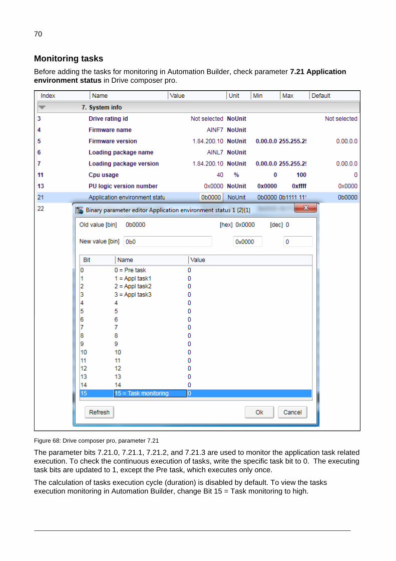
Monitoring tasks
Before adding the tasks for monitoring in Automation Builder, check parameter 7.21 Application
environment status in Drive composer pro.
Figure 68: Drive composer pro, parameter 7.21
The parameter bits 7.21.0, 7.21.1, 7.21.2, and 7.21.3 are used to monitor the application task related
execution. To check the continuous execution of tasks, write the specific task bit to 0. The executing
task bits are updated to 1, except the Pre task, which executes only once.
The calculation of tasks execution cycle (duration) is disabled by default. To view the tasks
execution monitoring in Automation Builder, change Bit 15 = Task monitoring to high.

71
To add task monitoring view in Automation Builder, follow these steps:
1. In the Devices tree, double click Task Configuration.
2. Click Monitor tab to check the status report of available tasks.
The status report of available tasks appears.
Figure 69: Task monitoring view
Note: The values in the task monitoring view are updated only setting the parameter
7.21.15 to high in Drive composer pro. This setting is configured again after the power
cycle or boot or control board.
You can evaluate the total (task 1-3) CPU load using the parameters 7.40 IEC Application Cpu
usage peak and 7.41 IEC Application Cpu load average. For parameter descriptions, see ACS880
primary control program firmware manual [3AUA0000085967 (English)].
72
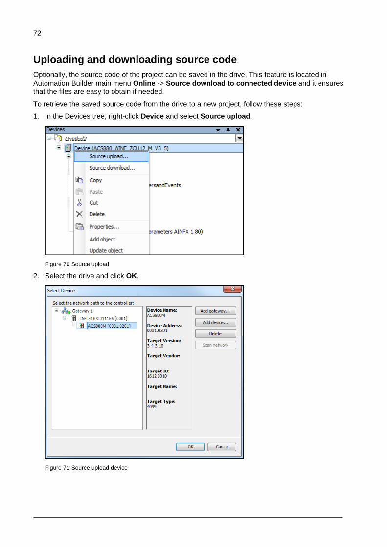
Uploading and downloading source code
Optionally, the source code of the project can be saved in the drive. This feature is located in
Automation Builder main menu Online -> Source download to connected device and it ensures
that the files are easy to obtain if needed.
To retrieve the saved source code from the drive to a new project, follow these steps:
1. In the Devices tree, right-click Device and select Source upload.
Figure 70 Source upload
2. Select the drive and click OK.
Figure 71 Source upload device

73
The size of the source code is limited to 500 KB. Check the archiving option to minimize the source
code size (File Project Archive Save/Send Archive…). Note that referenced devices and
libraries are needed, the rest is optional.
Note: If the source code is saved on the ZMU memory unit, you can retrieve the program
with another PC without the authors consent unless the project is password protected.

74
Adding symbol configuration
To add symbol configuration in Automation Builder project, follow these steps:
1. In the Devices tree, right-click Application and select Add object.
Figure 72 Add object for symbol configuration
2. Select Symbol configuration and click Add object.
Figure 73 Symbol configuration

75
3. In the Add Symbol configuration window, click Add.
Figure 74 Add symbol configuration
Symbol configuration object is added to the project.
Figure 75 Symbol configuration object
After adding Symbol configuration object to the project, the IEC variable to symbol data is loaded
into the drive during the create boot application download. See section Application download
options. This feature provides Drive composer pro access to the application variables which is used
for graphical monitoring and debugging.
For more information on the Symbol configuration editor and adding variables, see Automation
Builder Online help.

76
Debugging and online changes
The following debugging features and variable forcing are supported:
Start / stop program execution
Setting breakpoints
Stepping code line by line or by function
Forcing variables (constant setting of variable values)
Writing variables (single setting of variable values)
Note: Online changes of the program code are not supported.
WARNING! Ignoring the following instruction can cause physical injury or damage to
the equipment.
Do not set breakpoints and force variables on a running drive that is connected to
motor.
Safe debugging
When debugging the application program of a running drive connected to motor in the online mode,
avoid the following actions:
stopping the application program
setting breakpoints to the application program
forcing variable values
assigning values to outputs
changing the values of a local variable in function blocks
assigning invalid input values
Breakpoints stop the entire application, instead of just the task that has the currently active
breakpoint.
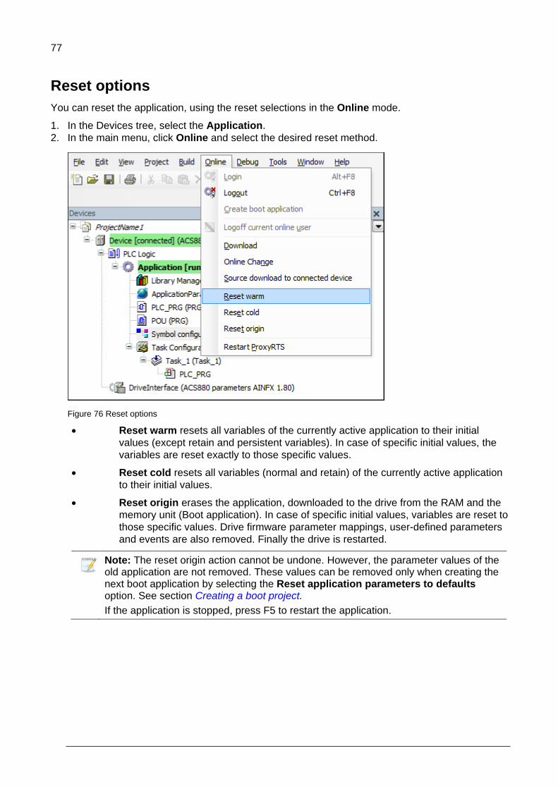
77
Reset options
You can reset the application, using the reset selections in the Online mode.
1. In the Devices tree, select the Application.
2. In the main menu, click Online and select the desired reset method.
Figure 76 Reset options
Reset warm resets all variables of the currently active application to their initial
values (except retain and persistent variables). In case of specific initial values, the
variables are reset exactly to those specific values.
Reset cold resets all variables (normal and retain) of the currently active application
to their initial values.
Reset origin erases the application, downloaded to the drive from the RAM and the
memory unit (Boot application). In case of specific initial values, variables are reset to
those specific values. Drive firmware parameter mappings, user-defined parameters
and events are also removed. Finally the drive is restarted.
Note: The reset origin action cannot be undone. However, the parameter values of the old application are not removed. These values can be removed only when creating the next boot application by selecting the Reset application parameters to defaults option. See section Creating a boot project.
If the application is stopped, press F5 to restart the application.

78
Memory limits
To see the effective size of the program, follow these steps:
In the main menu, click Build and select Clean or Clean All to remove temporary code sections
from the program.
Figure 77 Build clean
The build report shows the actual memory allocation.
Memory area 0 is assigned for code and data. Memory area 1 is assigned for retain variables.
See the example screen below.
Figure 78: Memory limits – example
Note: To optimize the memory consumption, avoid using function blocks and
unnecessary variable definitions.

79
CPU limitation
The maximum execution load of the application is limited to a certain value of 5 to 15% depending
on the drive type. To know the actual load limit, contact your local ABB representative.
Use parameter 7.11 Cpu usage to check the application load which monitors the CPU load. To know
the load difference, compare the values between with and without the application. Ensure that the
difference value is not greater than the value limit. If the application exceeds the limit, the drive trips
to the task overload fault 6481. The fault is registered to the event log of the drive and the fault-
specific AUX code indicates the overloaded tasks (10 = task 1, 11 = task 2 and 12= task 3).
You can evaluate the total (task 1-3) CPU load using the parameters 7.40 IEC Application Cpu
usage peak and 7.41 IEC Application Cpu load average. For parameter descriptions, see ACS880
primary control program firmware manual [3AUA0000085967 (English)].
Perform CPU load tests to ensure that the drive is capable of adequately running the application.
Enable the required drive functions during the execution of the application. For example, motor
control, communication modules, encoders, and so on.
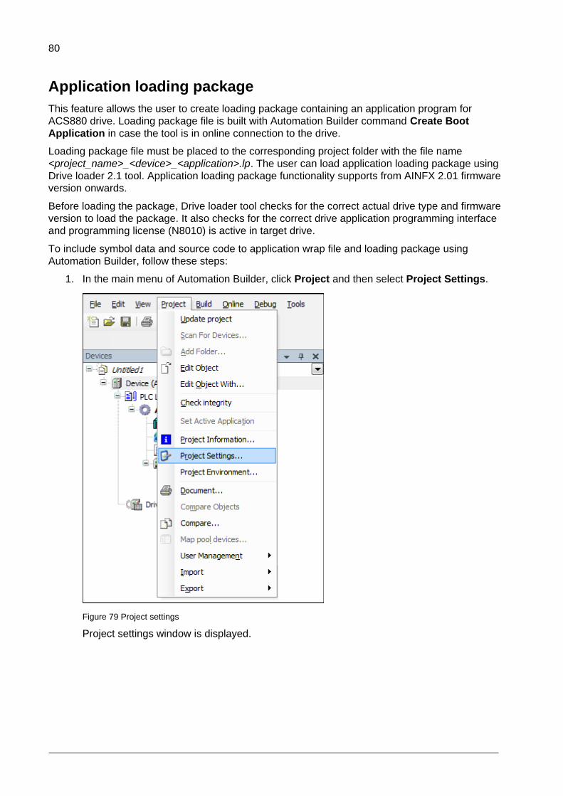
80
Application loading package
This feature allows the user to create loading package containing an application program for
ACS880 drive. Loading package file is built with Automation Builder command Create Boot
Application in case the tool is in online connection to the drive.
Loading package file must be placed to the corresponding project folder with the file name
<project_name>_<device>_<application>.lp. The user can load application loading package using
Drive loader 2.1 tool. Application loading package functionality supports from AINFX 2.01 firmware
version onwards.
Before loading the package, Drive loader tool checks for the correct actual drive type and firmware
version to load the package. It also checks for the correct drive application programming interface
and programming license (N8010) is active in target drive.
To include symbol data and source code to application wrap file and loading package using
Automation Builder, follow these steps:
1. In the main menu of Automation Builder, click Project and then select Project Settings.
Figure 79 Project settings
Project settings window is displayed.
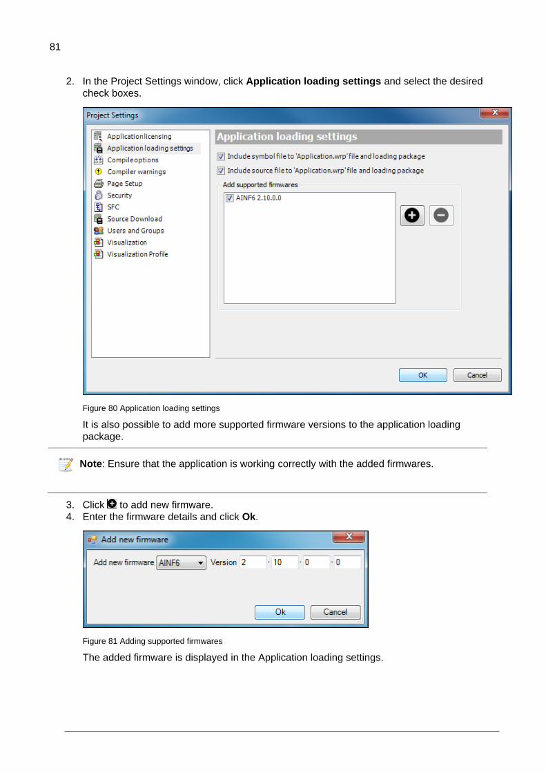
81
2. In the Project Settings window, click Application loading settings and select the desired
check boxes.
Figure 80 Application loading settings
It is also possible to add more supported firmware versions to the application loading
package.
Note: Ensure that the application is working correctly with the added firmwares.
3. Click to add new firmware.
4. Enter the firmware details and click Ok.
Figure 81 Adding supported firmwares
The added firmware is displayed in the Application loading settings.

82
Downloading loading package to a drive
Drive loader tool is used to download loading package to common platform drives.
1. Start Drive loader tool. 2. Click Open to download a loading package or click Scan to scan for a connected device.
Figure 82 Drive loader tool

83
3. Select the desired loading package file (.lp) and click Open.
Figure 83 Loading package
4. Select the desired drive and click Select.
Figure 84 Drive selection

84
5. In the Software Set drop-down list, select the appropriate selection.
1: Loads new application, set application parameters to default and removes user sets from the drive.
2: Loads new application.
3: Removes the application from the drive (reset origin). Before using this option, the user must first load application loading package using options 1 or 2.
4: Removes user sets from the drive.
Figure 85 Software set
6. Select the desired communication Serial port and click Download. Before starting downloading, drive loader checks for the following:
Correct control board (ZCU/BCU).
Same device ID in Automation Builder project and drive control board.
Correct version of application environment.
Programming license loaded to target (N8010).
FW version supported in loading package.
Note: Before starting downloading, ensure Automation Builder and Drive composer are
not running at the same time.
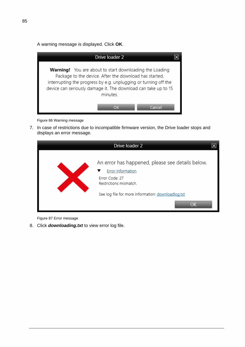
85
A warning message is displayed. Click OK.
Figure 86 Warning message
7. In case of restrictions due to incompatible firmware version, the Drive loader stops and displays an error message.
Figure 87 Error message
8. Click downloading.txt to view error log file.

86
DriveInterface
Contents of this chapter
This chapter describes how to implement DriveInterface and map input/output settings between the
application programs and drive firmware parameters.
Implementing DriveInterface
The interface between the drive firmware and application is implemented using DriveInterface.
Figure 88: DriveInterface
DriveInterface consists of all drive firmware parameters list that can be used in the application
program. This list is specific for each drive firmware (a new firmware may have new parameters).
6

87
You can assign a parameter to be an input for the application program and define that the parameter
is read at the beginning of the task execution. Similarly, user can assign parameters to be an output
of the application.
Figure 89: DriveInterface – Assigning parameters for outputs in the application
Note:
The parameter to IEC variable mappings is valid only after creating a boot
application. For more details, see section Application download options.
Drive interface is not completely covering all drive parameters. If the firmware
parameter is not available in the drive interface list, use the AY1LB library
functions to read/write firmware parameters.
In order to fully remove drive parameter settings from drive, use Reset origin
option. Also, re-save user sets (see parameter 96.08) after removing or
replacing the application. As user set may have incorrect mapping of firmware
parameter to non-existing application.

88
Selecting the parameter set
A drive can have different parameters depending on the firmware version. Before performing
parameter modification, ensure that the correct parameter set is selected in DriveInterface. The
changes to parameter set in DriveInterface removes all parameter mapping data.
To change the currently selected parameter set, follow these steps:
1. In the Devices tree, right-click DriveInterface and select Update objects.
Figure 90 DriveInterface update object
2. In the Update object window, select the correct parameter set for the current target and click
Update objects.
Figure 91 DriveInterface parameter set
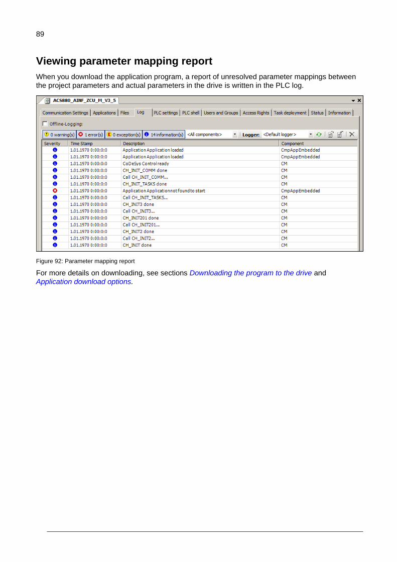
89
Viewing parameter mapping report
When you download the application program, a report of unresolved parameter mappings between
the project parameters and actual parameters in the drive is written in the PLC log.
Figure 92: Parameter mapping report
For more details on downloading, see sections Downloading the program to the drive and
Application download options.
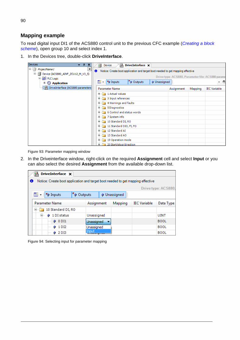
90
Mapping example
To read digital input DI1 of the ACS880 control unit to the previous CFC example (Creating a block
scheme), open group 10 and select index 1.
1. In the Devices tree, double-click DriveInterface.
Figure 93: Parameter mapping window
2. In the Driveinterface window, right-click on the required Assignment cell and select Input or you
can also select the desired Assignment from the available drop-down list.
Figure 94: Selecting input for parameter mapping
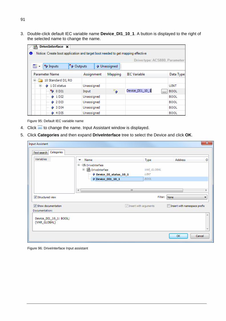
91
3. Double-click default IEC variable name Device_DI1_10_1. A button is displayed to the right of
the selected name to change the name.
Figure 95: Default IEC variable name
4. Click to change the name. Input Assistant window is displayed.
5. Click Categories and then expand DriveInterface tree to select the Device and click OK.
Figure 96: DriveInterface Input assistant

92
IEC variable name is changed.
Figure 97 DriveInterface variable name
Note: If you want to select existing variable DI1 from the POU variable list, expand
Application and under POU, select DI1. DI1 is connected to drive parameter 10.1. DI
status bit 0.
Figure 98 Existing variable
The mapped parameters are available as IEC variables in the program editors (press F2).
Note: Bit and value pointer parameters can be used as outputs and then the pointer is
linked directly to the application memory.
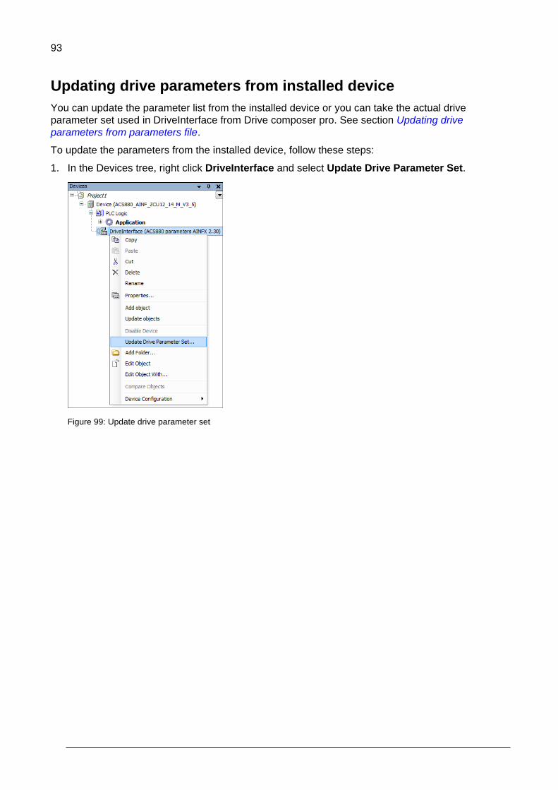
93
Updating drive parameters from installed device
You can update the parameter list from the installed device or you can take the actual drive
parameter set used in DriveInterface from Drive composer pro. See section Updating drive
parameters from parameters file.
To update the parameters from the installed device, follow these steps:
1. In the Devices tree, right click DriveInterface and select Update Drive Parameter Set.
Figure 99: Update drive parameter set

94
2. In From installed device option, expand Miscellaneous and select the device and then click
Update.
Figure 100: Update parameter from installed device
The parameter list from the selected device is displayed.
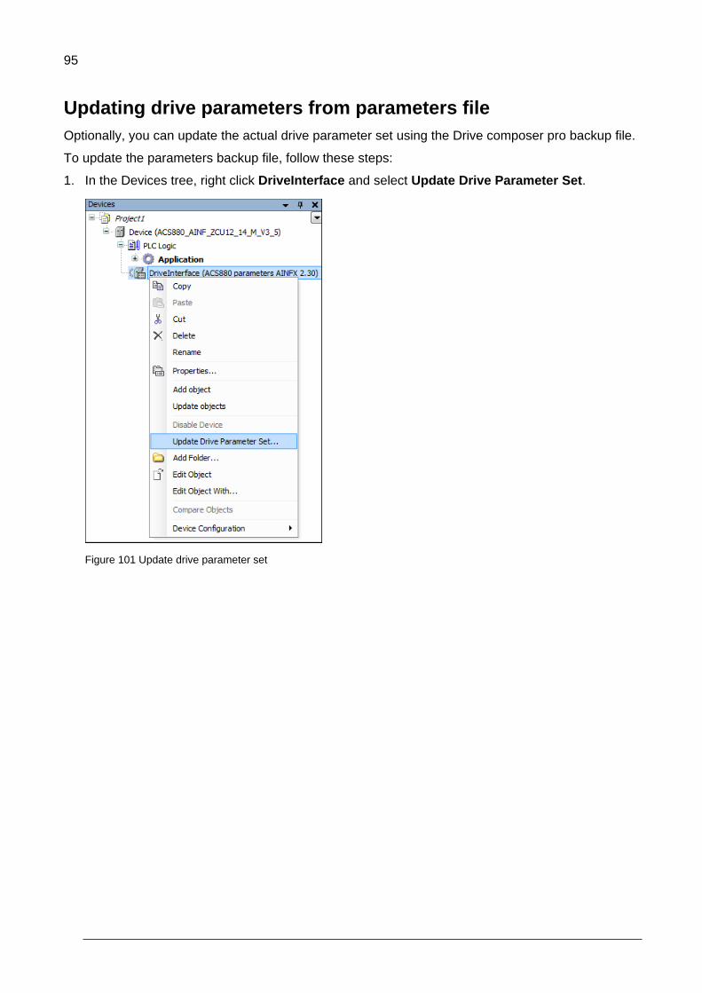
95
Updating drive parameters from parameters file
Optionally, you can update the actual drive parameter set using the Drive composer pro backup file.
To update the parameters backup file, follow these steps:
1. In the Devices tree, right click DriveInterface and select Update Drive Parameter Set.
Figure 101 Update drive parameter set

96
2. In the Update parameter set window, select From parameter file option and browse to select
dcparams (.xml) backup file and then click Update.
Figure 102: Select parameter file
The changes/deleted parameters are displayed. Click OK.

97
Setting parameter view
In Automation Builder, you can select the required parameter details to view in the ACS-AP-x control
panel and the Drive composer pro display:
1. In the Devices tree, double-click DriveInterface.
Figure 103 DriveInterface parameter view
2. In the upper-left corner of the DriveInterface window, select Settings.
Figure 104: DriveInterface settings

98
3. Select the required view option for the corresponding parameter and click OK.
Figure 105: Hide options
The selected options in the view list are displayed in the DriveInterface parameter window.
99
Application parameter and events
Contents of this chapter
This chapter describes how to use the Parameter Manager and provides detailed information on
parameter settings.
7
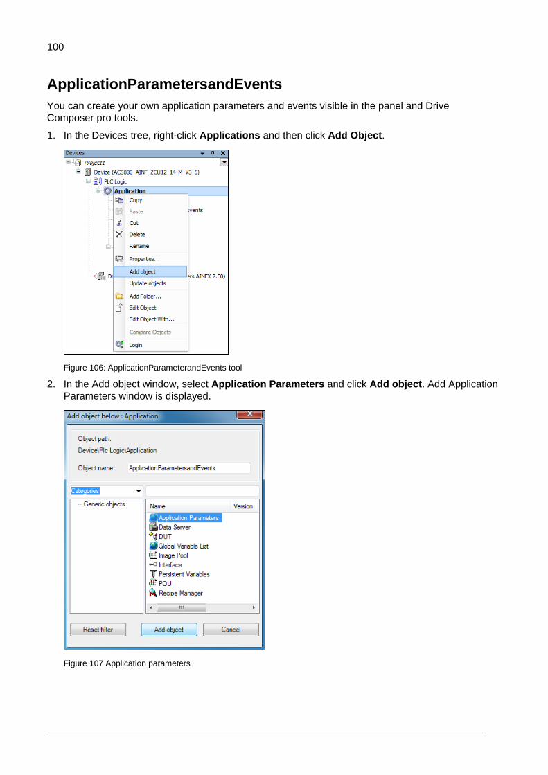
100
ApplicationParametersandEvents
You can create your own application parameters and events visible in the panel and Drive
Composer pro tools.
1. In the Devices tree, right-click Applications and then click Add Object.
Figure 106: ApplicationParameterandEvents tool
2. In the Add object window, select Application Parameters and click Add object. Add Application
Parameters window is displayed.
Figure 107 Application parameters
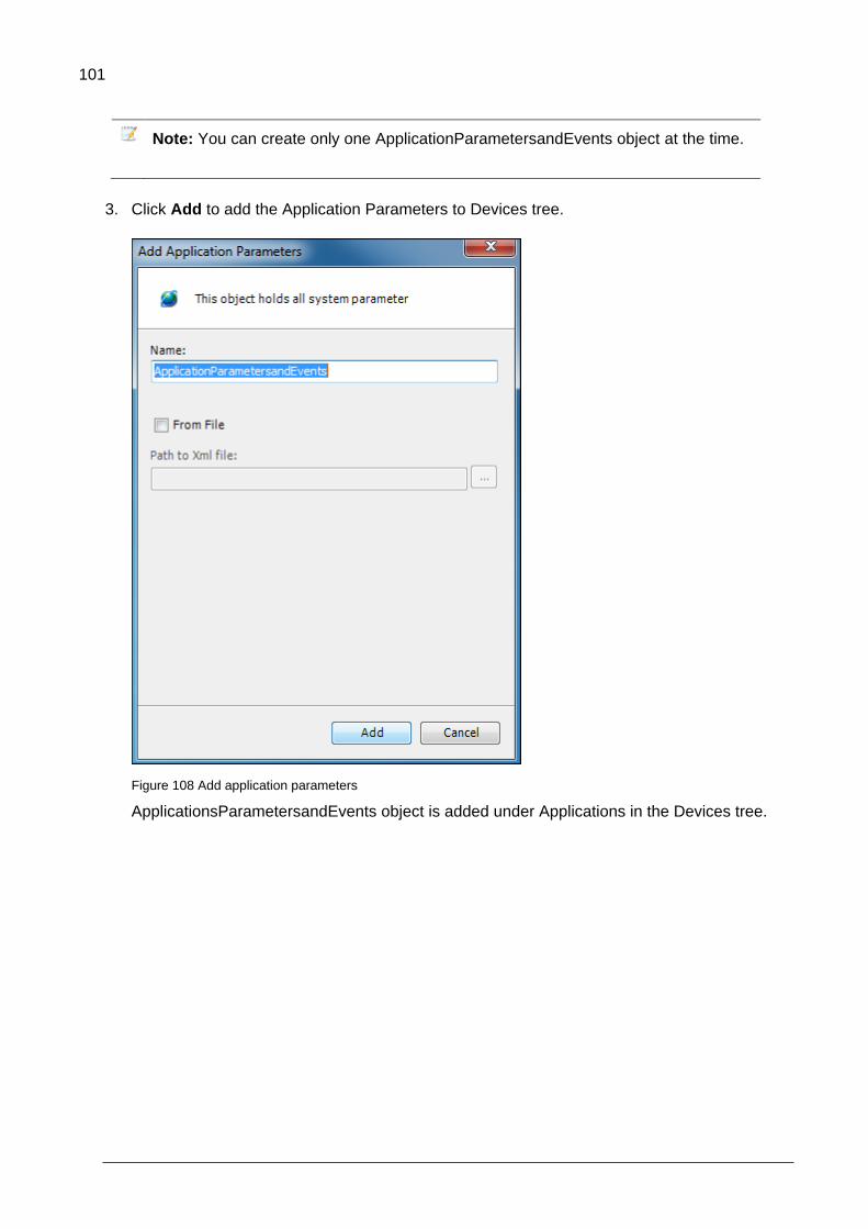
101
Note: You can create only one ApplicationParametersandEvents object at the time.
3. Click Add to add the Application Parameters to Devices tree.
Figure 108 Add application parameters
ApplicationsParametersandEvents object is added under Applications in the Devices tree.

102
ParameterManager
In the ParameterManager window, you can create new groups of parameters, parameter families,
selection lists, units, events and language translations for the names of all the previous items.
In the Devices tree/Application, double-click the ApplicationParametersandEvents object. The
ParameterManager window is displayed.
Figure 109: Parameter manager window
Creating parameter groups
All the drive parameters belong to a specific parameter group. Before creating any new parameters
create a new parameter group. Ensure that all the groups have unique name and number. You can
change the group number and name. You can also add translations into other languages in addition
to the default language which is English.
In the ParameterManager window, click to add group.
Figure 110 Adding parameter group
ParameterManager automatically selects the first free parameter group number that is not used in the drive firmware or ParameterManager.
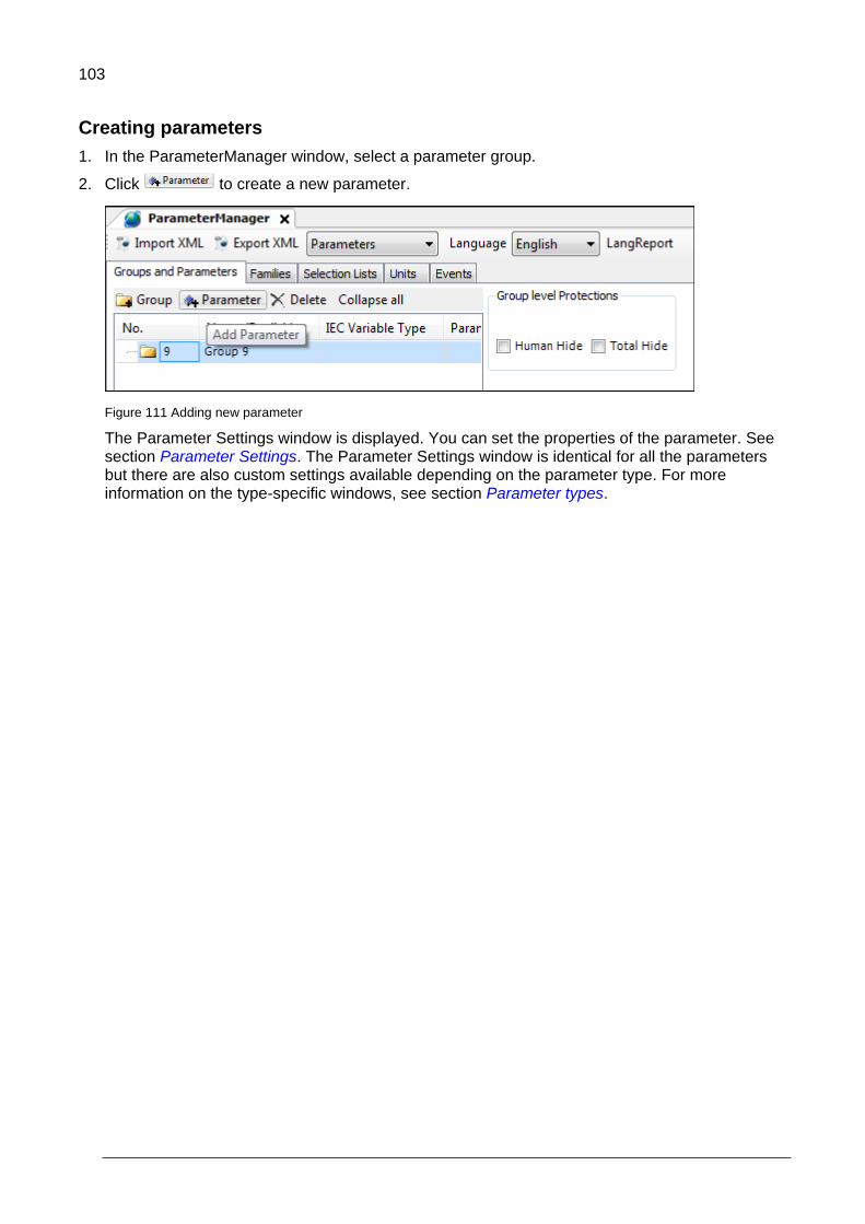
103
Creating parameters
1. In the ParameterManager window, select a parameter group.
2. Click to create a new parameter.
Figure 111 Adding new parameter
The Parameter Settings window is displayed. You can set the properties of the parameter. See section Parameter Settings. The Parameter Settings window is identical for all the parameters but there are also custom settings available depending on the parameter type. For more information on the type-specific windows, see section Parameter types.

104
3. In the Parameter Settings window, enter the Name of a parameter and click Add.
Figure 112 Naming parameter
The new parameter added to the selected group.
Figure 113 New parameter
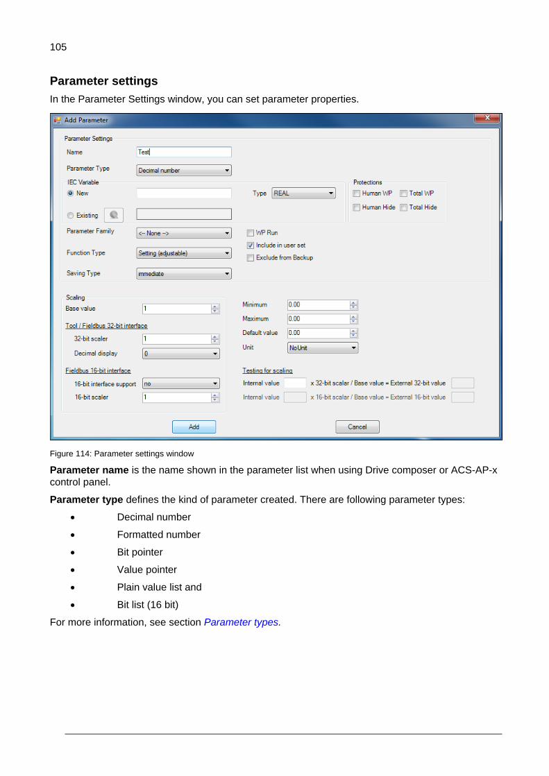
105
Parameter settings
In the Parameter Settings window, you can set parameter properties.
Figure 114: Parameter settings window
Parameter name is the name shown in the parameter list when using Drive composer or ACS-AP-x
control panel.
Parameter type defines the kind of parameter created. There are following parameter types:
Decimal number
Formatted number
Bit pointer
Value pointer
Plain value list and
Bit list (16 bit)
For more information, see section Parameter types.
106
IEC variable name is used to define an IEC variable for the parameter.
The New option maps the parameter to a new IEC variable. If you do not give a name
for the new IEC variable, the parameter name is used as the IEC variable name.
When you create a new IEC variable, you must select the variable type, for example, REAL. For more information on the variable types, see section Data types in chapter Features. The selected parameter type restricts the variable type selection and only the allowed types are shown in the IEC variable/Type list.
The Existing option maps the parameter to an already existing IEC variable by
finding the parameter from the list of the Input Assistant or writing the name to the
field.
Parameter family includes a parameter as part of the parameter family and inherits the settings
defined for the family. For more information, see section Parameter families.
Function types are flag configurations for parameters which determine the parameter behavior with
the ACS-AP-x control panel and PC tool displays. There are five different configurations:
Setting (adjustable) – This function type is a generic configuration parameter. When
a parameter with this function type is changed by ACS-AP-x control panel or Drive
composer, the changed value is saved. If the value is written cyclically, the saving
type for the parameter must be no (for example, motor speed limits).
Setting (reverts to default) – This function type is used for requesting a function.
When this request is processed, the parameter returns to its default value.
Signal (read only) – This function type displays the application parameter value in
the ACS-AP-x control panel or Drive composer. A parameter of this function type
does not have any meaningful default value.
Signal (resettable) – This function type is identical to the read-only signal and also
allows resetting parameters to their default values.
Custom – This function type enables you to change values in the application.
Saving types define the method of storing the parameter value to the non-volatile memory. There
are three different saving types:
No – This type does not store the parameter values changes done in the ACS-AP-x
control panel or Drive composer pro.
Powerfail – If the parameter 95.04 is set as Internal 24V, the powerfail type
parameters are saved immediately at the time of power failure in the drive. If
parameter 95.04 = External 24V, the values are saved at periodic intervals of 1
minute. The power fail saved parameters are limited to < 10.
Immediate – If the parameter value is changed using keypad or PC tool, this type
saves the value immediately within 10 seconds. This saving type is used for controls,
but not for signals.
Protection, hiding and excluding from backup allows you to set the following protections for
parameters or set them on the parameter group level by selecting a parameter group in
ParameterManager.
Human WP/Human Hide write-protects/hides the parameter from a human user
manipulation. This setting can be bypassed using configuration tools, fieldbus
controllers, and so on.
Total WP/Total Hide write protects/hides the parameter from any kind of
manipulation outside firmware. These parameters are used only by the application.
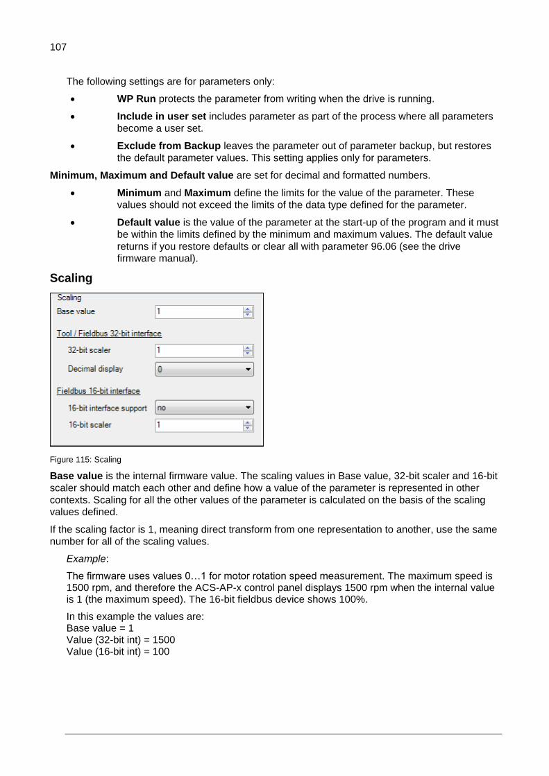
107
The following settings are for parameters only:
WP Run protects the parameter from writing when the drive is running.
Include in user set includes parameter as part of the process where all parameters
become a user set.
Exclude from Backup leaves the parameter out of parameter backup, but restores
the default parameter values. This setting applies only for parameters.
Minimum, Maximum and Default value are set for decimal and formatted numbers.
Minimum and Maximum define the limits for the value of the parameter. These
values should not exceed the limits of the data type defined for the parameter.
Default value is the value of the parameter at the start-up of the program and it must
be within the limits defined by the minimum and maximum values. The default value
returns if you restore defaults or clear all with parameter 96.06 (see the drive
firmware manual).
Scaling
Figure 115: Scaling
Base value is the internal firmware value. The scaling values in Base value, 32-bit scaler and 16-bit
scaler should match each other and define how a value of the parameter is represented in other
contexts. Scaling for all the other values of the parameter is calculated on the basis of the scaling
values defined.
If the scaling factor is 1, meaning direct transform from one representation to another, use the same
number for all of the scaling values.
Example:
The firmware uses values 0…1 for motor rotation speed measurement. The maximum speed is 1500 rpm, and therefore the ACS-AP-x control panel displays 1500 rpm when the internal value is 1 (the maximum speed). The 16-bit fieldbus device shows 100%.
In this example the values are: Base value = 1 Value (32-bit int) = 1500 Value (16-bit int) = 100
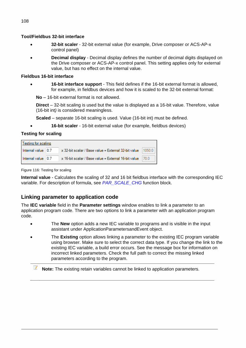
108
Tool/Fieldbus 32-bit interface
32-bit scaler - 32-bit external value (for example, Drive composer or ACS-AP-x
control panel)
Decimal display - Decimal display defines the number of decimal digits displayed on
the Drive composer or ACS-AP-x control panel. This setting applies only for external
value, but has no effect on the internal value.
Fieldbus 16-bit interface
16-bit interface support - This field defines if the 16-bit external format is allowed,
for example, in fieldbus devices and how it is scaled to the 32-bit external format:
No – 16-bit external format is not allowed.
Direct – 32-bit scaling is used but the value is displayed as a 16-bit value. Therefore, value (16-bit int) is considered meaningless.
Scaled – separate 16-bit scaling is used. Value (16-bit int) must be defined.
16-bit scaler - 16-bit external value (for example, fieldbus devices)
Testing for scaling
Figure 116: Testing for scaling
Internal value - Calculates the scaling of 32 and 16 bit fieldbus interface with the corresponding IEC
variable. For description of formula, see PAR_SCALE_CHG function block.
Linking parameter to application code
The IEC variable field in the Parameter settings window enables to link a parameter to an
application program code. There are two options to link a parameter with an application program
code.
The New option adds a new IEC variable to programs and is visible in the input
assistant under ApplicationParametersandEvent object.
The Existing option allows linking a parameter to the existing IEC program variable
using browser. Make sure to select the correct data type. If you change the link to the
existing IEC variable, a build error occurs. See the message box for information on
incorrect linked parameters. Check the full path to correct the missing linked
parameters according to the program.
Note: The existing retain variables cannot be linked to application parameters.

109
Parameter types
In the Parameter Settings window, you can select the Parameter Type for the newly created
parameter.
Figure 117: Parameter type
Decimal number creates a parameter with actual numeric contents, either decimal or non-decimal
numbers. The available IEC types are REAL, UDINT, UINT, DINT and INT.
Formatted number parameter type is used to make special purpose parameters like date displays,
version texts, passcodes, and so on. The available IEC types are UDINT, UINT, DINT and INT. In
the Display format for Data Parameter, you can define the format in which the value should be
displayed in the Drive composer or ACS-AP-x control panel.
Figure 118: Display format for data parameter

110
Bit pointer creates a pointer parameter which can be assigned to point to a bit of another parameter. You must associate the bit pointer parameter to a selection list (a bit pointer list) that must be created beforehand. For more information, see section Selection lists. The only available IEC type for bit pointer is BOOL. You can define the default selection from the list.
Figure 119: Selection list
Value pointer creates a pointer parameter which can be assigned to point to another parameter.
You must associate the value pointer parameter to a selection list (a value pointer list). For more
information, see section Selection lists. The only available IEC type for the value pointer is UDINT.
You can define the default selection from the list.
Plain value list must be associated to a selection list (a plain value list) and it allows only values of
the list as its own value. The available IEC types are UDINT, UINT, DINT and INT. You can define
the default selection from the list.
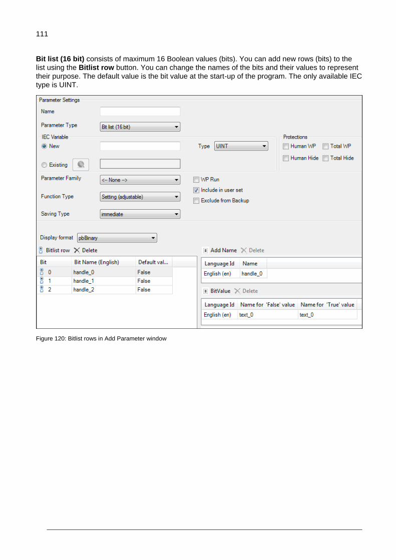
111
Bit list (16 bit) consists of maximum 16 Boolean values (bits). You can add new rows (bits) to the
list using the Bitlist row button. You can change the names of the bits and their values to represent
their purpose. The default value is the bit value at the start-up of the program. The only available IEC
type is UINT.
Figure 120: Bitlist rows in Add Parameter window

112
Parameter families
If a parameter shares some of its attributes (scaling, minimum/maximum, and so on) with another
parameter, it can belong to a family that describes these common attributes. This way, when the
attribute is changed in one parameter, it is also changed in all parameters belonging to the same
family. The system library includes a function block to modify parameter attributes like
PAR_UNIT_SEL functions. See AY1LB_System_ACS880_V3_5 library in Appendix C: ABB drives
system library.
If you select a parameter family Version style, make sure the family has a unique Name. The
parameter families can define limit or scaling properties or both of them.
Figure 121: Parameter families
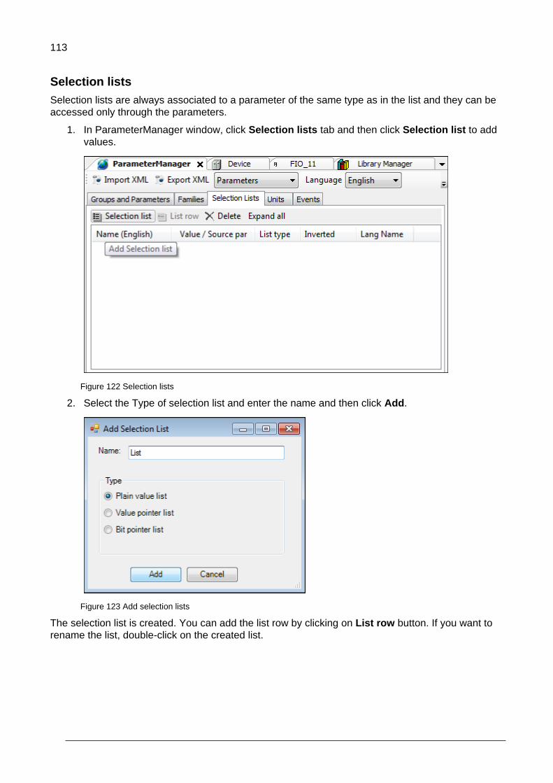
113
Selection lists
Selection lists are always associated to a parameter of the same type as in the list and they can be
accessed only through the parameters.
1. In ParameterManager window, click Selection lists tab and then click Selection list to add
values.
Figure 122 Selection lists
2. Select the Type of selection list and enter the name and then click Add.
Figure 123 Add selection lists
The selection list is created. You can add the list row by clicking on List row button. If you want to
rename the list, double-click on the created list.
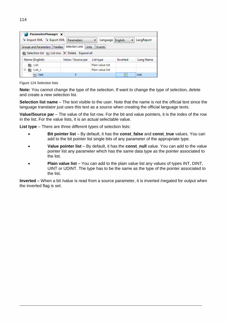
114
Figure 124 Selection lists
Note: You cannot change the type of the selection. If want to change the type of selection, delete
and create a new selection list.
Selection list name – The text visible to the user. Note that the name is not the official text since the
language translator just uses this text as a source when creating the official language texts.
Value/Source par – The value of the list row. For the bit and value pointers, it is the index of the row
in the list. For the value lists, it is an actual selectable value.
List type – There are three different types of selection lists:
Bit pointer list – By default, it has the const_false and const_true values. You can
add to the bit pointer list single bits of any parameter of the appropriate type.
Value pointer list – By default, it has the const_null value. You can add to the value
pointer list any parameter which has the same data type as the pointer associated to
the list.
Plain value list – You can add to the plain value list any values of types INT, DINT,
UINT or UDINT. The type has to be the same as the type of the pointer associated to
the list.
Inverted – When a bit /value is read from a source parameter, it is inverted /negated for output when
the inverted flag is set.

115
Units
You can create own units for the application parameters. A unit has a unique number and a name.
The allowed unit codes for the application program are 128…255.
You can add translations of the name into other languages.
1. In the ParameterManager view, click Units tab.
Figure 125 Unit
2. Click New Unit to add unit and click Add to add Language Id.
Figure 126 Units and translations
The units are attached to parameters in the Add Parameter options in Parameter Settings window.

116
Application events
You can configure your own application events (faults or warnings). The application program then
triggers the event and the event registers in the drive event logger with a time stamp. This tool
defines the event ID code, type and event name (with translation).
In the ParameterManager view, click Events tab and then click Event to add Event.
Figure 127 Events
Events dialog box gives the following information:
Name, in this example Event_1. The Event name is displayed on the ACS-AP-x control panel
and in the Drive composer tools when the event is activated / deactivated.
Event Type, in this example fault.
The following event types are supported:
1 = Fault (Trips the drive.)
2 = Warning (Is registered to the event logger.)
3 = Pure event (Is registered to another logger.)
Event ID, in this example E100. Each type of event has its numerical range (ID code). You can
select the ID code within the range.
The event is activated by using the EVENT function block in the program code (library
AY1LB_System_ACS880_V3_5, see chapter Libraries ). Every event must have its own instance of
the EVENT block. The EVENT function block must have the same ID code and type as defined in
the previous dialog box.

117
Configuring extension I/O modules
Contents of this chapter
This chapter contains general information on how to configure F-Series extension I/O in drive
application programming through Automation Builder programming tool.
Configuring extension I/O module
FEA-03
The FEA-03 F-series Extension adapter is used to locate additive F-series modules like FIO-01, FIO-
11 or FAIO-01 modules. The FEA-03 module contains 2-slots with 2-switches each. You can add
FIO-01, FIO-11 or FAIO-01 modules to the slots of the control board or FEA-03 module. The
application programming supports 7-extension I/O modules. See parameter group 14 I/O extension
module 1 in ACS880 primary control program firmware manual [3AUA0000085967 (English)].
For example, the below figure illustrates the maximum configuration of FSeries modules on the
Control board (ZCU) and FEA-03 adapters supported by ACS880. It contains 3-firmware and 7-
program modules. Node numbers 1, 2, 3 are on control board slot 1, 2, 3 and the remaining node
numbers are FEA-modules and their node numbers are defined by F-Series module switch.
8
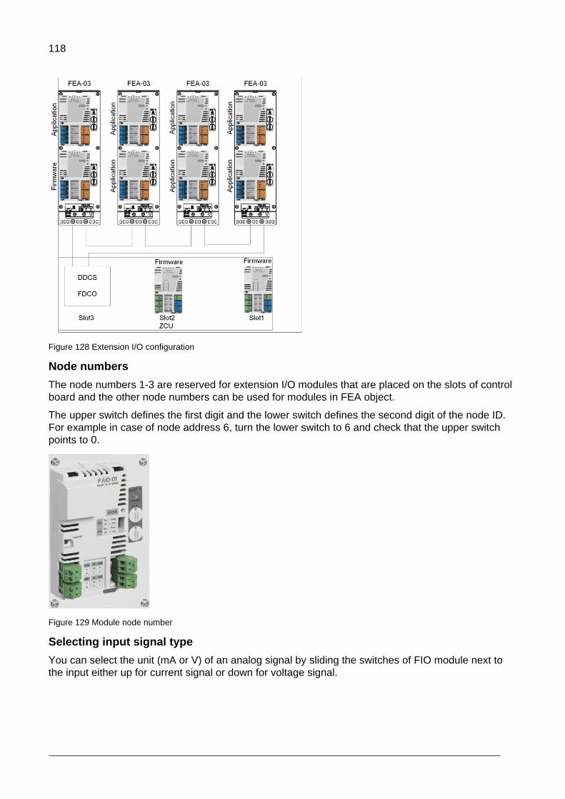
118
Figure 128 Extension I/O configuration
Node numbers
The node numbers 1-3 are reserved for extension I/O modules that are placed on the slots of control
board and the other node numbers can be used for modules in FEA object.
The upper switch defines the first digit and the lower switch defines the second digit of the node ID.
For example in case of node address 6, turn the lower switch to 6 and check that the upper switch
points to 0.
Figure 129 Module node number
Selecting input signal type
You can select the unit (mA or V) of an analog signal by sliding the switches of FIO module next to
the input either up for current signal or down for voltage signal.

119
Current signal Voltage signal
Figure 130 FIO module

120
FDCO
In FDCO adapter, select the channel number based on the used slot. Communication slot for FDCO
adapter is defined by parameter 60.41 Extension adapter com port based on the used slot and
channel. For the descriptions of parameter, see ACS880 primary control program firmware manual
[3AUA0000085967 (English)].
For example, if FDCO adapter is placed on slot 2 and channel A is used, slot2 A is selected for Extension adapter com port. For further details, see FDCO-01/02 DDCS communication modules user’s manual [3AUA0000114058 (English)].
1 Connector for channel A
2 Connector for channel B
3 Selector for channel A
4 Selector for channel B
5 Lock
6 Mounting screw
7 LEDs
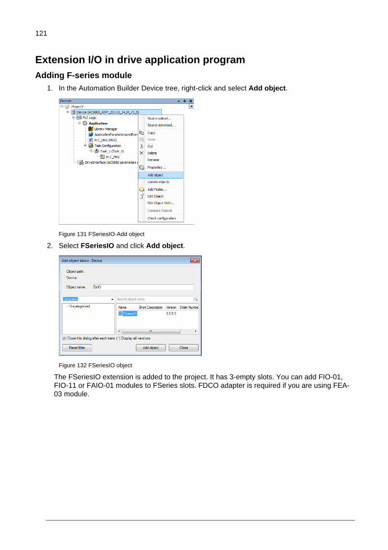
121
Extension I/O in drive application program
Adding F-series module
1. In the Automation Builder Device tree, right-click and select Add object.
Figure 131 FSeriesIO-Add object
2. Select FSeriesIO and click Add object.
Figure 132 FSeriesIO object
The FSeriesIO extension is added to the project. It has 3-empty slots. You can add FIO-01,
FIO-11 or FAIO-01 modules to FSeries slots. FDCO adapter is required if you are using FEA-
03 module.

122
Figure 133 FSeriesIO slots
Note: You can add only one FDCO adapter to FSeriesIO extension. Because it has only one
communication port for FDCO adapter in the firmware. See parameter 60.41 Extension
adapter com port in ACS880 primary control program firmware manual [3AUA0000085967
(English)].
3. In the ExtIO (FSeriesIO), right-click on empty slot and click Add object.
Figure 134 Emptyslot 1 - Add object
4. Select FDCO-01/02 adapter and click Replace object.
Figure 135 FDCO-01/02
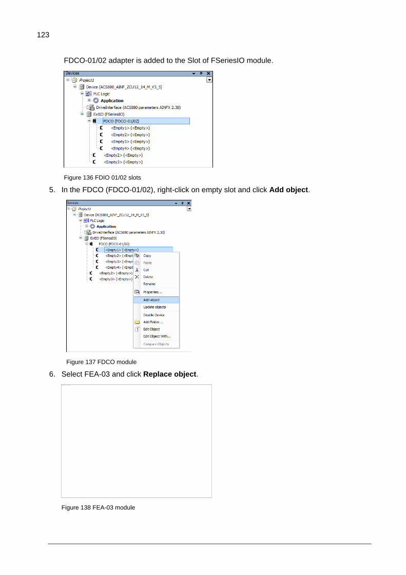
123
FDCO-01/02 adapter is added to the Slot of FSeriesIO module.
Figure 136 FDIO 01/02 slots
5. In the FDCO (FDCO-01/02), right-click on empty slot and click Add object.
Figure 137 FDCO module
6. Select FEA-03 and click Replace object.
Figure 138 FEA-03 module

124
7. In the FEA (FEA-03) module, right-click on an empty slot and click Add object.
Figure 139 FEA-03 add object
8. Select FIO-01 module and click Replace object.
Figure 140 FIO-01 module
Similarly, you can add FIO-11 or FAIO-01 modules to FEA-03 empty slots.

125
Setting module data
Adding node number
1. In the Automation Builder, double-click FIO_01 or any other module.
2. Click I/O-Bus Module Parameters tab and add the node number in the value field.
Figure 141 Node number
The node numbers 1, 2 or 3 are based on slot numbers. The node numbers 4-10 are used if
the I/O module is placed on FEA-03 module.
I/O mapping variabes
1. In the Automation Builder, double-click FIO-01 or any other module.
2. Click I/O-Bus Module I/O Mapping tab and create I/O mapping variables in Variable column.
Figure 142 I/O mapping variables
The variable names must be individual. You can have maximum 100 mapping variables. I/O
mapping variables do not support Mapping to existing variables.

126
FIO-01 Module data
You can find the general information of FIO-01 module by clicking on Information tab.
Figure 143 FIO-01 information
FIO-01 Channel descriptions
Channel Descriptions
Status 0 = Not active
1 = Initializing state
2 = Active
3 = No communication
Control 0 = Inactivate
1 = Activate FIO-01module
DIOx_FilterTime Defines the filtering time constant (0.8…100.0ms). This time is applied for all
filtered inputs (optional).
DIOx_ChDir (x=1-4) 0 = DIO is used as a digital output (default value).
1 = DIO is used as a digital input.

127
DIOx_Output (x=1-4) 1/0 = ON/OFF status of digital output if channel is used as output (ChDir = 0).
The corresponding ON and OFF time delays are applied if they are defined.
DIOx_ONDelay (x=1-4) Defines activation delay (0.0…300.0s) applied for digital input/output. This
channel is optional.
DIOx_OFFDelay(x=1-4)
Defines deactivation delay (0.0…300.0s) applied for digital input/output. This
channel is optional.
DIOx_FiltInput (x=1-4) 1/0 = ON/OFF status of digital input if channel is used as input (ChDir = 1).
Filter time is applied if it is defined. Time delays are never applied.
DIOx_Input (x=1-4) 1/0 = ON/OFF status of digital input if channel is used as input (ChDir = 1).
The corresponding ON and OFF time delays are applied if they are defined.
ROx_Output (x=1-2)
1 = Relay is energized (ON).
0 = Relay is de-energized (OFF).
ROx_ONDelay (x=1-2)
Defines activation delay (0.0…300.0s) applied for delayed state (optional).
ROx_OFFDelay (x=1-2)
Defines deactivation delay (0.0…300.0s) applied for delayed state (optional).
ROx_DelayState (x=1-2) 1/0 = ON/OFF status of relay.
The corresponding ON and OFF time delays are applied if they are defined.

128
FIO-11 Module data
You can find the general information of FIO-11 module by clicking on Information tab.
Figure 144 FIO-11 General information
FIO-11 Channel descriptions
Channel Description
Status 0 = Not active
1 = Initializing state
2 = Active
3 = No communication
Control 0 = Inactivate
1 = Activates FIO-11 module
DIOx_FilterTime Defines the filtering time constant (0.8…100.0ms). This time is applied for all
filtered inputs (optional).

129
DIOx_ChDir (x=1,2) 0 = DIO is used as a digital output (default value).
1 = DIO is used as a digital input.
DIOx_Output (x=1,2) 1/0 = ON/OFF status of digital output if the channel is used as a output (ChDir
= 0).
The corresponding ON and OFF time delays are applied if they are defined.
DIOx_ONDelay (x=1,2)
Defines activation delay (0.0…300.0s) applied for digital input/output. This
channel is optional.
DIOx_OFFDelay(x=1,2)
Defines deactivation delay (0.0…300.0s) applied for digital input/output. This
channel is optional.
DIOx_FiltInput (x=1,2) 1/0 = ON/OFF status of digital input if the channel is used as a input (ChDir =
1).
Filter time is applied if it is defined. Time delays are never applied.
DIOx_Input (x=1,2)
1/0 = ON/OFF status of digital input if the channel is used as a input (ChDir =
1).
The corresponding ON and OFF time delays are applied if they are defined.
AOx_ForceSel 1 = A forced value is applied for an analog output (optional for testing
purposes).
0 = Forcing is not in use.
AO1_FiltTime
Defines the filter time constant (0.000…30.000s).
This time is applied for the filtered analog output. This channel is optional.
AO1_FiltMin
Defines the minimum output value for an analog output (0.000...22.000mA).
AO1_FiltMax
Defines the maximum output value for an analog output (0.000...22.000mA).
AO1_FiltMinScaled
Defines the real value (-32768.0…32767.0) that corresponds to the minimum
output value (AO1_FiltMin). The source value is defined in AO1_ScaledOut.
AO1_FiltMaxScaled
Defines the real value (-32768.0…32767.0) that corresponds to the maximum
output value (AO1_FiltMax). The source value is defined in AO1_ScaledOut.
AO1_ScaledOut Defines the output source value.
AO1_ForceData
Defines the forced value that can be used instead of the output source value
AO1_ScaledOut. This channel is optional.
The forced value (0.000...22.000mA) is applied for AO1_Actual without
checking the minimum or maximum output values. Filter time is not applied.

130
AO1_Actual
The actual analog output value (0.000...22.000mA).
The value is same as in AO1_Filtered if forcing in not in use.
AO1_Filtered
The filtered and scaled analog output value (0.000...22.000mA).
AIx_ForceSel 0 = Forcing is not in use (optional for testing purposes).
1 = Force AI1 to a value of AI1_ForceData.
2 = Force AI2 to a value of AI2_ForceData.
3 = Force AI1 to a value of AI1_ForceData and AI2 to a value of
AI2_ForceData.
4 = Force AI3 to a value of AI3_ForceData.
5 = Force AI1 to a value of AI1_ForceData and AI3 to a value of
AI3_ForceData.
6 = Force AI2 to a value of AI2_ForceData and AI3 to a value of
AI3_ForceData.
7 = Force AI1 to a value of AI1_ForceData, AI2 to value a of AI2_ForceData
and AI3 to value of AI3_ForceData.
AIx_Unit (x=1-3)
Unit selection. This setting must match the corresponding hardware setting on
the I/O extension module.
2 = V (Volts)
10 = mA (milliamperes)
AIx_Min (x=1-3)
Defines the minimum value for an analog input (-22.000...22.000mA or V).
AIx_Max (x=1-3)
Defines the maximum value for an analog input (-22.000...22.000mA or V).
AIx_MinScaled (x=1-3)
Defines the real value (-32768.0…32767.0) that corresponds to the minimum
analog input value (AIx_Min).
AIx_MaxScaled (x=1-3)
Defines the real value (-32768.0…32767.0) that corresponds to the maximum
analog input value (AIx_Max).
AIx_FiltTime (x=1-3)
Defines the filter time constant for the analog input (0.000…30.000s).
This time is applied for analog inputs AIx_Actual and AIx_Scaled. This channel
is optional.
AIx_FiltGain (x=1-3)
Selects the hardware filtering time for analog input. This channel is optional.
(0 = no filtering, 1 = 125 us, 2 = 250 us, 3 = 500 us, 4 = 1 ms, 5 = 2 ms, 6 =
4ms, 7 = 7,9375 ms).
AIx_ForceData (x=1-3) Defines the forced value that can be used instead of the true reading of input.
This channel is optional.
The forced value (-22.000...22.000mA or V) is applied for AIx_Actual without
checking minimum or maximum values. Filter time is not applied.
AIx_Actual (x=1-3) Displays the value of an analog input (-22.000...22.000mA or V).

131
AIx_Scaled (x=1-3) Displays the value of an analog input (-22.000...22.000mA or V) after scaling.
AIx_Switch (x=1-3) 0 = Unit selection matches the corresponding hardware setting.
1 = Unit selection does not match the corresponding hardware setting.
FAIO-01 Module data
You can find the general information of FAIO-01 module by clicking on Information tab.
Figure 145 FAIO-01 General information
FAIO-01 Channel descriptions
Channel Description
Status 0 = Not active
1 = Initializing state
2 = Active (successfully activated by Control)
3 = No communication
Control 0 = Inactivate
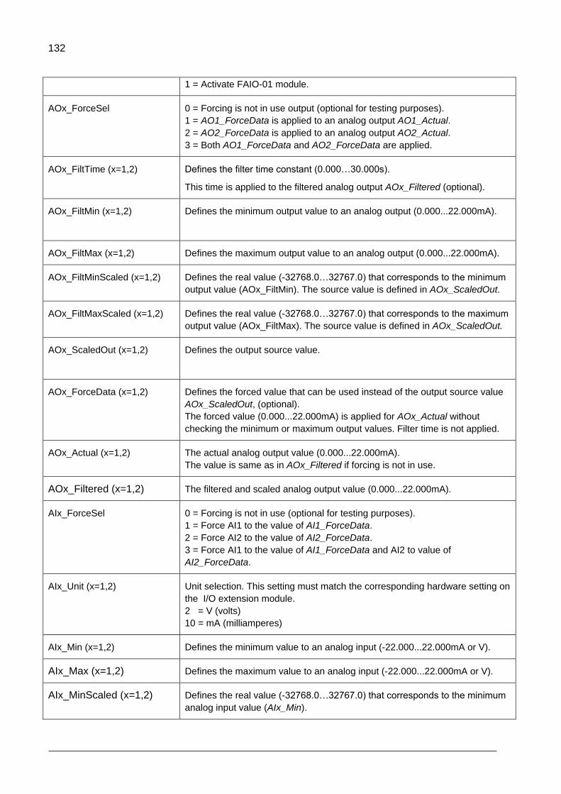
132
1 = Activate FAIO-01 module.
AOx_ForceSel 0 = Forcing is not in use output (optional for testing purposes).
1 = AO1_ForceData is applied to an analog output AO1_Actual.
2 = AO2_ForceData is applied to an analog output AO2_Actual.
3 = Both AO1_ForceData and AO2_ForceData are applied.
AOx_FiltTime (x=1,2) Defines the filter time constant (0.000…30.000s).
This time is applied to the filtered analog output AOx_Filtered (optional).
AOx_FiltMin (x=1,2)
Defines the minimum output value to an analog output (0.000...22.000mA).
AOx_FiltMax (x=1,2) Defines the maximum output value to an analog output (0.000...22.000mA).
AOx_FiltMinScaled (x=1,2)
Defines the real value (-32768.0…32767.0) that corresponds to the minimum
output value (AOx_FiltMin). The source value is defined in AOx_ScaledOut.
AOx_FiltMaxScaled (x=1,2)
Defines the real value (-32768.0…32767.0) that corresponds to the maximum
output value (AOx_FiltMax). The source value is defined in AOx_ScaledOut.
AOx_ScaledOut (x=1,2)
Defines the output source value.
AOx_ForceData (x=1,2) Defines the forced value that can be used instead of the output source value
AOx_ScaledOut, (optional).
The forced value (0.000...22.000mA) is applied for AOx_Actual without
checking the minimum or maximum output values. Filter time is not applied.
AOx_Actual (x=1,2) The actual analog output value (0.000...22.000mA).
The value is same as in AOx_Filtered if forcing is not in use.
AOx_Filtered (x=1,2) The filtered and scaled analog output value (0.000...22.000mA).
AIx_ForceSel 0 = Forcing is not in use (optional for testing purposes).
1 = Force AI1 to the value of AI1_ForceData.
2 = Force AI2 to the value of AI2_ForceData.
3 = Force AI1 to the value of AI1_ForceData and AI2 to value of
AI2_ForceData.
AIx_Unit (x=1,2) Unit selection. This setting must match the corresponding hardware setting on
the I/O extension module.
2 = V (volts)
10 = mA (milliamperes)
AIx_Min (x=1,2) Defines the minimum value to an analog input (-22.000...22.000mA or V).
AIx_Max (x=1,2) Defines the maximum value to an analog input (-22.000...22.000mA or V).
AIx_MinScaled (x=1,2) Defines the real value (-32768.0…32767.0) that corresponds to the minimum
analog input value (AIx_Min).
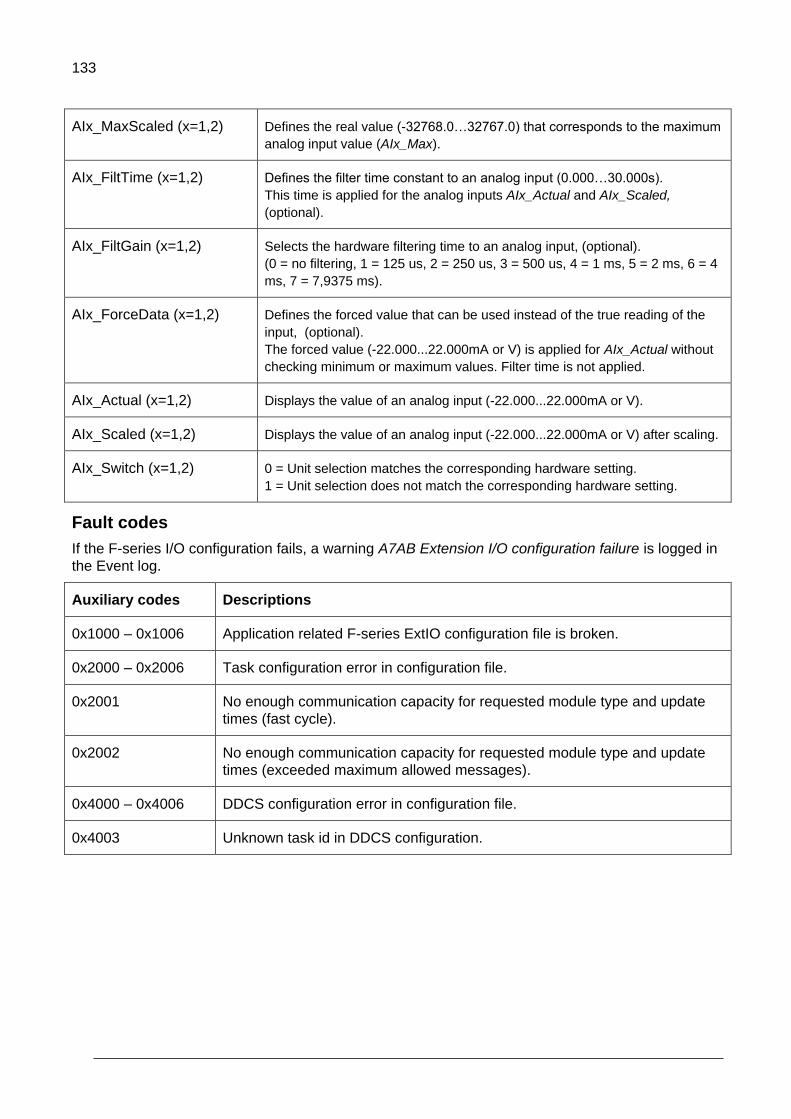
133
AIx_MaxScaled (x=1,2) Defines the real value (-32768.0…32767.0) that corresponds to the maximum
analog input value (AIx_Max).
AIx_FiltTime (x=1,2) Defines the filter time constant to an analog input (0.000…30.000s).
This time is applied for the analog inputs AIx_Actual and AIx_Scaled,
(optional).
AIx_FiltGain (x=1,2) Selects the hardware filtering time to an analog input, (optional).
(0 = no filtering, 1 = 125 us, 2 = 250 us, 3 = 500 us, 4 = 1 ms, 5 = 2 ms, 6 = 4
ms, 7 = 7,9375 ms).
AIx_ForceData (x=1,2) Defines the forced value that can be used instead of the true reading of the
input, (optional).
The forced value (-22.000...22.000mA or V) is applied for AIx_Actual without
checking minimum or maximum values. Filter time is not applied.
AIx_Actual (x=1,2) Displays the value of an analog input (-22.000...22.000mA or V).
AIx_Scaled (x=1,2) Displays the value of an analog input (-22.000...22.000mA or V) after scaling.
AIx_Switch (x=1,2) 0 = Unit selection matches the corresponding hardware setting.
1 = Unit selection does not match the corresponding hardware setting.
Fault codes
If the F-series I/O configuration fails, a warning A7AB Extension I/O configuration failure is logged in
the Event log.
Auxiliary codes Descriptions
0x1000 – 0x1006 Application related F-series ExtIO configuration file is broken.
0x2000 – 0x2006 Task configuration error in configuration file.
0x2001 No enough communication capacity for requested module type and update
times (fast cycle).
0x2002 No enough communication capacity for requested module type and update
times (exceeded maximum allowed messages).
0x4000 – 0x4006 DDCS configuration error in configuration file.
0x4003 Unknown task id in DDCS configuration.
134
Libraries
Contents of this chapter
This chapter contains general information of libraries and description of the ABB drives system and
standard libraries. You can find more detailed information in Appendix C: ABB drives system library
and Appendix E: ABB drives standard library.
Library types
The following libraries are installed by default in Automation Builder for drive programming.
Default libraries:
ABB drives system library (AY1LB_System_ACS880_V3_5)
ABB drives standard library (AS1LB_Standard_ACS880_V3_5).
Optional libraries:
All generic Automation Builder IEC libraries (standard and util) can be installed, but
ABB does not guarantee their correct functioning. Note the data type limitations
described in Data types).
9

135
The Library Manager controls and manages the library usage in the project. Each project has its own
Library Manager which is added by default when you create a new project.
Figure 146: Library Manager
ABB drives standard library contains the most common and useful functions and function blocks
for drive control. All the functions are implemented locally using structured text language. The
automation builder and standard libraries include additional general purpose functions.
ABB drives system library includes all the drive-specific functions to interface the application with
the drive firmware and I/O interface. This library has external implementation in the drive system
software.
Note: Make sure the drive has the corresponding system library installed:
1. In the Drive composer pro System info, select More in Products.
2. Check that the Application System Library displayed in the Drive composer pro has the
same library version as the Automation Builder project. If the versions are not
matching, part of the library may be incompatible.
Adding a library to the project
To add a Library Manager (library container) to the project:
1. In the Devices tree, right-click Application and select Add object.
2. In the Add object window, select Library Manager and click Add object.
3. Double-click Library Manager. Library Manager window is displayed.
Figure 147: Library manager
4. Click Add library to add library.

136
5. In the Add Library window, click Advanced.
Figure 148 Advanced option
6. Select the required library and click OK.
Figure 149: Add library

137
The selected library is added successfully.
Figure 150: New library added in Library Manager
Note: To make SFC language programs or functions, the IeCSfc system library must be
available in the project.
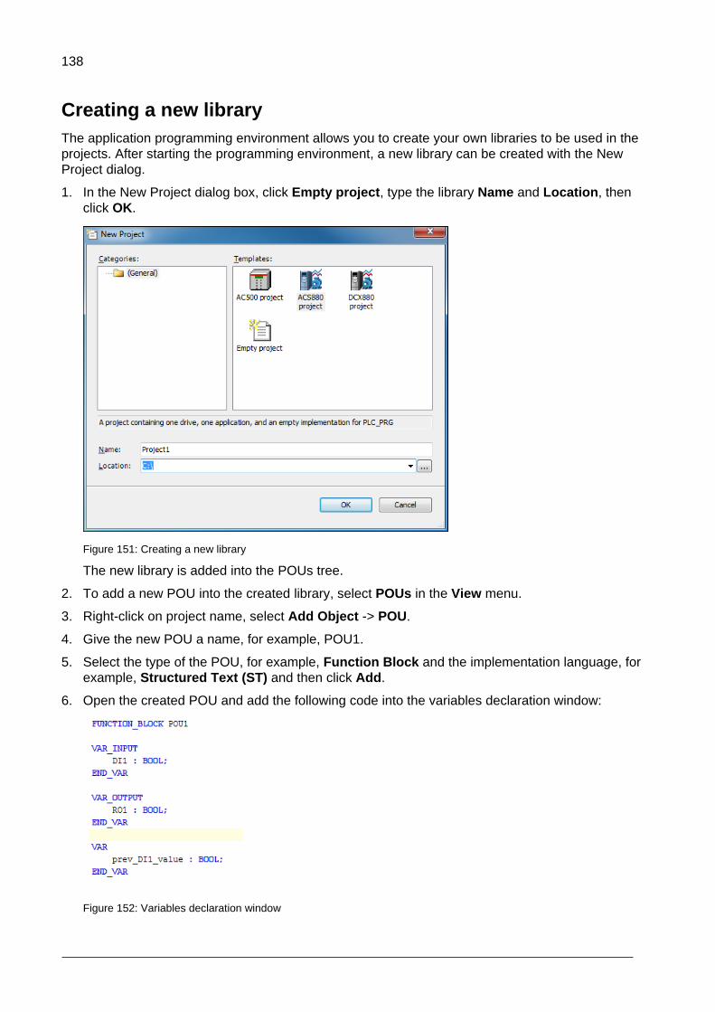
138
Creating a new library
The application programming environment allows you to create your own libraries to be used in the
projects. After starting the programming environment, a new library can be created with the New
Project dialog.
1. In the New Project dialog box, click Empty project, type the library Name and Location, then
click OK.
Figure 151: Creating a new library
The new library is added into the POUs tree.
2. To add a new POU into the created library, select POUs in the View menu.
3. Right-click on project name, select Add Object -> POU.
4. Give the new POU a name, for example, POU1.
5. Select the type of the POU, for example, Function Block and the implementation language, for
example, Structured Text (ST) and then click Add.
6. Open the created POU and add the following code into the variables declaration window:
Figure 152: Variables declaration window
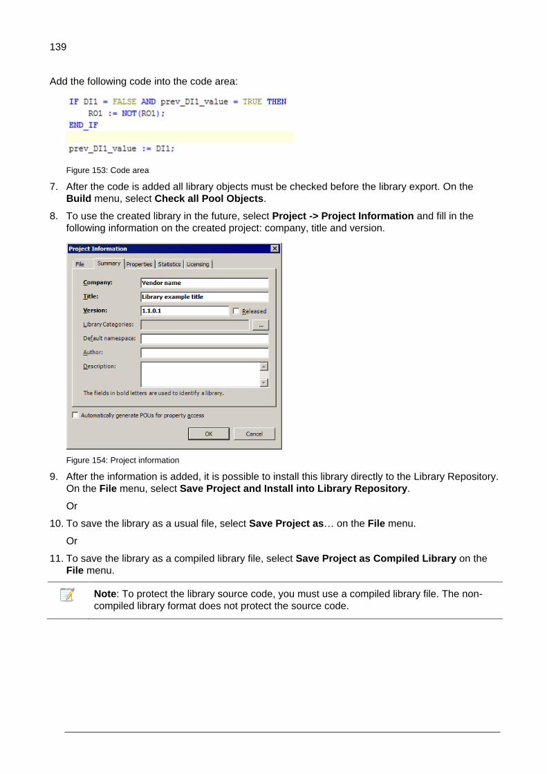
139
Add the following code into the code area:
Figure 153: Code area
7. After the code is added all library objects must be checked before the library export. On the
Build menu, select Check all Pool Objects.
8. To use the created library in the future, select Project -> Project Information and fill in the
following information on the created project: company, title and version.
Figure 154: Project information
9. After the information is added, it is possible to install this library directly to the Library Repository.
On the File menu, select Save Project and Install into Library Repository.
Or
10. To save the library as a usual file, select Save Project as… on the File menu.
Or
11. To save the library as a compiled library file, select Save Project as Compiled Library on the
File menu.
Note: To protect the library source code, you must use a compiled library file. The non-
compiled library format does not protect the source code.

140
Installing a new library
If the needed library is not in the repository, it must be installed before use.
To install a new library, follow these steps:
1. Open Library Manager and click Add library.
2. In the Add Library window, click Advanced.
3. Click Library Repository.
Figure 155 Library repository

141
4. In the Library Repository window, click Install.
Figure 156 Installing library
5. Browse/select the required compiled library and click Open.
A new library is installed into the Library Repository and is ready for use in the project.

142
Managing library versions
Automation Builder allows you to use different versions of the selected library according to project
requirements.
To change the current effective library version:
1. Open Library Manager.
2. Select the required library and click the Properties.
Figure 157 Library manager properties
3. Select the Specific version in the drop-down list and click OK.
Figure 158: System library version
The library version is changed and can be used in the project.
If you want to add a new library version that is not in the Specific version list, install the
version first. See section Installing a new library.

143
Practical examples and tips
Contents of this chapter
This chapter gives practical examples and tips on working with Automation Builder.
Solving communication problems
Follow the instructions when the scan network does not find any drives.
a. Check the communication settings.
b. In Windows Computer Management -> Device Manager, check that your communication
port is correctly installed.
c. If the USB Serial Port (COMX) is not displayed under Device Manager, check that the
corresponding USB/communication port driver is installed.
Figure 159: Checking communication port installation
10

144
d. To check that the OPC server (DriveDA.exe) has started in Windows Task Manager, select
Ctrl + shift + esc -> Processes.
Figure 160: Checking OPC server in Windows task manager
e. Check that Drive composer pro (Drive OPC) finds the connection to the drive.
Note: You must allow Automation Builder to share communication with Drive composer pro.
To work in parallel with Drive composer pro, you must do the register setting of DriveDA OPC server. This register setting is not included in the installation setup of Automation builder version 1.2.2.
For details on how to allow Automation Builder to share communication with Drive composer pro, see chapter Setting up the programming environment.
The reinstallation of the Drive composer pro adds a new InprocServer object to the registry.
Figure 161: Registry
Follow the instructions when the communication fails while establishing online connection to the
drive.
a. Check the Firewall settings in your PC that may block connections to devices. ABB
Automation Builder needs port 1217 for connecting to the gateway.
b. If multiple nodes are displayed, it can mean that ProxyRTS is started twice or that the IP address is not set as localhost (should not be possible to change).
To resolve this proxy issue, follow these steps: i. In Windows task manager, close DriveDA.exe. ii. From the Online menu in Automation Builder, select Restart ProxyRTS.

145
Figure 162: Restart ProxyRTS
Follow the instructions when the communication fails between Automation Builder/Drive composer
pro and drive.
Check the control panel version to be newer than the version in the below screen.
1.
Figure 163: Control panel driver details
Check the Driver date.
Note: The next panel driver version is not known. For version details, refer the
corresponding ACS880 drive software release notes or contact your ABB representative.
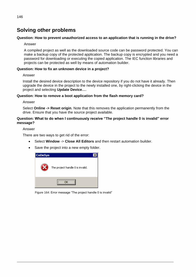
146
Solving other problems
Question: How to prevent unauthorized access to an application that is running in the drive?
Answer
A compiled project as well as the downloaded source code can be password protected. You can make a backup copy of the protected application. The backup copy is encrypted and you need a password for downloading or executing the copied application. The IEC function libraries and projects can be protected as well by means of automation builder.
Question: How to fix an unknown device in a project?
Answer
Install the desired device description to the device repository if you do not have it already. Then upgrade the device in the project to the newly installed one, by right-clicking the device in the project and selecting Update Device….
Question: How to remove a boot application from the flash memory card?
Answer
Select Online -> Reset origin. Note that this removes the application permanently from the drive. Ensure that you have the source project available.
Question: What to do when I continuously receive “The project handle 0 is invalid” error
message?
Answer
There are two ways to get rid of the error:
Select Window -> Close All Editors and then restart automation builder.
Save the project into a new empty folder.
Figure 164: Error message “The project handle 0 is invalid”

147
Question: What to do when stack overflow fault 6487 occurs?
If stack overflow fault 6487 occurs, the number of the local variables inside a function is
too large. Unfortunately the limit of the local variables is relatively small. The stack usage
is high especially if there are, for example, division operands inside the EXPT function.
Also if the division function’s divider is zero (an exceptional case), the stack usage is
high.
Answer
Do not make big functions. Try to make a compact function with a limited number of the variables (40 REAL). If the function is too large, change some of the local variables to global variables (use, for example, multiple global variable lists GVL to group variables by functions). Consider to use function blocks or program modules instead of functions.
Question: How to optimize the memory usage of the drive application?
The code memory of the application is running out. How to optimize the program?
Answer
The drive application programming environment has relatively limited memory and execution capacity. There are a couple of tips to minimize the program code:
Use functions as much as possible.
Note: If there are many variables inside the function, the risk of stack overflow
increases.
Try to design the application so that you do not need to create many instances of big
function blocks. Instead of function blocks use programs or functions.
Use DriveInterface to access drive parameters instead of the parameter read / write
functions
Question: How to solve the problem causing error message “Creating boot application failed:
Adding Application Parameters & Groups to UFF generator: XmlDeserializationFailed”?
Answer
This problem is related to Application parameters and events module
Check that all Value pointer, Bit pointer and Plain value list type of parameters have the
correct Selection List.
Check that the Bit list (16 bit) parameters do not have same Bit names (English) multiple
times (for example, text Bit_Handle_0 occurs twice).
Check the tool message box for details.
148
Appendix A: Incompatible features between ACS880 Drive and AC500 PLC IEC programming
Contents of this chapter
This chapter lists the features that are not compatible between ACS880 Drive and AC500 PLC IEC
programming V3 and V2.3.
Incompatible features
Unlike the newer V3, V2.3 does not allow functions to have multiple outputs, thus the
VAR_OUTPUT or VAR_IN_OUT tags cannot be included in the description part of
functions. Converting the function into a function block solves this issue and provides
an identical interface on both platforms at the cost of additional memory usage.
Single-line comments “//” are not supported in V2.3. Use block comments instead
“(*…*)”.
Array initialization has different syntax. For this reason, it is not possible to have code
that initializes an array to non-default values at declaration that is suitable for both
versions. This can be solved by writing values to the array once right after the code is
called.
Boolean operations are not allowed for integer types other than BYTE, WORD and
DWORD in V2.3.
Namespaces are not supported in V2.3.
At least one statement is required for IF, ELSEIF and ELSE instructions in V2.3.
11
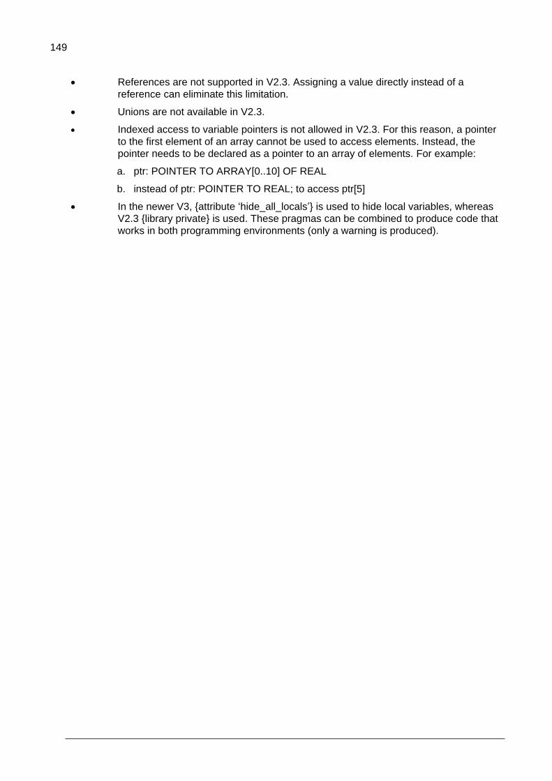
149
References are not supported in V2.3. Assigning a value directly instead of a
reference can eliminate this limitation.
Unions are not available in V2.3.
Indexed access to variable pointers is not allowed in V2.3. For this reason, a pointer
to the first element of an array cannot be used to access elements. Instead, the
pointer needs to be declared as a pointer to an array of elements. For example:
a. ptr: POINTER TO ARRAY[0..10] OF REAL
b. instead of ptr: POINTER TO REAL; to access ptr[5]
In the newer V3, {attribute ‘hide_all_locals’} is used to hide local variables, whereas
V2.3 {library private} is used. These pragmas can be combined to produce code that
works in both programming environments (only a warning is produced).

150
Appendix B: Unsupported features
The ACS880 and DCX880 drives do not support the following standard IEC programming V3
features:
Persistent variable type is not supported. In case the variable is saved over power
cycle, retain variable is used. Also, user defined drive parameter can be created to
save value of the variable.
Target-based tracing. You can use the Monitor feature in Drive composer pro. See
Drive composer user’s manual (3AUA0000094606 [English]).
Some data types are not supported.
The number of program execution tasks are limited to 4. One of the task is a pre task
which is executed only once after power up. Other tasks are cyclically executed.
Program code simulation is not supported.
Target based visualization is not supported.
12

151
Appendix C: ABB drives system library
Contents of this chapter
This appendix contains detailed information of the function blocks of the ABB drives system library
(AS1LB_Standard_ACS880_V3_5)
Introduction to ABB drives system library
The ABB drives system library is intended to be used with the ACS880 drives. It provides event,
parameter read/write and program time level function blocks for application programming in the
automation builder environment. The description of the features in this document is based on the
ABB drives system library version 1.9.1.0.
Note: Using the Drive composer pro System info, check that the drive has the corresponding system
library installed. In the System info, the system library version is located under the Products/ More
view. The system library versions must be the same in the drive and the application program project.
13
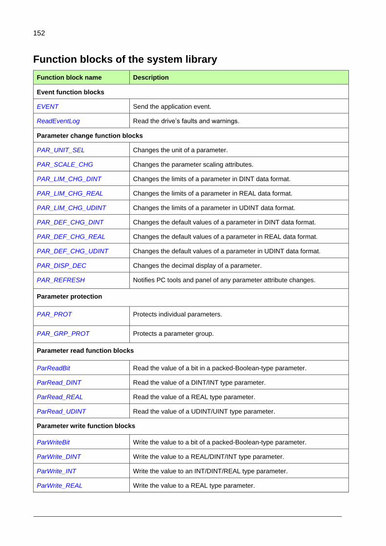
152
Function blocks of the system library
Function block name Description
Event function blocks
EVENT Send the application event.
ReadEventLog Read the drive’s faults and warnings.
Parameter change function blocks
PAR_UNIT_SEL Changes the unit of a parameter.
PAR_SCALE_CHG Changes the parameter scaling attributes.
PAR_LIM_CHG_DINT Changes the limits of a parameter in DINT data format.
PAR_LIM_CHG_REAL Changes the limits of a parameter in REAL data format.
PAR_LIM_CHG_UDINT Changes the limits of a parameter in UDINT data format.
PAR_DEF_CHG_DINT Changes the default values of a parameter in DINT data format.
PAR_DEF_CHG_REAL Changes the default values of a parameter in REAL data format.
PAR_DEF_CHG_UDINT Changes the default values of a parameter in UDINT data format.
PAR_DISP_DEC Changes the decimal display of a parameter.
PAR_REFRESH Notifies PC tools and panel of any parameter attribute changes.
Parameter protection
PAR_PROT Protects individual parameters.
PAR_GRP_PROT Protects a parameter group.
Parameter read function blocks
ParReadBit Read the value of a bit in a packed-Boolean-type parameter.
ParRead_DINT Read the value of a DINT/INT type parameter.
ParRead_REAL Read the value of a REAL type parameter.
ParRead_UDINT Read the value of a UDINT/UINT type parameter.
Parameter write function blocks
ParWriteBit Write the value to a bit of a packed-Boolean-type parameter.
ParWrite_DINT Write the value to a REAL/DINT/INT type parameter.
ParWrite_INT Write the value to an INT/DINT/REAL type parameter.
ParWrite_REAL Write the value to a REAL type parameter.

153
Function block name Description
ParWrite_UDINT Write the value to an UDINT/UINT type parameter.
Pointer parameter read function blocks
ParRead_BitPTR Read the pointed bit value from a bit pointer type parameter.
ParRead_INT
ParRead_INT reads the value of a INT/DINT/REAL type of parameter.
ParRead_ValPTR_DINT Read the pointed DINT/INT value from a value pointer type parameter.
ParRead_ValPTR_REAL Read the pointed REAL value from a value pointer type parameter.
ParRead_ValPTR_UDINT Read the pointed UDINT/UINT value from a value pointer type parameter.
Set pointer parameter function blocks
ParSet_BitPTR_IEC Set a bit pointer parameter to point to a bit type IEC variable.
ParSet_ValPTR_IEC_DINT Set a value pointer parameter to point to a DINT type IEC variable.
ParSet_ValPTR_IEC_REAL Set a value pointer parameter to point to a REAL type IEC variable.
ParSet_ValPTR_IEC_UDINT Set a value pointer parameter to point to an UDINT type IEC variable.
ParSet_BitPTR_Par Set a bit pointer parameter to point to a bit of a packed Boolean parameter.
ParSet_ValPTR_Par Set a value pointer parameter to point to a value parameter.
Task time level function block
UsedTimeLevel Show time level (ms) of the program where the function block is located.

154
Event function blocks
EVENT
Summary
The application event function block is used to trigger a predefined event
(fault/warning/pure) from the IEC code. The event is registered to drive
event logger.
Connections
Inputs
Name Type Value Description
ID WORD 0xE100.. 0xE2FF Identification of the event (constant, cannot be changed on run time). This is a unique value of the event. You can find the supported values in the ApplicationParametersAndEvent tool. A certain range is reserved for each application event type.
Faults:
0xE100…E1FF
Warnings:
0xE200.. 0xE2FF
AuxCode DWORD ANY The auxiliary code that you can set freely (constant).
EventType WORD 1,2 Type of the event (constant, cannot be changed on run time). Supported event types: Fault = 1, Warning = 2, Pure = 8 (Notice is not supported).
Trig BOOL T/F The high level (TRUE) of this pin sends/activates the event, if Enable is set to TRUE. Warning is deactivated automatically, when Trig falls down. To clear the fault, give the reset command.
Enable BOOL T/F Enable/disable event sending.
Outputs
Name Type Value Description
Err WORD ANY The value is typically 0x0000.
0x0001 = Not used 0x0002 = Event is not user-defined event 0x0003 = Event type error 0x0004 = Event ID type error 0x0005 = Not used 0x0006 = Unknown event type
Description
You can configure an application event with the ApplicationParametersandEvents in Automation
Builder tool. (See Application parameter and event creation). This tool defines the ID and the event
text (description).
Automation Builder supports the following event types: Fault, Warning and Pure.

155
The event ID, text, auxiliary code, time and operation data is registered into the drive event logger.
The application events can be shown using the ACS-AP-x control panel and Drive composer tools,
or using the ReadEventLog block on the application level. A fault can be reset, for example, using
the control panel or Drive composer pro tool.
Note: The current firmware supports execution of three event functions in the same task cycle. If there are more event functions, do not enable all of them at the same time.
ReadEventLog
Summary
ReadEventLog is a special block for reading faults and warnings
from the drive event system. The block does not read events or
use the drive event or fault loggers. Instead it gets the events
straight from the event system itself.
The purpose of the block is to forward drive events, for example,
to external systems, like automation user interfaces.
Inputs
Name Type Value Description
EventType UINT 0 Not used. The block returns the drive’s faults and warnings. Can be set to 0.
Index UINT 0 Not used. Can be set to 0.
Cnt UINT 0…6 Number of the wanted events at a time. ( 0…6 )
Enable BOOL T/F Enable / disable the block execution. The falling edge of this pin clears all the output vectors.
Outputs
Name Type Value Description
Err UINT N/A Not used.
Code Array of UINT[10]
Any of allowed events codes
Event code (ID). The block supports maximum 6 events at a time.
AuxCode Array of UINT[10]
ANY Auxiliary code of the event.
Status Array of UINT[10]
ANY Status of the event.
1 = The event has been activated. 2 = The event has been deactivated. 3 = Acknowledgement requested. 4 = The event is reactivated (warnings). 5 = All faults have been deactivated.
RdCnt UINT 0…6 The number of the get/read events at a time.
Maximum 6
RdCnt value = 0 indicates that there are no new
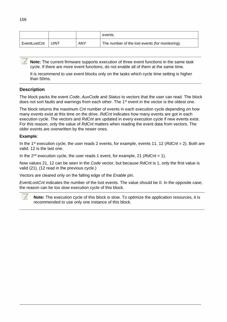
156
events.
EventLostCnt UINT ANY The number of the lost events (for monitoring).
Note: The current firmware supports execution of three event functions in the same task cycle. If there are more event functions, do not enable all of them at the same time.
It is recommend to use event blocks only on the tasks which cycle time setting is higher than 50ms.
Description
The block packs the event Code, AuxCode and Status to vectors that the user can read. The block
does not sort faults and warnings from each other. The 1st event in the vector is the oldest one.
The block returns the maximum Cnt number of events in each execution cycle depending on how
many events exist at this time on the drive. RdCnt indicates how many events are got in each
execution cycle. The vectors and RdCnt are updated in every execution cycle if new events exist.
For this reason, only the value of RdCnt matters when reading the event data from vectors. The
older events are overwritten by the newer ones.
Example:
In the 1st execution cycle, the user reads 2 events, for example, events 11, 12 (RdCnt = 2). Both are
valid. 12 is the last one.
In the 2nd execution cycle, the user reads 1 event, for example, 21 (RdCnt = 1).
Now values 21, 12 can be seen in the Code vector, but because RdCnt is 1, only the first value is
valid (21). (12 read in the previous cycle.)
Vectors are cleared only on the falling edge of the Enable pin.
EventLostCnt indicates the number of the lost events. The value should be 0. In the opposite case,
the reason can be too slow execution cycle of this block.
Note: The execution cycle of this block is slow. To optimize the application resources, it is recommended to use only one instance of this block.
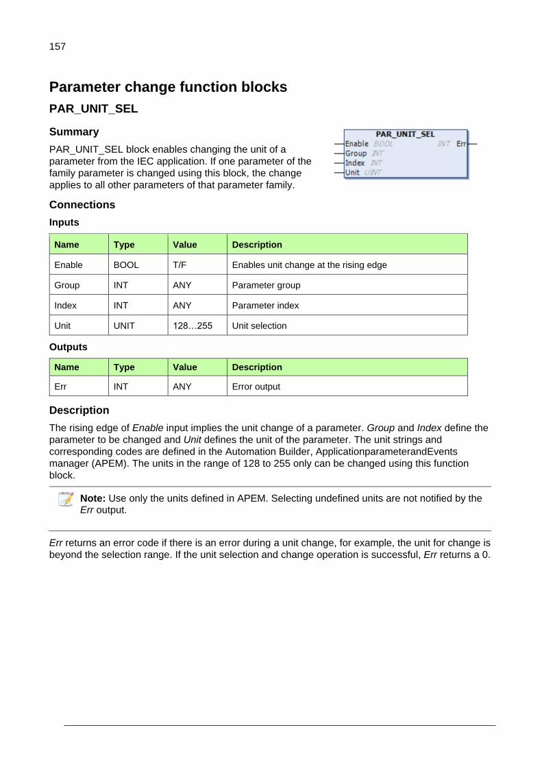
157
Parameter change function blocks
PAR_UNIT_SEL
Summary
PAR_UNIT_SEL block enables changing the unit of a
parameter from the IEC application. If one parameter of the
family parameter is changed using this block, the change
applies to all other parameters of that parameter family.
Connections
Inputs
Name Type Value Description
Enable BOOL T/F Enables unit change at the rising edge
Group INT ANY Parameter group
Index INT ANY Parameter index
Unit UNIT 128…255 Unit selection
Outputs
Name Type Value Description
Err INT ANY Error output
Description
The rising edge of Enable input implies the unit change of a parameter. Group and Index define the
parameter to be changed and Unit defines the unit of the parameter. The unit strings and
corresponding codes are defined in the Automation Builder, ApplicationparameterandEvents
manager (APEM). The units in the range of 128 to 255 only can be changed using this function
block.
Note: Use only the units defined in APEM. Selecting undefined units are not notified by the Err output.
Err returns an error code if there is an error during a unit change, for example, the unit for change is
beyond the selection range. If the unit selection and change operation is successful, Err returns a 0.

158
PAR_SCALE_CHG
Summary
PAR_SCALE_CHG block enables changing the
parameter scaling attributes from the IEC
application. Initial scaling values are defined in the
Parameter family settings.
Connections
Inputs
Name Type Value Description
Enable BOOL T/F Enables scale change at the rising edge
Group INT ANY Parameter group
Index INT ANY Parameter index
Basevalue DINT 128…255 Scales internal value to external 32 or 16 bit interface. Used as divider.
BIT32_scaler DINT ANY Scaling factor for external 32 bit interface in panel (ACS-AP-I), DriveComposer and fieldbus interface. The value is used as a multiplayer.
BIT16_scaler INT ANY Scaling factor for external 16 bit interface for fieldbus interface. The value is used as a multiplayer.
Outputs
Name Type Value Description
Err INT ANY Error output
Description
This function block enables changing the parameter scaling factor that scales the internal value for
DriveComposer-tool, ACS-AP-I panel and fieldbus interface. The initial values of the scaling factors
are defined in ApplicationparameterandEvents manager (APEM) for all user parameters. The
changed parameter scaling applies to all parameters of a specific family (scaling) defined in APEM.
The rising edge of Enable input implies the parameter scaling change. Group and Index define the
parameter to be changed. The Basevalue scales the internal value to external 32 or 16 bit interface.
The BIT32_scaler and BIT16_scaler are used as scaling interfaces.
The Err output returns an error code if there is an error during the scaling change operation. If the
scaling changes are successful, Err returns a 0.
External 32-bit scaling
This is used by (ACS-AP-I), Drive Composer and PLC over fieldbus adapter. If the parameter type is
REAL, the number of decimals influence the scaling defined in ApplicationparametersandEvents
manager or the PAR_DISP_DEC block.
If external value is requested as 32-bit integer, the internal float is scaled to external float with the
same scaling factor and then converted to 32 bit integer with extra numbers for decimal values,

159
depending on the display format of decimals. For example: The value 1.23456 is displayed as 1.235
if the display format is 3 decimals.
Scaling formula:
𝐸𝑥𝑡𝑒𝑟𝑛𝑎𝑙_𝑣𝑎𝑙𝑢𝑒(32 𝑏𝑖𝑡) =𝐵𝐼𝑇32_𝑠𝑐𝑎𝑙𝑒𝑟×10(𝐷𝑒𝑐𝑖𝑚𝑎𝑙𝑠)
𝐵𝑎𝑠𝑒𝑣𝑎𝑙𝑢𝑒× 𝐼𝐸𝐶_𝑝𝑟𝑜𝑔𝑟𝑎𝑚_𝑣𝑎𝑟𝑖𝑎𝑏𝑙𝑒(𝑖𝑛𝑡𝑒𝑟𝑛𝑎𝑙 𝑣𝑎𝑙𝑢𝑒)
External 16-bit scaling
This scaling is used only for fieldbus interface to fit internal value with higher number of bits to the 16
bit scale. The 16 bit external value uses its own scaling factor with no display format for decimals.
Scaling formula:
𝐸𝑥𝑡𝑒𝑟𝑛𝑎𝑙_𝑣𝑎𝑙𝑢𝑒(16 𝑏𝑖𝑡) =𝐵𝐼𝑇16_𝑠𝑐𝑎𝑙𝑒𝑟
𝐵𝑎𝑠𝑒𝑣𝑎𝑙𝑢𝑒× 𝐼𝐸𝐶_𝑝𝑟𝑜𝑔𝑟𝑎𝑚_𝑣𝑎𝑟𝑖𝑎𝑏𝑙𝑒(𝑖𝑛𝑡𝑒𝑟𝑛𝑎𝑙 𝑣𝑎𝑙𝑢𝑒)

160
Parameter limit change
PAR_LIM_CHG_DINT
Summary
The PAR_LIM_CHG_DINT block enables changing the
minimum and maximum values (in DINT data format) of a
parameter from the IEC application. The changes in the limit
values apply to all parameters belonging to same parameter
family defined in APEM.
Connections
Inputs
Name Type Value Description
Enable BOOL T/F Enables changing parameter limits at the rising edge
Group INT ANY Parameter group
Index INT ANY Parameter index
Min_Val DINT ANY New minimum value in DINT data format
Max_Val DINT ANY New maximum value in DINT data format
Outputs
Name Type Value Description
Err INT ANY Error output
Description
The rising edge of Enable input implies the changed parameter limit values. Group and Index define
the parameter to be changed. The Min_Val and Max_Val are used to set the new minimum and
maximum values of the parameter respectively.
Note: Ensure the following conditions while defining the minimum and maximum values:
The Min_Val must be greater than Max_Val.
The Max_Val must be lesser than Min_Val.
Min_Val should not be equal to Max_Val.
Err returns an error code if there is an error during the limits changes operation, for example, the
new limits are beyond the range. If the change operation is successful, Err returns a 0.

161
PAR_LIM_CHG_REAL
Summary
The PAR_LIM_CHG_REAL block enables changing the
minimum and maximum values (in REAL data format) of the
parameter from the IEC application. The changes in the limit
values apply to all parameters belonging to same parameter
family defined in APEM.
Connections
Inputs
Name Type Value Description
Enable BOOL T/F Enables changing parameter limits at the rising edge
Group INT ANY Parameter group
Index INT ANY Parameter index
Min_Val REAL ANY New minimum value in REAL data format
Max_Val REAL ANY New maximum value in REAL data format
Outputs
Name Type Value Description
Err INT ANY Error output
Description
The rising edge of Enable input implies the changed parameter limit values. Group and Index define
the parameter to be changed. The Min_Val and Max_Val are used to set the new minimum and
maximum values of the parameter respectively.
Note: Ensure the following conditions while defining the minimum and maximum values:
The Min_Val must be greater than Max_Val.
The Max_Val must be lesser than Min_Val.
Min_Val should not be equal to Max_Val.
Err returns an error code if there is an error during the limits changes operation, for example, the
new limits are beyond the range. If the change operation is successful, Err returns a 0.

162
PAR_LIM_CHG_UDINT
Summary
The PAR_LIM_CHG_UDINT block enables changing the
minimum and maximum values (in UDINT data format) of a
parameter from the IEC application. The changes in the limit
values apply to all parameters belonging to same parameter
family defined in APEM.
Connections
Inputs
Name Type Value Description
Enable BOOL T/F Enables changing parameter limits at the rising edge
Group INT ANY Parameter group
Index INT ANY Parameter index
Min_Val UDINT ANY New minimum value in UDINT data format
Max_Val UDINT ANY New maximum value in UDINT data format
Outputs
Name Type Value Description
Err INT ANY Error output
Description
The rising edge of Enable input implies the changed parameter limit values. Group and Index define
the parameter to be changed. The Min_Val and Max_Val are used to set the new minimum and
maximum values of the parameter respectively.
Note: Ensure the following conditions while defining the minimum and maximum values:
The Min_Val must be greater than Max_Val.
The Max_Val must be lesser than Min_Val.
Min_Val should not be equal to Max_Val.
Err returns an error code if there is an error during the limits changes operation, for example, the
new limits are beyond the range. If the change operation is successful, Err returns a 0.
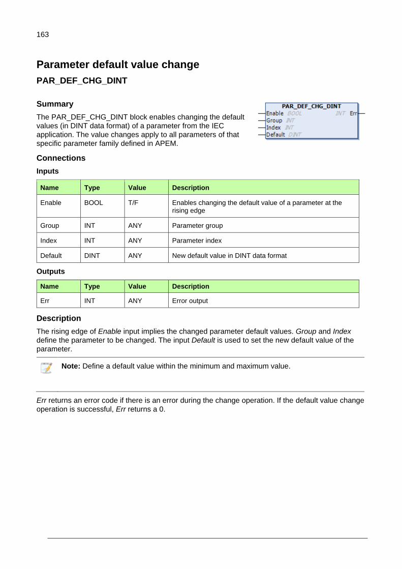
163
Parameter default value change
PAR_DEF_CHG_DINT
Summary
The PAR_DEF_CHG_DINT block enables changing the default
values (in DINT data format) of a parameter from the IEC
application. The value changes apply to all parameters of that
specific parameter family defined in APEM.
Connections
Inputs
Name Type Value Description
Enable BOOL T/F Enables changing the default value of a parameter at the rising edge
Group INT ANY Parameter group
Index INT ANY Parameter index
Default DINT ANY New default value in DINT data format
Outputs
Name Type Value Description
Err INT ANY Error output
Description
The rising edge of Enable input implies the changed parameter default values. Group and Index
define the parameter to be changed. The input Default is used to set the new default value of the
parameter.
Note: Define a default value within the minimum and maximum value.
Err returns an error code if there is an error during the change operation. If the default value change
operation is successful, Err returns a 0.
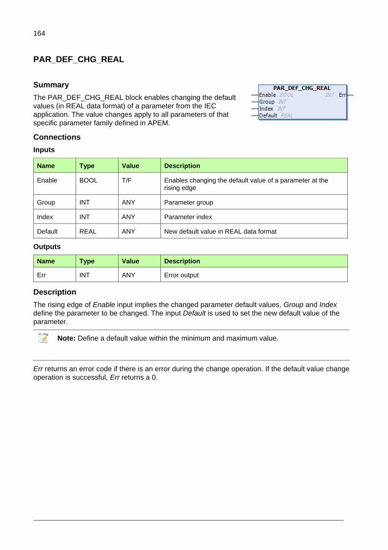
164
PAR_DEF_CHG_REAL
Summary
The PAR_DEF_CHG_REAL block enables changing the default
values (in REAL data format) of a parameter from the IEC
application. The value changes apply to all parameters of that
specific parameter family defined in APEM.
Connections
Inputs
Name Type Value Description
Enable BOOL T/F Enables changing the default value of a parameter at the rising edge
Group INT ANY Parameter group
Index INT ANY Parameter index
Default REAL ANY New default value in REAL data format
Outputs
Name Type Value Description
Err INT ANY Error output
Description
The rising edge of Enable input implies the changed parameter default values. Group and Index
define the parameter to be changed. The input Default is used to set the new default value of the
parameter.
Note: Define a default value within the minimum and maximum value.
Err returns an error code if there is an error during the change operation. If the default value change
operation is successful, Err returns a 0.

165
PAR_DEF_CHG_UDINT
Summary
The PAR_DEF_CHG_UDINT block enables changing the
default values (in UDINT data format) of a parameter from the
IEC application. The value changes apply to all parameters of
that specific parameter family defined in APEM.
Connections
Inputs
Name Type Value Description
Enable BOOL T/F Enables changing the default value of a parameter at the rising edge
Group INT ANY Parameter group
Index INT ANY Parameter index
Default UDINT ANY New default value in UDINT data format
Outputs
Name Type Value Description
Err INT ANY Error output
Description
The rising edge of Enable input implies the changed parameter default values. Group and Index
define the parameter to be changed. The input Default is used to set the new default value of the
parameter.
Note: Define a default value within the minimum and maximum value.
Err returns an error code if there is an error during the change operation. If the default value change
operation is successful, Err returns a 0.

166
Parameter decimal display
PAR_DISP_DEC
Summary
PAR_DISP_DEC block enables changing the number of
displayed decimals of a parameter from the IEC
application. If one parameter of the family parameter is
changed using this block, the change applies to all other
parameters of that parameter family.
Connections
Inputs
Name Type Value Description
Enable BOOL T/F Enables decimal display change at the rising edge
Group INT ANY Parameter group
Index INT ANY Parameter index
Decimals UNIT 128…255 Number of decimals to display
Outputs
Name Type Value Description
Err INT ANY Error output
Description
The rising edge of Enable input implies the decimal display change of a parameter. Group and Index define the parameter to be changed and the input Decimals defines the number of decimal values to display. If the parameter is in REAL data format, the value is scaled for fieldbus interface by scaling factor 10(decimals).
Err returns an error code if there is an error during a unit change, for example, the unit for change is
beyond the selection range. If the unit selection and change operation is successful, Err returns a 0.
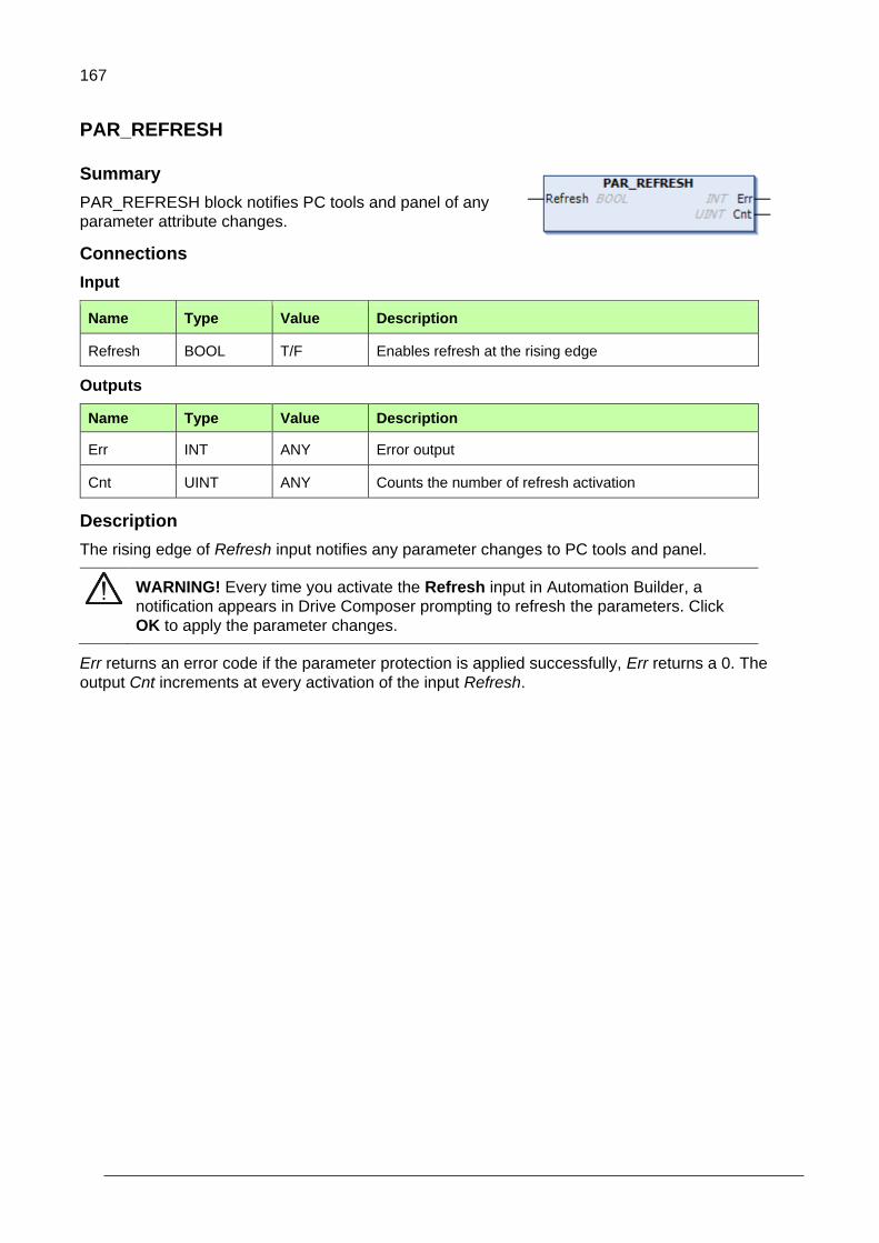
167
PAR_REFRESH
Summary
PAR_REFRESH block notifies PC tools and panel of any
parameter attribute changes.
Connections
Input
Name Type Value Description
Refresh BOOL T/F Enables refresh at the rising edge
Outputs
Name Type Value Description
Err INT ANY Error output
Cnt UINT ANY Counts the number of refresh activation
Description
The rising edge of Refresh input notifies any parameter changes to PC tools and panel.
WARNING! Every time you activate the Refresh input in Automation Builder, a
notification appears in Drive Composer prompting to refresh the parameters. Click
OK to apply the parameter changes.
Err returns an error code if the parameter protection is applied successfully, Err returns a 0. The
output Cnt increments at every activation of the input Refresh.
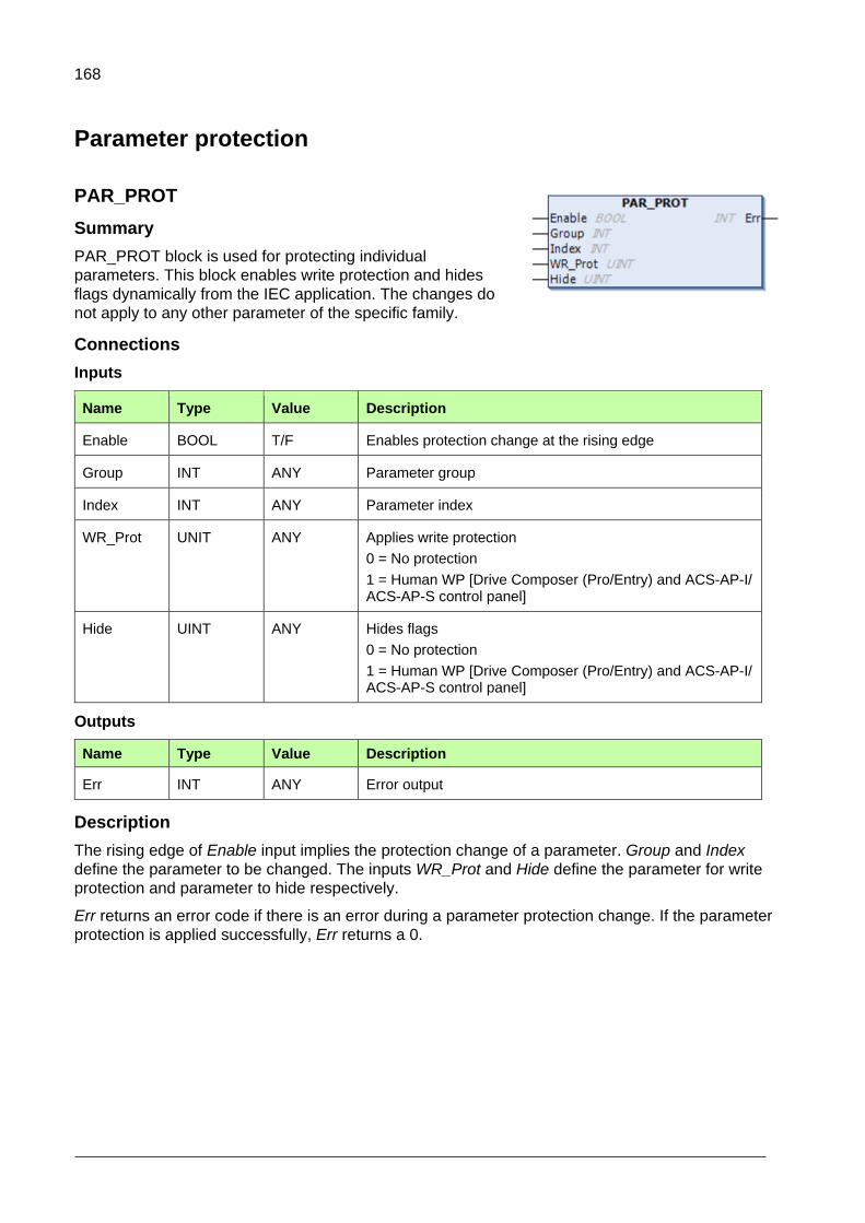
168
Parameter protection
PAR_PROT
Summary
PAR_PROT block is used for protecting individual
parameters. This block enables write protection and hides
flags dynamically from the IEC application. The changes do
not apply to any other parameter of the specific family.
Connections
Inputs
Name Type Value Description
Enable BOOL T/F Enables protection change at the rising edge
Group INT ANY Parameter group
Index INT ANY Parameter index
WR_Prot UNIT ANY Applies write protection
0 = No protection
1 = Human WP [Drive Composer (Pro/Entry) and ACS-AP-I/ ACS-AP-S control panel]
Hide UINT ANY Hides flags
0 = No protection
1 = Human WP [Drive Composer (Pro/Entry) and ACS-AP-I/ ACS-AP-S control panel]
Outputs
Name Type Value Description
Err INT ANY Error output
Description
The rising edge of Enable input implies the protection change of a parameter. Group and Index
define the parameter to be changed. The inputs WR_Prot and Hide define the parameter for write
protection and parameter to hide respectively.
Err returns an error code if there is an error during a parameter protection change. If the parameter
protection is applied successfully, Err returns a 0.
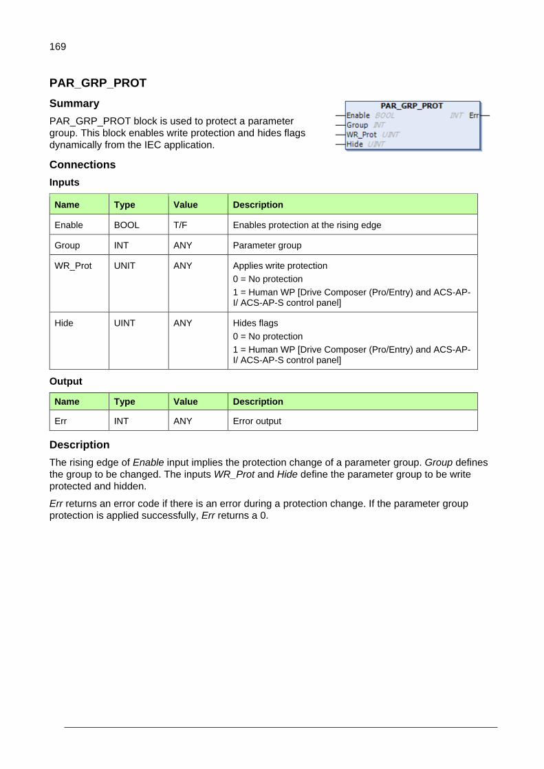
169
PAR_GRP_PROT
Summary
PAR_GRP_PROT block is used to protect a parameter
group. This block enables write protection and hides flags
dynamically from the IEC application.
Connections
Inputs
Name Type Value Description
Enable BOOL T/F Enables protection at the rising edge
Group INT ANY Parameter group
WR_Prot UNIT ANY Applies write protection
0 = No protection
1 = Human WP [Drive Composer (Pro/Entry) and ACS-AP-I/ ACS-AP-S control panel]
Hide UINT ANY Hides flags
0 = No protection
1 = Human WP [Drive Composer (Pro/Entry) and ACS-AP-I/ ACS-AP-S control panel]
Output
Name Type Value Description
Err INT ANY Error output
Description
The rising edge of Enable input implies the protection change of a parameter group. Group defines
the group to be changed. The inputs WR_Prot and Hide define the parameter group to be write
protected and hidden.
Err returns an error code if there is an error during a protection change. If the parameter group
protection is applied successfully, Err returns a 0.
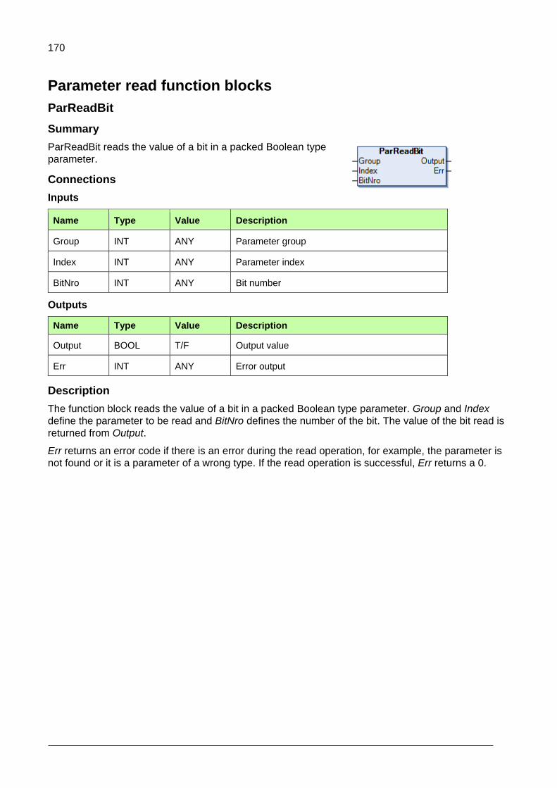
170
Parameter read function blocks
ParReadBit
Summary
ParReadBit reads the value of a bit in a packed Boolean type
parameter.
Connections
Inputs
Name Type Value Description
Group INT ANY Parameter group
Index INT ANY Parameter index
BitNro INT ANY Bit number
Outputs
Name Type Value Description
Output BOOL T/F Output value
Err INT ANY Error output
Description
The function block reads the value of a bit in a packed Boolean type parameter. Group and Index
define the parameter to be read and BitNro defines the number of the bit. The value of the bit read is
returned from Output.
Err returns an error code if there is an error during the read operation, for example, the parameter is
not found or it is a parameter of a wrong type. If the read operation is successful, Err returns a 0.
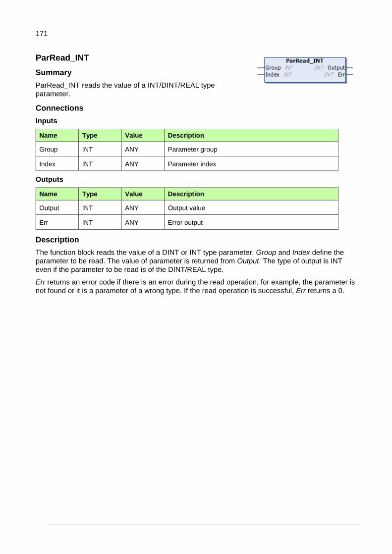
171
ParRead_INT
Summary
ParRead_INT reads the value of a INT/DINT/REAL type
parameter.
Connections
Inputs
Name Type Value Description
Group INT ANY Parameter group
Index INT ANY Parameter index
Outputs
Name Type Value Description
Output INT ANY Output value
Err INT ANY Error output
Description
The function block reads the value of a DINT or INT type parameter. Group and Index define the
parameter to be read. The value of parameter is returned from Output. The type of output is INT
even if the parameter to be read is of the DINT/REAL type.
Err returns an error code if there is an error during the read operation, for example, the parameter is
not found or it is a parameter of a wrong type. If the read operation is successful, Err returns a 0.
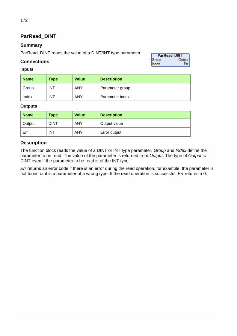
172
ParRead_DINT
Summary
ParRead_DINT reads the value of a DINT/INT type parameter.
Connections
Inputs
Name Type Value Description
Group INT ANY Parameter group
Index INT ANY Parameter index
Outputs
Name Type Value Description
Output DINT ANY Output value
Err INT ANY Error output
Description
The function block reads the value of a DINT or INT type parameter. Group and Index define the
parameter to be read. The value of the parameter is returned from Output. The type of Output is
DINT even if the parameter to be read is of the INT type.
Err returns an error code if there is an error during the read operation, for example, the parameter is
not found or it is a parameter of a wrong type. If the read operation is successful, Err returns a 0.
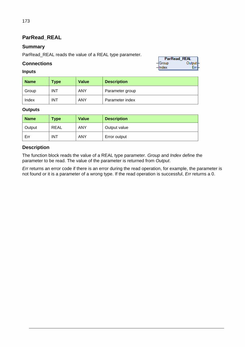
173
ParRead_REAL
Summary
ParRead_REAL reads the value of a REAL type parameter.
Connections
Inputs
Name Type Value Description
Group INT ANY Parameter group
Index INT ANY Parameter index
Outputs
Name Type Value Description
Output REAL ANY Output value
Err INT ANY Error output
Description
The function block reads the value of a REAL type parameter. Group and Index define the
parameter to be read. The value of the parameter is returned from Output.
Err returns an error code if there is an error during the read operation, for example, the parameter is
not found or it is a parameter of a wrong type. If the read operation is successful, Err returns a 0.

174
ParRead_UDINT
Summary
ParRead_UDINT reads the value of a UDINT/UINT type
parameter.
Connections
Inputs
Name Type Value Description
Group INT ANY Parameter group
Index INT ANY Parameter index
Outputs
Name Type Value Description
Output UDINT ANY Output value
Err INT ANY Error output
Description
The function block reads the value of a UDINT or UINT type parameter. Group and Index define the
parameter to be read. The value of the parameter is returned from Output. The type of the output is
UDINT even if the parameter to be read is of the UINT type.
Err returns an error code if there is an error during the read operation, for example, the parameter is
not found or it is a parameter of a wrong type. If the read operation is successful, Err returns a 0.

175
Parameter write function blocks
ParWriteBit
Summary
ParWriteBit writes a value to a bit of a packed Boolean type
parameter.
Connections
Inputs
Name Type Value Description
Input BOOL T/F Input value
Group INT ANY Parameter group
Index INT ANY Parameter index
BitNro INT ANY Bit number
Store BOOL T/F Store input
Outputs
Name Type Value Description
Err INT ANY Error output
Description
The function block writes the value of Input into a selected bit of a packed Boolean type parameter.
Group and Index define the parameter to be written and BitNro define the number of the bit. Store
defines if the current written value of the parameter is stored to the flash memory. During the power-
up of the drive, the value of the parameter is set to the latest stored value.
Err returns an error code if there is an error during the write operation, for example, the parameter is
not found or it is a parameter of a wrong type. If the write operation is successful, Err returns a 0.

176
ParWrite_DINT
Summary
ParWrite_DINT writes a value to a REAL/DINT/INT type
parameter.
Connections
Inputs
Name Type Value Description
Input DINT ANY Input value
Group INT ANY Parameter group
Index INT ANY Parameter index
Store BOOL T/F Store input
Outputs
Name Type Value Description
Err INT ANY Error output
Description
The function block writes the value of Input into a selected DINT or INT type parameter. The type of
the Input is DINT even if the parameter to be written is of the INT/REAL type. Group and Index
define the parameter to be written. Store defines if the current written value of the parameter is
stored to the flash memory. During the power-up of the drive, the value of the parameter is set to the
latest stored value.
Err returns an error code if there is an error during the write operation, for example, the parameter is
not found or it is a parameter of a wrong type. If the write operation is successful, Err returns a 0.

177
ParWrite_INT
Summary
ParWrite_INT writes a value to an INT/DINT/REAL type
parameter.
Connections
Inputs
Name Type Value Description
Input INT ANY Input value
Group INT ANY Parameter group
Index INT ANY Parameter index
Store BOOL T/F Store input
Outputs
Name Type Value Description
Err INT ANY Error output
Description
The function block writes the value of Input into a selected INT type parameter. The type of the Input
is INT even if the parameter to be written is of the DINT/REAL type. In case of application
parameter, select 16-bit interface support.
Group and Index define the parameter to be written. Store defines if the current written value of the
parameter is stored to the flash memory. During the power-up of the drive, the value of the
parameter is set to the latest stored value.
Err returns an error code if there is an error during the write operation, for example, the parameter is
not found or it is a parameter of a wrong type. If the write operation is successful, Err returns a 0.

178
ParWrite_REAL
Summary
ParWrite_REAL writes a value to a REAL type parameter.
Connections
Inputs
Name Type Value Description
Input REAL ANY Input value
Group INT ANY Parameter group
Index INT ANY Parameter index
Store BOOL T/F Store input
Outputs
Name Type Value Description
Err INT ANY Error output
Description
The function block writes the value of Input into a selected REAL type parameter. Group and Index
define the parameter to be written. Store defines if the current written value of the parameter is
stored to the flash memory. During the power-up of the drive, the value of the parameter is set to the
latest stored value.
Err returns an error code if there is an error during the write operation, for example, the parameter is
not found or it is a parameter of a wrong type. If the write operation is successful, Err returns a 0.

179
ParWrite_UDINT
Summary
ParWrite_UDINT writes a value to a UDINT/UINT type
parameter.
Connections
Inputs
Name Type Value Description
Input UDINT ANY Input value
Group INT ANY Parameter group
Index INT ANY Parameter index
Store BOOL T/F Store input
Outputs
Name Type Value Description
Err INT ANY Error output
Description
The function block writes the value of Input into a selected UDINT or UINT type parameter. The type
of Input is UDINT even if the parameter to be written is of the UINT type. Group and Index define the
parameter to be written. Store defines if the current written value of the parameter is stored to the
flash memory. During the power-up of the drive, the value of the parameter is set to the latest stored
value.
Err returns an error code if there is an error during the write operation, for example, the parameter is
not found or it is a parameter of a wrong type. If the write operation is successful, Err returns a 0.
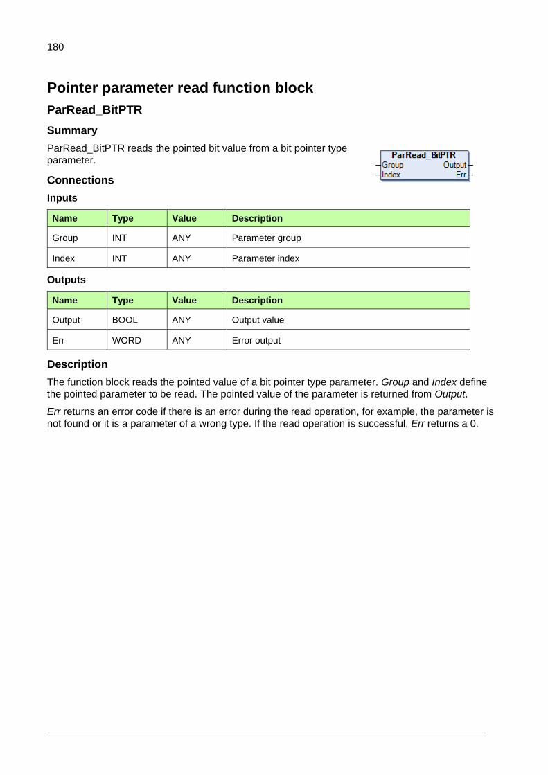
180
Pointer parameter read function block
ParRead_BitPTR
Summary
ParRead_BitPTR reads the pointed bit value from a bit pointer type
parameter.
Connections
Inputs
Name Type Value Description
Group INT ANY Parameter group
Index INT ANY Parameter index
Outputs
Name Type Value Description
Output BOOL ANY Output value
Err WORD ANY Error output
Description
The function block reads the pointed value of a bit pointer type parameter. Group and Index define
the pointed parameter to be read. The pointed value of the parameter is returned from Output.
Err returns an error code if there is an error during the read operation, for example, the parameter is
not found or it is a parameter of a wrong type. If the read operation is successful, Err returns a 0.
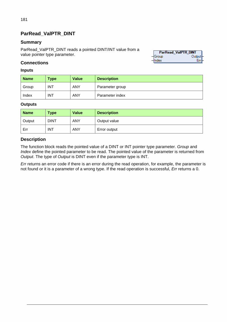
181
ParRead_ValPTR_DINT
Summary
ParRead_ValPTR_DINT reads a pointed DINT/INT value from a
value pointer type parameter.
Connections
Inputs
Name Type Value Description
Group INT ANY Parameter group
Index INT ANY Parameter index
Outputs
Name Type Value Description
Output DINT ANY Output value
Err INT ANY Error output
Description
The function block reads the pointed value of a DINT or INT pointer type parameter. Group and
Index define the pointed parameter to be read. The pointed value of the parameter is returned from
Output. The type of Output is DINT even if the parameter type is INT.
Err returns an error code if there is an error during the read operation, for example, the parameter is
not found or it is a parameter of a wrong type. If the read operation is successful, Err returns a 0.

182
ParRead_ValPTR_REAL
Summary
ParRead_ValPTR_REAL reads a pointed REAL value from a value
pointer type parameter.
Connections
Inputs
Name Type Value Description
Group INT ANY Parameter group
Index INT ANY Parameter index
Outputs
Name Type Value Description
Output REAL ANY Output value
Err INT ANY Error output
Description
The function block reads the pointed value of a REAL pointer type parameter. Group and Index
define the pointed parameter to be read. The pointed value of the parameter is returned from Output.
Err returns an error code if there is an error during the read operation, for example, the parameter is
not found or it is a parameter of a wrong type. If the read operation is successful, Err returns a 0.

183
ParRead_ValPTR_UDINT
Summary
ParRead_ValPTR_UDINT reads a pointed UDINT/UINT value from
a value pointer type parameter.
Connections
Inputs
Name Type Value Description
Group INT ANY Parameter group
Index INT ANY Parameter index
Outputs
Name Type Value Description
Output UDINT ANY Output value
Err INT ANY Error output
Description
The function block reads the pointed value of a UDINT or UINT pointer type parameter. Group and
Index define the pointed parameter to be read. The pointed value of the parameter is returned from
Output. The type of Output is UDINT even if the parameter type is UINT.
Err returns an error code if there is an error during the read operation, for example, the parameter is
not found or it is a parameter of a wrong type. If the read operation is successful, Err returns a 0.

184
GetPtrParConf
Summary
GetPtrParConf shows the source parameter settings. Source
parameter must be value pointer, bit pointer or formatted
number (parameterIndexFB).
Conections
Inputs
Name Type Value Description
S_Group INT ANY Source parameter group
S_Index INT ANY Source parameter index
Outputs
Name Type Value Description
Err INT ANY Error output.
0 = OK
3 = Invalid mapping type.
S_Type INT 0-6 Source parameter type:
0 = Unsigned 16-bit integer
1 = Signed 16-bit integer
2 = Unsigned 32-bit integer
3 = Signed 32-bit integer
4 = 32-bit Value pointer
5 = 32-bit Floating pointer
6 = 32-bit Bit pointer
T_Group INT ANY Destination parameter group.
T_Index INT ANY Destination parameter index.
BitNro INT 0-31 Bit number, when bit mapping is used.
ListIdx INT 0-N Index of list, when list is used.
Format INT 0-5 Showing, what type of mapping (external interface) is selected. If 0, no available.
u32MAPFLAG_I16 (1)
u32MAPFLAG_U16 (2)
u32MAPFLAG_FLOAT (3)
u32MAPFLAG_I32 (4)
u32MAPFLAG_U32 (5)
Description
Block is showing source parameter settings.

185
If source parameter type is formatted number/ parameterIndexFB, then parameter supports
additional selection dialog (Other) in tools (selection list), where external interface selection can be
changed. Format pin is showing the selection.
Based on this information (16bit/32bit/Float), original destination parameter(s) can be referenced by
other blocks.
This is useful for example in cases, where the same destination parameter has different scaling
factors, depending on mapped data type (16bit or 32bit).
Note that this selection is not affecting into interface, which is used by source parameter and
in case source parameter is application parameter with option formatted number/ parameterIndexFB,
it cannot be directly used by any other blocks.
When value pointer type source parameter is mapped into some destination parameter, T_Group,
T_Index are showing the destination parameter.
If the source parameter points into application variable, it cannot be mapped. All the other outputs
are 0.
If the source parameter (parameterIndexFB) is supporting external interface settings with Set pointer
parameter/other, then Format is showing selected external interface.
If the source parameter is mapped into list, then T_Group, T_Index are showing the parameter,
which corresponds the list member. BitNro is showing selected bit, and ListIdx is showing selected
list index.
If the list member represent constant value, then T_Group = 0. T_index is showing either 1 (list
member =TRUE) or 0 (list member=FALSE) value.
If the source parameter is mapped into bit (BitPtr), then BitNro is showing selected bit number.
T_Group, T_Index are indicating the destination parameter.
If source parameter is mapped into formatted number with display format parameterIndexFB,
S_Type is NUMTYPE_u32 (2) and Format is showing selected external interface.
Avoid to put this block into fast cycle and keep the amount of blocks(instances) in minimum.

186
Set pointer parameter to IEC variable function blocks
Note: The old applications which are using these blocks of the earlier system library version (1.9.0.x) must be updated to the new library version (1.9.1.0.) Otherwise the application loading fault xxx occurs (aux code : 0x800A). You can also notice that the old Par_set_ValPtr_IEC_xx are storing the value by default and new block must have store input TRUE to have equal function. However it not recommend to use Store option if the value is changed repeatedly.
ParSet_BitPTR_IEC
Summary
ParSet_BitPTR_IEC sets a bit pointer parameter to point to a bit type IEC variable.
Connections
Inputs
Name Type Value Description
Group INT ANY Parameter group
Index INT ANY Parameter index
BitNro INT 0 Bit setting is not supported.
Store BOOL T/F New value is stored to permanent memory of the drive. Default is FALSE, but no storing.
IEC_Var BOOL T/F IEC variable
Outputs
Name Type Value Description
Err INT ANY Error output
Description
The function block sets a bit pointer type parameter to point to an IEC variable of the Boolean type,
that is, the IEC variable overwrites the value of the bit pointer. The parameter to point must be of the
bit pointer type. Group and Index define the parameter. The BitNro input must be set to zero since
(at least in this library version) the type of IEC_Var must be Boolean and type of the parameter to be
set must be bit pointer. Therefore the bit number cannot be chosen. The Store pin is used to save
the pointer setting to the drive permanent memory. During next power up, the drive memorizes this
setting. The IEC_Var input is the IEC variable to be pointed.
Err returns an error code if there is an error during the set operation, for example, the parameter is
not found or it is a parameter of a wrong type. If the set operation is successful, Err returns a 0.

187
ParSet_ValPTR_IEC_DINT
Summary
ParSet_ValPTR_IEC_DINT sets a value pointer
parameter to point to a DINT type IEC variable.
Connections
Inputs
Name Type Value Description
Group INT ANY Parameter group
Index INT ANY Parameter index
Store BOOL T/F New value is stored to permanent memory of the drive. Default is FALSE, but no storing.
IEC_Var DINT ANY IEC variable
Outputs
Name Type Value Description
Err INT ANY Error output
Description
The function block sets a value pointer type parameter to point to an IEC variable of the DINT type,
that is, the IEC variable value overwrites the value of the value pointer. The parameter to point must
be a value pointer to the DINT or INT type. Group and Index define the parameter. The Store pin is
used to save the pointer setting to the drive permanent memory. During next power up, the drive
memorizes this setting. The IEC_Var input is the IEC variable to be pointed.
Err returns an error code if there is an error during the set operation, for example, the parameter is
not found or it is a parameter of a wrong type. If the set operation is successful, Err returns a 0.

188
ParSet_ValPTR_IEC_REAL
Summary
ParSet_ValPTR_IEC_REAL sets a value pointer
parameter to point to a REAL type IEC variable.
Connections
Inputs
Name Type Value Description
Group INT ANY Parameter group
Index INT ANY Parameter index
Store BOOL T/F New value is stored to permanent memory of the drive. Default is FALSE, but no storing.
IEC_Var REAL ANY IEC variable
Outputs
Name Type Value Description
Err INT ANY Error output
Description
The function block sets a value pointer type parameter to point to an IEC variable of the REAL type,
that is, the IEC variable value overwrites the value of the value pointer. The parameter to point must
be a value pointer to the REAL type. Group and Index define the parameter. The Store pin is used to
save the pointer setting to the drive permanent memory. During next power up, the drive memorizes
this setting. The IEC_Var input is the IEC variable to be pointed.
Err returns an error code if there is an error during the set operation, for example, the parameter is
not found or it is a parameter of a wrong type. If the set operation is successful, Err returns a 0.
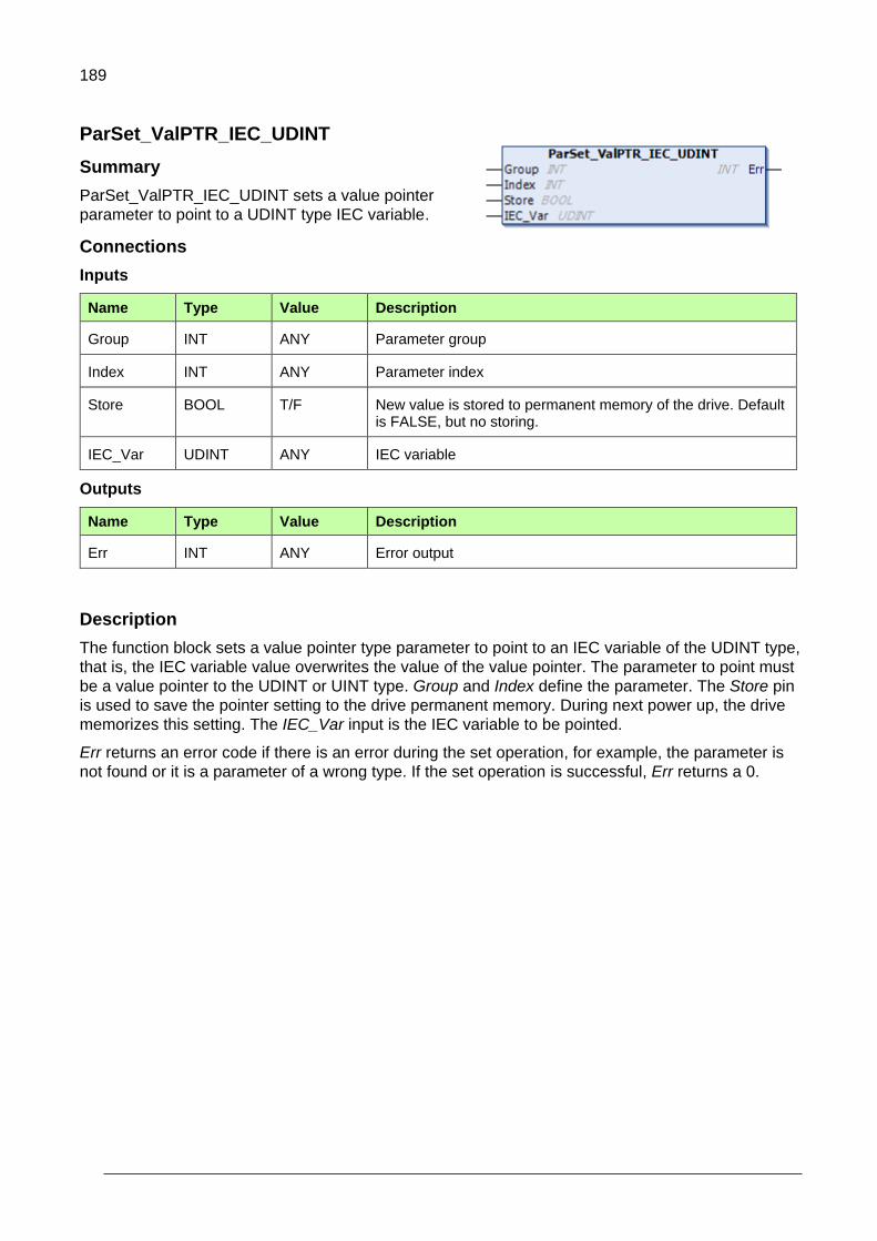
189
ParSet_ValPTR_IEC_UDINT
Summary
ParSet_ValPTR_IEC_UDINT sets a value pointer
parameter to point to a UDINT type IEC variable.
Connections
Inputs
Name Type Value Description
Group INT ANY Parameter group
Index INT ANY Parameter index
Store BOOL T/F New value is stored to permanent memory of the drive. Default is FALSE, but no storing.
IEC_Var UDINT ANY IEC variable
Outputs
Name Type Value Description
Err INT ANY Error output
Description
The function block sets a value pointer type parameter to point to an IEC variable of the UDINT type,
that is, the IEC variable value overwrites the value of the value pointer. The parameter to point must
be a value pointer to the UDINT or UINT type. Group and Index define the parameter. The Store pin
is used to save the pointer setting to the drive permanent memory. During next power up, the drive
memorizes this setting. The IEC_Var input is the IEC variable to be pointed.
Err returns an error code if there is an error during the set operation, for example, the parameter is
not found or it is a parameter of a wrong type. If the set operation is successful, Err returns a 0.
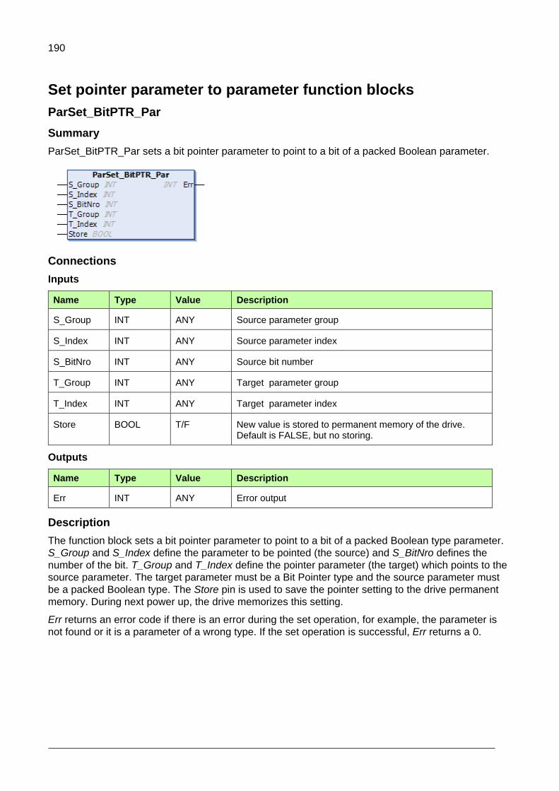
190
Set pointer parameter to parameter function blocks
ParSet_BitPTR_Par
Summary
ParSet_BitPTR_Par sets a bit pointer parameter to point to a bit of a packed Boolean parameter.
Connections
Inputs
Name Type Value Description
S_Group INT ANY Source parameter group
S_Index INT ANY Source parameter index
S_BitNro INT ANY Source bit number
T_Group INT ANY Target parameter group
T_Index INT ANY Target parameter index
Store BOOL T/F New value is stored to permanent memory of the drive. Default is FALSE, but no storing.
Outputs
Name Type Value Description
Err INT ANY Error output
Description
The function block sets a bit pointer parameter to point to a bit of a packed Boolean type parameter.
S_Group and S_Index define the parameter to be pointed (the source) and S_BitNro defines the
number of the bit. T_Group and T_Index define the pointer parameter (the target) which points to the
source parameter. The target parameter must be a Bit Pointer type and the source parameter must
be a packed Boolean type. The Store pin is used to save the pointer setting to the drive permanent
memory. During next power up, the drive memorizes this setting.
Err returns an error code if there is an error during the set operation, for example, the parameter is
not found or it is a parameter of a wrong type. If the set operation is successful, Err returns a 0.

191
ParSet_ValPTR_Par
Summary
ParSet_ValPTR_Par sets a value pointer parameter to point to
a value parameter.
Connections
Inputs
Name Type Value Description
S_Group INT ANY Source parameter group
S_Index INT ANY Source parameter index
T_Group INT ANY Target parameter group
T_Index INT ANY Target parameter index
Store BOOL T/F New value is stored to permanent memory of the drive. Default is FALSE, but no storing.
Outputs
Name Type Value Description
Err INT ANY Error output
Description
The function block sets a value pointer parameter to point to a value parameter. S_Group and
S_Index define the parameter to be pointed (the source). T_Group and T_Index define the pointer
parameter (the target) which points to the source parameter. The target parameter must be a pointer
parameter of the same type as the source parameter which must be a value parameter. The Store
pin is used to save the pointer setting to the drive permanent memory. During next power up, the
drive memorizes this setting.
Err returns an error code if there is an error during the set operation, for example, the parameter is
not found or it is a parameter of a wrong type. If the set operation is successful, Err returns a 0.
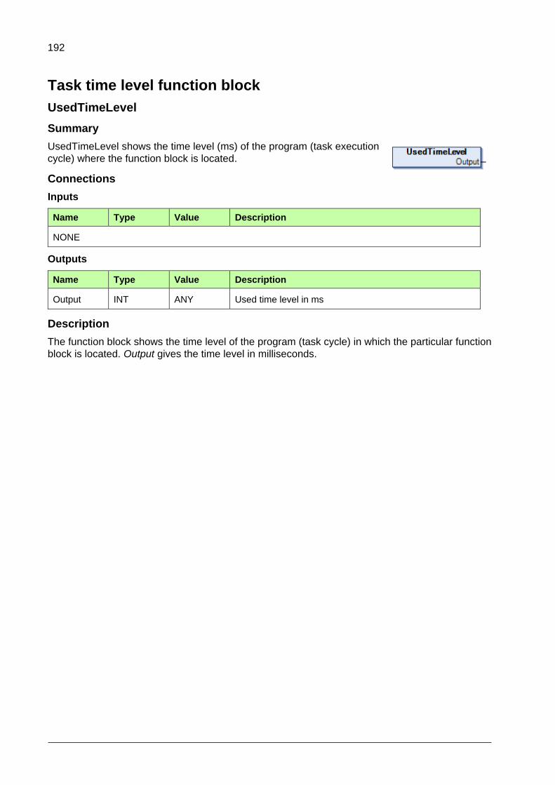
192
Task time level function block
UsedTimeLevel
Summary
UsedTimeLevel shows the time level (ms) of the program (task execution
cycle) where the function block is located.
Connections
Inputs
Name Type Value Description
NONE
Outputs
Name Type Value Description
Output INT ANY Used time level in ms
Description
The function block shows the time level of the program (task cycle) in which the particular function
block is located. Output gives the time level in milliseconds.

193
Error codes
The following list gives the most common error codes related to the function blocks of the ABB
drives system library. The error codes are received from the Err output and they indicate if there is
an error during the performance of the function block.
Error code Error code number Description
e_success 0 (hex 0) Success, no error
e_WriteProtected 4 (hex 4) The parameter is write-protected.
e_Hidden 5 (hex 5) The parameter is hidden.
e_illegalOperation 6 (hex 6) Illegal operation, for example, the parameter type is incorrect.
e_lowLimit 9 (hex 9) Parameter minimum value is exceeded.
e_highLimit 10 (hex A) Parameter maximum value is exceeded
e_noValueInList 11 (hex B) No value in the list
e_parNotFound 13 (hex D) The parameter is not found.
e_OutsideIndexArea 774 (hex 306) Outside index area
e_OverLappingGroup 775 (hex 307) Overlapping group
e_UffError 777 (hex 309) UFF error

194
Appendix D: ABB D2D function blocks
Contents of this chapter
This appendix contains detailed information of the drive to drive (D2D) communication function
blocks of the ABB drives D2DComm library AY2LB_D2DComm_ACS880_V3_5.
Introduction to ABB D2D function blocks
The ABB D2D function blocks are intended to be used with the ACS880 drives. It provides drive to
drive communication and drive to drive configuration function blocks for application programming in
the automation builder environment. The description of the features in this document is based on the
ABB drives D2D communication library version 1.9.0.2.
Note: In the Drive Composer Pro system information, make sure the drive has the
corresponding system library installed. In System info, the D2DComm library version is
located under the Products/ More view. The D2DComm library versions must be the
same in the drive and the application program project.
14
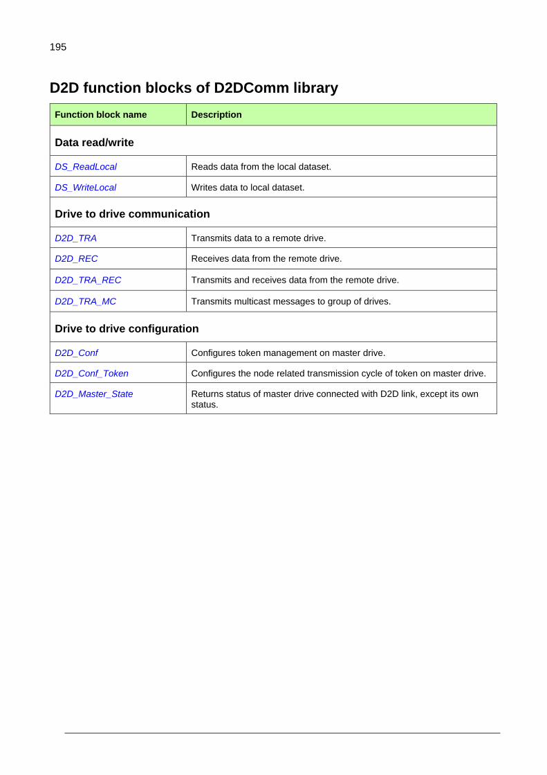
195
D2D function blocks of D2DComm library
Function block name Description
Data read/write
DS_ReadLocal Reads data from the local dataset.
DS_WriteLocal Writes data to local dataset.
Drive to drive communication
D2D_TRA Transmits data to a remote drive.
D2D_REC Receives data from the remote drive.
D2D_TRA_REC Transmits and receives data from the remote drive.
D2D_TRA_MC Transmits multicast messages to group of drives.
Drive to drive configuration
D2D_Conf Configures token management on master drive.
D2D_Conf_Token Configures the node related transmission cycle of token on master drive.
D2D_Master_State Returns status of master drive connected with D2D link, except its own status.

196
Data read/write blocks
DS_ReadLocal
Summary
DS_ReadLocal block reads the dataset value from the
local dataset table. The 48 bit dataset composes of 16 bit
and 32 bit parts. The 32 bit part is available both in
DWORD or REAL data formats in the function block output. Inputs are pointer to actual data.
Dataset composes of three words in the output:
16 bit (WORD)
32 bit (DWORD or REAL)
Connections
Inputs
Name Type Value Description
LocalDsNr UINT 1…255 Local dataset number
Outputs
Name Type Value Description
Error UDINT ANY Error output
Out1_16bit WORD ANY 16-bit part of the dataset in WORD format
Out2_32bit DWORD ANY 32-bit part of the dataset as DWORD format
Out2_32bitReal REAL ANY 32-bit part of the dataset as REAL format
Description
The function block reads the local dataset value from the local dataset table. LocalDsNr defines the
local dataset number.
Output Out1_16bit returns the first 16 bit of dataset as WORD data.
Output Out2_32bit returns 32 bit part of dataset as DWORD data.
Output Out2_32bitReal returns 32 bit part of dataset as REAL data.
Error returns an error code if there is an error during the read operation, for example, the dataset is
not found or if the dataset is beyond the dataset number range of 1…255. If the read operation is
successful, Error returns a 0.
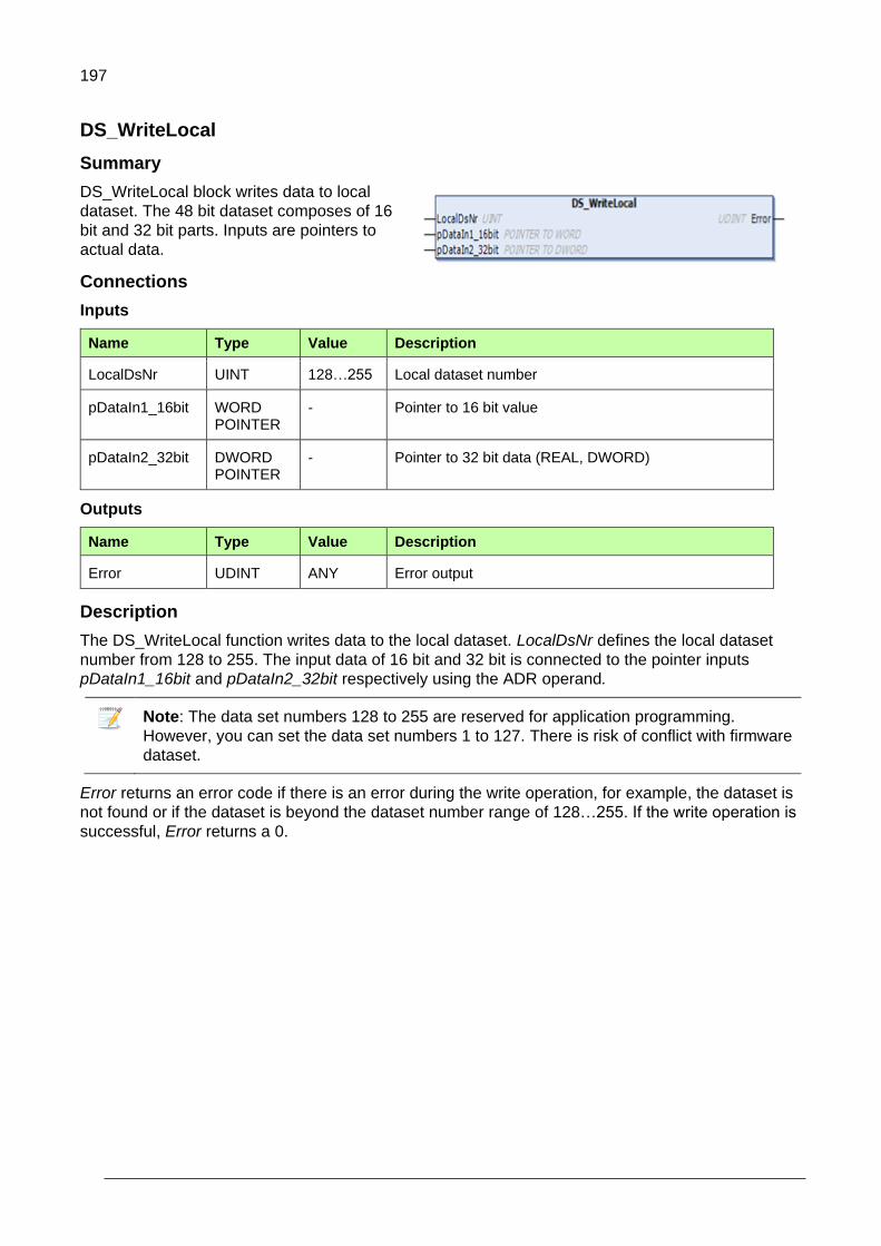
197
DS_WriteLocal
Summary
DS_WriteLocal block writes data to local
dataset. The 48 bit dataset composes of 16
bit and 32 bit parts. Inputs are pointers to
actual data.
Connections
Inputs
Name Type Value Description
LocalDsNr UINT 128…255 Local dataset number
pDataIn1_16bit WORD POINTER
- Pointer to 16 bit value
pDataIn2_32bit DWORD POINTER
- Pointer to 32 bit data (REAL, DWORD)
Outputs
Name Type Value Description
Error UDINT ANY Error output
Description
The DS_WriteLocal function writes data to the local dataset. LocalDsNr defines the local dataset
number from 128 to 255. The input data of 16 bit and 32 bit is connected to the pointer inputs
pDataIn1_16bit and pDataIn2_32bit respectively using the ADR operand.
Note: The data set numbers 128 to 255 are reserved for application programming.
However, you can set the data set numbers 1 to 127. There is risk of conflict with firmware
dataset.
Error returns an error code if there is an error during the write operation, for example, the dataset is
not found or if the dataset is beyond the dataset number range of 128…255. If the write operation is
successful, Error returns a 0.

198
D2D communication blocks
General
The D2D_TRA, D2D_REC and D2D_TRA_REC blocks can be used only in a master drive. These
blocks can work independently without token configuration. The D2D_TRA_MC block can be used in
both master and follower drives. When used in a follower drive, the token send configuration must be
done using D2D_Conf_Token and D2D_Conf blocks.
The D2D_Master_State block can be used without token configuration in both the master and
follower drives as well as the local dataset blocks DS_ReadLocal and DS_WriteLocal.
D2D_TRA
Summary
D2D_TRA block sends data from a Master
drive to a remote Follower drive. The 48 bit
data composes of 16 bit and 32 bit parts.
The input data is given directly to the
function block inputs and so local datasets
are not required.
Connections
Inputs
Name Type Value Description
Enable BOOL T/F Enables/disables sending data.
Pri UINT 1/2 Defines the priority of sending data; Standard (1) or Low priority (2).
RemoteNode UINT 1…62 Defines the remote drive node address.
RemoteDsNr UINT 128….255 Defines the remote drive dataset number.
pDataIn1_16bit WORD POINTER
- Pointer to 16 bit value
pDataIn2_32bit DWORD POINTER
- Pointer to 32 bit data (REAL, DWORD)
Outputs
Name Type Value Description
Error UDINT ANY Error output
SendMsgCnt UDINT ANY Counts successfully transmitted messages

199
Description
The D2D_TRA function sends application variables data from the master drive to a remote follower
drive. The Enable input enables or disables sending data. At the rising edge of Enable input Pri,
RemoteNode and RemoteDsNr are used. The input Pri defines the priority of data transmission.
Standard (1): The priority is set to Standard if fast response (2 ms) is required. However,
maximum of 2 blocks can be executed in the same cycle.
Low priority (2): The priority is set to Low priority if slow response is required. It is possible to
execute up to 64 blocks in the same cycle.
o 10 ms cycle time - 10 blocks are executed
o 100 ms cycle time - 64 blocks are executed
The inputs RemoteNode and RemoteDsNr define the remote drive node address and dataset
number respectively, where the data is sent and stored. The input data of 16 bit and 32 bit is
connected to the pointer inputs pDataIn1_16bit and pDataIn2_32bit respectively using ADR
operand.
Error blocks input values and operation status if there is an error while sending data. If data is sent
successfully, Error returns a 0. The SendMsgCount tracks the number of successfully sent
messages.
For details of how data is sent in WORD and REAL data format to remote drive, see Example 1:
D2D_TRA / D2D_REC blocks.

200
D2D_REC
Summary
D2D_REC block enables the master drive to
receive data from a remote follower drive. The
block receives one 48 bit dataset from follower
dataset table. The response is available at the
output signals in 16 bit and 32 bit parts. An
additional 32 bit data is available in REAL format as own output.
Connections
Inputs
Name Type Value Description
Enable BOOL T/F Enables/disables receiving data.
Pri UINT 1/2 Defines the priority of receiving data; Standard (1) or Low priority (2).
RemoteNode UINT 1…62 Defines the remote drive node address.
RemoteDsNr UINT 128…255 Defines the remote drive dataset number.
SuspendMode UINT 0/1 Defines the behaviour of the application task whether the D2D message is sent.
0 = message not sent
1 = message sent
Outputs
Name Type Value Description
Error UDINT ANY Error output
RcvMsgCnt UDINT ANY Counts successfully received messages
Out1_16bit WORD ANY 16-bit dataset output value
Out2_32bit DWORD ANY 32-bit dataset output value
Out2_32bitReal REAL ANY 32-bit dataset output value in Real format.
Description
The D2D_REC block receives data from remote drive. The Enable input enables or disables
receiving data. At the rising edge of Enable input the inputs Pri, RemoteNode, RemoteDsNr and
SuspendMode are used. The input Pri defines the priority of receiving data.
Standard (1): The priority is set to Standard if fast response (2 ms) is required. However,
maximum of 2 blocks can be executed in the same cycle.
Low priority (2): The priority is set to Low priority if slow response is required. It is possible to
execute up to 64 blocks in the same cycle.
o 10 ms cycle time - 10 blocks are executed
o 100 ms cycle time - 64 blocks are executed

201
The inputs RemoteNode and RemoteDsNr define the remote drive node address and dataset
number respectively. The remote node number is set using parameter 60.02 in the ACS880 Primary
Control Program. The input SuspendMode defines the behavior of the application task whether the
intended message is sent.
0 = continues actual application task execution
1 = indicates that actual application task execution is pending to send messages and to receive
response of messages sent.
Error blocks input values and operation status if there is an error while receiving data. If receiving
data is successful, Error returns a 0. The RcvMsgCount tracks the number of successfully received
messages.
The 16 bit and 32 bit data at the output returns from Out1_16bit and Out2_32bit respectively. The 32
bit data of real data format returns from Out2_32bitReal.
For details of receiving data to master drive, see Example 1: D2D_TRA / D2D_REC blocks.
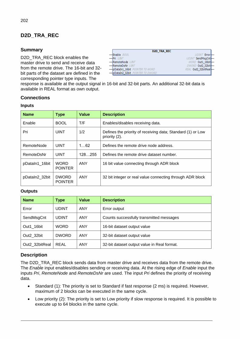
202
D2D_TRA_REC
Summary
D2D_TRA_REC block enables the
master drive to send and receive data
from the remote drive. The 16-bit and 32-
bit parts of the dataset are defined in the
corresponding pointer type inputs. The
response is available at the output signal in 16-bit and 32-bit parts. An additional 32-bit data is
available in REAL format as own output.
Connections
Inputs
Name Type Value Description
Enable BOOL T/F Enables/disables receiving data.
Pri UINT 1/2 Defines the priority of receiving data; Standard (1) or Low priority (2).
RemoteNode UINT 1…62 Defines the remote drive node address.
RemoteDsNr UINT 128…255 Defines the remote drive dataset number.
pDataIn1_16bit WORD POINTER
ANY 16 bit value connecting through ADR block
pDataIn2_32bit DWORD POINTER
ANY 32 bit integer or real value connecting through ADR block
Outputs
Name Type Value Description
Error UDINT ANY Error output
SendMsgCnt UDINT ANY Counts successfully transmitted messages
Out1_16bit WORD ANY 16-bit dataset output value
Out2_32bit DWORD ANY 32-bit dataset output value
Out2_32bitReal REAL ANY 32-bit dataset output value in Real format.
Description
The D2D_TRA_REC block sends data from master drive and receives data from the remote drive.
The Enable input enables/disables sending or receiving data. At the rising edge of Enable input the
inputs Pri, RemoteNode and RemoteDsNr are used. The input Pri defines the priority of receiving
data.
Standard (1): The priority is set to Standard if fast response (2 ms) is required. However,
maximum of 2 blocks can be executed in the same cycle.
Low priority (2): The priority is set to Low priority if slow response is required. It is possible to
execute up to 64 blocks in the same cycle.

203
o 10 ms cycle time - 10 blocks are executed
o 100 ms cycle time - 64 blocks are executed
The inputs RemoteNode and RemoteDsNr define the remote drive node address and dataset
number respectively. The response data is read from the dataset number RemoteDsNr+1 of the
remote drive. The data is selected using pointer inputs pDataIn1_16bit and pDataIn2_32bit.
Error blocks input values and operation status if there is an error while sending or receiving data. If
sending or receiving data is successful, Error returns a 0. The SendMsgCount tracks the number of
successfully sent messages.
The 16-bit and 32-bit data at the output returns from Out1_16bit and Out2_32bit respectively. The
additional output Out2_32bitReal returns 32-bit data in REAL data format.

204
D2D_TRA_MC
Summary
D2D_TRA_MC block enables the drive (Master
or Follower) to send multicast messages to a
group of drives. This block also allows sending
follower to follower point to point messages.
The multicast address is defined in the
D2D_Conf block.
Connections
Inputs
Name Type Value Description
Enable BOOL T/F Enables/disables receiving data.
Pri UINT 1/2 Defines the priority of receiving data; Standard (1) or Low priority (2).
MultiCastType UINT 0/1 Allows sending multicast message types.
RemoteNode UINT 1…62 Defines the remote drive node address.
RemoteDsNr UINT 128…255 Defines the remote drive dataset number.
pDataIn1_16bit WORD POINTER
ANY 16 bit value connecting through ADR block
pDataIn2_32bit DWORD POINTER
ANY 32 bit integer or real value connecting through ADR block
Outputs
Name Type Value Description
Error UDINT ANY Error output
SendMsgCnt UDINT ANY Counts successfully transmitted messages
Description
The D2D_TRA_MC block sends multicast messages to a group of drives. It is possible for the
Master drive to receive messages from the Follower driver. For sending point to point messages or
standard multicast messages, the Follower drives need token messages from the Master drive.
The Enable input enables/disables sending data. At the rising edge of Enable input the inputs Pri,
MultiCastType, RemoteNode and RemoteDsNr are used.

205
The input Pri defines the priority of receiving data.
Standard (1): The priority is set to Standard if fast response (2 ms) is required. However,
maximum of 2 blocks can be executed in the same cycle.
Low priority (2): The priority is set to Low priority if slower response is sufficient. Up to 64 blocks can be executed in the same cycle.
o 10 ms cycle time - 10 blocks are executed
o 100 ms cycle time - 64 blocks are executed
The input MultiCastType enables sending multicast messages of 3 different types:
Follower point to point transmit (3)
Standard Multicast (4): This message type requires all Follower/Master drives to have a
corresponding multicast address equal to the RemoteNode.
Broadcast (5): In this message type all drives in the drive to drive link receive the message
including the Master drive. In this mode, the input RemoteNode must be set to 255.
The inputs RemoteNode and RemoteDsNr define the remote drive node address and dataset
number respectively. The data is selected using pointer inputs pDataIn1_16bit and pDataIn2_32bit.
Error blocks input values and operation status if there is an error while sending or receiving data. If
sending or receiving data is successful, Error returns a 0. The SendMsgCount tracks the number of
successfully sent messages.

206
D2D configuration blocks
D2D_Conf
Summary
D2D_Conf block configures token management on the
master drive. The D2D_Conf_Token block must be
executed before the D2D_Conf block because
configuration data is built based on the node data in
D2D_Conf_Token block.
Connections
Inputs
Name Type Value Description
Enable BOOL T/F Enables/disables configuration data in Master drive.
Value FALSE stops sending token from master to follower(s).
MCastGrp UINT - Defines multicast group address.
TokenTxmCycle UINT 1000…10000 Sends the interval of token message.
0 = indicates that current configuration is removed
Outputs
Name Type Value Description
Error UDINT Any Error output
Description
The D2D_Conf block is intended to execute only once, and for this reason, the block should be
assigned to Pre_Task. However, the block can be assigned to any task and in cyclic tasks, the
Enable input controls the execution, including run time configuration.
The configured data is effective on the master drive after enabling the D2D_Conf block. The Enable
input enables/disables the configuration data on the master drive. The rising edge of Enable input
triggers the configuration setup. The next rising edge overwrites the Enable input of
D2D_Conf_Token block, even if it is set to FALSE.
The input TokenTxmCycle is the base transmission cycle of token. The node related transmission
cycle is attained by multiplying this value set in the D2D_Conf_Token block.
Error blocks input values and operation status if there is an error in the configuration data. If
configuration is successful, Error returns a 0.
Master use
The master drive has a message queue to handle cyclic transmission of the token messages to
follower drive. This queue can hold maximum 64 token messages. The standard multicast group of
master drive (address) is defined by the input MCastGrp.

207
Follower use
In the follower drive, only the multicast group (MCastGrp) can be defined and TokenTxmCycle is not
used. The master drive transmits the token messages to follower drives. After receiving a token the
follower is able to transmit a message from the D2D message queue.
For example of token configuration, see Example 2: Token send configuration using
D2D_Conf_Token and D2D_Conf blocks.
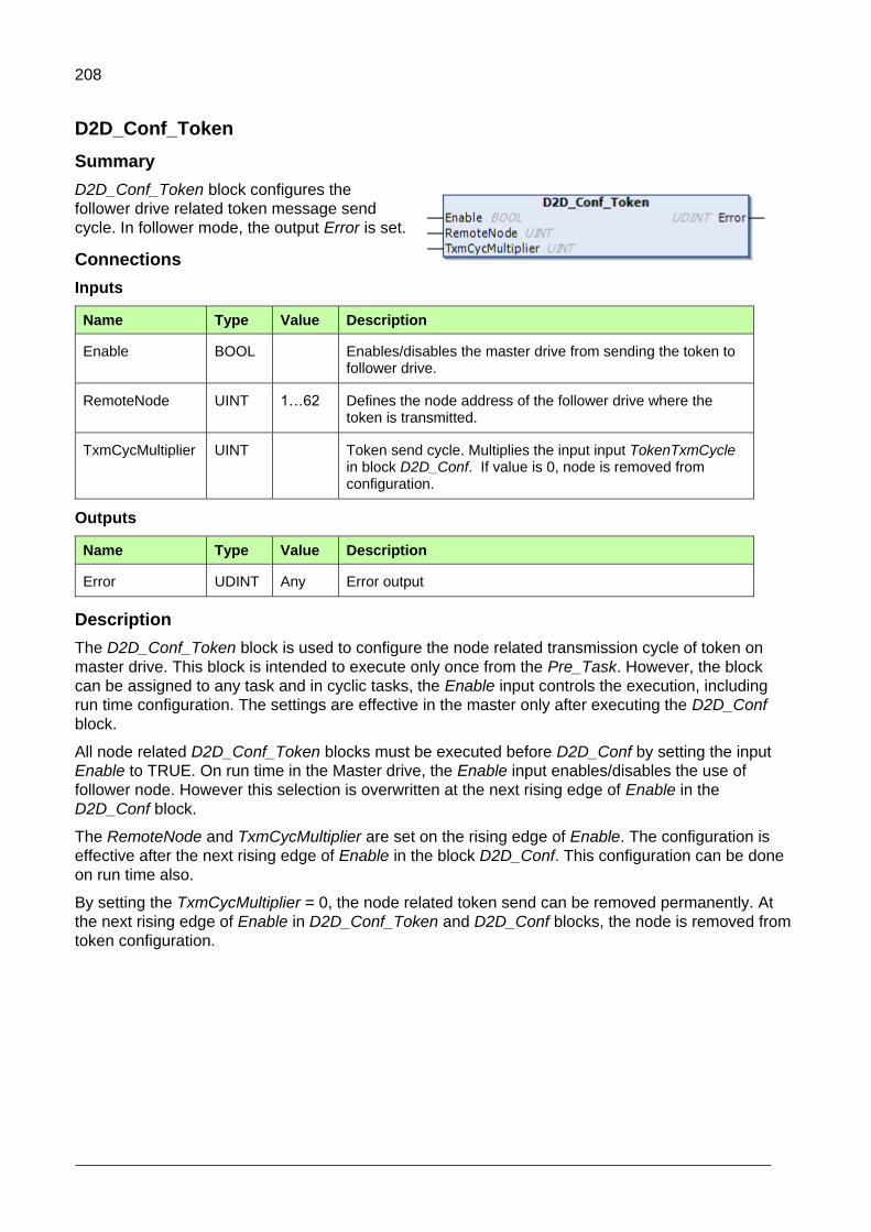
208
D2D_Conf_Token
Summary
D2D_Conf_Token block configures the
follower drive related token message send
cycle. In follower mode, the output Error is set.
Connections
Inputs
Name Type Value Description
Enable BOOL Enables/disables the master drive from sending the token to follower drive.
RemoteNode UINT 1…62 Defines the node address of the follower drive where the token is transmitted.
TxmCycMultiplier UINT Token send cycle. Multiplies the input input TokenTxmCycle in block D2D_Conf. If value is 0, node is removed from configuration.
Outputs
Name Type Value Description
Error UDINT Any Error output
Description
The D2D_Conf_Token block is used to configure the node related transmission cycle of token on
master drive. This block is intended to execute only once from the Pre_Task. However, the block
can be assigned to any task and in cyclic tasks, the Enable input controls the execution, including
run time configuration. The settings are effective in the master only after executing the D2D_Conf
block.
All node related D2D_Conf_Token blocks must be executed before D2D_Conf by setting the input
Enable to TRUE. On run time in the Master drive, the Enable input enables/disables the use of
follower node. However this selection is overwritten at the next rising edge of Enable in the
D2D_Conf block.
The RemoteNode and TxmCycMultiplier are set on the rising edge of Enable. The configuration is
effective after the next rising edge of Enable in the block D2D_Conf. This configuration can be done
on run time also.
By setting the TxmCycMultiplier = 0, the node related token send can be removed permanently. At
the next rising edge of Enable in D2D_Conf_Token and D2D_Conf blocks, the node is removed from
token configuration.

209
Error blocks input values and operation status. The error messages are listed below:
Bit Error code Meaning
0 D2D_MODE_ERR D2D mode is not Master
5 TOO_SHORT_CYCLE Token interval(s) are short or communication is overloaded
6 INVALID_INPUT_VAL Input value (target node and/or cycle time) are out of range
7 GENERAL_D2D_ERR D2D driver failed to initialize message
For example of token configuration, see Example 2: Token send configuration using
D2D_Conf_Token and D2D_Conf blocks.

210
D2D_Master_State
Summary
D2D_Master_State block reads bit related Master state
of all the drives connected into the D2D link. From the
master drive, this block broadcasts the master state to
other drives using node number. This block works without token management configuration.
Connections
Inputs
Name Type Value Description
Enable BOOL T/F Enables/disables block execution
Reset BOOL 0/1 Resets all master state bits on rising edge
Node UINT 1…62 Node address
Outputs
Name Type Value Description
Error UDINT ANY Error output
MstState1 UDINT 0…31 Drive/node related master bits 0…31. Bit 0 == Node1
MstState2 UDINT 32…63 Drive/node related master bits 32…63.
Description
The D2D_Master_State block is used when there is a risk to have multiple masters in same D2D
link. This enables creating systems with redundant masters. The block returns status of all Master
drives connected into the D2D link, except its own state, which can be set and read using parameter
60.3 (M/F mode). As the Master drive broadcasts its state to other drives based on Node address,
the panel port communication port parameter 49.1 (Node ID number) should also be using the same
value.
The master drive state bits are updated when the input Reset is set FALSE. The reset function can
be used whenever there is state change from Master to Slave.
The input Node is same as parameter 60.2 (M/F node address).
Error blocks input values and operation status. In the follower drive, the output Error returns the
D2D_MODE_ERR code to notify that the drive is not able to broadcast master state; however the
block is able to read other drive states.
The output MstState1 includes drive/node related master bits 0 to 31. If this output is set, the drive is
Master.
The output MstState2 includes drive/note related master bits 32 to 63.
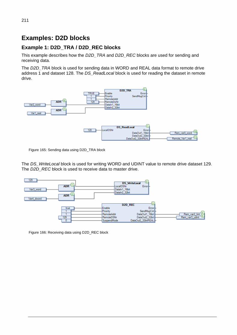
211
Examples: D2D blocks
Example 1: D2D_TRA / D2D_REC blocks
This example describes how the D2D_TRA and D2D_REC blocks are used for sending and
receiving data.
The D2D_TRA block is used for sending data in WORD and REAL data format to remote drive
address 1 and dataset 128. The DS_ReadLocal block is used for reading the dataset in remote
drive.
Figure 165: Sending data using D2D_TRA block
The DS_WriteLocal block is used for writing WORD and UDINT value to remote drive dataset 129.
The D2D_REC block is used to receive data to master drive.
Figure 166: Receiving data using D2D_REC block

212
Example 2: Token send configuration blocks
This example describes how the D2D_Conf_Token and D2D_Conf blocks are used for sending
tokens.
In token send configuration, the master drive configures the token. After the follower receives a
token from the mater, the follower node sends follower to follower (point to point) or multicast
message.
Using the D2D_Conf_Token block you can add a node into the token send configuration with own
instance or common instance. The below examples is a common instance configuration using the
ConfToken. When all the nodes are included the D2D_Conf is executed.
In this example, a previous configuration with the following nodes existed: remoteNode1 and
remoteNode2. A new configuration is set that includes only remoteNode1 for which remoteNode2
must be removed from the existing configuration.
Each testStep represents a separately executed run cycle.
testStep(1) - remoteNode1 is added into new configuration
testStep(3) - remoteNode2 is removed from configuration
testStep(4) - D2D_Conf is invoked and starts sending token to remoteNode1
Master
Drive
remoteNode1 remoteNode2
D2D_Conf
D2D_Conf_Token
Token send
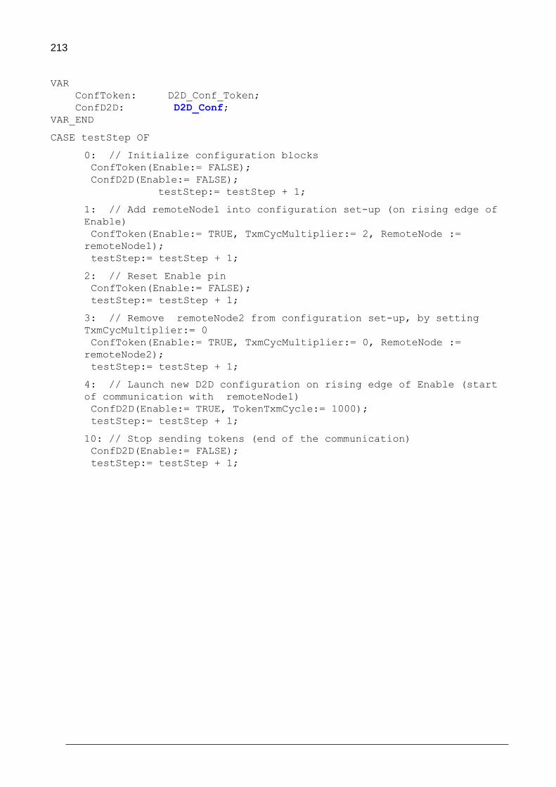
213
VAR
ConfToken: D2D_Conf_Token;
ConfD2D: D2D_Conf;
VAR_END
CASE testStep OF
0: // Initialize configuration blocks
ConfToken(Enable:= FALSE);
ConfD2D(Enable:= FALSE);
testStep:= testStep + 1;
1: // Add remoteNode1 into configuration set-up (on rising edge of
Enable)
ConfToken(Enable:= TRUE, TxmCycMultiplier:= 2, RemoteNode :=
remoteNode1);
testStep:= testStep + 1;
2: // Reset Enable pin
ConfToken(Enable:= FALSE);
testStep:= testStep + 1;
3: // Remove remoteNode2 from configuration set-up, by setting
TxmCycMultiplier:= 0
ConfToken(Enable:= TRUE, TxmCycMultiplier:= 0, RemoteNode :=
remoteNode2);
testStep:= testStep + 1;
4: // Launch new D2D configuration on rising edge of Enable (start
of communication with remoteNode1)
ConfD2D(Enable:= TRUE, TokenTxmCycle:= 1000);
testStep:= testStep + 1;
10: // Stop sending tokens (end of the communication)
ConfD2D(Enable:= FALSE);
testStep:= testStep + 1;

214
Appendix E: ABB drives standard library
Contents of this chapter
This appendix contains detailed information of the basic and special functions of the ABB drives
standard library (AS1LB_Standard_ACS880_V3_5)
Introduction to ABB drives standard library
The ABB drives standard library is intended to be used with the ACS880 drives and the AC500 PLC.
It provides frequently used control elements for application programming in automation builder.
Unlike the standard libraries provided by 3S-Smart Software Solutions, most of the function blocks in
the library use floating point numbers. This provides a more flexible development environment as the
programmer does not need to worry about handling wide numerical ranges and scaling.
The drive version of the library is generated from the PLC version to ensure that the code is not
altered in any way. For compatibility, some functions are implemented as function blocks because
the PLC does not support multiple outputs for functions. The functions do not have a state and thus
require less memory. This is also why the drive version of the library has these blocks as functions
(that is, there are 2 versions available in the drive version).
15

215
Input values are checked to be within the defined limits. If for some reason the block detects that a
value is out of range, it can:
1. Limit the value to the maximum or minimum value. For example, if the time constant is set to a
very large value or a negative value, it is limited inside the block to ensure the correct execution.
2. Produce an error signal. For example, if the low limit for the output is greater than the high limit,
the block cannot operate and produces an error.
The function blocks with a state have a balance reference and balance mode. This feature provides
the means to force the control system to a new state. By enabling the balance mode, the blocks
operate as if the balance reference is the calculated output of the block. Internal variables are also
adjusted so that once the balance mode is disabled the process continues from the balance
reference value.

216
Basic functions
BGET
Summary
The BGET function reads one selected bit from a WORD or a
DWORD (includes size check).
Connections
Inputs
Name Type Value Description
BIT_NR UINT 0…31 Bit number
IN DWORD, WORD
ANY Data input
Outputs
Name Type Value Description
BGET BOOL TRUE, FALSE
Bit value
Function
The output (BGET) is the selected bit (BIT_NR) of the input word (IN).
If BIT_NR is 0, the bit is 0. If BIT_NR is 31, the bit is 31.
If the bit number is not within the range of 0…31 (for DWORD) or 0…15 (for WORD), the output is 0.

217
BSET
Summary
The BSET function changes the state of one selected bit of a
WORD or a DWORD (includes size check).
Connections
Inputs
Name Type Value Description
EN BOOL TRUE, FALSE
Enable block
BIT_NR UINT 0…31 Bit number
BIT_VALUE BOOL TRUE, FALSE
New value for bit
IN DWORD, WORD
ANY Data input
Outputs
Name Type Value Description
BSET DWORD, WORD
ANY Changed word
Function
The value of a selected bit (BIT_NR) of the input (IN) is set as defined by the bit value input
(BIT_VALUE).
If BIT_NR is 0, the bit is 0. If BIT_NR is 31, the bit is 31. The function must be enabled by the
enable input (EN).
If the function is disabled or the bit number is not within the range of 0…31 (for DWORD) or 0…15
(for WORD), the input value is stored to the output as it is (that is, no bit setting occurs).
Example:
EN = 1, BIT_NR = 3, BIT_VALUE = 0
IN = 0000 0000 1111 1111
BSET = 0000 0000 1111 0111
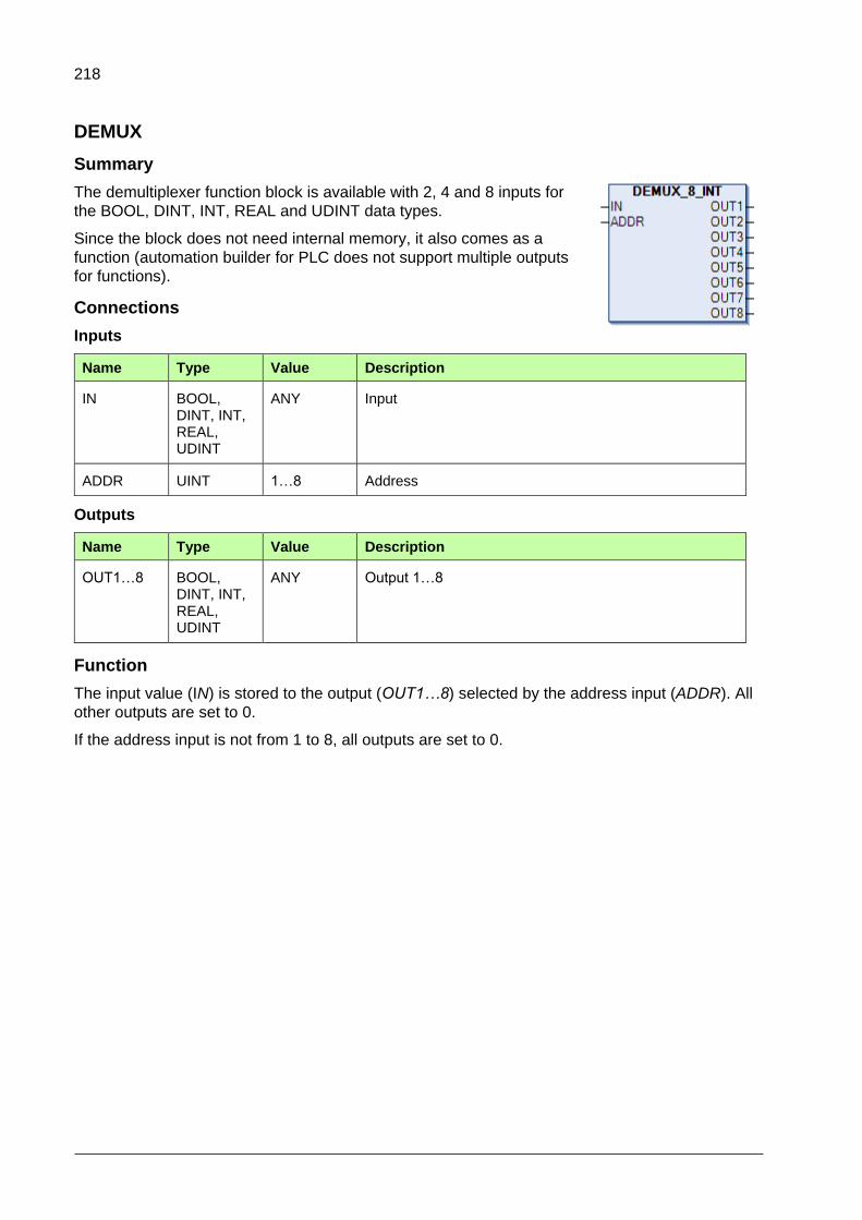
218
DEMUX
Summary
The demultiplexer function block is available with 2, 4 and 8 inputs for
the BOOL, DINT, INT, REAL and UDINT data types.
Since the block does not need internal memory, it also comes as a
function (automation builder for PLC does not support multiple outputs
for functions).
Connections
Inputs
Name Type Value Description
IN BOOL, DINT, INT, REAL, UDINT
ANY Input
ADDR UINT 1…8 Address
Outputs
Name Type Value Description
OUT1…8 BOOL, DINT, INT, REAL, UDINT
ANY Output 1…8
Function
The input value (IN) is stored to the output (OUT1…8) selected by the address input (ADDR). All
other outputs are set to 0.
If the address input is not from 1 to 8, all outputs are set to 0.

219
DEMUXM
Summary
The demultiplexer function block with an internal memory to store
output values is available with 2, 4 and 8 inputs for the BOOL, DINT,
INT, REAL and UDINT data types.
Connections
Inputs
Name Type Value Description
SET BOOL TRUE, FALSE
Set
LOAD BOOL TRUE, FALSE
Load (Set only once)
RESET BOOL TRUE, FALSE
Reset
ADDR UINT 1…8 Address
IN BOOL, DINT, INT, REAL, UDINT
ANY Input
Outputs
Name Type Value Description
OUT1…8 BOOL, DINT, INT, REAL, UDINT
ANY Output 1…8
Function
DEMUXM is used as a demultiplexer with memory. It remembers the assigned values to outputs and
continues sending them until changed or reset.
The input value (IN) is stored to the output (OUT1…8) selected by the address input (ADDR) if the
load input (LOAD) or the set input (SET) is 1.
When the load input is set to 1, the input value is stored to the output only once. When the set input
is set to 1, the input value is stored to the output every time the block is executed. The new set input
overrides the load input.
If the address input is not from 1 to 8, the outputs are not affected by the input value.
If RESET = 1, all outputs are set to 0 and the block’s memory is reset.

220
MUX
Summary
The multiplexer function for the REAL data type as the
automation builder version does not support this type. The
function block is available with 2, 4 and 8 inputs.
Connections
Inputs
Name Type Value Description
ADDR UINT 1…8 Address
IN1…8 REAL ANY Inputs 1…8
Outputs
Name Type Value Description
MUX REAL ANY Selected input value
Function
The value of an input (IN1…8) is selected by the address input (ADDR) and stored to the output
(MUX).
If the address input is not from 1 to 8, the output is set to 0.
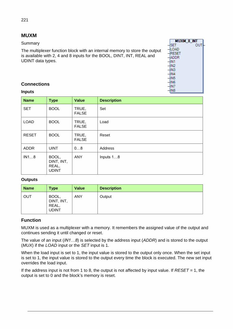
221
MUXM
Summary
The multiplexer function block with an internal memory to store the output
is available with 2, 4 and 8 inputs for the BOOL, DINT, INT, REAL and
UDINT data types.
Connections
Inputs
Name Type Value Description
SET BOOL TRUE, FALSE
Set
LOAD BOOL TRUE, FALSE
Load
RESET BOOL TRUE, FALSE
Reset
ADDR UINT 0…8 Address
IN1…8 BOOL, DINT, INT, REAL, UDINT
ANY Inputs 1…8
Outputs
Name Type Value Description
OUT BOOL, DINT, INT, REAL, UDINT
ANY Output
Function
MUXM is used as a multiplexer with a memory. It remembers the assigned value of the output and
continues sending it until changed or reset.
The value of an input (IN1…8) is selected by the address input (ADDR) and is stored to the output
(MUX) if the LOAD input or the SET input is 1.
When the load input is set to 1, the input value is stored to the output only once. When the set input
is set to 1, the input value is stored to the output every time the block is executed. The new set input
overrides the load input.
If the address input is not from 1 to 8, the output is not affected by input value. If RESET = 1, the
output is set to 0 and the block’s memory is reset.

222
PACK
Summary
The PACK function sets the BOOL inputs into a WORD or a
DWORD.
Connections
Inputs
Name Type Value Description
IN0…31 BOOL TRUE, FALSE
Bits
Outputs
Name Type Value Description
PACK WORD, DWORD
ANY Resulting pack of bits
Function
The PACK function takes an input set of bits and packs it in to a word.
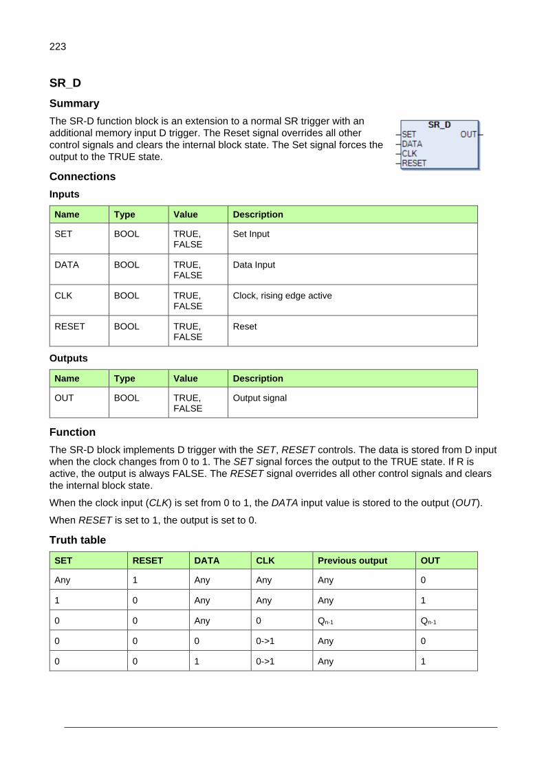
223
SR_D
Summary
The SR-D function block is an extension to a normal SR trigger with an
additional memory input D trigger. The Reset signal overrides all other
control signals and clears the internal block state. The Set signal forces the
output to the TRUE state.
Connections
Inputs
Name Type Value Description
SET BOOL TRUE, FALSE
Set Input
DATA BOOL TRUE, FALSE
Data Input
CLK BOOL TRUE, FALSE
Clock, rising edge active
RESET BOOL TRUE, FALSE
Reset
Outputs
Name Type Value Description
OUT BOOL TRUE, FALSE
Output signal
Function
The SR-D block implements D trigger with the SET, RESET controls. The data is stored from D input
when the clock changes from 0 to 1. The SET signal forces the output to the TRUE state. If R is
active, the output is always FALSE. The RESET signal overrides all other control signals and clears
the internal block state.
When the clock input (CLK) is set from 0 to 1, the DATA input value is stored to the output (OUT).
When RESET is set to 1, the output is set to 0.
Truth table
SET RESET DATA CLK Previous output OUT
Any 1 Any Any Any 0
1 0 Any Any Any 1
0 0 Any 0 Qn-1 Qn-1
0 0 0 0->1 Any 0
0 0 1 0->1 Any 1

224
SWITCH
Summary
The SWITCH function block sets the outputs the same as the input if EN equals TRUE, otherwise all
outputs are 0. SWITCH is available with 2, 4 and 8 inputs and outputs
for the BOOL, DINT, INT, REAL and UDINT data types.
Since the block does not need internal memory, it also comes as a
function (automation builder for PLC does not support multiple outputs
for functions).
Connections
Inputs
Name Type Value Description
EN BOOL TRUE, FALSE
Enable
IN1…8 BOOL, DINT, INT, REAL, UDINT
ANY Input 1…8
Outputs
Name Type Value Description
OUT1…8 BOOL, DINT, INT, REAL, UDINT
ANY Output 1…8
Function
The output (OUT1…8) is equal to the corresponding input (IN1…8) if the block is enabled (EN = 1).
Otherwise the output is 0.

225
SWITCHC
Summary
The SWITCHC function block has two channels. A channel can be chosen
by using the Select signal. If Select equals FALSE, channel A is active. If
Select equals TRUE, channel B is active. If the EN signal is not active, all
outputs are 0. SWITCHC is available with 2, 4 and 8 input pairs and
outputs for the BOOL, DINT, INT, REAL and UDINT data types.
Since the block does not need an internal memory, it also comes as a
function (automation builder for PLC does not support multiple outputs for
functions).
Connections
Inputs
Name Type Value Description
EN BOOL TRUE, FALSE
Enable
SELECT BOOL TRUE, FALSE
Select
IN1…8A BOOL, DINT, INT, REAL, UDINT
ANY Input A 1…8
IN1…8B BOOL, DINT, INT, REAL, UDINT
ANY Input B 1…8
Outputs
Name Type Value Description
OUT1…8 BOOL, DINT, INT, REAL, UDINT
ANY Output A 1…8
Function
The output (OUT1…8) is equal to the corresponding channel A input (IN1…8A) if the activate input
signal (SELECT) is 0. The output is equal to the corresponding channel B input (IN1…8B) if the
activate input signal (SELECT) is 1.
If the block is disabled (EN = 0), all outputs are set to 0.

226
UNPACK
Summary
The UNPACK function block splits a WORD or a DWORD into a set of
BOOL outputs.
Since the block does not need an internal memory, it also comes as a
function (automation builder for PLC does not support multiple outputs for
functions).
Connections
Inputs
Name Type Value Description
IN WORD, DWORD
ANY Input data
Outputs
Name Type Value Description
OUT0…31 BOOL TRUE, FALSE
Output bits
Function
The Unpack function takes an input word and returns it as a set of bits.

227
Special functions
Drive control
Summary
The drive control program offers basic controls of an
ACS880 drive for application programmers. A similar
function block for the PLC to control the drive exist is
in the PS553 library.
Connections
Inputs
Name Type Value Description
EN BOOL TRUE, FALSE
Enable function block - TRUE. Additionally configures the drive to use the application program.
See parameters 19.11, 20.1, 20.6, 22.11 and 26.11.
START BOOL TRUE, FALSE
TRUE = start drive
FALSE = stop along currently active stop ramp.
See parameter 6.2.0.
STOP_EMCY_COAST BOOL TRUE, FALSE
Emergency coast stop to drive:
FALSE = stop by coast
TRUE = no stop
See parameter 6.2.1.
STOP_EMCY_RAMP BOOL TRUE, FALSE
Emergency stop to drive
FALSE = stop by ramp
TRUE = no stop
See parameter 6.2.2.
STOP_COAST BOOL TRUE, FALSE
TRUE = coast stop
FALSE = normal operation
See parameter 6.2.3.
RESET BOOL TRUE, FALSE
Resets drive and internal parameter errors.
See parameter 6.2.7.
EXT_CTRL_LOC BOOL TRUE, FALSE
Selects external control location (EXT1/EXT2).
See parameters 6.2.11 and 19.11.
SPEED_REF REAL ANY Speed reference value.
See parameter 22.11.
REF_VALUE2 REAL ANY Torque reference value.
See parameter 26.11.

228
Outputs
Name Type Value Description
DONE BOOL TRUE, FALSE
Execution finished when output DONE = TRUE.
ERR BOOL TRUE, FALSE
Error occurred during execution when output ERR = TRUE
ERNO ENUM ANY Internal error code
READY BOOL TRUE, FALSE
Ready to switch on
See parameter 6.11.0
OPERATING BOOL TRUE, FALSE
Drive is operating.
TRIPPED BOOL TRUE, FALSE
Drive FAULT
See parameter 6.11.3.
ALARM BOOL TRUE, FALSE
Drive has an alarm
See parameter 6.11.7.
EXT_RUN_ENABLE BOOL TRUE, FALSE
Run enable status
See parameter 6.18.5.
LOCAL_CTRL BOOL TRUE, FALSE
Drive control location: LOCAL
See parameter 6.11.9.
EXT_CTRL_LOC_ACT BOOL TRUE, FALSE
Actual external control location EXT2 selected
See parameter 6.16.11.
ACT_SPEED REAL ANY Actual speed (in rpm) read from drive
See parameter 1.01.
ACT_VALUE2 REAL ANY Actual torque (in %) read from drive
See parameter 1.10.
ACT_SW WORD ANY Main status word read from drive
See parameter 6.11.
USED_CW WORD ANY Application control word
See parameter 6.02.
MESSAGE ENUM ANY State of the function block
Function
The program uses drive parameters as an interface to the drive.
An application control word (06.02) is used to control the drive. It sets the EXT1 command (20.01)
and EXT2 command (20.06) parameters to Application Program. The control word is defined in the
ABB Drives control profile.
When the drive is in the operational state, the OPERATING output is set to TRUE to indicate the
current state of the state machine.

229
The program is enabled by setting the EN signal to TRUE. Once active, the block sets the
configuration parameters to the desired values once: Parameters 19.11, 20.01, 20.06, 22.11 and
26.11 are set to Application Program. The parameters are intentionally changed once enable to
change them manually while the program is running.
The drive status is obtained from the Main status word (06.11) and Status word 1 (06.16). The actual
speed (ACT_SPEED) and torque (ACT_VALUE2) data are obtained from parameters Motor speed
used (01.01) and Motor torque % (01.10).
When the program is disabled, Application control word is set to 0 once.
If the EXT1 and EXT2 parameters are not set to the correct value while the program is enabled, an
error is produced.
Error codes and the ERR outputs are internal program errors and not drive fault codes. Internal
parameter errors do not prevent the program from functioning.
Limiting
Only one instance of drive control is allowed. This is why it is implemented as a program.

230
Filter
Summary
The FILT1_1 function block provides filtering of the high frequency part
of the input signal. The block acts as a single-pole low pass filter for the
REAL numbers. The balancing function permits the output signal to
track an external reference.
Connections
Inputs
Name Type Value Description
IN REAL ANY Input signal for the actual value
TF REAL 0…ANY Filter time constant (ms)
BAL BOOL TRUE, FALSE
Balance input, activates the tracking mode.
BALREF REAL ANY Value for the tracking mode
TIMELEVEL INT 1…ANY Task interval in milliseconds, default = 10 ms
Outputs
Name Type Value Description
OUT REAL ANY Filtered actual value
Function
The function filters the input signal using the current input and previous output.
The transfer function for a single-pole filter with no pass band gain is:
(1)
To get the function for the output, in the first step cross-multiply the equation:
(2)
Resolving the parenthesis gives:
(3)
To get the equation to the time domain s has to be replaced by derivation:
(4)
Since this is a first order approximation function block, the derivation can be replaced by a
difference:
(5)
)())1()(
(*)( tITs
tOtOTFtO
)1/(1)( sTFsG
)(*1)1(*)( sIsTFsO
)()(*)( sIsOsTFsO
)()(*)( tItOTFtO

231
Where: Ts is the cycle time of the program in milliseconds (time difference between t and t-1).
The final filtering algorithm (6) is calculated by using the following formula that is obtained from (5)
by extracting O(t):
(6)
If TF = 0 or negative, the output value is set to the input value.
Because of the REAL data type limitation, the TF/Ts ration is limited to 8000000, to ensure that it is
always possible to add 1 to the real value.
1/
)1(*)/()(
TsTF
tOTsTFItO

232
Function generator
Summary
The FUNG_1V function block is used for generation of an optional
function of one variable, y = f(x). The function is described by a number
of coordinates. Linear interpolation is used for values between these
coordinates. An array of 8, 16 or 32 coordinates can be specified. The
balancing function permits the output signal to track an external
reference and gives a smooth return to the normal operation.
Since the block does not need an internal memory, it also comes as a function (automation builder
for PLC does not support multiple outputs for functions).
Connections
Inputs
Name Type Value Description
BAL BOOL TRUE, FALSE
Input for activation of the balancing mode
BALREF REAL ANY Balance reference
Input for the reference value in the balancing mode
IN_XTAB REAL ANY Input signal for the function
XTAB REAL[N] ANY Table of X coordinates for the function
YTAB REAL[N] ANY Table of Y coordinates for the function
Outputs
Name Type Value Description
OUT REAL ANY Value of the function
BALREFO REAL ANY TRUE if the high limit is reached.
ERROR BOOL TRUE, FALSE
TRUE when the input is outside the table range or when the table contains unsorted (low to high) data for the input coordinates.
Function
The function generator FUNG_1V calculates output signal Y for a value at input X. Calculation is
performed in accordance with a piece-by-piece linear function which is determined by vectors XTAB
and YTAB. For each X value in XTAB, there is a corresponding Y value in YTAB. The Y value at the
output is calculated by means of linear interpolation of the XTAB values, between which lies the
value of input X. The values in XTAB must increase from low to high in the table.
The output of the block depends only on the current input values, in other words, it does not have
any state.

233
Interpolation
The generated function is performed as follows:
𝑌 = 𝑌𝑘 +(𝑋−𝑋𝑘)(𝑌𝑘+1−𝑌𝑘)
(𝑋𝑘+1−𝑋𝑘)
Balancing
If BAL is set to TRUE, the value at Y is set to the value of the BALREF input. The X value which
corresponds to this Y value is obtained at the BALREFO output. On balancing, the X value is
calculated by interpolation in the same way the Y value is calculated during the normal operation. To
permit balancing, the values in YTAB must increase from low to high in the table.
Limiting
If input signal X is outside the range defined by XTAB, the Y value is set to the highest or lowest
value in YTAB. If BALREF is outside the YTAB value range in the BAL mode, the value at Y is set to
the value at the BALREF input and BALREFO is set to the highest or lowest value in XTAB.
Xk Xk+1
Yk
Yk+1
X
Y = ?

234
Integrator
Summary
The INT_REAL function block integrates the input. The output signal
can be limited within limit values. The balancing function permits the
output signal to track an external reference and gives a smooth
return to the normal operation.
Connections
Inputs
Name Type Value Description
IN REAL ANY Input signal for the actual value
GAIN REAL ANY Gain input
TI REAL 0…ANY Integration time (ms)
RESET BOOL TRUE, FALSE
Clear integrated value
HOLD BOOL TRUE, FALSE
Stops integration when set to TRUE
BAL BOOL TRUE, FALSE
Balance input, activates the tracking mode
BALREF REAL ANY Value for the tracking mode
OHL REAL ANY High input limit
OLL REAL ANY Low input limit
TIMELEVEL INT 1…ANY Task interval in milliseconds, default = 10 ms
Outputs
Name Type Value Description
OUT REAL ANY Output value
OUT_HI BOOL TRUE, FALSE
TRUE if the high limit is reached.
OUT_LO BOOL TRUE, FALSE
TRUE if the low limit is reached.

235
Function
The INT function can be written in the time plane as:
The main controlled property is that the output signal retains its value when the input signal I(t) = 0.
Clearing
The integrated value is cleared when RESET = TRUE (all internal variables are cleared).
Tracking
If BAL is set to TRUE, the integrator immediately goes into the tracking mode and the output value is
set to the value of the BALREF input. If the value at BALREF exceeds the output signal limits, the
output is set to the applicable limit value. On return to the normal operation from the tracking mode,
integration continues from the tracking reference.
Limiting
The output value is limited between OHL and OLL. If the actual value exceeds the upper limit, the
OUT_HI output is set to TRUE. If it falls below the lower limit, the OUT_LO output is set to TRUE. If
the limits have incorrect values, both OUT_HI and OUT_LO are set to TRUE.
))((/)( dttITKtO i

236
Lead lag
Summary
The LEADLAG_REAL function block is used to filter the input signal and
provide a phase shifted output. This block acts as a lead/lag filter based
on the COEF input value.
Connections
Inputs
Name Type Value Description
IN REAL ANY Input signal for the function block
COEF REAL ANY Constant that determines the filter type
TC REAL 0…ANY Time constant (ms)
RESET BOOL TRUE, FALSE
Resets the function block
BAL BOOL TRUE, FALSE
Activates the balance mode
BALREF REAL ANY Balance reference
Input for the reference value in the balancing mode.
TIMELEVEL INT 1…ANY Task interval in milliseconds, default = 10 ms
Outputs
Name Type Value Description
OUT REAL ANY Output signal
Function
The transfer function for the lead/lag filter is:
The lead/lag filter has two input parameters TC and α (COEF):
If α > 1, the filter acts as a lead filter.
If α < 1, the filter acts as a lag filter.
If α = 1, no filtering is applied.
sT+
sαT+
c
c
1
1

237
The filter algorithm is calculated using the following formula:
dn = X - B1*dnMem
Y = A0*dn + A1*dnMem
dnMem = dn
Where,
A0 = (1 + α*Tc) / (1 + Tc),
A1 = (1 - α*Tc) / (1 + Tc),
B1 = (1 - Tc) / (1 + Tc)
X is the input signal.
Y is the output signal.
The initial value of dnMem is set to zero.
Note: If α or TC input to the block is negative, the corresponding negative input is
assigned to zero before the filter algorithm is calculated.
Because of the REAL data type limitation, the TC/Ts ration is limited to 8000000, to ensure that it is
always possible to add 1 to the real value
Balancing
If BAL is set to TRUE, the value at Y is set to the value of the BALREF input. The block operates
normally during this time which means that the internal variable is always calculated.
Reset
If RESET is set to TRUE, the internal variable dnMem is set to zero and input value X is returned.

238
Motor potentiometer
Summary
The MOTPOT_REAL (motor potentiometer) function block is used to
generate the reference based on the activation of the Boolean (UP and
DN) inputs. The rate of change of a reference signal is controlled by the
slope time and limits. The current value is retained after a power cycle.
Connections
Inputs
Name Type Value Description
EN BOOL TRUE, FALSE Enables operations.
UP BOOL TRUE, FALSE Enables count up
DN BOOL TRUE, FALSE Enables count down.
SLOPE UINT 0..65535 Delay time to count from OLL to OHL and vice versa
BAL BOOL TRUE, FALSE Sets the output to BALREF or limit if it exceeds the limit.
BALREF REAL ANY Sets the output value when he BAL input is active.
OHL REAL ANY High input limit
OLL REAL ANY Low input limit
TIMELEVEL INT 1…ANY Task interval in milliseconds, default = 10 ms
Outputs
Name Type Value Description
OUT REAL ANY Output value
Function
The MOTPOT functional block is used to control the rate of change of an output reference signal.
Digital inputs are normally used as the UP and DOWN inputs.
The rate of change of a reference signal is controlled by the slope time parameter. If the enable pin
(EN) is set to TRUE, the reference value rises from minimum to maximum during the slope time.
EN turns on the MOTPOT function. If EN is set to FALSE, the output is zero. Based on the UP or DN
inputs getting activated, the output reference increases or decreases to the maximum or minimum
value based on the slope. If both UP/DN inputs are activated / deactivated, the output is neither
incremented nor decremented and is in a steady state.
Clearing
When EN is set to FALSE, the output and internal values are set to zero.

239
Tracking
If BAL is set to TRUE, the output is set to the value of the BALREF input. If the value at BALREF
exceeds the output signal limits, the output is set to the applicable limit value.
Limiting
The output value is limited between OHL and OLL. If the actual value exceeds the upper limit, the
output is set to the OHL input value. If it falls below the lower limit, the output is set to the OLL input
value.

240
PID
Summary
The PID_REAL (Proportional-Integral-Derivative) element can be
used as a generic PID regulator in feedback systems. The main
extension of the element is that a derivative correction term with a
filter is included. Another major extension is the antiwindup
protection. The output signal can be limited with limit values specified
at special inputs (OHL and OLL). The balancing function permits the
output signal to track a gradual return to the normal operation. After
any parameter change or error condition, the integral term of the
correction is readjusted so that the output does not change abruptly
(“bumpless transfer”).
Connections
Inputs
Name Type Value Description
IN_FB REAL ANY Actual input value
IN_REF REAL ANY Reference input value
GAIN REAL ANY Proportional gain
TI REAL 0.. ANY Integration time (ms)
TD REAL 0.. ANY Derivation time (ms)
TC REAL 0.. ANY Anti-windup correction time (ms)
TF REAL 0.. ANY Filter time (ms)
I_RST BOOL TRUE, FALSE Clear integrator
BAL BOOL TRUE, FALSE Balance input, activates the tracking mode.
BALREF REAL ANY Value for the tracking mode
OHL REAL ANY High input limit
OLL REAL ANY Low input limit
TIMELEVEL INT 1…ANY Task interval in milliseconds, default = 10 ms

241
Outputs
Name Type Value Description
OUT REAL ANY Output signal
DEV REAL ANY Deviation (IN_FB - IN_REF)
OUT_HI BOOL TRUE, FALSE TRUE if the high limit is reached.
OUT_LO BOOL TRUE, FALSE TRUE if the low limit is reached.
Function
The differential equation describing the PID controller before saturation/limitation that is implemented
in this block is:
𝑂𝑈𝑇𝑝𝑟𝑒𝑠𝑎𝑡(𝑡) = 𝑈𝑝(𝑡) + 𝑈𝑖(𝑡) + 𝑈𝑑(𝑡)
Where:
OUTpresat is the PID output before saturation
Up is the proportional term
Ui is the integral term with saturation correction
Ud is the derivative term
t is time.
The proportional term is:
𝑈𝑝(𝑡) = 𝐾𝑝 ∗ 𝐷𝐸𝑉(𝑡)
Where:
Kp = P is the proportional gain of the PID controller
DEV(t) is the control deviation (see below).
The integral correction term is:
𝑈𝑖(𝑡) =𝐾𝑝
𝑇𝑖∗ ∫ 𝐷𝐸𝑉(𝜏)𝑑𝜏 + 𝐾𝑐 ∗ (𝑂𝑈𝑇(𝑡) − 𝑂𝑈𝑇𝑝𝑟𝑒𝑠𝑎𝑡(𝑡))
𝑡
0
Where:
Kc = integral antiwindup correction gain of the PID controller
OUT(t) = saturated/limited output signal of the controller
The antiwindup correction
𝐾𝑐 ∗ (𝑂𝑈𝑇(𝑡) − 𝑂𝑈𝑇𝑝𝑟𝑒𝑠𝑎𝑡(𝑡)) is thus taken to be part of the integral correction term.

242
Windup is a phenomenon that is caused by the interaction of an error integral action and saturations.
All actuators have limitations: a motor has limited speed, a valve cannot be more than fully opened
or fully closed, and so on. For a control system with a wide range of operating conditions, it is
possible that the control variable reaches the actuator limits. When this happens, the feedback loop
is broken and the system runs as an open loop because the actuator remains at its limit
independently of the process output. If a controller with the integrating action is used, the error
continues to be integrated. This means that the integral term may become very large or, in other
words, it “winds up”. It is then required that the error has the opposite sign for a long period before
things return to normal. The consequence is that any controller with the integral action may give
large transients when the actuator saturates.
The derivative term is:
𝑈𝑑(𝑡) = 𝐾𝑝 ∗ 𝑇𝑑 ∗ 𝑑(𝐷𝐸𝑉(𝑡))
𝑑𝑡
Where:
Td is the derivative time constant.
The differential equations above are transformed into difference equations by backward
approximation.
This term is also filtered to make it resistant to high frequency noise.
Smooth transfer
The controller guarantees a smooth transfer in many special situations where, for example, control
parameters are abruptly changed. This means that in such a bumpless cycle the output retains its
previous value. This is performed by resetting the integrator term Ui to:
( ) ( ) ( ) ( ).Ui t OUT t Up t Ud t
Smooth functionality is not triggered in the first cycle by change in Ti, Tc, Td and Tf.
Gain, time constants
The proportional gain Kp is directly an input parameter. The integrator, derivative and antiwindup
gains Ki, Kd and Kc must be calculated from the corresponding time constants Ti, Td and Tc which
are input parameters. The derivative gain is:
𝐾𝑑 = 𝑇𝑑𝑇⁄
Where:
T is the time level (execution cycle) of the block (in milliseconds as the time constants).
The integral gain is determined from Ti as follows:
𝐾𝑖 = 0, if 𝑇𝑖 = 0
𝐾𝑖 = 𝑇𝑇𝑖⁄ , if 𝑇 < 𝑇𝑖
𝐾𝑖 = 1, if 𝑇 ≥ 𝑇𝑖 > 0
)*1/(1)( TFssG

243
The anti-windup gain is determined similarly by Tc:
𝐾𝑐 = 0, if 𝑇𝑐 = 0
𝐾𝑐 = 𝑇𝑇𝑐⁄ , if 𝑇 < 𝑇𝑐
𝐾𝑐 = 1, if 𝑇 ≥ 0
Thus the values of Ki and Kc are limited to the range 0 ≤ Ki, Ti ≤ 1.
If Tc = 0, Kc = 0 and anti-windup correction is disabled.
If Ti = 0, Ki = 0. The module does not update the integral term Ui, not even by the anti-windup
correction. Thus the integrator term retains its original value as long as Ki remains zero.
The element stores the “current” set of gains Kp, Ki, Kc and Kd and time constants Ti, Tc and Td,
which it uses for calculating the control output(s).
Filtering
This derivative is filtered using a single-pole low pass filter. The following algorithm is used to
calculate the filtered value:
𝑦(𝑡) =𝐾𝑑 ∗ (𝑈𝑝(𝑡) − 𝑈𝑝(𝑡 − 1)) +
𝑇𝑓
𝑇∗ 𝑦(𝑡 − 1)
1 + 𝑇𝑓
𝑇
Where,
T is the time level (execution time) of the block (in milliseconds as the time constants).
If the filter time constant is left unassigned, it defaults to 0 which means that the derivative is
calculated without filtering. The time constant is limited to 8000000*time level to avoid underflow.
Tracking
If BAL is set to TRUE, the regulator goes into the tracking mode and the output follows the value at
BALREF. If the value at BALREF exceeds the output signal limits (OLL and OHL), the output is set
to the applicable limit value. The return from the tracking state is bump less.
Limitation function
The limitation function limits the output signal to the value range from OLL to OHL. If the pre-
saturated output exceeds OHL, OUT is set to OHL and OUT_HI is set to TRUE. If the pre-saturated
output falls below OLL, OUT is set to OLL and OUT_LO is set to TRUE. Bump less return from
limitation is requested if and only if the anti-windup correction is not in use, that is,. Ki = 0 or𝐾𝑐 = 0.
IF OLL < OHL, both OUT_HI and OUT_LO are set to TRUE and OUT retains the value that it had in
the execution cycle before the error occurred. After this error, the return to the normal operation is
smooth
Limiting
The output value is limited between OHL and OLL. If the actual value exceeds the upper limit,
OUT_HI is set to TRUE. If it falls below the lower limit, OUT_LO is set to TRUE.

244
Ramp
Summary
The RAMP is used to limit the rate of change of a signal. The output
signal can be limited with limit values specified at special inputs.
The balancing function permits the output signal to track an external
reference.
Connections
Inputs
Name Type Value Description
IN REAL ANY Input signal for the actual value
STEP_UP REAL 0.. ANY The greatest allowed positive STEP change
STEP_DN REAL 0.. ANY The greatest allowed negative STEP change
SLOPE_UP REAL 0.. ANY Positive ramp for the output
SLOPE_DN REAL 0.. ANY Negative ramp for the output
BAL BOOL TRUE, FALSE
Balance input, activates the tracking mode.
BALREF REAL ANY Balance reference
Input for the reference value in the tracking mode
OHL REAL ANY High input limit
OLL REAL ANY Low input limit
STOP BOOL TRUE, FALSE
Holds the output (stops ramping)
TIMELEVEL INT 1…ANY Task interval in milliseconds, default = 10 ms
Outputs
Name Type Value Description
OUT REAL ANY Output value
OUT_HI BOOL TRUE, FALSE
TRUE if the high limit is reached
OUT_LO BOOL TRUE, FALSE
TRUE if the low limit is reached

245
Function
The main property of the RAMP element is that the output signal tracks the input signal, while the
input signal is not changed more than the value specified at the step inputs. If the input change is
greater than the specified step changes, the output signal is first changed by STEP_UP or
STEP_DN depending on the direction of change. After that the output signal is changed by
SLOPE_UP or SLOPE_DN per second, until the values at the input and output are equal. This
means that if STEP_DN = STEP_UP = 0, a pure ramp function, that is, SLOPE/sec is obtained at
the output. The greatest step change allowed at the output is specified by the STEP_UP and
STEP_DN inputs for the respective direction of change.
All parameters are specified as absolute values with the same unit as the input. Slopes specify the
change in units per second. Certain constants are pre-calculated to make the execution time of the
element as short as possible. The results are stored internally in the element. These constants are
recalculated if the SLOPE_UP or SLOPE_DN values are changed.
Calculation of the output
If Input (t) = Output (t-1), then Output (t) = Input (t)
If Input (t) > Output (t-1), then the change of the output O value is limited as follows:
An internal auxiliary variable VPOS follows the input value with the maximum rate of
change defined by SLOPE_UP. If the input value is greater than VPOS + STEP_UP,
the output value is limited to the value VPOS +STEP_UP. If the input value is less
than VPOS + STEP_UP, the output value is set to be equal to the input.
If SLOPE_UP = 0, the output value does not rise no matter what the value of STEP_UP and IN is.
If Input (t) < Output (t-1), then the change of the Output value is limited as follows:
An internal auxiliary variable VPOS follows the input value, with the maximum rate of
change defined by SLOPE_DN. If the input value is less than VPOS – STEP_DN, the
output value is limited to the value VPOS – STEP_DN. If the input value is greater
than VPOS – STEP_DN, the output value is set to be equal to the input.
If SLOPE_DN = 0, the output value does not lower no matter what the value of STEP_DN and IN is.
Tracking
If BAL is set to TRUE, the ramp immediately goes into the tracking mode and the output is set to the
value of BALREF. If the value at BALREF exceeds the output signal limits, the output is set to the
applicable limit value. During the tracking mode VPOS = Output = BALREF. The return to the normal
operation is done as if a unit step had occurred at the input.
Limiting
The limitation function limits the output signal to the values at the OHL inputs for the upper limit and
OLL for the lower limit. If the actual value exceeds the upper limit, OUT_HI is set to TRUE. If it falls
below the lower limit, OUT_LO is set to TRUE. In the limiting state VPOS(t) and OUT(t) are set to
the applicable limit value.
IF OLL < OHL, both OUT_HI and OUT_LO are set to TRUE and OUT retains the value that it had in
the execution cycle before the error occurred.
246
Further information
Product and service inquiries
Address any inquiries about the product to your local ABB representative, quoting the type
designation and serial number of the unit in question. A listing of ABB sales, support and service
contacts can be found by navigating to www.abb.com/searchchannels.
Product training
For information on ABB product training, navigate to new.abb.com/service/training.
Providing feedback on ABB Drives manuals
Your comments on our manuals are welcome. Navigate to www.abb.com/drives/manuals-feedback-
form.
Document library on the Internet
You can find manuals and other product documents in PDF format on the Internet at
www.abb.com/drives/documents.

247
Contact uswww.abb.com/drives
www.abb.com/drivespartners
3AUA0000127808 Rev D (EN) 2016-04-04


