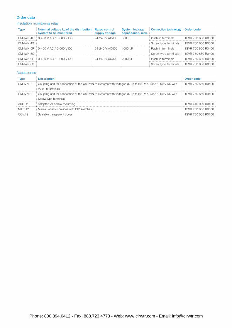
2CDC 251 021 V0012 Data sheet Data sheet Insulation monitoring relays CM-IWN.4/5/6 For unearthed AC, DC and mixed AC/DC systems up to U n = 400 V AC and 600 V DC The CM-IWN serves to monitor insulation resistance in accordance with IEC 61557-8 in unearthed IT AC systems, IT AC systems with galvanically connected DC circuits, or unearthed IT DC systems with a voltage up to 400 V AC and 600 V DC. The measuring range can be extended up to 690 V AC and 1000 V DC by using the coupling unit CM-IVN. It can be configured to the requirements of the applications and therefore used multi-functional. All devices are available with two different terminal versions. You can choose between the proven screw connection technology (double-chamber cage connection terminals) and the completely tool-free Easy Connect Technology (push-in terminals). Characteristics – For monitoring the insulation resistance of unearthed IT systems up to U n = 400 V AC and 600 V DC – According to IEC/EN 61557-8 “Electrical safety in low voltage distribution systems up to 1000 V a.c. and 1500 V d.c. – Equipment for testing, measuring or monitoring of protective measures – Part 8: Insulation monitoring devices for IT systems" 1) – Specifically for applications with high system leakage capacitances, for example in photovoltaic environments – Rated control supply voltage 24-240 V AC/DC – Prognostic measuring principle with superimposed square wave signal – Two measuring ranges 1-100 kΩ and 2-200 kΩ – One (1 x 2 c/o) or two (2 x 1 c/o) threshold values R an 1/ R1 1) (warning) and R an 2/R2 2) (prewarning) configurable 3) – Precise adjustment of the threshold values in 1 kΩ steps (R1) and 2 kΩ steps (R2) – Interrupted wire detection configurable – Non-volatile fault storage configurable – Open- or closed-circuit principle configurable – Precise adjustment by front-face operating controls – Screw connection technology or Easy Connect Technology available Approvals A UL 508, CAN/CSA C22.2 No.14 K IEC/EN 60947-5-1, CB scheme E GB14048.5 - 2001, CCC R EAC L RMRS Marks a CE b RCM – Housing material for highest fire protection classification UL 94 V-0 – Tool-free mounting on DIN rail as well as demounting – 45 mm (1,77 in) width – 3 LEDs for the indication of operational states 1) CM-IWN.6 does not meet the requirements of IEC/EN 61557-8 regarding the response time t an . 2) term acc. to IEC/EN 61557-8 3) R2 only active with 2 x 1 c/o configuration Phone: 800.894.0412 - Fax: 888.723.4773 - Web: www.clrwtr.com - Email: [email protected]
Transcript
2CD
C 2
51 0
21 V
0012
Data sheetData sheet
Insulation monitoring relays CM-IWN.4/5/6For unearthed AC, DC and mixed AC/DC systems up to Un = 400 V AC and 600 V DC
The CM-IWN serves to monitor insulation
resistance in accordance with IEC 61557-8 in
unearthed IT AC systems, IT AC systems with
galvanically connected DC circuits, or unearthed
IT DC systems with a voltage up to 400 V AC and
600 V DC. The measuring range can be extended
up to 690 V AC and 1000 V DC by using the
coupling unit CM-IVN. It can be configured to the
requirements of the applications and therefore
used multi-functional.
All devices are available with two different terminal
versions. You can choose between the proven
screw connection technology (double-chamber
cage connection terminals) and the completely
tool-free Easy Connect Technology (push-in
terminals).
Characteristics – For monitoring the insulation resistance of unearthed
IT systems up to Un = 400 V AC and 600 V DC – According to IEC/EN 61557-8 “Electrical safety in low
voltage distribution systems up to 1000 V a.c. and 1500 V d.c. – Equipment for testing, measuring or monitoring of protective measures – Part 8: Insulation monitoring devices for IT systems"1)
– Specifically for applications with high system leakage capacitances, for example in photovoltaic environments
– Rated control supply voltage 24-240 V AC/DC – Prognostic measuring principle with superimposed square
wave signal – Two measuring ranges 1-100 kΩ and 2-200 kΩ – One (1 x 2 c/o) or two (2 x 1 c/o) threshold values Ran1/
R11) (warning) and Ran2/R22) (prewarning) configurable3)
– Precise adjustment of the threshold values in 1 kΩ steps (R1) and 2 kΩ steps (R2)
– Interrupted wire detection configurable – Non-volatile fault storage configurable – Open- or closed-circuit principle configurable – Precise adjustment by front-face operating controls – Screw connection technology or
Easy Connect Technology available
Approvals
A UL 508, CAN/CSA C22.2 No.14
K IEC/EN 60947-5-1, CB scheme
E GB14048.5 - 2001, CCC
R EAC
L RMRS
Marks
a CE
b RCM
– Housing material for highest fire protection classification UL 94 V-0
– Tool-free mounting on DIN rail as well as demounting – 45 mm (1,77 in) width – 3 LEDs for the indication of operational states
1) CM-IWN.6 does not meet the requirements of IEC/EN 61557-8 regarding the response time tan.2) term acc. to IEC/EN 61557-83) R2 only active with 2 x 1 c/o configuration
Maintenance free Easy Connect Technology with push-in terminals
Type designation CM-xxN.yyP
Approved screw connection technology with double-chamber cage connection terminals
Type designation CM-xxN.yyS
Push-in terminals
– Tool-free connection of rigid and flexible wires with wire end ferrule according to DIN 46228-1-A, DIN 46228-4-E Wire size: 2 x 0.5-1.5 mm², (2 x 20 - 16 AWG)
– Easy connection of flexible wires without wire end ferrule by opening the terminals
– No retightening necessary – One operation lever for opening both connection
terminals – For triggering the lever and disconnecting of wires
you can use the same tool (Screwdriver according to DIN ISO 2380-1 Form A 0.8 x 4 mm (0.0315 x 0.157 in), DIN ISO 8764-1 PZ1 ø 4.5 mm (0.177 in))
– Constant spring force on terminal point independent of the applied wire type, wire size or ambient conditions (e. g. vibrations or temperature changes)
– Opening for testing the electrical contacting – Gas-tight
Double-chamber cage connection terminals
– Terminal spaces for different wire sizes: fine-strand with/without wire end ferrule: 1 x 0.5-2.5 mm² (2 x 20 - 14 AWG), 2 x 0.5-1.5 mm² (2 x 20 - 16 AWG) rigid: 1 x 0.5-4 mm² (1 x 20 - 12 AWG), 2 x 0.5-2.5 mm² (2 x 20 - 14 AWG)
– One screw for opening and closing of both cages – Pozidrive screws for pan- or crosshead screwdrivers
according to DIN ISO 2380-1 Form A 0.8 x 4 mm (0.0315 x 0.157 in), DIN ISO 8764-1 PZ1 ø 4.5 mm (0.177 in)
Both the Easy Connect Technology with push-in terminals and screw connection technology with double-chamber cage connection terminals have the same connection geometry as well as terminal position.
1 Front-face rotary switches to adjust the threshold value:
R1.1 for R1 tens figure: 0, 10, 20, 30, 40, 50, 60, 70, 80, 90 kΩ in ten kΩ steps
R1.2 for R1 units figure: 1, 2, 3, 4, 5, 6, 7, 8, 9, 10 kΩ in one kΩ steps
R2.1 for R2 tens figure: 0, 20, 40, 60, 80, 100, 120, 140, 160, 180 kΩ in twenty kΩ steps
R2.2 for R2 units figure: 2, 4, 6, 8, 10, 12, 14, 16, 18, 20 kΩ in two kΩ steps
2 Test and reset button
3 Indication of operational states
U: green LED – control supply voltage
F1: red LED – fault message
F2: yellow LED – relay status
4 DIP switches (see DIP switch functions)
Application / monitoring function
The CM-IWN serves to monitor insulation resistance in accordance with IEC 61557-8 in unearthed IT AC systems, IT AC systems with galvanically connected DC circuits, or unearthed IT DC systems.
The insulation resistance between system lines and system earth is measured. If this falls below the adjustable threshold values, the output relays switch into the fault state.
The device can monitor control circuits (single-phase) and main circuits (3-phase).
Supply systems with voltages Un = 0-400 V AC (15-400 Hz) or 0-600 V DC can be directly connected to the measuring inputs and their insulation resistance being monitored. For systems with voltages above 400 V AC and 600 V DC the coupling unit CM-IVN can be used for the expansion of the CM-IWN voltage range.
Measuring principle
A pulsating measuring signal is fed into the system to be monitored and the insulation resistance calculated.
This pulsating measuring signal alters its form depending on the insulation resistance and system leakage capacitance. From this altered form the change in the insulation resistance is forecast.
When the forecast insulation resistance corresponds to the insulation resistance calculated in the next measurement cycle and is smaller than the set threshold value, the output relays are activated or deactivated, depending on the device configuration. This measuring principle is also suitable for the detection of symmetrical insulation faults.
Additional monitoring functions
When interrupted wire detection u is activated, the CM-IWN automatically controls the system/measuring circuit connections L+ and L- when the system starts up. This can be repeated at any time by activating the test function. The CM-IWN cyclically monitors the measuring circuit connections w and KE for wire interruption. In case of a wire interruption in one of the connections, the output relays switch to the fault state.
In addition, the unearthed AC-, DC- or AC/DC system is monitored for inadmissible system leakage capacitance. If the system leakage capacitance is too high, the output relays switch to the fault state.
Also incorrect settings that could cause a faulty function of the device are monitored. When the device detects such an incorrect setting, the output relays switch to the fault state.
The system to be monitored is connected to terminals L+ and L-. The earth potential is connected to terminals w and KE.
Depending on the setting, the device operates according to the open-circuit principle h (fault state: relay energized) or closed-circuit principle g (fault state: relay de-energized).
Once the control supply voltage has been applied the insulation monitoring relay runs through a system test routine. The system is diagnosed and the settings are tested. If no internal or external faults are found after this test routine is completed, the output relays switch into the operational state.
All operating states are signalled by the front-face LEDs. See table "LEDs, status information and fault messages" on page 10.
Configuration 1 x 2 c/o contacts j (warning)
With this configuration the settings for the threshold value for prewarning (R2) have no influence on the operating function. If the measured value drops below the set threshold value, the output relays switch into the fault state. If the measured value exceeds the threshold value plus hysteresis, the output relays switch back into their original state.
Configuration 2 x 1 c/o contact i (prewarning and warning)
If the measured value drops below the set threshold value for prewarning the second output relay 21-22/24 switches. If the measured value drops below the threshold value for warning, the first output relay 11-12/14 switches.
If the measured value exceeds the threshold value for warning plus hysteresis, the first output relay 11-12/14 switches back into its original state. If the measured value exceeds the threshold value for prewarning plus hysteresis, also the second output relay 21-22/24 switches back to its original state.
Test function
The test function is only possible when there is no fault.
By pressing the front-face combined test/reset button a system test routine is executed. The output relays switch to the fault state as long as the test/reset button is pressed, the control contact S1-S3 is closed or the test functions are processed.
The test function can be activated either with the front-face combined test/reset button or with a remote test button connected as shown in the picture.
S2 S3S1
2CD
C 2
52 1
09 F
0009
Fault storage, reset function and remote reset
When fault storage f is active, the output relays remain in the fault state and only switch back to their original state after the combined test/reset button is pressed or after the remote reset (terminals S2-S3) is activated, and when the insulation resistance is higher than the set threshold value(s) plus hysteresis.
The fault storage is designed non-volatile (remanent). This means that after switch-off and return of the control supply voltage the device returns to the state it was prior to the switch-off until a reset is executed.
Depending on the configuration of DIP switch 2, there are several possibilities of resetting the device, as shown in the picture.
Measuring range expansion by using the coupling unit CM-IVN
The coupling unit CM-IVN serves to connect the CM-IWN to systems up to 690 V AC and 1000 V DC. Terminals VS, V1+, V1- are connections for the coupling unit.
Function descriptions/diagrams
G Control supply voltage not applied / Output contact open / LED OFF
B Control supply voltage applied / Output contact closed / LED ON
A1-A2
S1-S3
S2-S3
ts
11-1211-14
21-2221-24
11-12
21-24
11-14
21-24
Measured value
HysteresisThreshold value
Open-circuit principle h
U: green LED
F: red LED
R: yellow LED
U: green LED
F: red LED
R: yellow LED
2CD
C 2
52 0
27 F
0211
Closed-circuit principle g
ts = Start-up time, see table Typical start-up times
2CD
C 2
52 0
27 F
0211
Insulation resistance monitoring w/o fault storage e, auto reset, 1 x 2 c/o j
A1-A2
S1-S3
S2-S3
tsts
11-1211-14
21-2221-24
11-1211-14
21-2421-24
Measured value
HysteresisThreshold value
Open-circuit principle h
U: green LED
F: red LED
R: yellow LED
U: green LED
F: red LED
R: yellow LED
2CD
C 2
52 0
28 F
0211
Closed-circuit principle g
ts = Start-up time, see table Typical start-up times
2CD
C 2
52 0
28 F
0211
Insulation resistance monitoring with fault storage f, manual reset, 1 x 2 c/o j
Rotary switches R1.1, R1.2, R2.1 and R2.2 (threshold values)
By means of four separate 10 position rotary switches with direct reading scales, the threshold values for the insulation resistance RF of the systems to be monitored can be adjusted.
With the Rx.1 rotary switch the tens figure is set and with the Rx.2 rotary switch the units figure is set. The set threshold value is then the addition of the two values. For example, R1.1 set to 70 and R1.2 set to 8 leads to a threshold value for R1 of 78 kΩ.
DIP switches
Position 4 123
ON
OFF
i u f ghevj
2CD
C 2
52 0
50 F
0b09
ON OFF (default)
DIP switch 1
Operating principle of
the output relays
Closed-circuit principle gIf closed-circuit principle is selected, the output relays are
energized. They de-energize if a fault is occuring.
Open-circuit principle hIf open-circuit principle is selected, the output relays are
de-energized. The energize if a fault is occuring.
DIP switch 2
Non-volatile fault
storage
Fault storage activated (latching) fIf the fault storage function is activated, the output relays
remain in tripped position until a reset is done either by the
front-face button or by the remote reset connection S2-S3.
This function is non-volatile.
Fault storage de-activated (non latching) eIf the fault storage function is de-activated, the output
relays switch back to their original position as soon as the
insulation fault no longer exists.
DIP switch 3
Interrupted wire
detection
Interrupted wire detection activated uWith this configuration, the CM-IWN monitors the wires
connected to L+ and L- for interruptions.
Interrupted wire detection de-activated vWith this configuration the interrupted wire detection is
de-activated.
DIP switch 4
2 x 1 c/o, 1 x 2 c/o2 x 1 c/o (SPDT) contact iIf operating principle 2 x 1 c/o contact is selected, the
output relay R1 (11-12/14) reacts to threshold value R1
(warning) and the output relay R2 (21-22/24) reacts to
threshold value R2 (prewarning)
1 x 2 c/o (SPDT) contacts jIf operating principle 1 x 2 c/o contacts is selected, both
output relays R1 (11-12/14) and R2 (21-22/24) react
synchronously to threshold value R1 (warning). Settings of
the threshold value R2 have no effect on the operation.
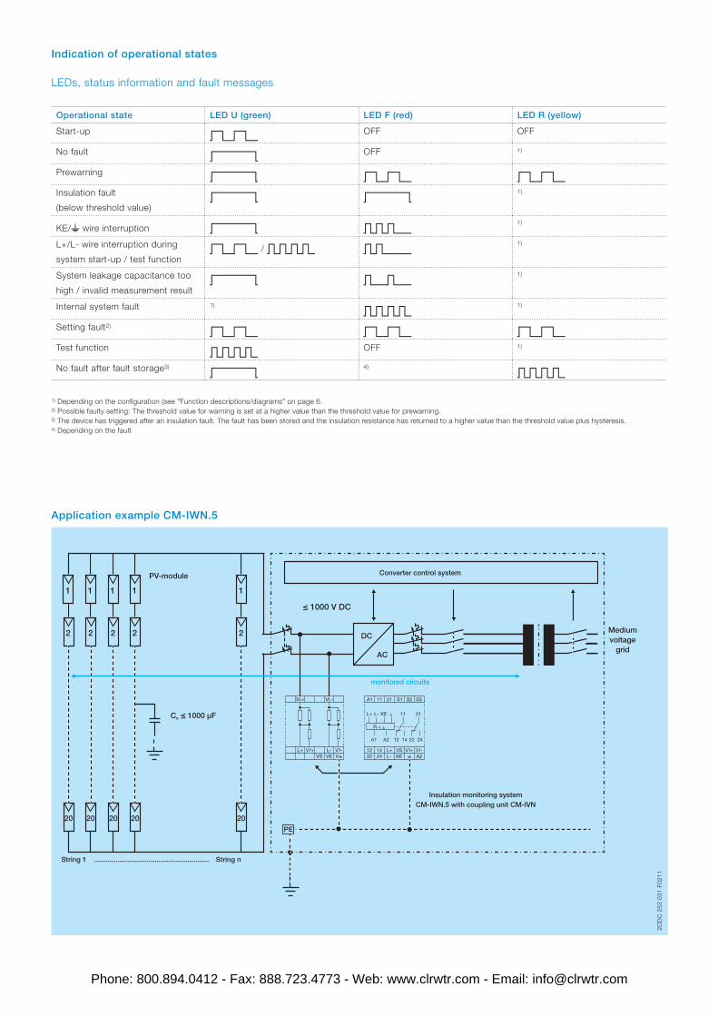
Operational state LED U (green) LED F (red) LED R (yellow)
Start-up W OFF OFF
No fault V OFF 1)
Prewarning V W WInsulation fault
(below threshold value)V V
1)
KE/w wire interruption V U1)
L+/L- wire interruption during
system start-up / test functionW / X S
1)
System leakage capacitance too
high / invalid measurement resultV T
1)
Internal system fault 1)
X1)
Setting fault2)
W W WTest function X OFF 1)
No fault after fault storage3)
V4)
X
1) Depending on the configuration (see "Function descriptions/diagrams" on page 6.2) Possible faulty setting: The threshold value for warning is set at a higher value than the threshold value for prewarning.3) The device has triggered after an insulation fault. The fault has been stored and the insulation resistance has returned to a higher value than the threshold value plus hysteresis.4) Depending on the fault
Application example CM-IWN.5
1 1 1 1
2
1
2222
20 20 20 20 20
Ce ≤ 1000 μF
String 1 ........................................................... String n
PV-module
DC
AC
Medium voltage
grid
A1 11 S2 S321 S1
wL+ VS12 14
A2V1-V1+
KE wL-
A1
R < w
A2
L+
22 24 L- KE
12 14
11
22 24
21
VL+ VL-
VwL-L+VE
V1-V1+VS
≤ 1000 V DC
PE
Insulation monitoring systemCM-IWN.5 with coupling unit CM-IVN
Data at Ta = 25 °C and rated values, unless otherwise indicated
Input circuits
Input circuit - Supply circuit A1 - A2
Rated control supply voltage Us 24-240 V AC/DC Rated control supply voltage tolerance -15...+10 %Typical current / power consumption 24 V DC 55 mA / 1.3 VA
115 V AC 20 mA / 2.3 VA230 V AC 15 mA / 3.5 VA
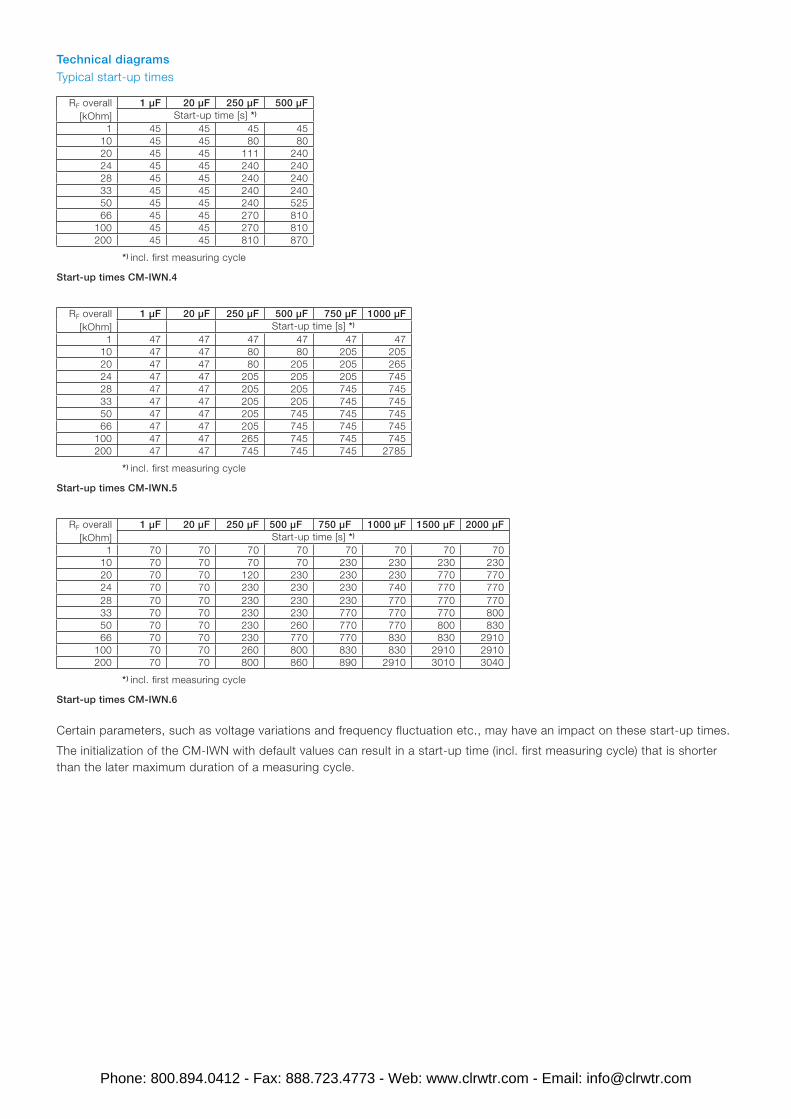
Rated frequency fs DC or 15-400 HzFrequency range AC 13.5-440 HzPower failure buffering time min. 20 msStart-up time ts See „Typical start-up times“ on page 15.
Input circuit - Measuring circuit L+, L-, w, KEMonitoring function insulation resistance monitoring of IT systems
(IEC/EN 61557-8)Measuring principle prognostic measuring principle with superimposed
square wave signal Nominal voltage Un of the distribution system to be monitored 0-400 V AC / 0-600 V DCVoltage range of the distribution system to be monitored 0-460 V AC / 0-690 V DC (tolerance +15 %)Rated frequency fN of the distribution system to be monitored DC or 15-400 HzTolerance of the rated frequency fN 13.5-440 HzSystem leakage capacitance Ce CM-IWN.4 max. 500 µF
CM-IWN.5 max. 1000 µFCM-IWN.6 max. 2000 µF
Extraneous DC voltage Ufg (when connected to an AC system) max. 460 V DC
Voltage range expansion of the measuring input with coupling unit CM-IVN use connection terminals V1+, V1-, VS
max. length of connection cable 40 cmNumber of possible response / threshold values 2Adjustment range of the specified response value Ran
Tolerance of the adjusted threshold value / Relative
percentage uncertainty A
at -5...+45 °C, Un = 0-115 %, Us = 85-110 %, fN, fs,
Ce = 1µF
at 1-15 kΩ RF ±1 kΩ / in combination with CM-IVN ±1.5 kΩat 15-200 kΩ RF ±8 %
Hysteresis related to the threshold value 25 %; min. 2 kΩInternal impedance Zi at 50 Hz 155 kΩInternal DC resistance Ri 185 kΩMeasuring voltage Um 24 VTolerance of measuring voltage Um +10 %Measuring current Im 0.15 mAResponse time tan
pure AC system 0.5 x Ran and Ce = 1 µF max. 10 s (except CM-IWN.6: max. 60 s)DC system or AC system with connected rectifiers max. 15 s (except CM-IWN.6: max. 90 s)
Repeat accuracy (constant parameters) < 0.1 % of full scaleAccuracy of Ra (measured value) within the rated control
supply voltage tolerance
< 0.05 % of full scale
Accuracy of Ra (measured value) within the operation
temperature range
at 1-10 kΩ RF 5 Ω / K
at 10-200 kΩ RF 0.05 % / K
Transient overvoltage protection (w - terminal) avalanche diode
Maximum switching current in the control circuit 1 mAMaximum cable length to the control inputs 50 m - 100 pF/m (164 ft - 30.5 pF/ft)Minimum control pulse length 150 msNo-load voltage at the control input ≤ 24 V DC
User interface
Indication of operational states
Control supply voltage U green LEDFault message F red LEDRelay status R yellow LED
Details see table "LEDs, status information and fault messages" on page 10 and "Function descriptions/diagrams" on page 6.
Operating elements and controls
Adjustment of threshold value R1 R1.1 rotary switch, 10 kΩ steps for the tens figureR1.2 rotary switch, 1 kΩ steps for the units figure
Adjustment of threshold value R2 R2.1 rotary switch, 20 kΩ steps for the tens figureR2.2 rotary switch, 2 kΩ steps for the units figure
Configuration of DIP switch 1 operating principle of the output relaysDIP switch 2 non volatile fault storageDIP switch 3 interrupted wire detectionDIP switch 4 2 x 1 c/o, 1 x 2 c/o
Output circuits
Kind of output 11-12/14
21-22/24
relay, 1st c/o (SPDT) contact
relay, 2nd c/o (SPDT) contact
2 x 1 or 1 x 2 c/o (SPDT) contacts configurable Operating principle open- or closed-circuit principle1) configurableContact material AgNi alloy, Cd freeRated operational voltage (IEC/EN 60947-1) 250 V AC / 300 V DCMinimum switching voltage / Minimum switching current 24 V / 10 mAMaximum switching voltage / Maximum switching current see "Load limits curves" on page 19Rated operational current Ie
(IEC/EN 60947-5-1)
AC12 (resistive) at 230 V 4 AAC15 (inductive) at 230 V 3 A
DC12 (resistive) at 24 V 4 ADC13 (inductive) at 24 V 2 A
AC rating (UL 508) Utilization category
(Control Circuit Rating Code)
B 300, pilot duty general purpose (250 V, 4 A, cos φ 0.75)
max. rated operational voltage 250 V ACmax. continuous thermal current at B 300 4 A
max. making/breaking apparent
power at B 300
3600/360 VA
Mechanical lifetime 30 x 106 switching cyclesElectrical lifetime AC12, 230 V, 4 A 0.1 x 10⁶ switching cyclesMax. fuse rating to achieve short-circuit protection n/c contact 6 A fast-acting
n/o contact 10 A fast-acting
Conventional thermal current Ith (IEC/EN 60947-1) 4 A
1) Closed-circuit principle: Output relay(s) de-energize(s) if measured value falls below the adjusted threshold value Ran
Open-circuit principle: Output relay(s) energize(s) if measured value falls below the adjusted threshold value Ran
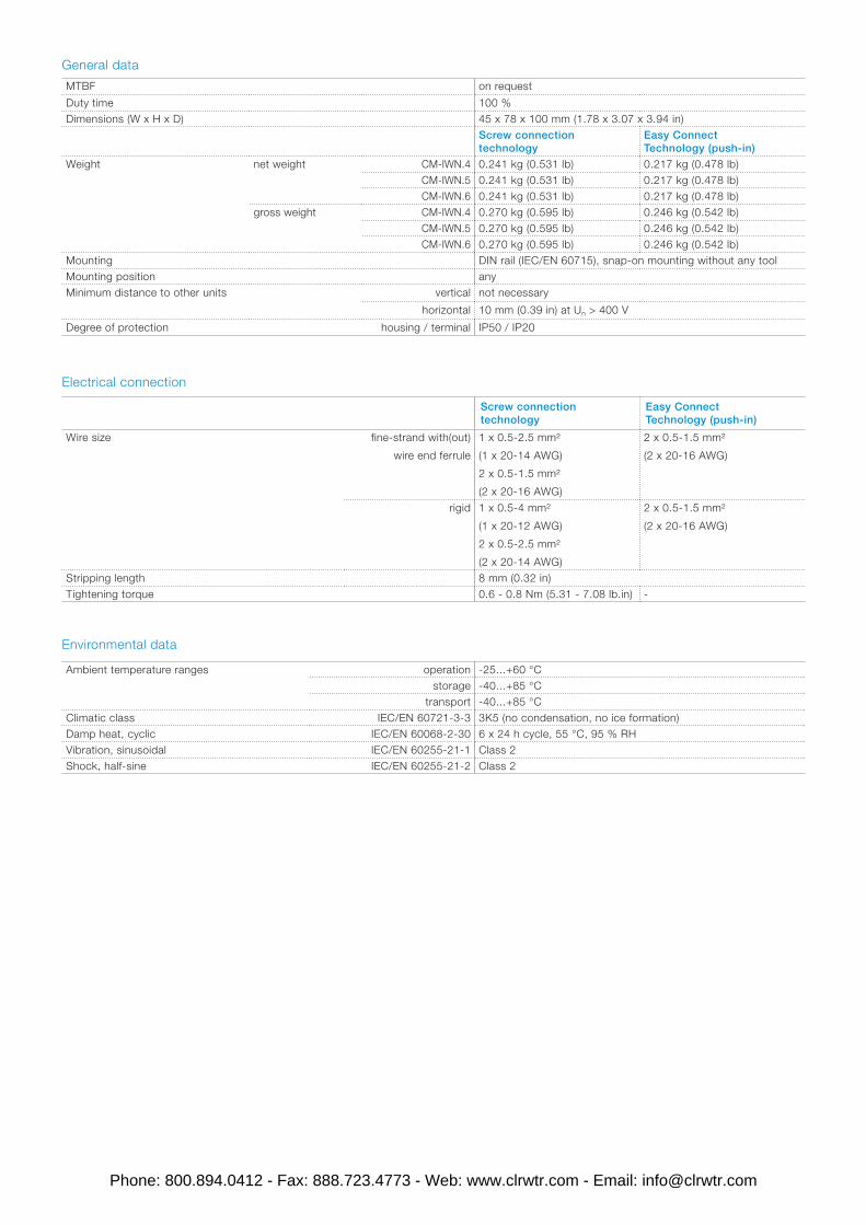
Duty time 100 %Dimensions (W x H x D) 45 x 78 x 100 mm (1.78 x 3.07 x 3.94 in)
Screw connection technology
Easy Connect Technology (push-in)
Weight net weight CM-IWN.4 0.241 kg (0.531 lb) 0.217 kg (0.478 lb)CM-IWN.5 0.241 kg (0.531 lb) 0.217 kg (0.478 lb)CM-IWN.6 0.241 kg (0.531 lb) 0.217 kg (0.478 lb)
gross weight CM-IWN.4 0.270 kg (0.595 lb) 0.246 kg (0.542 lb)CM-IWN.5 0.270 kg (0.595 lb) 0.246 kg (0.542 lb)CM-IWN.6 0.270 kg (0.595 lb) 0.246 kg (0.542 lb)
Mounting DIN rail (IEC/EN 60715), snap-on mounting without any toolMounting position anyMinimum distance to other units vertical not necessary
horizontal 10 mm (0.39 in) at Un > 400 V
Degree of protection housing / terminal IP50 / IP20
Ambient temperature ranges operation -25...+60 °Cstorage -40...+85 °C
transport -40...+85 °CClimatic class IEC/EN 60721-3-3 3K5 (no condensation, no ice formation)Damp heat, cyclic IEC/EN 60068-2-30 6 x 24 h cycle, 55 °C, 95 % RHVibration, sinusoidal IEC/EN 60255-21-1 Class 2Shock, half-sine IEC/EN 60255-21-2 Class 2
Certain parameters, such as voltage variations and frequency fluctuation etc., may have an impact on these start-up times.
The initialization of the CM-IWN with default values can result in a start-up time (incl. first measuring cycle) that is shorter than the later maximum duration of a measuring cycle.
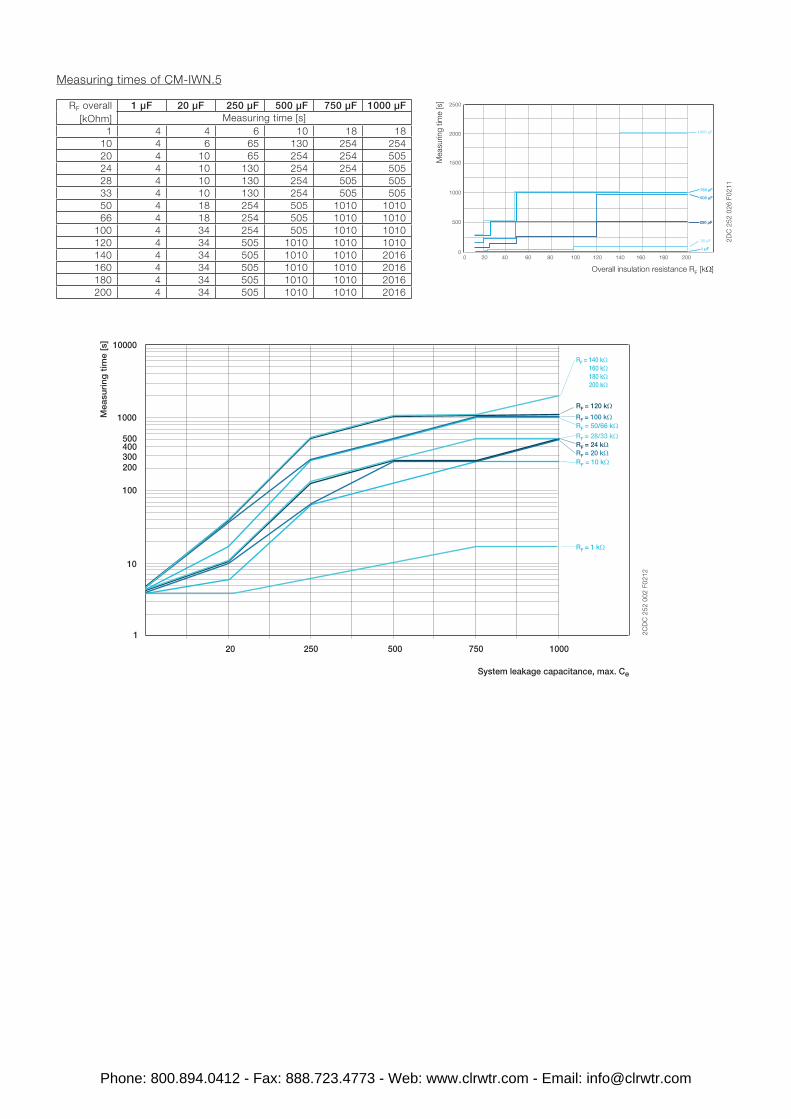
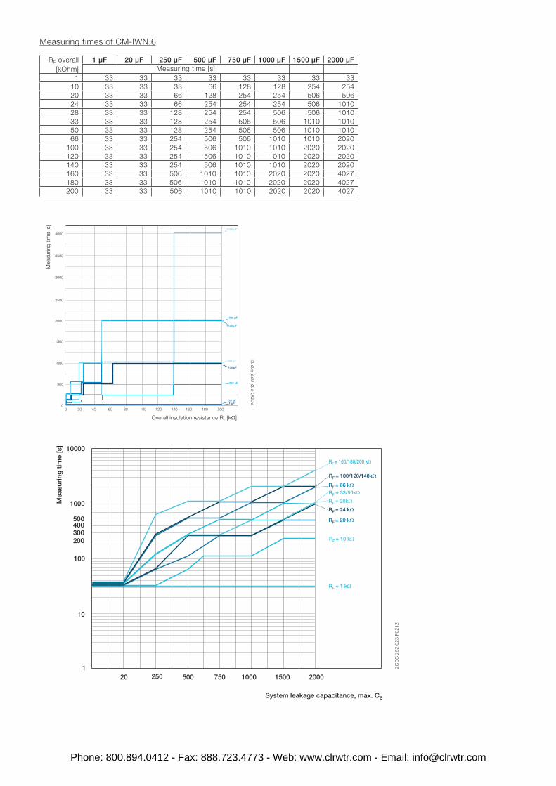
The indicated time values are the pure measuring times in a stable system, not considering the start-up times. Certain parameters, such as voltage variations and frequency fluctuation etc., may have an impact on these measuring times.
When an insulation fault occurs, the maximum reaction time until the output relays switch is 2 times the typical measuring time, provided that no other parameters in the system change.
You can find the documentation on the internet at ABB website -> Control Products -> Electronic Relays and Controls -> Insulation Monitors.
CAD system files
You can find the CAD files for CAD systems at ABB website -> Low Voltage Products & Systems -> Control Products -> Electronic Relays and Controls -> Insulation Monitors