34
© ABB Inc. PTMV - 1 ABB Inc. Medium Voltage Motor Control Center Customer Presentation

©AB
B In
c. P
TMV
-1
ABB Inc.Medium VoltageMotor Control Center
Customer Presentation

©AB
B In
c. P
TMV
-2
Outline
Product Introduction
Product Description
Product Application
Competition
Target Market

©AB
B In
c. P
TMV
-3
Product Introduction

©AB
B In
c. P
TMV
-4
Medium Voltage Motor Control Centers
Medium voltage motor control centers (MVMCC) are devices used in switching loads such as motors, transformers and capacitors.
MVMCCs employ circuit breakers, power monitoring devices and programmable controllers in order to provide appropriate overload protection.

©AB
B In
c. P
TMV
-5
IntroductionABB Medium Voltage Motor Control Center…
The ABB MVMCC design greatly improves maintenance simplicity. The enhancements in this product provide a superior solution for motor control for increased worker safety, enhanced reliability and ease of use.
ANSI rated – constructed in accordance with UL 347
Designed for:
Flexible application -
with a variety of configurations
Operation & safety -
with interlocks & shielding
Maintenance simplicity -
with window to view components
Effective space utilization -
with ample cable space

©AB
B In
c. P
TMV
-6
A Quick Overview
Complete range of ratings of 2.4 to 6.6 kV at 400 A and 720 AApplications for
Full voltage (reversing and non-reversing)Reduce voltage autotransformer starterReduce voltage reactor transformerInduction/ Synchronous (brush or brushless starter)Available options:
Transition sections for close coupling to ABB SafeGear and Advance switchgearAuxiliary section for larger cable entry applicationsPT draw-out compartment
One and two high fully rated stackable modulesVersatile configurationsCompact footprint (30” wide x 44” deep x 95” high)Available arc resistance construction in model 2

©AB
B In
c. P
TMV
-7
Advance Center Main features
Manually operated isolation switch designViewing window for visual verification of switch position as well as for viewing fuse trip indicators without opening the cellRemovable contactor.Manual secondary disconnectCPT fixed mounted for primary and secondary fuse protection100% front accessibilityRoom for cable stress cones (without bending cable)High CT accuracy class (C10, CA100)

©AB
B In
c. P
TMV
-8
Product Description

©AB
B In
c. P
TMV
-9
Product DescriptionModular Design – adapted technology
Similar building blocks used in ABB SafeGear and Advance switchgear Bolted construction enables faster replacement and modification in the fieldAllows for easy replacements, repairs, and specialized configurationsMaintains the smallest, compact product

©AB
B In
c. P
TMV
-10
Product DescriptionEnclosure
NEMA 1, 1A for indoor or 3R non walk-in for outdoorPre-coated Galvalume material throughout for superior resistance to corrosion, self-healing characteristics and makes for a bright interiorHem bends throughout construction greatly reducing exposure to sharp edges
Bus bar:100% front access for easy inspection1200 A, 2000 A, 3000 A with 50kA short circuit400 A or 800 A vertical busSilver plated copper bus standard, Tin plating is availableInsulated bus available Joints covered with reusable boots, removable for inspection and maintenance

©AB
B In
c. P
TMV
-11
Product DescriptionIsolation Switch
Safety device to isolates contactor compartment from main busManual operated from the front with the door closed to avoid inadvertent operationInterlocks prevents:
isolation switch operation when the contactor is closedopening cell door when switch is closedisolation switch operation when the cell door is open
A Lexan shield covers the isolation switch
providing protection from high voltage componentsShutters not needed
Switch position viewable through the cell viewing window – allowing for visible break

©AB
B In
c. P
TMV
-12
Product DescriptionContactor
Removable with automatic primary disconnect and manual secondary disconnect
Vacuum interrupting
400 A, 720 A inside the cubicle
Magnetic or mechanically held
Power FusesFront vertical mounted fuses;clip or bolted
Anti single phase fuse trip available upon request
Fuse trip indicator viewable with door closed
Type R for motor and E for transformer applications
Fuse puller not needed for removal
©AB
B In
c. P
TMV
-13
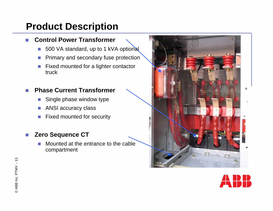
Product DescriptionControl Power Transformer
500 VA standard, up to 1 kVA optionalPrimary and secondary fuse protectionFixed mounted for a lighter contactor truck
Phase Current Transformer Single phase window typeANSI accuracy classFixed mounted for security
Zero Sequence CTMounted at the entrance to the cable compartment

©AB
B In
c. P
TMV
-14
Product DescriptionPower Cable Space
Enhanced cable allocation provides 23” clearance from the bottom of each cell for shielded cable and stress cones
A lexan shield protects terminal blocks and allows for visual inspection
Top or Bottom cable entry
Sufficient space for routing cables with no hard bends
One 500MCM cable maximum per phase

©AB
B In
c. P
TMV
-15
Product DescriptionLV Compartment
Completely isolated LV instrument compartment for utmost safety
No instruments on contactor door
Easy access for operation and maintenance to all control and protection devices
Available in three sizes
19”, 38”, and 57”
Pre-coated Galvalume material makes for a bright interior
Configuration400 A 2-high with fully rated upper and lower cells
720 A 1-high

©AB
B In
c. P
TMV
-16
Product Summary
SafetyHem bending process - eliminates sharp edgesLV components completely isolated from HV componentsIsolation switch and redundant interlocks for protection
Maintenance/ Ease of use Ample cable spaceModular design
Reduces replacing costReduces downtime
Durability Design based on metal clad switchgearHem bending process - Increases rigidityGalvalume material – highly resistive to corrosion
Local service

©AB
B In
c. P
TMV
-17
Contactor Ratings

©AB
B In
c. P
TMV
-18
Contactor Ratings

©AB
B In
c. P
TMV
-19
Product Application

©AB
B In
c. P
TMV
-20
Product ApplicationsFVNR Full Voltage Non Reverse
FVR Full Voltage Reverse
RVAT Reduce Voltage Autotransformer Starter
RVRT Reduce Voltage Reactor Transformer
Synchronous, brush or brushless starter
Medium power capacitor banks
Available arc resistance construction in model 2
Available options:Transition sections for close coupling to switchgear
Auxiliary section for larger cable entry applications
PT draw-out compartment

©AB
B In
c. P
TMV
-21
Product ApplicationsInduction/Synchronous medium and large motors
Blowers, Fans, Conveyors, Pumps, Compressors, Expanders/extruders

©AB
B In
c. P
TMV
-22
Product Applications
Medium Power Transformers
Auxiliary services, MV Solid State Drivers/Starters
Medium Power Capacitor Banks
Improve Power Factor
System Voltage 3 Phase Transformer
3 Phase Capacitor
2.2-2.5 kV 1500 kVA 1500 kVAR3.0-3.3 kV 2000 kVA 2000 kVAR4.0-5.0 kV 3000 kVA 2000 kVAR6.0-6.6 kV 4000 kVA 2000 kVAR

©AB
B In
c. P
TMV
-23
ABB motor protection from basic to high range solutions

©AB
B In
c. P
TMV
-24
Common causes for motor damage and means of protection

©AB
B In
c. P
TMV
-25
Motor Protection Relay REM 610

©AB
B In
c. P
TMV
-26
Motor Protection Relay REM 610
Protection functionsThermal overload protection (49)Temperature supervision based on RTDs (49/38)Motor startup supervision (48)Cumulative motor start-up time counter (66)Short-circuit protection (50)Overcurrent protection (51)Earth-fault protection (50N/51N)Phase unbalance / phase reversal protection (46)Undercurrent (loss of load) protection (37)Circuit-breaker failure protection (62BF)Electrically latched lockout relay (86)Emergency restart

©AB
B In
c. P
TMV
-27
Motor Protection Relay REM 610
Measurements & DisplayPhase & residual current (RMS)
Negative phase sequence current
Display of measured values in primary units
Motor stress during start-up
Temperature via RTDs
Disturbance recorder data (RAM, battery backup)
Self-supervision and alarms
Communication ProtocolsSPA bus communication (via front and rear port )
IEC 60870-103-5 communication (via rear port only)
Modbus communication (via rear port only)

©AB
B In
c. P
TMV
-28
Motor Protection Relay REM 610
Withdrawable mechanical designEasy to install and handleAutomatic short-circuiting of CT secondariesCommunication maintained even when relay unit withdrawnMechanical coding for identification of plug-in unitEasy mounting - no loose mounting accessoriesBoth compression type connection and ring-lug terminal connection of CT secondary wiresIP 54 degree of protection by enclosure of the relay case whenflush-mounted.

©AB
B In
c. P
TMV
-29
Motor Protection Relay REM 610

©AB
B In
c. P
TMV
-30
Motor Protection Relay REM 543

©AB
B In
c. P
TMV
-31
Motor Protection Relay REM 543

©AB
B In
c. P
TMV
-32
Motor Protection Relay REM 543
©AB
B In
c. P
TMV
-33
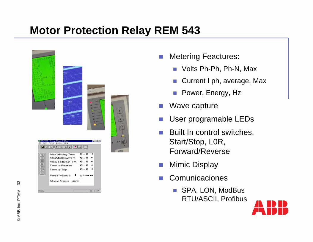
Motor Protection Relay REM 543
Metering Feactures:Volts Ph-Ph, Ph-N, Max
Current I ph, average, Max
Power, Energy, Hz
Wave capture
User programable LEDs
Built In control switches. Start/Stop, L0R, Forward/Reverse
Mimic Display
ComunicacionesSPA, LON, ModBusRTU/ASCII, Profibus

©AB
B In
c. P
TMV
-34


