24
— ABB MEASUREMENT & ANALYTICS | DATA SHEET Endura AZ40 Oxygen and carbon monoxide equivalent (COe) analyzer
—ABB MEASUREMENT & ANALYTICS | DATA SHEET
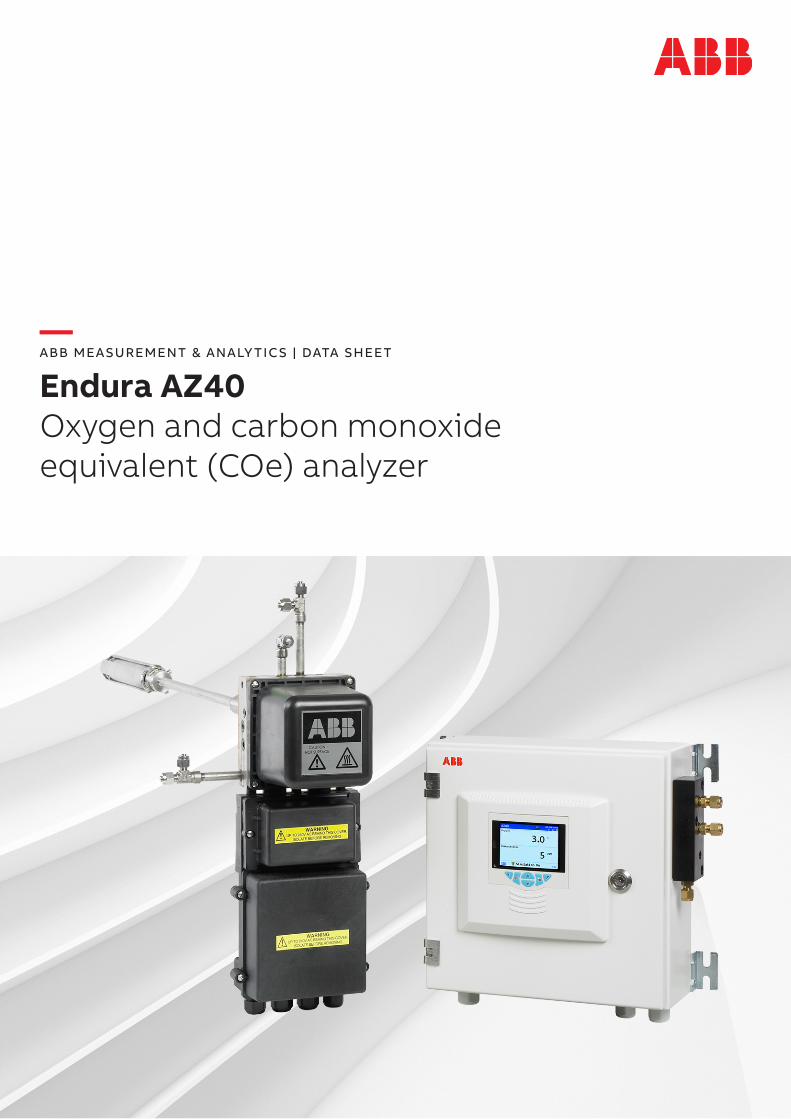
Endura AZ40Oxygen and carbon monoxide equivalent (COe) analyzer
2 ENDUR A AZ40 OXYGEN AND CARBON MONOXIDE EQUIVALENT (COE) ANALYZER | DS/AZ40-EN REV. C
—Measurement made easy Superior technology and quality from the world leader in combustion gas analysis—Oxygen only or oxygen plus combustibles• increased combustion efficiency• burner malfunction identification• enhanced plant safety
—Close-coupled sample system• integral flame arrestors• stable sample temperature and pressure• heated sample path
—Comprehensive diagnostics• NAMUR-compliant diagnostic symbols• supports predictive maintenance• fully logged diagnostic events
—Automatic sensor calibration• fully programmable schedule• locally triggered
—Process logging and trending of all measured andcalculated values• oxygen and carbon monoxide equivalent (COe)• process temperature measurement• combustion efficiency calculation
3ENDUR A AZ40 OXYGEN AND CARBON MONOXIDE EQUIVALENT (COE) ANALYZER | DS/AZ40-EN REV. C
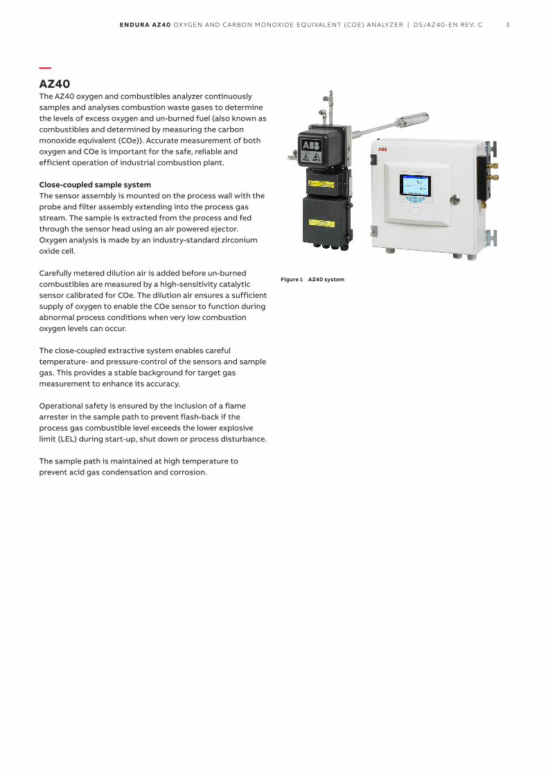
—AZ40The AZ40 oxygen and combustibles analyzer continuously samples and analyses combustion waste gases to determine the levels of excess oxygen and un-burned fuel (also known as combustibles and determined by measuring the carbon monoxide equivalent (COe)). Accurate measurement of both oxygen and COe is important for the safe, reliable and efficient operation of industrial combustion plant.
Close-coupled sample systemThe sensor assembly is mounted on the process wall with the probe and filter assembly extending into the process gas stream. The sample is extracted from the process and fed through the sensor head using an air powered ejector. Oxygen analysis is made by an industry-standard zirconium oxide cell.
Carefully metered dilution air is added before un-burned combustibles are measured by a high-sensitivity catalytic sensor calibrated for COe. The dilution air ensures a sufficient supply of oxygen to enable the COe sensor to function during abnormal process conditions when very low combustion oxygen levels can occur.
The close-coupled extractive system enables careful temperature- and pressure-control of the sensors and sample gas. This provides a stable background for target gas measurement to enhance its accuracy.
Operational safety is ensured by the inclusion of a flame arrester in the sample path to prevent flash-back if the process gas combustible level exceeds the lower explosive limit (LEL) during start-up, shut down or process disturbance.
The sample path is maintained at high temperature to prevent acid gas condensation and corrosion.
Figure 1 AZ40 system
4 ENDUR A AZ40 OXYGEN AND CARBON MONOXIDE EQUIVALENT (COE) ANALYZER | DS/AZ40-EN REV. C
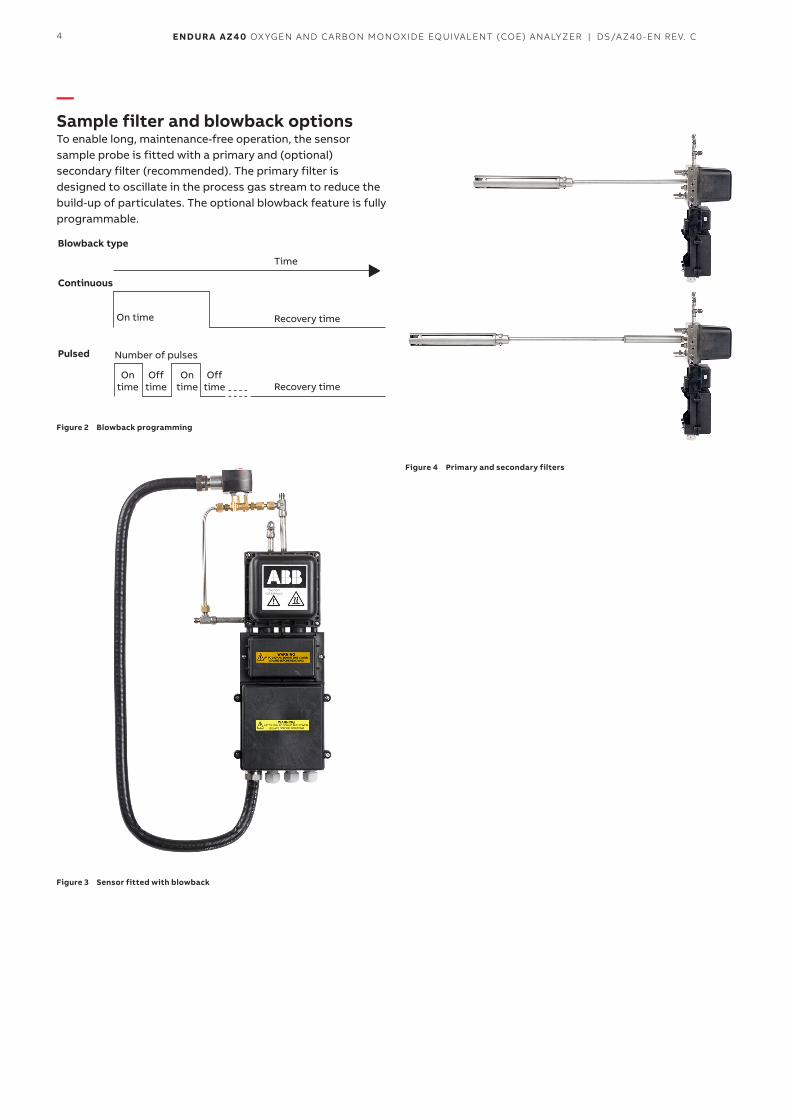
—Sample filter and blowback optionsTo enable long, maintenance-free operation, the sensor sample probe is fitted with a primary and (optional) secondary filter (recommended). The primary filter is designed to oscillate in the process gas stream to reduce the build-up of particulates. The optional blowback feature is fully programmable.
Blowback type
Continuous
Pulsed
Time
On time
On time
Off time
On time
Off time
Number of pulses
Recovery time
Recovery time
Figure 2 Blowback programming
Figure 3 Sensor fitted with blowback
Figure 4 Primary and secondary filters
5ENDUR A AZ40 OXYGEN AND CARBON MONOXIDE EQUIVALENT (COE) ANALYZER | DS/AZ40-EN REV. C
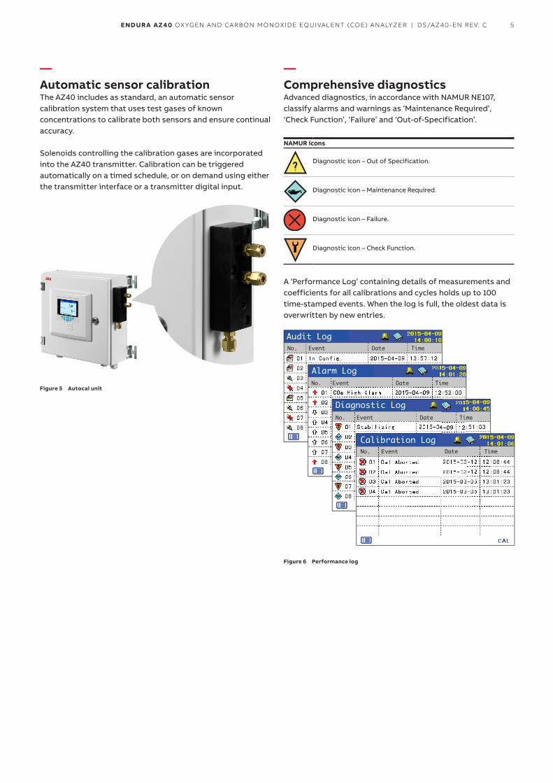
—Automatic sensor calibrationThe AZ40 includes as standard, an automatic sensor calibration system that uses test gases of known concentrations to calibrate both sensors and ensure continual accuracy.
Solenoids controlling the calibration gases are incorporated into the AZ40 transmitter. Calibration can be triggered automatically on a timed schedule, or on demand using either the transmitter interface or a transmitter digital input.
Figure 5 Autocal unit
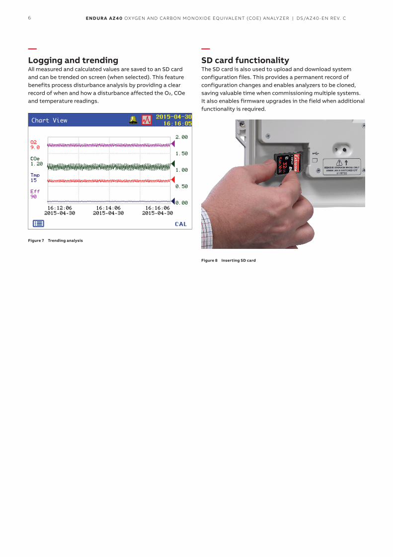
—Comprehensive diagnosticsAdvanced diagnostics, in accordance with NAMUR NE107, classify alarms and warnings as ‘Maintenance Required’, ‘Check Function’, ‘Failure’ and ‘Out-of-Specification’.
NAMUR icons
Diagnostic icon – Out of Specification.
Diagnostic icon – Maintenance Required.
Diagnostic icon – Failure.
Diagnostic icon – Check Function.
A ‘Performance Log’ containing details of measurements and coefficients for all calibrations and cycles holds up to 100 time-stamped events. When the log is full, the oldest data is overwritten by new entries.
Audit Log
Alarm Log
Diagnostic Log
Calibration LogNo. Event Date Time
No. Event Date Time
No. Event Date Time
No. Event Date Time
Figure 6 Performance log
6 ENDUR A AZ40 OXYGEN AND CARBON MONOXIDE EQUIVALENT (COE) ANALYZER | DS/AZ40-EN REV. C
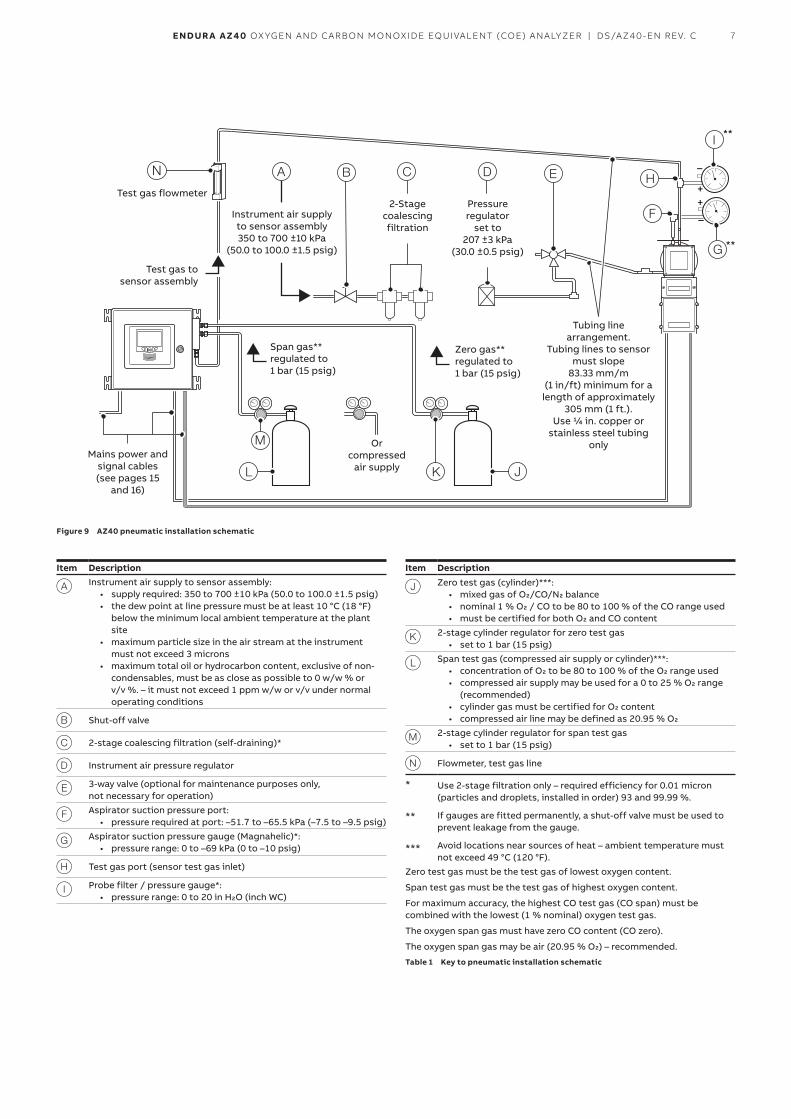
—Logging and trendingAll measured and calculated values are saved to an SD card and can be trended on screen (when selected). This feature benefits process disturbance analysis by providing a clear record of when and how a disturbance affected the O2, COe and temperature readings.
Chart View
Figure 7 Trending analysis
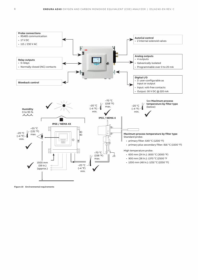
—SD card functionalityThe SD card is also used to upload and download system configuration files. This provides a permanent record of configuration changes and enables analyzers to be cloned, saving valuable time when commissioning multiple systems. It also enables firmware upgrades in the field when additional functionality is required.
Figure 8 Inserting SD card
7ENDUR A AZ40 OXYGEN AND CARBON MONOXIDE EQUIVALENT (COE) ANALYZER | DS/AZ40-EN REV. C
+
–
+
–
**
**
Test gas flowmeter
Test gas to sensor assembly
Instrument air supply to sensor assembly 350 to 700 ±10 kPa
(50.0 to 100.0 ±1.5 psig)
2-Stage coalescing filtration
Pressure regulator
set to 207 ±3 kPa
(30.0 ±0.5 psig)
Tubing line arrangement.
Tubing lines to sensor must slope
83.33 mm/m (1 in/ft) minimum for a length of approximately
305 mm (1 ft.). Use 1/4 in. copper or
stainless steel tubing only
Zero gas** regulated to 1 bar (15 psig)
Span gas** regulated to 1 bar (15 psig)
Or compressed
air supplyMains power and
signal cables (see pages 15
and 16)
Figure 9 AZ40 pneumatic installation schematic
Item Description
A Instrument air supply to sensor assembly:• supply required: 350 to 700 ±10 kPa (50.0 to 100.0 ±1.5 psig)• the dew point at line pressure must be at least 10 °C (18 °F)
below the minimum local ambient temperature at the plant site
• maximum particle size in the air stream at the instrument must not exceed 3 microns
• maximum total oil or hydrocarbon content, exclusive of non-condensables, must be as close as possible to 0 w/w % or v/v %. – it must not exceed 1 ppm w/w or v/v under normal operating conditions
B Shut-off valve
C 2-stage coalescing filtration (self-draining)*
D Instrument air pressure regulator
E 3-way valve (optional for maintenance purposes only, not necessary for operation)
F Aspirator suction pressure port:• pressure required at port: –51.7 to –65.5 kPa (–7.5 to –9.5 psig)
G Aspirator suction pressure gauge (Magnahelic)*: • pressure range: 0 to –69 kPa (0 to –10 psig)
H Test gas port (sensor test gas inlet)
I Probe filter / pressure gauge*: • pressure range: 0 to 20 in H2O (inch WC)
Item Description
J Zero test gas (cylinder)***:• mixed gas of O2/CO/N2 balance• nominal 1 % O2 / CO to be 80 to 100 % of the CO range used• must be certified for both O2 and CO content
K 2-stage cylinder regulator for zero test gas• set to 1 bar (15 psig)
L Span test gas (compressed air supply or cylinder)***:• concentration of O2 to be 80 to 100 % of the O2 range used• compressed air supply may be used for a 0 to 25 % O2 range
(recommended)• cylinder gas must be certified for O2 content• compressed air line may be defined as 20.95 % O2
M 2-stage cylinder regulator for span test gas• set to 1 bar (15 psig)
N Flowmeter, test gas line
* Use 2-stage filtration only – required efficiency for 0.01 micron (particles and droplets, installed in order) 93 and 99.99 %.
** If gauges are fitted permanently, a shut-off valve must be used to prevent leakage from the gauge.
*** Avoid locations near sources of heat – ambient temperature must not exceed 49 °C (120 °F).
Zero test gas must be the test gas of lowest oxygen content.
Span test gas must be the test gas of highest oxygen content.
For maximum accuracy, the highest CO test gas (CO span) must be combined with the lowest (1 % nominal) oxygen test gas.
The oxygen span gas must have zero CO content (CO zero).
The oxygen span gas may be air (20.95 % O2) – recommended.
Table 1 Key to pneumatic installation schematic
8 ENDUR A AZ40 OXYGEN AND CARBON MONOXIDE EQUIVALENT (COE) ANALYZER | DS/AZ40-EN REV. C
Probe connections• RS485 communication
• 17 V DC
• 115 / 230 V AC
AutoCal control• 2 internal solenoid valves
Relay outputs• 6 relays
• Normally closed (NC) contacts
Humidity0 to 95 %
IP66 / NEMA 4X
IP55 / NEMA 4
–20 °C (–4 °F)
min.
–20 °C (–4 °F)
min.
–20 °C (–4 °F)
min.
–20 °C (–4 °F)
min.
1500 mm (59 in.)
(approx.)
–70 °C (158 °F) max.
–55 °C (131 °F) max.
–70 °C (158 °F) max.
See Maximum process temperature by filter type (below)
Maximum process temperature by filter typeStandard probe:
• primary filter: 649 °C (1200 °F)
• primary plus secondary filter: 816 °C (1500 °F)
High temperature probe:
• 600 mm (24 in.): 1650 °C (3000 °F)
• 900 mm (36 in.): 1370 °C (2500 °F
• 1200 mm (48 in.): 1232 °C (2250 °F)
Analog outputs• 4 outputs
• Galvanically isolated
• Programmable over 0 to 20 mA
Blowback control
Digital I/O• 2: user-configurable as
input or output
• Input: volt-free contacts
• Output: 30 V DC @ 220 mA
Figure 10 Environmental requirements
9ENDUR A AZ40 OXYGEN AND CARBON MONOXIDE EQUIVALENT (COE) ANALYZER | DS/AZ40-EN REV. C
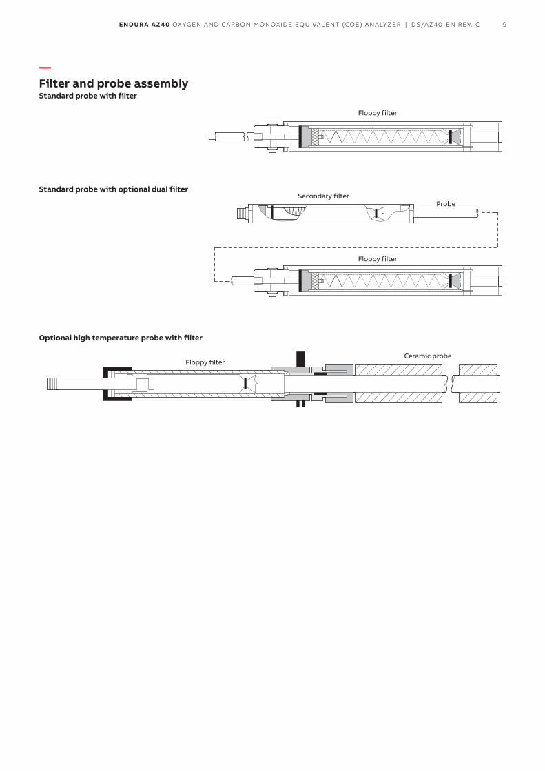
—Filter and probe assemblyStandard probe with filter
Floppy filter
Floppy filter
Floppy filterCeramic probe
Secondary filterProbe
Standard probe with optional dual filter
Optional high temperature probe with filter
10 ENDUR A AZ40 OXYGEN AND CARBON MONOXIDE EQUIVALENT (COE) ANALYZER | DS/AZ40-EN REV. C
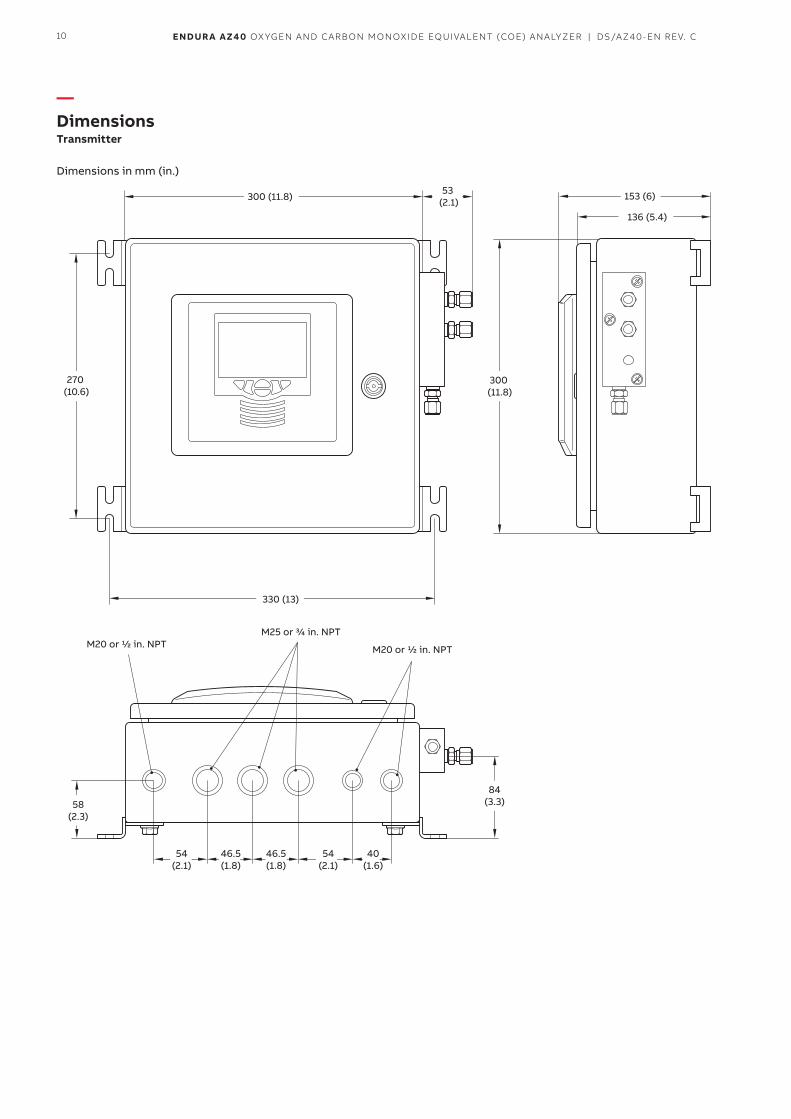
—DimensionsTransmitter
Dimensions in mm (in.)
300 (11.8) 153 (6)
136 (5.4)
300 (11.8)
270 (10.6)
330 (13)
53 (2.1)
84(3.3)
54(2.1)
46.5(1.8)
46.5(1.8)
54(2.1)
40(1.6)
58(2.3)
M25 or 3/4 in. NPTM20 or 1/2 in. NPT M20 or 1/2 in. NPT
11ENDUR A AZ40 OXYGEN AND CARBON MONOXIDE EQUIVALENT (COE) ANALYZER | DS/AZ40-EN REV. C
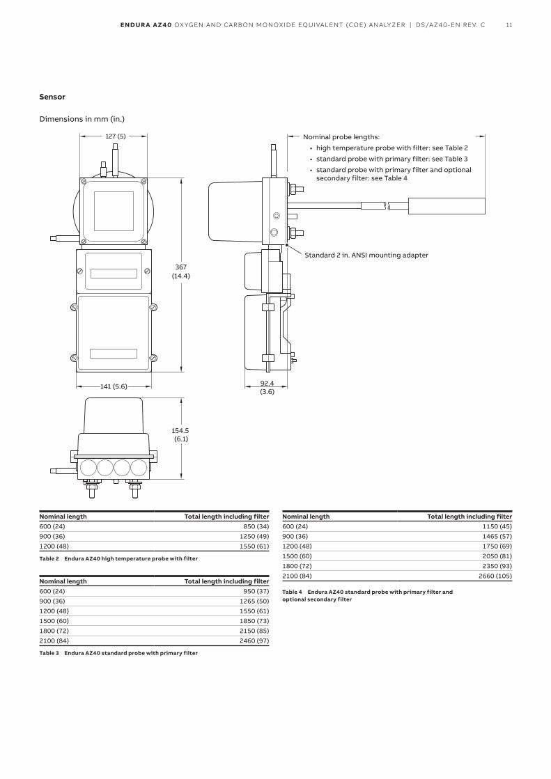
Sensor
Dimensions in mm (in.)
127 (5)
367 (14.4)
141 (5.6)
154.5 (6.1)
92.4(3.6)
Nominal probe lengths:
• high temperature probe with filter: see Table 2
• standard probe with primary filter: see Table 3
• standard probe with primary filter and optional secondary filter: see Table 4
Standard 2 in. ANSI mounting adapter
Nominal length Total length including filter600 (24) 850 (34)900 (36) 1250 (49)1200 (48) 1550 (61)
Table 2 Endura AZ40 high temperature probe with filter
Nominal length Total length including filter600 (24) 950 (37)900 (36) 1265 (50)1200 (48) 1550 (61)1500 (60) 1850 (73)1800 (72) 2150 (85)2100 (84) 2460 (97)
Table 3 Endura AZ40 standard probe with primary filter
Nominal length Total length including filter600 (24) 1150 (45)900 (36) 1465 (57)1200 (48) 1750 (69)1500 (60) 2050 (81)1800 (72) 2350 (93)2100 (84) 2660 (105)
Table 4 Endura AZ40 standard probe with primary filter and optional secondary filter
12 ENDUR A AZ40 OXYGEN AND CARBON MONOXIDE EQUIVALENT (COE) ANALYZER | DS/AZ40-EN REV. C
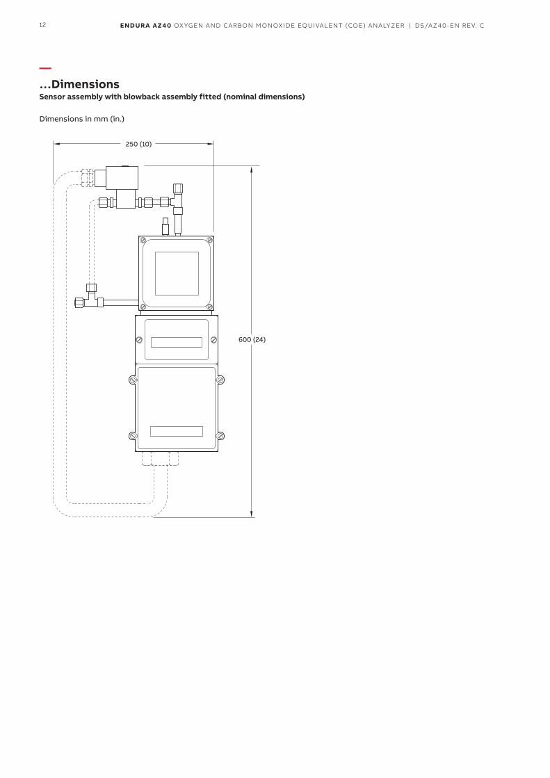
—…DimensionsSensor assembly with blowback assembly fitted (nominal dimensions)
Dimensions in mm (in.)
250 (10)
600 (24)
13ENDUR A AZ40 OXYGEN AND CARBON MONOXIDE EQUIVALENT (COE) ANALYZER | DS/AZ40-EN REV. C
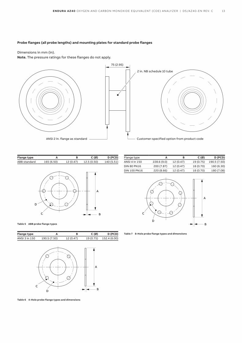
Probe flanges (all probe lengths) and mounting plates for standard probe flanges
Dimensions in mm (in).Note. The pressure ratings for these flanges do not apply.
75 (2.95)
ANSI 2 in. flange as standard Customer-specified option from product code
2 in. NB schedule 10 tube
Flange type A B C (Ø) D (PCD)ABB standard 165 (6.50) 12 (0.47) 12.5 (0.50) 140 (5.51)
A
BC
D
Table 5 ABB probe flange types
Flange type A B C (Ø) D (PCD)ANSI 3 in 150 190.5 (7.50) 12 (0.47) 19 (0.75) 152.4 (6.00)
A
BC
D
Table 6 4-Hole probe flange types and dimensions
Flange type A B C (Ø) D (PCD)ANSI 4 in 150 228.6 (9.0) 12 (0.47) 19 (0.75) 190.5 (7.50)DIN 80 PN16 200 (7.87) 12 (0.47) 18 (0.70) 160 (6.30)DIN 100 PN16 220 (8.66) 12 (0.47) 18 (0.70) 180 (7.08)
A
B
C
D
Table 7 8-Hole probe flange types and dimensions
14 ENDUR A AZ40 OXYGEN AND CARBON MONOXIDE EQUIVALENT (COE) ANALYZER | DS/AZ40-EN REV. C
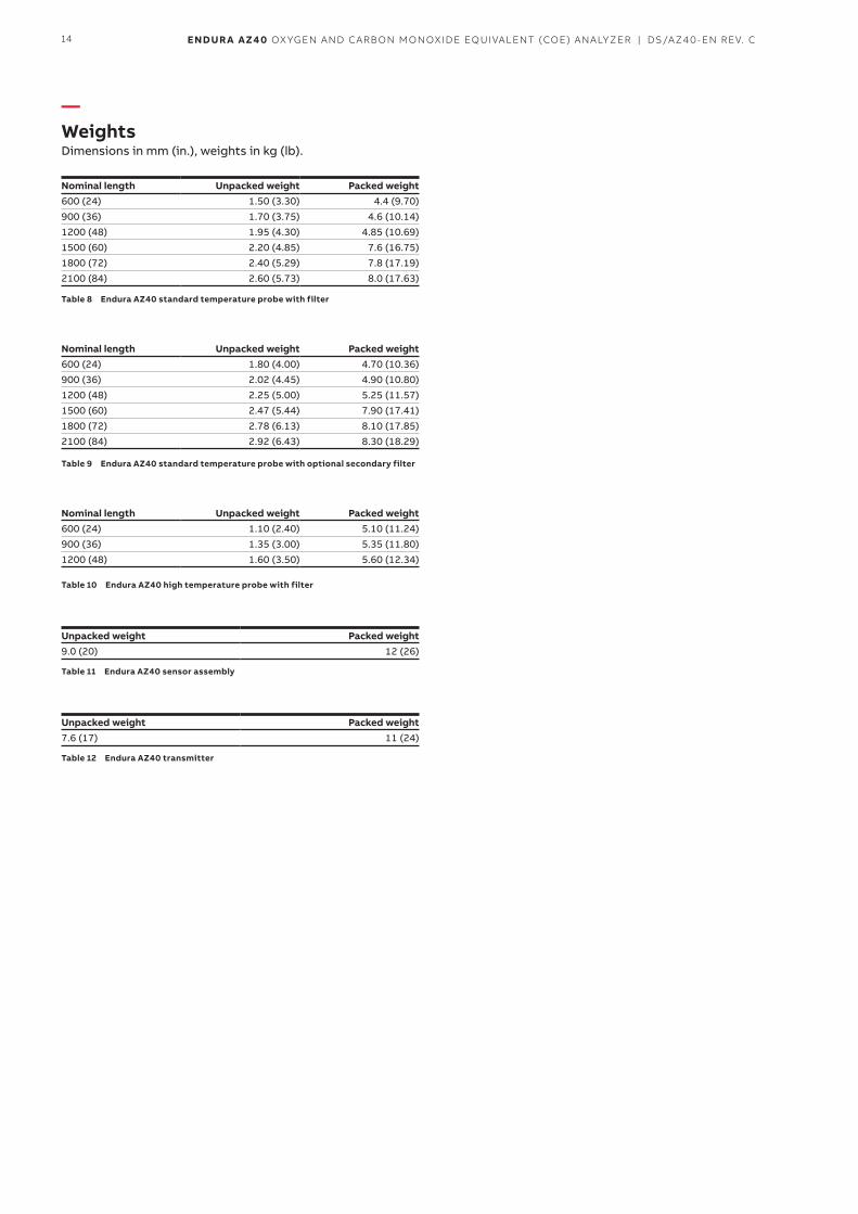
—WeightsDimensions in mm (in.), weights in kg (lb).
Nominal length Unpacked weight Packed weight600 (24) 1.50 (3.30) 4.4 (9.70)900 (36) 1.70 (3.75) 4.6 (10.14)1200 (48) 1.95 (4.30) 4.85 (10.69)1500 (60) 2.20 (4.85) 7.6 (16.75)1800 (72) 2.40 (5.29) 7.8 (17.19)2100 (84) 2.60 (5.73) 8.0 (17.63)
Table 8 Endura AZ40 standard temperature probe with filter
Nominal length Unpacked weight Packed weight600 (24) 1.80 (4.00) 4.70 (10.36)900 (36) 2.02 (4.45) 4.90 (10.80)1200 (48) 2.25 (5.00) 5.25 (11.57)1500 (60) 2.47 (5.44) 7.90 (17.41)1800 (72) 2.78 (6.13) 8.10 (17.85)2100 (84) 2.92 (6.43) 8.30 (18.29)
Table 9 Endura AZ40 standard temperature probe with optional secondary filter
Nominal length Unpacked weight Packed weight600 (24) 1.10 (2.40) 5.10 (11.24)900 (36) 1.35 (3.00) 5.35 (11.80)1200 (48) 1.60 (3.50) 5.60 (12.34)
Table 10 Endura AZ40 high temperature probe with filter
Unpacked weight Packed weight9.0 (20) 12 (26)
Table 11 Endura AZ40 sensor assembly
Unpacked weight Packed weight7.6 (17) 11 (24)
Table 12 Endura AZ40 transmitter
15ENDUR A AZ40 OXYGEN AND CARBON MONOXIDE EQUIVALENT (COE) ANALYZER | DS/AZ40-EN REV. C
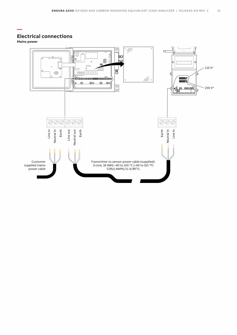
—Electrical connectionsMains power
115 V*
Customer supplied mains
power cable
Transmitter to sensor power cable (supplied). 3-core, 16 AWG –40 to 105 °C (–40 to 221 °F)
C(RU) AWM1/11 A/BFT1
230 V*
Eart
h
Neu
tral
in
Line
in
Line
in
Neu
tral
in
Eart
h
Line
out
Neu
tral
out
Eart
h
16 ENDUR A AZ40 OXYGEN AND CARBON MONOXIDE EQUIVALENT (COE) ANALYZER | DS/AZ40-EN REV. C
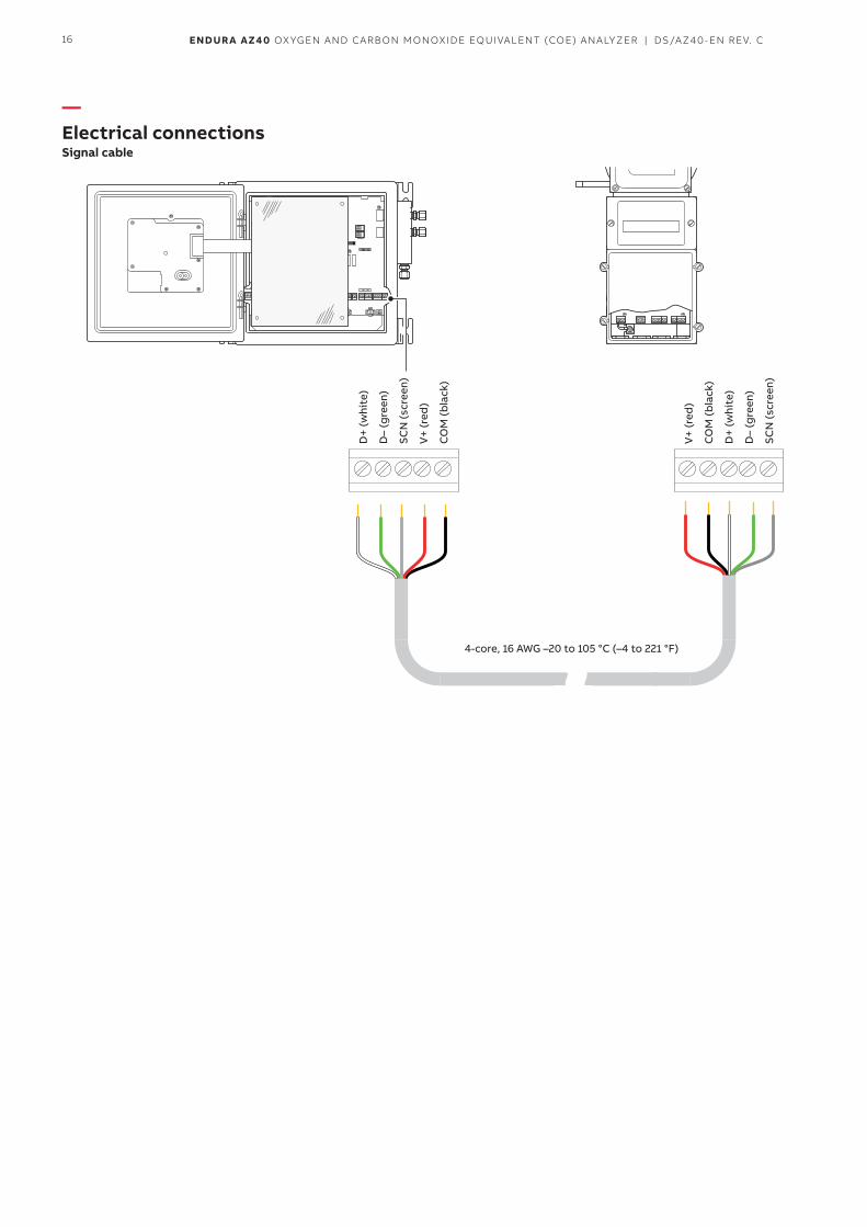
—Electrical connectionsSignal cable
4-core, 16 AWG –20 to 105 °C (–4 to 221 °F)
D+
(whi
te)
D–
(gre
en)
SCN
(scr
een)
V+
(red
)
CO
M (
bla
ck)
V+
(red
)
CO
M (
bla
ck)
D+
(whi
te)
D–
(gre
en)
SCN
(scr
een)
17ENDUR A AZ40 OXYGEN AND CARBON MONOXIDE EQUIVALENT (COE) ANALYZER | DS/AZ40-EN REV. C
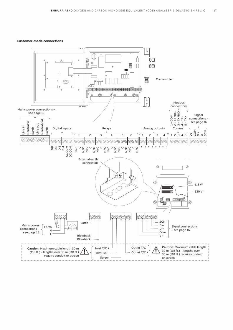
Customer-made connections
SCND –D +ComV +
1 2 3 4 5 V+
CO
MD
+D
–SC
N
N/C C
N/O
N/C C
N/O
N/C C
N/O
N/C C
N/O
N/C C
N/O
N/C C
N/O
1 2 3 4
+ – + – + – + –
DI1
DI2
DI3
DI4
AC
CO
MD
C C
OM
1 2 3 4 5 6
1 –
CO
M
2 –
TX/R
X–
3 –
TX/R
X+
4 –
TX–
5 –
TX+
Mains power connections – see page 15
Mains power connections –
see page 15
Earth N L
Earth
Blowback Blowback
Caution: Maximum cable length 30 m (118 ft.) – lengths over 30 m (118 ft.)
require conduit or screen
Caution: Maximum cable length 30 m (118 ft.) – lengths over 30 m (118 ft.) require conduit or screen
Inlet T/C +
Inlet T/C –
Screen
Outlet T/C –
Outlet T/C +
Digital inputs
External earth connection
115 V*
230 V*
Relays
Signal connections –
see page 16
Signal connections – see page 16
CommsAnalog outputs
Modbus connections
Transmitter
Line
in
Neu
tral
in
Eart
h
Line
out
Neu
tral
out
Eart
h
18 ENDUR A AZ40 OXYGEN AND CARBON MONOXIDE EQUIVALENT (COE) ANALYZER | DS/AZ40-EN REV. C
—SpecificationRangeO2 span
• Minimum 0 to 5 %• Maximum 0 to 25 %
COe span• Minimum 0 to 500 ppm• Maximum 0 to 20,000 ppm (2.00 %)
Temperature zero–46 to 1371 °C (–50 to 2500 °F)
Temperature span• Minimum 260 °C (500 °F)• Maximum 1649 °C (3000 °F)
Sensor response time to 63 % span (t63)O2
< 3.5 secondsCOe
< 13 seconds
Display measurement accuracyO2
±2.5 % of reading or ±0.5 % O2 whichever is greaterCOe
• ±20 ppm COe or ±2 % of selected span whichever is greater (from 200 to 999 ppm)
• ±400 ppm COe or ±2 % of selected span whichever is greater (from 1,000 to 20,000 ppm)
TemperatureThermocouple type B, E, J, K, N, R, S and T
Analog output accuracyO2
±2.5 % of reading or ±0.5 % O2 whichever is greaterCOe
• ±20 ppm COe or ±2 % of selected span whichever is greater (from 200 to 999 ppm)
• ±400 ppm COe or ±2 % of selected span whichever is greater (from 1,000 to 20,000 ppm)
TemperatureThermocouple type B, E, J, K, N, R, S, T
Ambient operating temperatureTransmitter
–20 to 55 °C (–4 to 131 °F)Sensor
–20 to 70 °C (–4 to 158 °F)Interconnecting cable
• Signal: –20 to 105 °C (–4 to 221 °F) • Power: –40 to 105 °C (–40 to 221 °F)
C(RU) AWM1/11 A/BFT1
Storage temperature–40 to 85 °C (–40 to 185 °F)
Operating humidityUp to 95 % RH, non condensing
Ingress protectionTransmitter
IP66 / NEMA 4XSensor
IP55 / NEMA 4
Power supply requirementsSupply voltage
85 to 265 V AC, 50 / 60 HzTransmitter
<60 WSensor
<730 W (during start up) and <310 W (when operating)
EMCEmissions and immunity
EN61326 Industrial specification
SafetyGeneral safety
CE (EN61010)
19ENDUR A AZ40 OXYGEN AND CARBON MONOXIDE EQUIVALENT (COE) ANALYZER | DS/AZ40-EN REV. C
Probe insertion lengthDimensions in mm (in.)
Standard probeNo filter Primary filter Primary and secondary filter600 (24) 950 (37) 1150 (45)900 (36) 1265 (50) 1465 (57)1200 (48) 1550 (61) 1750 (69)1500 (60) 1850 (73) 2050 (81)1800 (72) 2150 (85) 2350 (93)2100 (84) 2460 (97) 2660 (105)
High temperature probeNo filter High temperature filter600 (24) 850 (34)900 (36) 1250 (49)1200 (48) 1550 (61)
Process connectionsStandard / High temperature probes
• ANSI 2 / 3 / 4 in.• DIN 80 / 100
Temperature rangeStandard probe
–20 to 650 °C (0 to 1,200 °F) High temperature probe
–20 to 1650 °C (0 to 3,000 °F)
Maximum process temperature by filter typeStandard probe
Filter type Maximum temperaturePrimary 649 °C (1200 °F)Primary + secondary 816 °C (1500 °F)
High temperature probeProbe length Maximum temperature600 mm (24 in.) 1650 °C (3000 °F)900 mm (36 in.) 1370 °C (2500 °F1200 mm (48 in.) 1232 °C (2250 °F)
Process pressure range±5 kPa (±20 in. WG)
Air supply• 207 kPa at 15 l/min
(standard temperature and pressure)• 30.0 psi at 0.55 SCFM
(standard temperature and pressure)
CalibrationManual or automatic
Automatic calibrationAutoCal hardware
• Built-in solenoid valves for test gas flow• Isolated solenoid valve control as standard,
24 V at 2 W per valve
Blowback functionOptional solenoid valve
Transmitter enclosureWall mount
• Painted stainless steel (approx dimensions – 300 x 300 x 150 mm [11.8 x 11.8 x 5.9 in.])
• Optional NPT or metric gland entries
Display and switchesDisplay type
Backlit, 89 mm (3.5 in.) colorOperator switches
6
Analog outputsNumber
4 (standard)Output 1 to 4
Isolated 0 to 22 mAFunction
• Fixed retransmission functions• O/P 1: process O2• O/P 2: process COe• O/P 3: process temperature• O/P 4: combustion efficiency
20 ENDUR A AZ40 OXYGEN AND CARBON MONOXIDE EQUIVALENT (COE) ANALYZER | DS/AZ40-EN REV. C
—…Specification
Digital outputsNumber
6Type
Normally closed 2 A at 230 V AC (30 V DC non-inductive)Function
Digital output functions• Digital output 1: process alarm O2• Digital output 2: process alarm COe• Digital output 3: process temperature alarm• Digital output 4: combustion efficiency alarm• Digital output 5: analyzer fault alarm• Digital output 6: calibration in progress
Digital inputsNumber
4Input
Volt-free contactInput functions
Fixed functions:• DI 1: remote calibration trigger• DI 2: remote blowback trigger• DI 3: remote zero gas trigger• DI 4: remote span gas trigger
Digital communicationMODBUS
SD card optionLogs
Audit, alarm, calibration and diagnosticsData logging
• COe, O2, inlet and outlet temperature and efficiency• Sample rate programmable between 1 second and 60
minutesConfiguration
Upload / downloadFirmware
Field upgradable
LanguagesEnglish
21ENDUR A AZ40 OXYGEN AND CARBON MONOXIDE EQUIVALENT (COE) ANALYZER | DS/AZ40-EN REV. C
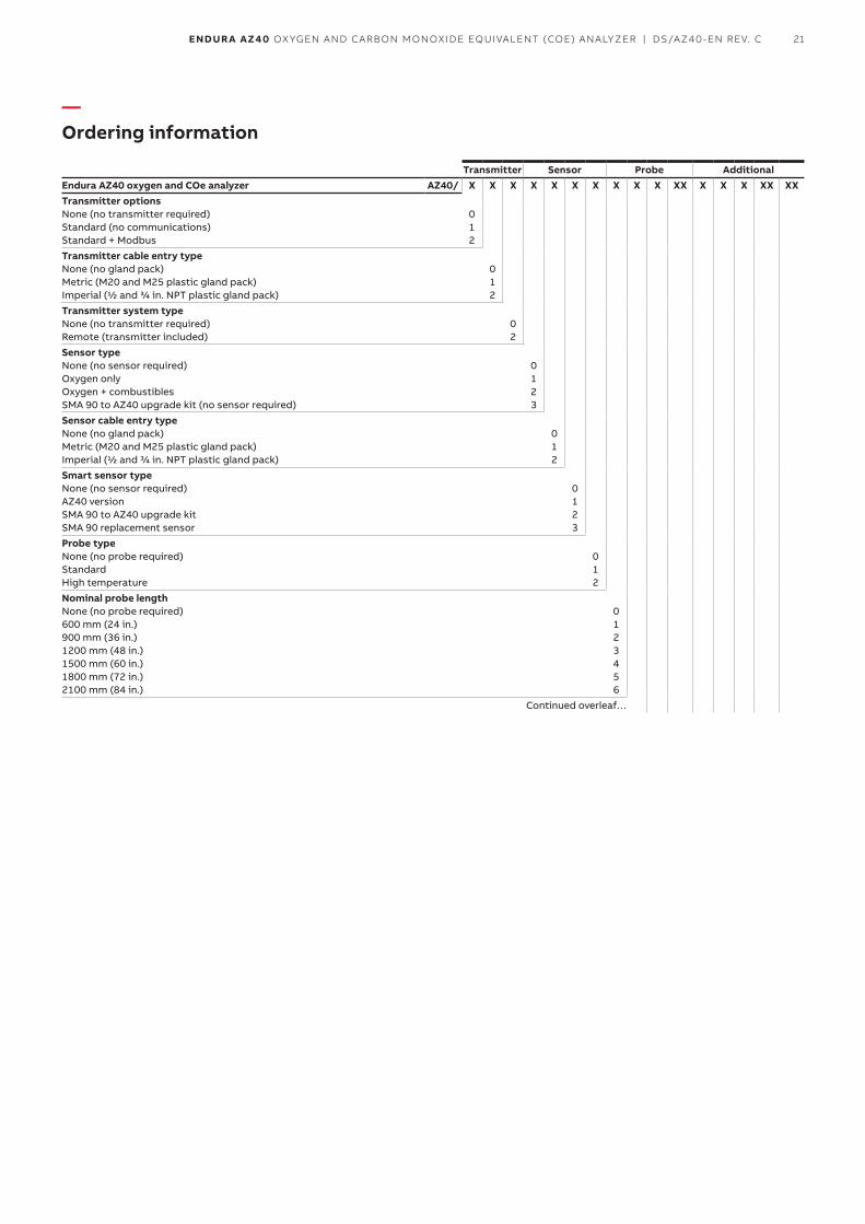
—Ordering information
Transmitter Sensor Probe AdditionalEndura AZ40 oxygen and COe analyzer AZ40/ X X X X X X X X X X XX X X X XX XXTransmitter optionsNone (no transmitter required) Standard (no communications) Standard + Modbus
0 1 2
Transmitter cable entry typeNone (no gland pack) Metric (M20 and M25 plastic gland pack) Imperial (1/2 and 3/4 in. NPT plastic gland pack)
0 1 2
Transmitter system typeNone (no transmitter required) Remote (transmitter included)
0 2
Sensor typeNone (no sensor required) Oxygen only Oxygen + combustibles SMA 90 to AZ40 upgrade kit (no sensor required)
0 1 2 3
Sensor cable entry typeNone (no gland pack) Metric (M20 and M25 plastic gland pack) Imperial (1/2 and 3/4 in. NPT plastic gland pack)
0 1 2
Smart sensor typeNone (no sensor required) AZ40 version SMA 90 to AZ40 upgrade kit SMA 90 replacement sensor
0 1 23
Probe typeNone (no probe required) Standard High temperature
0 1 2
Nominal probe lengthNone (no probe required) 600 mm (24 in.) 900 mm (36 in.) 1200 mm (48 in.) 1500 mm (60 in.) 1800 mm (72 in.) 2100 mm (84 in.)
0 1 2 3 4 5 6
Continued overleaf…
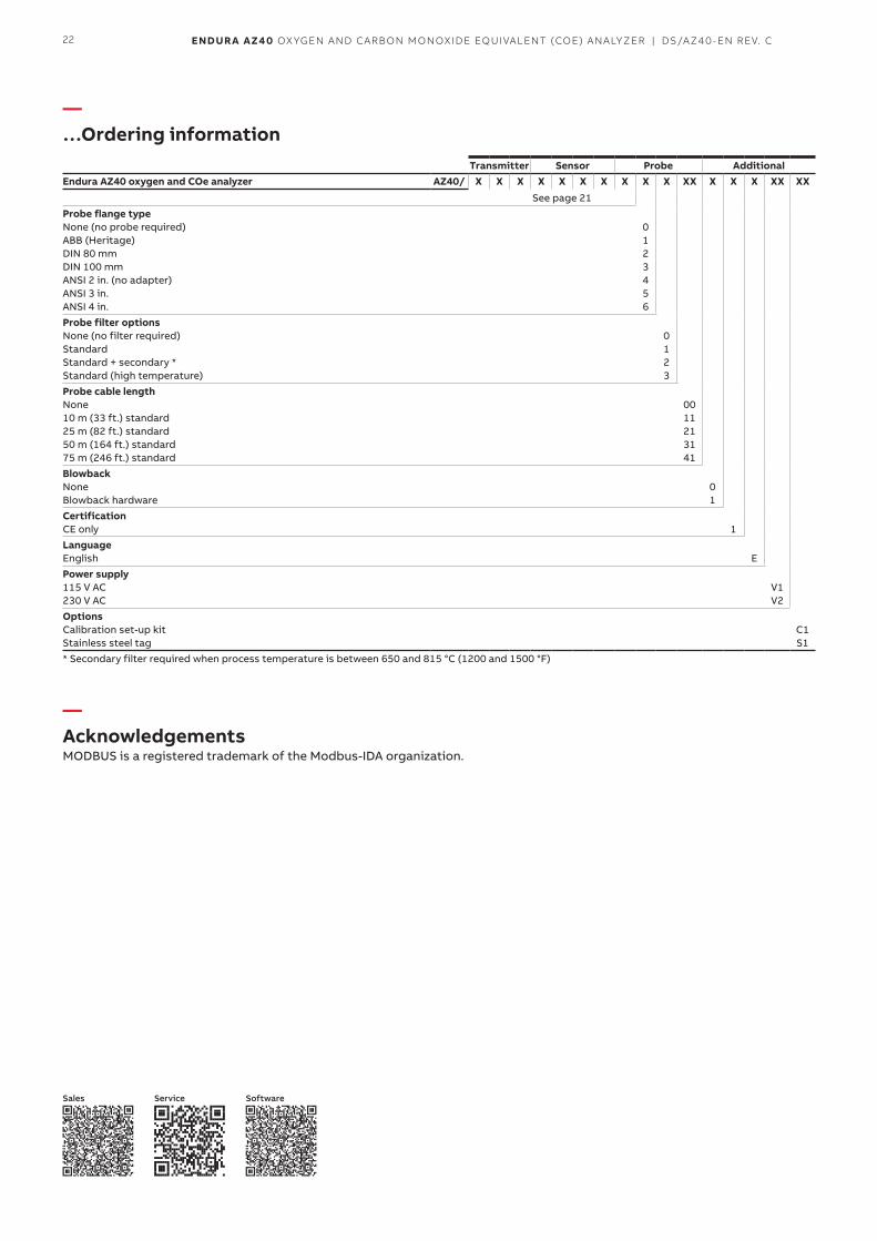
22 ENDUR A AZ40 OXYGEN AND CARBON MONOXIDE EQUIVALENT (COE) ANALYZER | DS/AZ40-EN REV. C
Transmitter Sensor Probe AdditionalEndura AZ40 oxygen and COe analyzer AZ40/ X X X X X X X X X X XX X X X XX XX
See page 21Probe flange typeNone (no probe required) ABB (Heritage) DIN 80 mm DIN 100 mm ANSI 2 in. (no adapter) ANSI 3 in. ANSI 4 in.
0 1 2 3 4 5 6
Probe filter optionsNone (no filter required) Standard Standard + secondary * Standard (high temperature)
0 1 23
Probe cable lengthNone 10 m (33 ft.) standard 25 m (82 ft.) standard 50 m (164 ft.) standard 75 m (246 ft.) standard
00 11 21 31 41
BlowbackNone Blowback hardware
0 1
CertificationCE only 1LanguageEnglish EPower supply115 V AC230 V AC
V1 V2
OptionsCalibration set-up kit Stainless steel tag
C1 S1
* Secondary filter required when process temperature is between 650 and 815 °C (1200 and 1500 °F)
—AcknowledgementsMODBUS is a registered trademark of the Modbus-IDA organization.
Sales Service Software
—…Ordering information

23ENDUR A AZ40 OXYGEN AND CARBON MONOXIDE EQUIVALENT (COE) ANALYZER | DS/AZ40-EN REV. C
DS
/AZ
40
-EN
Rev
. C
11.2
017
—ABB Limited Measurement & AnalyticsOldends Lane Stonehouse Gloucestershire GL10 3TA UK Tel: +44 (0)1453 826 661 Fax: +44 (0)1453 829 671Mail: [email protected]
ABB Limited Measurement & Analytics125 E. County Line Road Warminster PA 18974 USA Tel: +1 215 674 6000 Fax: +1 215 674 7183
abb.com/measurement
We reserve the right to make technical changes or modify the contents of this document without prior notice. With regard to purchase orders, the agreed particulars shall prevail. ABB does not accept any responsibility whatsoever for potential errors or possible lack of information in this document.
We reserve all rights in this document and in the subject matter and illustrations contained therein. Any reproduction, disclosure to third parties or utilization of its contents – in whole or in parts – is forbidden without prior written consent of ABB.
© 2017 ABBAll rights reserved 3KXA722430R1001


