8
— ABB MEASUREMENT & ANALYTICS LiMCA III Liquid Metal Cleanliness Analyzer
— ABB ME A SUREMENT & ANALY TIC S
LiMCA IIILiquid Metal Cleanliness Analyzer
2 LI M C A I I I L I Q U I D M E TA L CL E A N L I N E SS A N A LY ZER
—The LiMCA III is a versatile aluminium cleanliness analyzer that can be used to sample at multiple locations along the casting lines of most casthouses
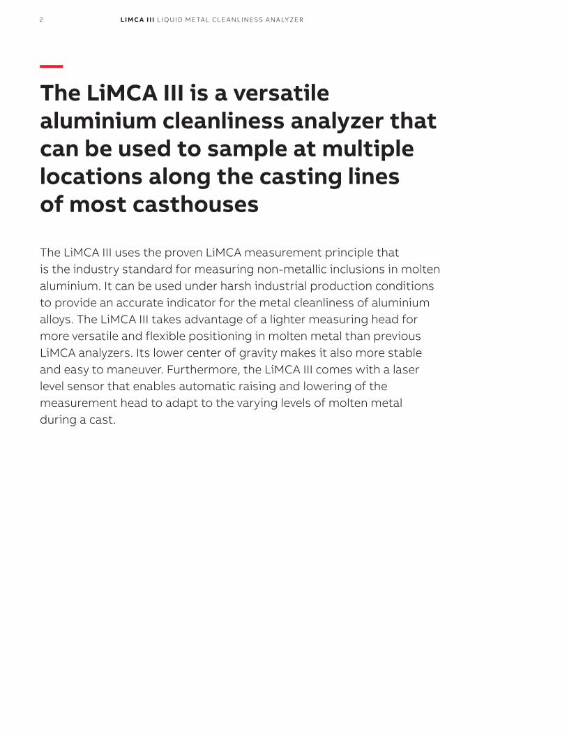
The LiMCA III uses the proven LiMCA measurement principle that is the industry standard for measuring non-metallic inclusions in molten aluminium. It can be used under harsh industrial production conditions to provide an accurate indicator for the metal cleanliness of aluminium alloys. The LiMCA III takes advantage of a lighter measuring head for more versatile and flexible positioning in molten metal than previous LiMCA analyzers. Its lower center of gravity makes it also more stable and easy to maneuver. Furthermore, the LiMCA III comes with a laser level sensor that enables automatic raising and lowering of the measurement head to adapt to the varying levels of molten metal during a cast.
3LI M C A I I I L I Q U I D M E TA L CL E A N L I N E SS A N A LY ZER
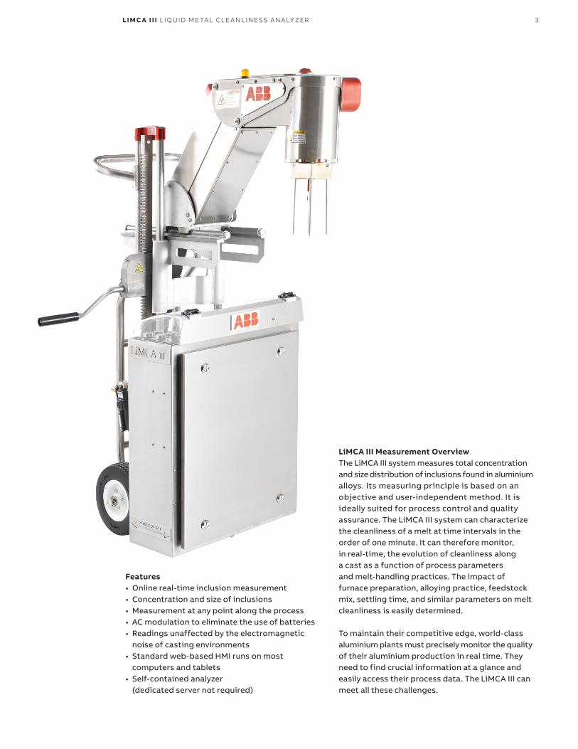
LiMCA III Measurement OverviewThe LiMCA III system measures total concentration and size distribution of inclusions found in aluminium alloys. Its measuring principle is based on an objective and user-independent method. It is ideally suited for process control and quality assurance. The LiMCA III system can characterize the cleanliness of a melt at time intervals in the order of one minute. It can therefore monitor, in real-time, the evolution of cleanliness along a cast as a function of process parameters and melt-handling practices. The impact of furnace preparation, alloying practice, feedstock mix, settling time, and similar parameters on melt cleanliness is easily determined. To maintain their competitive edge, world-class aluminium plants must precisely monitor the quality of their aluminium production in real time. They need to find crucial information at a glance and easily access their process data. The LiMCA III can meet all these challenges.
Features• Online real-time inclusion measurement• Concentration and size of inclusions• Measurement at any point along the process• AC modulation to eliminate the use of batteries• Readings unaffected by the electromagnetic
noise of casting environments• Standard web-based HMI runs on most
computers and tablets• Self-contained analyzer
(dedicated server not required)
4 LI M C A I I I L I Q U I D M E TA L CL E A N L I N E SS A N A LY ZER
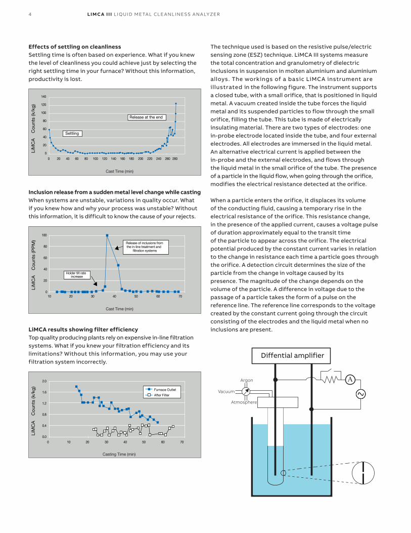
Effects of settling on cleanlinessSettling time is often based on experience. What if you knew the level of cleanliness you could achieve just by selecting the right settling time in your furnace? Without this information, productivity is lost.
Inclusion release from a sudden metal level change while castingWhen systems are unstable, variations in quality occur. What if you knew how and why your process was unstable? Without this information, it is difficult to know the cause of your rejects.
100
80
60
40
20
010 20 30 40 50 60 70
LiM
CA
C
ounts
(PP
M)
Cast Time (min)
Release of inclusions fromthe in-line treatment and
�ltration systems
Holder tilt rateincrease
LiMCA results showing filter efficiencyTop quality producing plants rely on expensive in-line filtration systems. What if you knew your filtration efficiency and its limitations? Without this information, you may use your filtration system incorrectly.
2.0
1.6
1.2
0.8
0.4
0.0
0 10 20 30 40 50 60 70
Furnace Outlet
After Filter
LiM
CA
C
ounts
(k/k
g)
Casting Time (min)
A
Diffential amplifier
Argon
Vacuum
Atmosphere
The technique used is based on the resistive pulse/electric sensing zone (ESZ) technique. LiMCA III systems measure the total concentration and granulometry of dielectric inclusions in suspension in molten aluminium and aluminium alloys. The workings of a basic LiMCA instrument are illustrated in the following figure. The instrument supports a closed tube, with a small orifice, that is positioned in liquid metal. A vacuum created inside the tube forces the liquid metal and its suspended particles to flow through the small orifice, filling the tube. This tube is made of electrically insulating material. There are two types of electrodes: one in-probe electrode located inside the tube, and four external electrodes. All electrodes are immersed in the liquid metal. An alternative electrical current is applied between the in-probe and the external electrodes, and flows through the liquid metal in the small orifice of the tube. The presence of a particle in the liquid flow, when going through the orifice, modifies the electrical resistance detected at the orifice.
When a particle enters the orifice, it displaces its volume of the conducting fluid, causing a temporary rise in the electrical resistance of the orifice. This resistance change, in the presence of the applied current, causes a voltage pulse of duration approximately equal to the transit time of the particle to appear across the orifice. The electrical potential produced by the constant current varies in relation to the change in resistance each time a particle goes through the orifice. A detection circuit determines the size of the particle from the change in voltage caused by its presence. The magnitude of the change depends on the volume of the particle. A difference in voltage due to the passage of a particle takes the form of a pulse on the reference line. The reference line corresponds to the voltage created by the constant current going through the circuit consisting of the electrodes and the liquid metal when no inclusions are present.
5LI M C A I I I L I Q U I D M E TA L CL E A N L I N E SS A N A LY ZER
ARTICLE OR CHAPTER TITLE 5
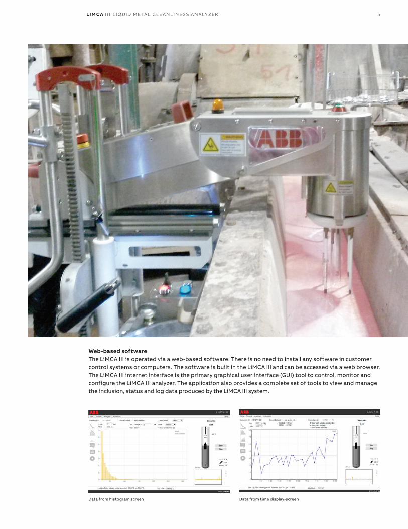
Web-based software The LiMCA III is operated via a web-based software. There is no need to install any software in customer control systems or computers. The software is built in the LiMCA III and can be accessed via a web browser. The LiMCA III internet interface is the primary graphical user interface (GUI) tool to control, monitor and configure the LiMCA III analyzer. The application also provides a complete set of tools to view and manage the inclusion, status and log data produced by the LiMCA III system.
Data from time display-screenData from histogram screen
6 LI M C A I I I L I Q U I D M E TA L CL E A N L I N E SS A N A LY ZER
1
2
3
4
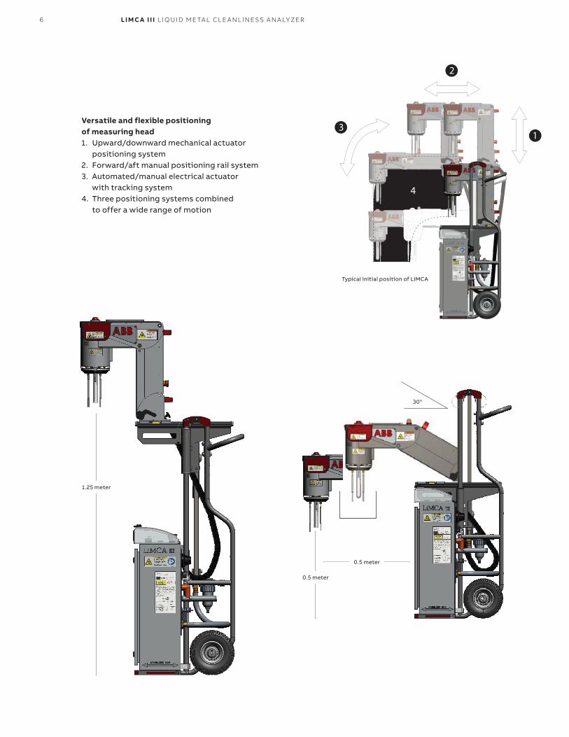
Versatile and flexible positioning of measuring head1. Upward/downward mechanical actuator
positioning system2. Forward/aft manual positioning rail system3. Automated/manual electrical actuator
with tracking system4. Three positioning systems combined
to offer a wide range of motion
1.25 meter
Typical initial position of LiMCA
0.5 meter
0.5 meter
30°
7LI M C A I I I L I Q U I D M E TA L CL E A N L I N E SS A N A LY ZER
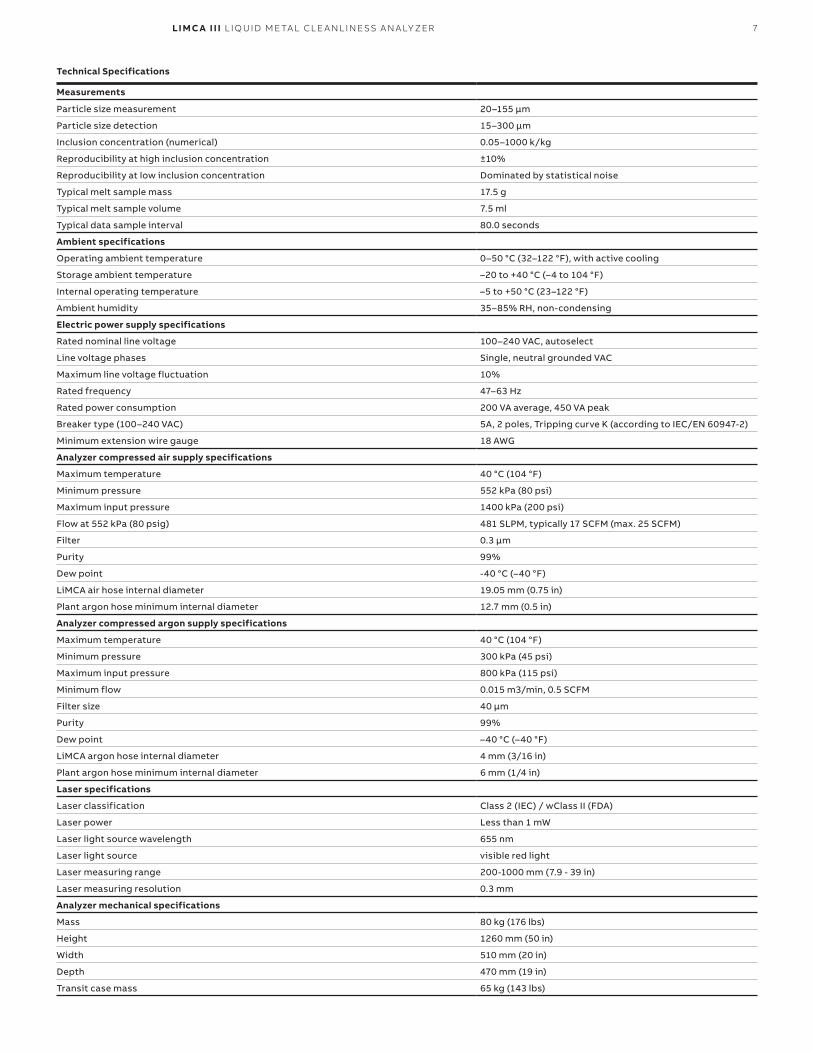
Measurements
Particle size measurement 20–155 µm
Particle size detection 15–300 µm
Inclusion concentration (numerical) 0.05–1000 k/kg
Reproducibility at high inclusion concentration ±10%
Reproducibility at low inclusion concentration Dominated by statistical noise
Typical melt sample mass 17.5 g
Typical melt sample volume 7.5 ml
Typical data sample interval 80.0 seconds
Ambient specifications
Operating ambient temperature 0–50 °C (32–122 °F), with active cooling
Storage ambient temperature –20 to +40 °C (–4 to 104 °F)
Internal operating temperature –5 to +50 °C (23–122 °F)
Ambient humidity 35–85% RH, non-condensing
Electric power supply specifications
Rated nominal line voltage 100–240 VAC, autoselect
Line voltage phases Single, neutral grounded VAC
Maximum line voltage fluctuation 10%
Rated frequency 47–63 Hz
Rated power consumption 200 VA average, 450 VA peak
Breaker type (100–240 VAC) 5A, 2 poles, Tripping curve K (according to IEC/EN 60947-2)
Minimum extension wire gauge 18 AWG
Analyzer compressed air supply specifications
Maximum temperature 40 °C (104 °F)
Minimum pressure 552 kPa (80 psi)
Maximum input pressure 1400 kPa (200 psi)
Flow at 552 kPa (80 psig) 481 SLPM, typically 17 SCFM (max. 25 SCFM)
Filter 0.3 µm
Purity 99%
Dew point -40 °C (–40 °F)
LiMCA air hose internal diameter 19.05 mm (0.75 in)
Plant argon hose minimum internal diameter 12.7 mm (0.5 in)
Analyzer compressed argon supply specifications
Maximum temperature 40 °C (104 °F)
Minimum pressure 300 kPa (45 psi)
Maximum input pressure 800 kPa (115 psi)
Minimum flow 0.015 m3/min, 0.5 SCFM
Filter size 40 µm
Purity 99%
Dew point –40 °C (–40 °F)
LiMCA argon hose internal diameter 4 mm (3/16 in)
Plant argon hose minimum internal diameter 6 mm (1/4 in)
Laser specifications
Laser classification Class 2 (IEC) / wClass II (FDA)
Laser power Less than 1 mW
Laser light source wavelength 655 nm
Laser light source visible red light
Laser measuring range 200-1000 mm (7.9 - 39 in)
Laser measuring resolution 0.3 mm
Analyzer mechanical specifications
Mass 80 kg (176 lbs)
Height 1260 mm (50 in)
Width 510 mm (20 in)
Depth 470 mm (19 in)
Transit case mass 65 kg (143 lbs)
Technical Specifications

—© ABB 2017 P
B/L
iMC
A II
I-E
N 0
6.2
017
—ABB inc Measurement & Analytics 3400, Rue Pierre-Ardouin Québec (Québec) G1P 0B2 Canada Tel: + 1 418 877-2944
1 800 858-3847 (North America)Fax: +1 418 877-2834 Mail: [email protected]
abb.com/analytical


