114
— ABB MEASUREMENT & ANALYTICS | OPERATING INSTRUCTION LS4000 Diode laser analyzer Version for measuring NH3 and H2O Highest precision under harshest conditions Measurement made easy

— ABB MEASUREMENT & ANALYTICS | OPERATING INSTRUCTION
LS4000 Diode laser analyzer
Version for measuring NH3 and H2O Highest precision under harshest conditions
Measurement made easy

2 Operating instruction LS4000 for NH3 and H2O OI/LS4000/NH3/H2O-EN
Contents
Preface .............................................................................................................................. 4 Safety instructions ......................................................................................................... 5
Description ........................................................................................................................................................6 Design and measuring principle .................................................................................. 6 Specifications .................................................................................................................. 8 Labels .............................................................................................................................. 10
Preparing for installation .............................................................................................................................. 13 Preparing the system .................................................................................................. 13 Preparing the installation site ................................................................................... 14 Process purging ............................................................................................................ 16 Scope of supply and delivery .......................................................................................17 Laying out tools and support materials .................................................................. 18 Determining cable runs and line runs ....................................................................... 19
Installing components .................................................................................................................................. 20 Option: Installing the insertion tubes ............................................................... 20 Providing an overview ................................................................................................. 20 Installing insertion tubes ............................................................................................ 21 Option: Installing the isolation flange ................................................................ 22 Providing an overview ................................................................................................. 22 Follow the safety information ................................................................................... 23 Installing the isolation flange .................................................................................... 24 Installing the purging flanges ..............................................................................26 Providing an overview ................................................................................................. 26 Installing the purging flanges .................................................................................... 27 Roughly pre-aligning the purging flanges ............................................................... 28 Connecting the purging lines ..................................................................................... 32 Option: Installing the validation cell ................................................................... 33 Providing an overview ................................................................................................. 33 Installing the validation cell ........................................................................................ 34 Installing the transmitter unit and receiver unit ............................................... 35 Providing an overview ................................................................................................. 35 Installing the transmitter unit and receiver unit .................................................... 36
Connecting the electrical leads .................................................................................................................... 37 Providing an overview ................................................................................................. 37 Observing cable specifications ................................................................................. 38 Protecting the line voltage supply ............................................................................ 39 Installing the junction box .......................................................................................... 40 Fitting the cable clips and line brackets .................................................................. 41 Selecting a suitable cable gland ................................................................................ 42 Leading cables through cable glands ....................................................................... 43 Establishing a protective grounding ........................................................................ 44 Connecting the transmitter unit to the junction box ............................................ 45 Connecting the receiver unit to the junction box .................................................. 46 Option: connecting the T/P probes to the junction box ...................................... 47 Connecting the analog and digital outputs to the junction box ........................ 48 Connecting equipotential bonding ........................................................................... 49 Connecting the power supply .................................................................................... 50
Gas analyzer start-up ..................................................................................................................................... 51 Testing and approving gas analyzer ......................................................................... 51 Connecting the supply voltage .................................................................................. 53

OI/LS4000/NH3/H2O-EN Operating instruction LS4000 for NH3 and H2O 3
Recognizing the operating status ............................................................................. 54 Connecting the PC to the junction box .................................................................... 55 Connecting to the instrument software .................................................................. 56 Menu structure of the instrument software ........................................................... 57 Main menu ..................................................................................................................... 58 System time menu ....................................................................................................... 59 Fine alignment of the purging flanges ..................................................................... 60 Alignment menu............................................................................................................ 62 Installation procedure menu ...................................................................................... 63 Installation - Cable length menu ................................................................................ 64 Installation - Process parameters menu .................................................................. 65 Installation - Installation flanges menu .................................................................... 67 Installation - Ambient conditions menu .................................................................. 69 Installation - Channels menu ...................................................................................... 70 Installation - Analog and digital outputs menu ...................................................... 72 Installation - Save settings menu .............................................................................. 74
Maintaining and servicing the gas analyzer ................................................................................................ 75 Schedule ......................................................................................................................... 75 Monitoring optical transmission ............................................................................... 76 Checking and cleaning the components .................................................................. 77 Testing the analyzer ..................................................................................................... 79 Connecting to the instrument software .................................................................. 81 System information menu .......................................................................................... 82 Instrument status menu ............................................................................................. 83 Verification of I/O modules menu ............................................................................ 84 Diagnostics menu ......................................................................................................... 85 Service menu ................................................................................................................. 86 Network settings menu ............................................................................................... 87 Spectrum menu ............................................................................................................ 88 Logging menu ............................................................................................................... 89
Validating and calibrating the gas analyzer ............................................................................................... 91 Validating the gas analyzer .................................................................................. 91 Preparing for validation .............................................................................................. 91 Validation ....................................................................................................................... 93 Validate using the internal validation cell ................................................................ 94 Checking absorption lines in the spectrum ............................................................ 96 Calibrating the gas analyzer ................................................................................ 97 Installing the calibration set ...................................................................................... 97 Temporarily changing the configuration ............................................................... 100 Calibration ................................................................................................................... 103 Calibration options menu ......................................................................................... 105 Calibration settings menu ........................................................................................ 106 Calibration menu ........................................................................................................ 107 Continuing measuring mode ................................................................................... 108
Recognizing and resolving errors .............................................................................................................. 109 Error messages in "Measuring" mode .................................................................... 109 Error messages in "Malfunction" status ................................................................ 110
Gas analyzer shutdown ................................................................................................................................ 112 Ending operation and shutting down the gas analyzer ....................................... 112 Disassembling the gas analyzer ............................................................................... 113

4 Operating instruction LS4000 for NH3 and H2O OI/LS4000/NH3/H2O-EN
Preface
This operating instruction contains all the information necessary for the safe and compliant installation, start-up, operation and maintenance of the gas analyzer.
Analyzer data sheet
The version of the delivered gas analyzer is described in the "Analyzer data sheet" supplied with the gas analyzer.
DVD-ROM "Software tools and technical documentation"
The DVD-ROM "Software tools and technical documentation" with the follow-ing contents is included in the scope of supply of the gas analyzer:
Software tools Operating instructions Data sheets Technical information Certificates
Internet
You will find information on ABB Analytical products and services online at http://www.abb.com/analytical.
Service contact
If the information in this operating instruction does not cover a particular situation, ABB Service will be pleased to supply additional information as required. Please contact your local service representative. For emergencies, please contact
ABB Service, Telephone: +49-(0)180-5-222 580, Fax: +49-(0)621-381 931 29031, E-Mail: [email protected]
indicates safety instructions that must be followed when handling the gas analyzer in order to prevent danger to the user.
indicates specific information on the operation of the gas analyzer as well as on the use of these operating instructions.
1, 2, 3, … identifies reference numbers in figures.
Content of the operating instruction
Additional information
Symbols and typefaces in the operating instruction

OI/LS4000/NH3/H2O-EN Operating instruction LS4000 for NH3 and H2O 5
Safety instructions
The gas analyzer is designed for the continuous measurement of the concen-tration of individual components in a gas mix.
Any other use is not approved.
The intended use also includes taking note of this operating instruction.
The transmitter unit, receiver unit and junction box must be properly grounded to prevent electrical hazards and disturb-ances. The glass lenses of the transmitter unit and the receiver unit must be protected against mechanical influences.
The analyzer must only be installed in accordance with regional and national regulations. Installation and connection work must only be performed by qualified personnel.
The analyzer must only be operated in accordance with regional and national regulations.
Only genuine spare parts from the manufacturer may be used to replace mechanical, electrical and optical components.
Classification Standard Degree of protection
Safety of electric devices EN 61010-1 Protection class I
Safety of laser devices EN 60825-1 Laser class 1
Intended use
General safety instructions
Safety when installing and connecting
Safety when operating
Safety during maintenance, service and repair work
Applied safety standards

6 Operating instruction LS4000 for NH3 and H2O OI/LS4000/NH3/H2O-EN
Description
Topic PageDesign and measuring principle .......................................................................... 6
Specifications .......................................................................................................... 8
Labels ...................................................................................................................... 10
Design and measuring principle
No. Meaning
1 Receiver unit
2 Transmitter unit
3 Process gas
4 Optical path length of the laser beam
5 Connection cable between receiver unit and junction box
6 Connection cable between transmitter unit and junction box
7 Junction box
8 Power supply
9 T/P probe(s)
10 PC
11 Analog and digital outputs
The analyzer consists of a transmitter unit and a receiver unit, which are in-stalled opposite one another on a process line or stack and connected to each other via a junction box.
The following components are connected to the junction box:
Transmitter unit and receiver unit T/P probe(s) for dynamic temperature and pressure correction (depending
on application) Power supply Sensors for analog and digital outputs A PC can be temporarily connected to the junction box for service purposes.
Analyzer design

OI/LS4000/NH3/H2O-EN Operating instruction LS4000 for NH3 and H2O 7
The LS4000 uses the optical measurement method of tunable diode laser absorption spectroscopy (TDLAS), which is based on the fact that gases ab-sorb light of specific wavelengths.
In this method, a configurable laser diode in the transmitter unit emits a laser beam, which passes through the process gas and shines onto the photode-tector in the receiver unit. The molecules of the measuring components lo-cated in the optical path of the laser beam absorb the laser light, thereby reducing the light intensity at the receiver.
A sophisticated signal algorithm records the measured reduction in light in-tensity and uses this value to calculate the gas concentration in accordance with the Beer-Lambert law. The influence of temperature and pressure varia-tions is eliminated by a dynamic automatic correction function.
Analyzer measuring principle

8 Operating instruction LS4000 for NH3 and H2O OI/LS4000/NH3/H2O-EN
Specifications
Specifications Dimensions (W x H x D) 118 x 163 x 237 mm
Weight 4.1 kg each
Installation location Suitable for outdoor use
Ambient temperature Operation: -20...+55 °C, Storage: -40...+70 °C
Relative humidity Up to 80 % at max. +31 °C, linearly de-creasing to 50 % at +40 °C
Operating voltage DC 24 V nominal (DC 18...32 V)
Total power consumption max. 10 W
Housing protection IP65
IP rating III
Specifications Dimensions (W x H x D) 300 x 200 x 155 mm
Weight 4.7 kg
Housing protection IP65
Installation location Suitable for outdoor use
Ambient temperature Operation: -20...+55 °C
Specifications Operating voltage AC 100...240 V ± 10 %; 50...60 Hz
Power consumption 30 VA
IP rating I
Overvoltage category II
Degree of pollution 2
Safe isolation Safety extra-low voltage (SELV) on the low voltage side
Overload protection Voltage and current limitation
Transmitter unit and receiver unit
Junction box
Power supply (in the junction box)

OI/LS4000/NH3/H2O-EN Operating instruction LS4000 for NH3 and H2O 9
Specifications Analog outputs Three 4...20 mA outputs (one per measur-
ing component and for transmission), load max. 500 Ω, not insulated
Analog inputs Two 4...20 mA inputs for dynamic process temperature and pressure correction, load max. 100 Ω, not insulated
Digital outputs Two outputs: 2 pin with DC/AC 30V/1A NO contacts wired in accordance with the requirements for Class 2 circuits 1)
Service port Ethernet 10/100BASE-TX
1) Class 2 circuits are energy-limited circuits with a maximum voltage of AC 30 V or 42 V, a maximum current of 5 A and a maximum power of 100 VA.
Safety Tested to EN 61010-1:2010
Safety in accordance with U.S. and Canadian standards – UL, CSA
The LS4000 gas analyzer is certified for use in “General Purpose” environments. It is in line with the CAN/CSA-C22.2 no. 61010-1-12 and UL no. 61010-1 (3rd Edition) standards.
EMC: Interference immunity Testing in accordance with EN 61326-1:2013 Testing accuracy for industrial sector, fulfills at a minimum the evaluation criteria in accordance with Table 2 of EN 61326-1.
EMC: Emission interference Testing in accordance with EN 61326-1:2013 Limit Class B for interference field strength and interference voltage is complied with.
The permissible environmental conditions for the transmitter unit and receiver unit may differ from those of the junction box.
In such instances, compliance with the limit values of all modules must be guaranteed by means of a suitable spatial arrangement on site.
Inputs and outputs (in the junction box)
Safety and electromagnetic compatibility
10 Operating instruction LS4000 for NH3 and H2O OI/LS4000/NH3/H2O-EN
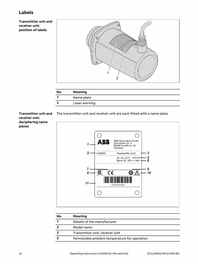
Labels
No. Meaning
1 Name plate
2 Laser warning
The transmitter unit and receiver unit are each fitted with a name plate.
No. Meaning
1 Details of the manufacturer
2 Model name
3 Transmitter unit, receiver unit
5 Permissible ambient temperature for operation
Transmitter unit and receiver unit: position of labels
Transmitter unit and receiver unit: deciphering name plates

OI/LS4000/NH3/H2O-EN Operating instruction LS4000 for NH3 and H2O 11
No. Meaning
6 Supply voltage and power consumption
7 CE mark
8 CSA marking
9 EFUP marking (EFUP = environment friendly use period): 50 years of operating time in accordance with the EU's RoHS Directive without any leaks of substances hazardous to health or the envi-ronment under normal conditions of use
10 Symbol: See operating instructions
11 Serial number, displayed as a bar code and in plain text
The transmitter unit and receiver unit are each fitted with a laser warning.
Meaning: Class I infrared laser beam invisible to the human eye.
No. Meaning
1 Details of the manufacturer
2 Model name
3 F-no. = Manufacturing number, A no. = Order no.
4 Supply voltage and power consumption
Transmitter unit and receiver unit: deciphering the laser warning
Junction box: interpreting the name plate

12 Operating instruction LS4000 for NH3 and H2O OI/LS4000/NH3/H2O-EN
No. Meaning
5 Sample component and measuring range
6 Symbol: See operating instructions
7 CSA marking
8 EFUP marking (EFUP = environment friendly use period): 50 years of operating time in accordance with the EU's RoHS Directive without any leaks of substances hazardous to health or the envi-ronment under normal conditions of use
9 CE mark

OI/LS4000/NH3/H2O-EN Operating instruction LS4000 for NH3 and H2O 13
Preparing for installation
Topic PagePreparing the system ........................................................................................... 13
Preparing the installation site ........................................................................... 14
Process purging ..................................................................................................... 16
Scope of delivery ................................................................................................... 17
Laying out tools and support materials ...........................................................18
Determining cable runs and line runs ................................................................ 19
Preparing the system
Perform the following steps in accordance with the system documentation:
Step Procedure
1 Shut down the system in which the laser analyzer is to be fitted.
2 Wait until the system temperature has fallen to its original level.
3 Ensure that the system is no longer pressurized.
4 Secure the system against startup.
Shutting down and securing the system
14 Operating instruction LS4000 for NH3 and H2O OI/LS4000/NH3/H2O-EN
Preparing the installation site
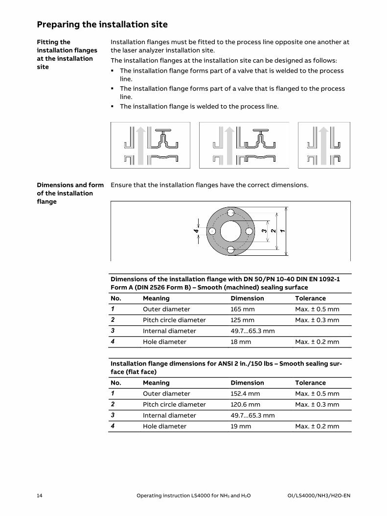
Installation flanges must be fitted to the process line opposite one another at the laser analyzer installation site.
The installation flanges at the installation site can be designed as follows:
The installation flange forms part of a valve that is welded to the process line.
The installation flange forms part of a valve that is flanged to the process line.
The installation flange is welded to the process line.
Ensure that the installation flanges have the correct dimensions.
Dimensions of the installation flange with DN 50/PN 10-40 DIN EN 1092-1 Form A (DIN 2526 Form B) – Smooth (machined) sealing surface
No. Meaning Dimension Tolerance
1 Outer diameter 165 mm Max. ± 0.5 mm
2 Pitch circle diameter 125 mm Max. ± 0.3 mm
3 Internal diameter 49.7...65.3 mm
4 Hole diameter 18 mm Max. ± 0.2 mm
Installation flange dimensions for ANSI 2 in./150 lbs – Smooth sealing sur-face (flat face)
No. Meaning Dimension Tolerance
1 Outer diameter 152.4 mm Max. ± 0.5 mm
2 Pitch circle diameter 120.6 mm Max. ± 0.3 mm
3 Internal diameter 49.7...65.3 mm
4 Hole diameter 19 mm Max. ± 0.2 mm
Fitting the installation flanges at the installation site
Dimensions and form of the installation flange
OI/LS4000/NH3/H2O-EN Operating instruction LS4000 for NH3 and H2O 15
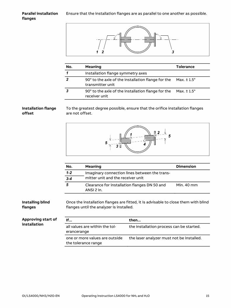
Ensure that the installation flanges are as parallel to one another as possible.
No. Meaning Tolerance
1 Installation flange symmetry axes
2 90° to the axle of the installation flange for the transmitter unit
Max. ± 1.5°
3 90° to the axle of the installation flange for the receiver unit
Max. ± 1.5°
To the greatest degree possible, ensure that the orifice installation flanges are not offset.
No. Meaning Dimension
1-2 Imaginary connection lines between the trans-mitter unit and the receiver unit
3-4
5 Clearance for installation flanges DN 50 and ANSI 2 in.
Min. 40 mm
Once the installation flanges are fitted, it is advisable to close them with blind flanges until the analyzer is installed.
If... then...
all values are within the tol-erancerange
the installation process can be started.
one or more values are outside the tolerance range
the laser analyzer must not be installed.
Parallel installation flanges
Installation flange offset
Installing blind flanges
Approving start of installation
16 Operating instruction LS4000 for NH3 and H2O OI/LS4000/NH3/H2O-EN
Process purging
Process purging is a continuous purging process used to protect the optical surfaces (lenses) against the build-up of dirt. This process also cools the transmitter and receiver units.
The purging medium is connected to the purging flange and flows into the process, where it mixes with the process gas.
Ensure that a purging flange is fitted for both the transmitter unit and the receiver unit.
Ensure that the purge air can be monitored. Failure of the purging process can result in irreversible damage to the lenses and cause the transmitter and receiver units to overheat.
The following are suitable for use as purging fluids, depending on the applica-tion (see data sheet):
Compressed air or Nitrogen Compressed air quality: dry and oil-free (in accordance with ISO 8573.1, Class 2-3)
Recommended pressure: typically around 25 % above the process pressure.
Recommended flow rate: 20–100 l/min.
If... then...
all requirements are met the receiver unit and the transmitter unit can be installed.
one or more of the requirements are not met
the receiver unit and the transmitter unit must not be installed.
To avoid damage to the parts of the gas analyzer affected by the process gas, process purging should be commissioned right after the gas analyzer is in-stalled.
Ensuring purging
Ensuring purge air monitoring
Checking purging medium requirements
Purging after installation

OI/LS4000/NH3/H2O-EN Operating instruction LS4000 for NH3 and H2O 17
Scope of supply and delivery
Unpack all parts included in the scope of delivery.
Ensure that all delivered parts match your order.
Quantity Designation
1 Transmitter unit with connection cable and protective cap for the lens
1 Receiver unit with connection cable and protective cap for the lens
1 Junction box, power supply unit fitted, cable glands pre-installed
1 Ethernet adapter
2 Purging flanges with seals and fastening clips (as per the order)
1 Analyzer data sheet (in the junction box)
1 Operating Instruction
1 DVD-ROM "Software tools and technical documentation"
Accessories included as per customer order
Keep the transport packaging of the transmitter unit and receiver unit for any possible required transport in the future. Keep the yellow protective caps of the lenses for service purposes. Dispose of the remaining packaging material in accordance with local regulations.
Finally, check that all parts are complete and in perfect condition.
If... then...
all parts are in perfect condition the installation process can be started.
one or more parts are missing or are not in perfect condition
the laser analyzer must not be installed.
Unpacking devices and accessories
Identifying devices and accessories
Keeping or disposing of packaging material
Final check

18 Operating instruction LS4000 for NH3 and H2O OI/LS4000/NH3/H2O-EN
Laying out tools and support materials
Lay out the following tools:
Quantity Tool Size
1 Spanner 13 mm
1 Spanner 16 mm
2 Spanner 24 mm
1 Slot screwdriver 3 mm or 4 mm
1 Slot screwdriver 6.5 mm
1 Phillips screwdriver Phillips No. 2
1 Allen key 5 mm
Lay out the following support materials:
Quantity Tools
1 Laser alignment tool (optional)
Laying out tools
Laying out support materials

OI/LS4000/NH3/H2O-EN Operating instruction LS4000 for NH3 and H2O 19
Determining cable runs and line runs
The cable runs must meet the following requirements:
No crossing of walkways No risk of mechanical stress No chemical or corrosive influences No extreme temperature effects Possibility of secure cable attachment
Lay out all cables and lines for connecting the devices.
Select the cable lengths and line lengths according to the conditions in the area.
For details of cable specifications, see Observing cable specifications (see page 38).
The cable clips and line brackets must meet the following conditions:
They must allow the cables and lines to be laid securely. It must be possible to open the cable clips and line brackets to allow the
cables and lines to be removed temporarily for calibration of a separate calibration set or for servicing.
Determining cable runs and line runs
Laying out cables and lines
Requirements for cable clips and line brackets

20 Operating instruction LS4000 for NH3 and H2O OI/LS4000/NH3/H2O-EN
Installing components
Topic PageOption: Installing the insertion tubes .............................................................. 20
Option: Installing the isolation flange .............................................................. 22
Installing the purging flanges ............................................................................ 26
Option: Installing the validation cell ................................................................. 33
Installing the transmitter unit and receiver unit ............................................ 35
Option: Installing the insertion tubes
Topic PageProviding an overview ......................................................................................... 20
Installing insertion tubes ..................................................................................... 21
Providing an overview
If... then...
the measuring section through the process does not allow for clear laser transmission (e.g. due to high dust load)
insertion tubes must be installed.
the measuring path through the process en-sures proper laser light transmission
no insertion tubes must be installed.
Insertion tubes cannot be installed in conjunction with isolation flanges.
No. Meaning
1 Transmitter unit
2 Purging flange
3 Insertion tube
4 Process
5 Insertion tube
6 Purging flange
7 Receiver unit
When must insertion tubes be installed?
Providing an overview
OI/LS4000/NH3/H2O-EN Operating instruction LS4000 for NH3 and H2O 21
Installing insertion tubes
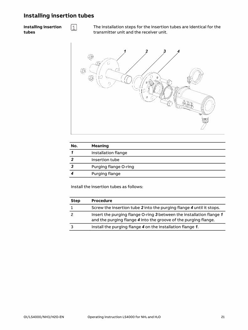
The installation steps for the insertion tubes are identical for the transmitter unit and the receiver unit.
No. Meaning
1 Installation flange
2 Insertion tube
3 Purging flange O-ring
4 Purging flange
Install the insertion tubes as follows:
Step Procedure
1 Screw the insertion tube 2 into the purging flange 4 until it stops.
2 Insert the purging flange O-ring 3 between the installation flange 1 and the purging flange 4 into the groove of the purging flange.
3 Install the purging flange 4 on the installation flange 1.
Installing insertion tubes
22 Operating instruction LS4000 for NH3 and H2O OI/LS4000/NH3/H2O-EN
Option: Installing the isolation flange
Topic PageProviding an overview ......................................................................................... 22
Follow the safety instructions ........................................................................... 23
Installing the isolation flange ............................................................................ 24
Providing an overview
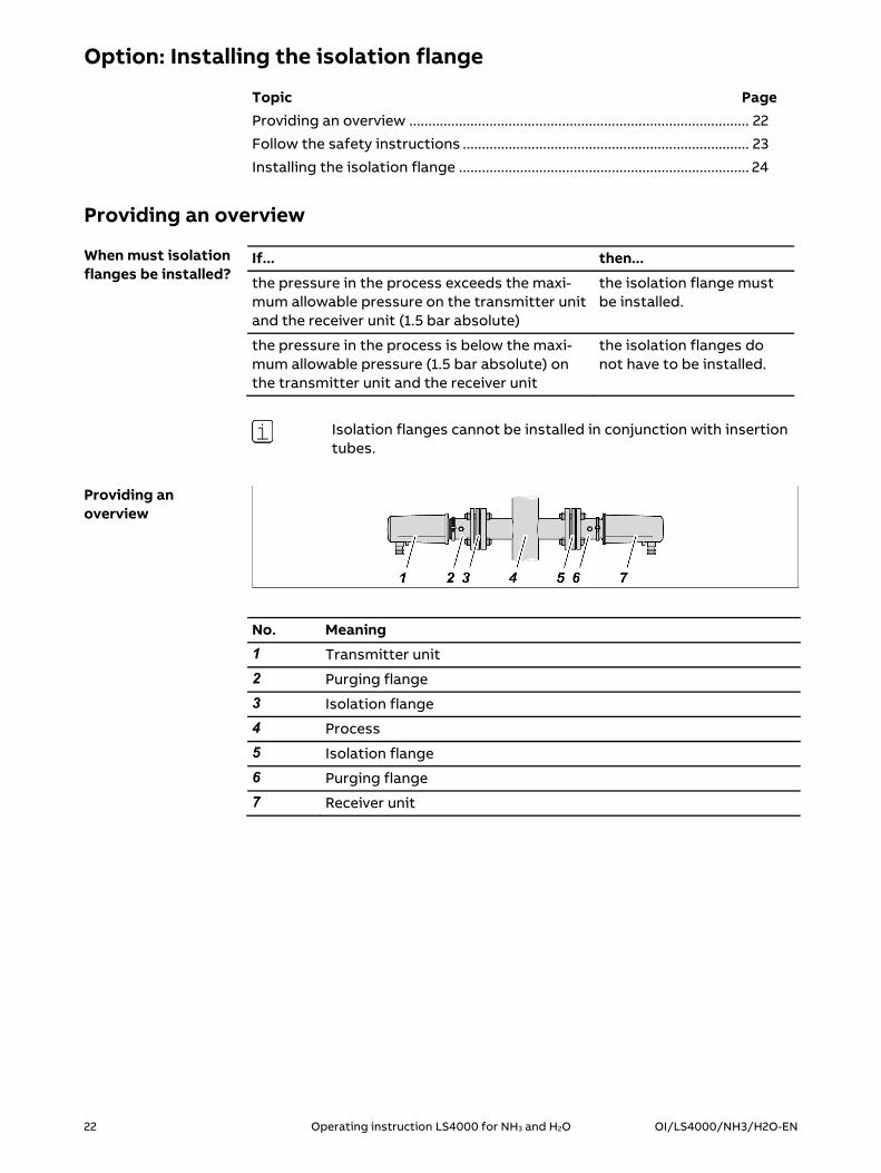
If... then...
the pressure in the process exceeds the maxi-mum allowable pressure on the transmitter unit and the receiver unit (1.5 bar absolute)
the isolation flange must be installed.
the pressure in the process is below the maxi-mum allowable pressure (1.5 bar absolute) on the transmitter unit and the receiver unit
the isolation flanges do not have to be installed.
Isolation flanges cannot be installed in conjunction with insertion tubes.
No. Meaning
1 Transmitter unit
2 Purging flange
3 Isolation flange
4 Process
5 Isolation flange
6 Purging flange
7 Receiver unit
When must isolation flanges be installed?
Providing an overview
OI/LS4000/NH3/H2O-EN Operating instruction LS4000 for NH3 and H2O 23
Follow the safety information
The isolation flange is tested for use as an accessory together with certified pressure equipment. It meets the requirements of the European Directive 2014/68/EC (Pressure Equipment Di-rective). Note the test report included with the isolation flange!
The isolation flange must not be exposed to any kind of shock! The isolation flange must not be dropped! The window must not be damaged! The flange surface on the process side must not be damaged! Scratches, in particular those in a radial direction, affect the seal integrity of the connection to the installation flange. The factory installed purge gas connection (Swagelok® connec-tion) must not be loosened or replaced! The fixing screws of the retaining ring for the window must not be loosened! The surface of the installation flange must be level and must not be damaged or deformed! Otherwise, the seal integrity of the connection with the isolation flange cannot be guaranteed!
The isolation flange must not be installed, If it has been exposed to any kind of shock If it has been dropped If it has been exposed to temperatures or pressures above
the permitted range If the window has scratches or cracks or chips If the flange surface on the process side is damaged If the isolation flange flat gasket is damaged If the surface of the installation flange is damaged! If the isolation flange is damaged, it must be sent to the manu-facturer for repair or reprocessing.
The user is responsible for making sure that the materials of the isolation flange and the isolation flange flat gasket are compati-ble with the process gas. Improper use may lead to corrosion or erosion of the material, and thus lead to weakening of the material. In particular, oxidation processes or high-temperature processes with high oxygen concentrations can impair the stability and thus the seal integrity of the isolation flange flat gasket. The isolation flange flat gasket is made of novaphit® SSTCTA-L, a material manufactured by Frenzelit Werke GmbH.
Safety instructions for handling an isolation flange

24 Operating instruction LS4000 for NH3 and H2O OI/LS4000/NH3/H2O-EN
Installing the isolation flange
The installation steps for the isolation flange are identical for the transmitter unit and the receiver unit.
No. Meaning
1 M16 fastening nuts with washers (4 pieces each)
2 Installation flange
3 Isolation flange flat gasket
4 Purge gas connection (1/4 inch Swagelok® connection)
5 Locking screws (4 pieces)
6 Threaded rods (4 pieces)
7 Isolation flange
8 Purging flange O-ring
9 Purging flange
10 M16 fastening nuts with washers (4 pieces each)
11 Purging flange flat gasket
Install the isolation flanges as follows:
Step Procedure
1 Before installing: Adjust the position of the threaded rods 6 screwed into the isolation flange to the thickness of the installa-tion flange and of the purging flange. If necessary, loosen the lock-ing screws that have been loosely screwed in to do so 5.
2 Insert the isolation flange flat gasket 3 between the installation flange 2 and the isolation flange 7.
Installing the isolation flange

OI/LS4000/NH3/H2O-EN Operating instruction LS4000 for NH3 and H2O 25
Step Procedure
3 Install the isolation flange 7 with the fastening nuts and washers 1 on the installation flange 2. The retaining ring for the window in the isolation flange must point towards the installation flange.
4 Insert the purging flange O-ring 8 between the isolation flange 7 and the purging flange 9.
5 Install the purging flange 9 with the fastening nuts and washers 10 on the isolation flange 7.
6 Tighten the four locking screws 5.
7 For the purge gas supply, connect a pipe with an 8 mm outside diameter to the purge gas connection 4 (1/4 inch Swagelok® con-nection).
Tighten all fastening nuts after assembly at intervals of 24, 48 and 72 hours, in order to compensate for the lingering tension release in the material of the isolation flange flat gasket.
Tightening fastening nuts

26 Operating instruction LS4000 for NH3 and H2O OI/LS4000/NH3/H2O-EN
Installing the purging flanges
Topic PageProviding an overview ......................................................................................... 26
Installing the purging flanges ............................................................................. 27
Roughly pre-aligning the purging flanges ....................................................... 28
Connecting the purging lines ............................................................................. 32
Providing an overview
No. Meaning
1 Receiver unit
2 Clamp
3 Purging flange
4 Installation flange
5 Transmitter unit
The purging flanges have a 1/4 inch Swagelok® connection for pipes with an 8 mm outside diameter.
Providing an overview

OI/LS4000/NH3/H2O-EN Operating instruction LS4000 for NH3 and H2O 27
Installing the purging flanges
The installation steps for the purging flanges are identical for the transmitter unit and the receiver unit.
No. Meaning
1 4x M 16 bolts
2 Installation flange
3 Purging flange O-ring
4 Purging flange
5 4x M 16 nuts
Install the purging flanges as follows:
Step Procedure
1 Insert the purging flange O-ring 3 into the groove of the installa-tion flange 2.
2 Place the purging flange 4 on the installation flange 2.
3 Screw in the flange loosely.
Fitting the purging flanges to the installation flanges

28 Operating instruction LS4000 for NH3 and H2O OI/LS4000/NH3/H2O-EN
Roughly pre-aligning the purging flanges
We recommend using the laser alignment tool (available as an accessory) for rough coaxial alignment of the opposite purging flanges. The laser alignment tool consists of a laser pointer and a focusing screen.
Fine alignment of the purging flange takes place once all the de-vices have been electrically connected using the instrument soft-ware.
The clamps for fastening the laser alignment tool must only be used to fasten the laser pointer and the focusing screen. It is prohibited to use these clamps for mounting the transmitter unit and the receiver unit. The clamps are labeled with a correspond-ing note.
The laser alignment tool falls into laser protection class 3A.
Step Procedure
1 Install the laser pointer on the purging flange to which the trans-mitter unit should be mounted, and the focusing screen on the purging flange to which the receiver unit should be mounted. Per-form the rough alignment.
2 Install the laser pointer on the purging flange to which the receiver unit should be mounted, and the focusing screen on the purging flange to which the transmitter unit should be mounted. Perform the rough alignment.
3 Install the laser pointer on the purging flange to which the trans-mitter unit should be mounted, and the focusing screen on the purging flange to which the receiver unit should be mounted. Per-form the rough alignment.
Using the alignment tool
Rough alignment: Three-step procedure
Installing the laser pointer

OI/LS4000/NH3/H2O-EN Operating instruction LS4000 for NH3 and H2O 29
No. Meaning
1 Laser pointer
2 Purging flange flat gasket
3 Clamp
4 Purging flange
Install the laser pointer as follows:
Step Procedure
1 Place the purging flange flat gasket 2 into the groove of the purg-ing flange 4.
2 Place the laser pointer 1 on the purging flange 4.
3 Fasten the laser pointer 1 using the clamp 3.
No. Meaning
1 Focusing screen
2 Purging flange flat gasket
3 Clamp
4 Purging flange
Install the focusing screen as follows:
Step Procedure
1 Place the purging flange flat gasket 2 into the groove of the purg-ing flange 4.
2 Place the focusing screen 1 onto the purging flange 4.
3 Fasten the focusing screen 1 using the clamp 3.
Installing the focusing screen

30 Operating instruction LS4000 for NH3 and H2O OI/LS4000/NH3/H2O-EN
During pre-alignment, the purging flanges installed opposite to one another are aligned coaxially to one another using the laser alignment aid.
No. Meaning
1 Laser pointer on/off switch
2 Laser beam
3 Focusing screen
No. Meaning
1 4 stud screws
2 4 fastening nuts
Principle of rough pre-alignment
Roughly pre-aligning the purging flanges

OI/LS4000/NH3/H2O-EN Operating instruction LS4000 for NH3 and H2O 31
Align the purging flanges as follows:
Step Procedure
1 Unscrew the 4 stud screws 1 until the ends of the screws no longer protrude from the holes.
2 Switch on the laser pointer.
3 Align the purging flanges by adjusting the 4 fastening nuts 2, until the laser beam hits the center of the focusing screen.
4 Turn the 4 stud screws 1 until they reach a stop, so that they fix the setting.
5 Switch off the laser pointer.
6 Disassemble the laser pointer and the focusing screen.
The clamps for fastening the laser alignment tool must not be used for mounting the transmitter unit or receiver unit.

32 Operating instruction LS4000 for NH3 and H2O OI/LS4000/NH3/H2O-EN
Connecting the purging lines
Connect the purging lines as follows:
Step Procedure
1 For the purge gas supply to both purging flanges, connect a pipe with an 8 mm outside diameter to each purge gas connection (1/4 inch Swagelok® connection).

OI/LS4000/NH3/H2O-EN Operating instruction LS4000 for NH3 and H2O 33
Option: Installing the validation cell
Topic PageProviding an overview ......................................................................................... 33
Installing the validation cell ................................................................................ 34
Providing an overview
If... then...
validations must be performed on the process due to the appli-cation
a validation cell must be installed. This is included in the scope of delivery, depend-ing on the application.
no validation cell is installed validations can only be performed inde-pendently of the process on the separate calibration set.
No. Meaning
1 Transmitter unit
2 Validation cell
3 Test gas supply and discharge
4 Purging flange
5 Process
6 Purging flange
7 Receiver unit
The validation cell has two 1/4 inch Swagelok® connection for pipes with an 8 mm outside diameter.
The validation cell is to be installed on the side of the transmitter unit.
Under what circumstances is a validation cell required?
Providing an overview

34 Operating instruction LS4000 for NH3 and H2O OI/LS4000/NH3/H2O-EN
Installing the validation cell
No. Meaning
1 Purging flange
2 Purging flange flat gasket
3 Clamp
4 Validation cell
Install the validation cell as follows:
Step Procedure
1 Place the purging flange flat gasket 2 into the groove of the purg-ing flange 1.
2 Set the validation cell 4 on the purging flange 1 on the side of the transmitter unit.
3 Fasten the validation cell 4 using the clamp 3.
4 For the test gas supply and discharge, connect a pipe with an 8 mm outside diameter to each 1/4 inch Swagelok® connection.
5 Install the transmitter unit.
Installing the validation cell

OI/LS4000/NH3/H2O-EN Operating instruction LS4000 for NH3 and H2O 35
Installing the transmitter unit and receiver unit
Topic PageProviding an overview ......................................................................................... 35
Installing the transmitter unit and receiver unit ............................................ 36
Providing an overview
No. Meaning
1 Receiver unit
2 Clamp
3 Purging flange
4 Installation flange
5 Transmitter unit
Providing an overview

36 Operating instruction LS4000 for NH3 and H2O OI/LS4000/NH3/H2O-EN
Installing the transmitter unit and receiver unit
The self-locking nuts of the clamps for mounting the transmitter unit and the receiver unit may only be used once. The clamps intended for fastening the laser alignment tool must not be used to install the transmitter unit or the receiver unit.
The transmitter unit and receiver unit are installed using exactly the same steps.
No. Meaning
1 Purging flange flat gasket
2 Clamp
3 Transmitter unit or receiver unit
Install the transmitter unit and receiver unit as follows:
Step Procedure
1 If necessary, replace the self-locking nuts for the clamps with new self-locking nuts.
2 Insert the purging flange flat gasket 1 into the groove of the purg-ing flange.
3 Place the transmitter unit or the receiver unit onto the purging flange.
4 Attach the transmitter unit or the receiver unit using the clamp 2.
To avoid damage to the parts of the gas analyzer affected by the process gas, process purging should be commissioned right after the gas analyzer is in-stalled.
Installing the transmitter unit and receiver unit
Purging after installation
OI/LS4000/NH3/H2O-EN Operating instruction LS4000 for NH3 and H2O 37
Connecting the electrical leads
Topic PageProviding an overview ......................................................................................... 37
Observing cable specifications ......................................................................... 38
Protecting the line voltage supply .................................................................... 39
Installing the junction box .................................................................................. 40
Fitting the cable clips and line brackets .......................................................... 41
Selecting a suitable cable gland ........................................................................ 42
Leading cables through cable glands ............................................................... 43
Establishing a protective grounding ................................................................ 44
Connecting the transmitter unit to the junction box .................................... 45
Connecting the receiver unit to the junction box .......................................... 46
Option: connecting the T/P probes to the junction box .............................. 47
Connecting the analog and digital outputs to the junction box ................ 48
Connecting potential equalization ................................................................... 49
Connecting the power supply ............................................................................ 50
Providing an overview
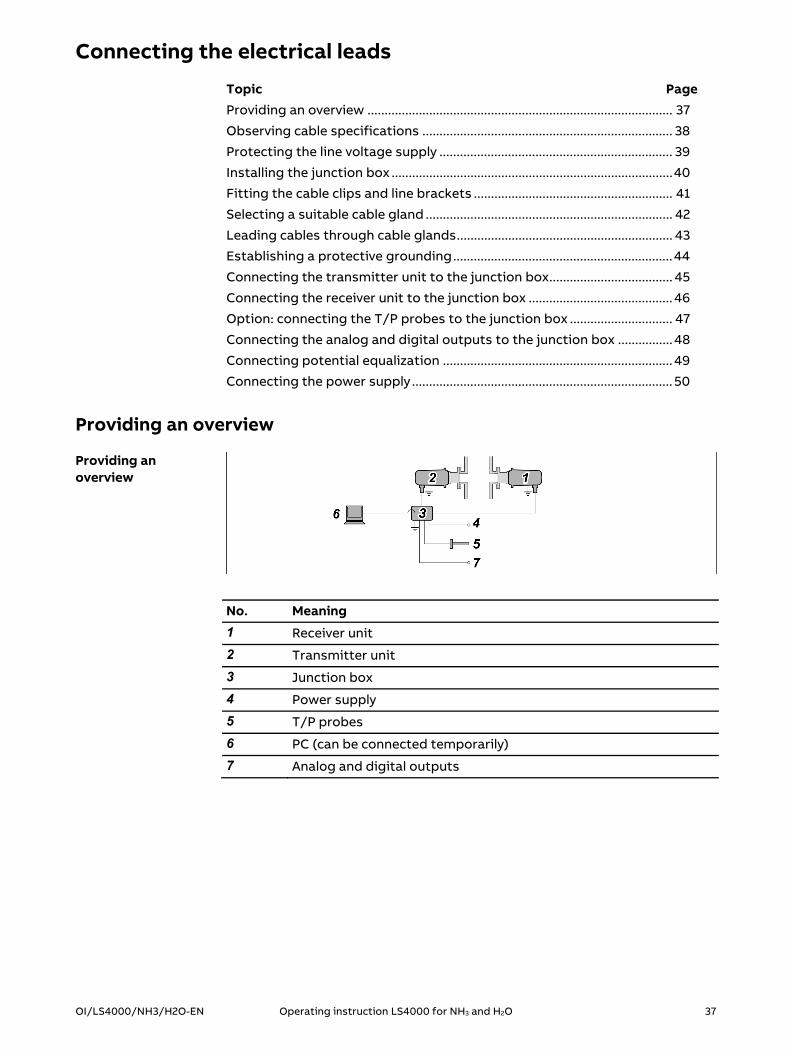
No. Meaning
1 Receiver unit
2 Transmitter unit
3 Junction box
4 Power supply
5 T/P probes
6 PC (can be connected temporarily)
7 Analog and digital outputs
Providing an overview
38 Operating instruction LS4000 for NH3 and H2O OI/LS4000/NH3/H2O-EN
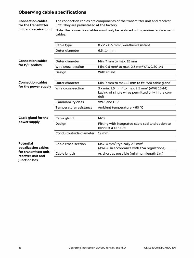
Observing cable specifications
The connection cables are components of the transmitter unit and receiver unit. They are preinstalled at the factory.
Note: the connection cables must only be replaced with genuine replacement cables.
Cable type 8 x 2 x 0.5 mm2; weather-resistant
Outer diameter 6.5...14 mm
Outer diameter Min. 7 mm to max. 12 mm
Wire cross-section Min. 0.5 mm2 to max. 2.5 mm2 (AWG 20-14)
Design With shield
Outer diameter Min. 7 mm to max.12 mm to fit M20 cable gland
Wire cross-section 3 x min. 1.5 mm2 to max. 2.5 mm2 (AWG 16-14) Laying of single wires permitted only in the con-duit
Flammability class VW-1 and FT-1
Temperature resistance Ambient temperature > 60 °C
Cable gland M20
Design Fitting with integrated cable seal and option to connect a conduit
Conduitoutside diameter 19 mm
Cable cross-section Max. 4 mm2; typically 2.5 mm2 (AWG 8 in accordance with CSA regulations)
Cable length As short as possible (minimum length 1 m)
Connection cables for the transmitter unit and receiver unit
Connection cables for P/T probes
Connection cables for the power supply
Cable gland for the power supply
Potential equalization cables for transmitter unit, receiver unit and junction box

OI/LS4000/NH3/H2O-EN Operating instruction LS4000 for NH3 and H2O 39
Protecting the line voltage supply
To protect the line voltage supply, proceed as follows:
The feeder must be protected using an external overcurrent protection device.
It must be possible to switch off the feeder using a separator (external switch).
The separator must be located near the supplied device. The way in which the supplied device is arranged must not compromise
the operation of the separator. The separator must be identified so that the assignment to the supplied
device is clearly visible.
Requirements for protecting the line voltage supply
40 Operating instruction LS4000 for NH3 and H2O OI/LS4000/NH3/H2O-EN
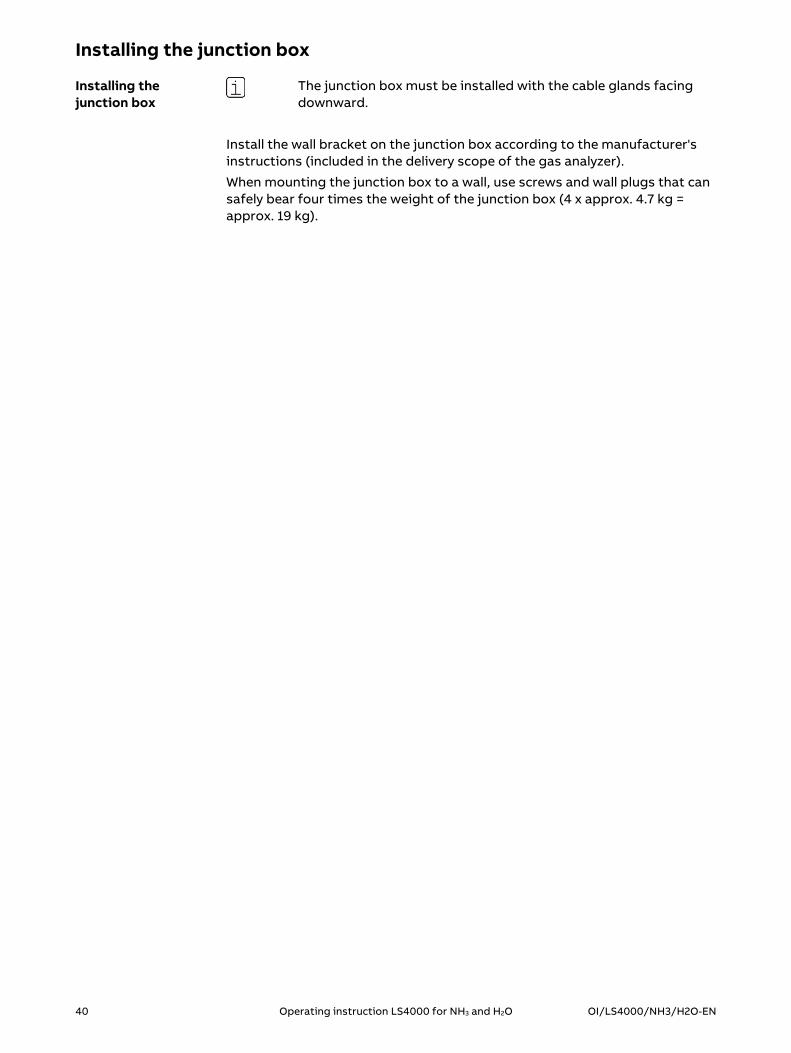
Installing the junction box
The junction box must be installed with the cable glands facing downward.
Install the wall bracket on the junction box according to the manufacturer's instructions (included in the delivery scope of the gas analyzer).
When mounting the junction box to a wall, use screws and wall plugs that can safely bear four times the weight of the junction box (4 x approx. 4.7 kg = approx. 19 kg).
Installing the junction box

OI/LS4000/NH3/H2O-EN Operating instruction LS4000 for NH3 and H2O 41
Fitting the cable clips and line brackets
The cable clips and line brackets must meet the following conditions:
They must allow the cables and lines to be laid securely. It must be possible to open the cable clips and line brackets to allow the
cables and lines to be removed temporarily for calibration of a separate calibration set or for servicing.
Fit the cable clips and line brackets along the defined cable and line runs.
Requirements for cable clips and line brackets
Fitting the cable clips and line brackets

42 Operating instruction LS4000 for NH3 and H2O OI/LS4000/NH3/H2O-EN
Selecting a suitable cable gland
Select a suitable cable gland for each cable.
The following always applies:
Shielded cables must only be routed through metal cable glands. The cable diameter must fit the diameter of the cable gland.
No. Cable Cable gland Cable diameter
1 Power supply M20 8…15 mm
2 P/T probes M20 7…13 mm
3 Analog and digital outputs M20 7…13 mm
4 Receiver unit M25 9…17 mm
5 Transmitter unit M25 9…17 mm
Selecting a suitable cable gland

OI/LS4000/NH3/H2O-EN Operating instruction LS4000 for NH3 and H2O 43
Leading cables through cable glands
No. Meaning
1 Union nut
2 Connection socket
3 Braided shield
4 Springs
Proceed as follows:
Step Procedure
1 Feed the cable through the union nut and through the connection socket into the junction box until the springs come into contact with the bare or exposed braided shield.
2 Screw the union nut onto the connection socket. Tightening torque: M20 power supply: 10 Nm M20 P/T probes and analog/digital outputs: 12 Nm M25 Transmitter/receiver unit connection cable: 12 Nm
3 Close the junction box.
Metal cable glands

44 Operating instruction LS4000 for NH3 and H2O OI/LS4000/NH3/H2O-EN
Establishing a protective grounding
The protective grounding is established via the PE conductor of the power cable.
Proceed as follows:
Step Procedure
1 Connect the PE conductor of the power cable to the PE terminal of the terminal strip.
Establishing a protective grounding

OI/LS4000/NH3/H2O-EN Operating instruction LS4000 for NH3 and H2O 45
Connecting the transmitter unit to the junction box
Connect the transmitter unit to the junction box.
The wires in the connection cable are color coded to facilitate the assignment to the terminals.
Connections to the terminal strip are made as follows:
Terminal Cable wire color Function
1 White +24 V
3 Brown GND
5 Green TURU_A
6 Yellow TURU_B
7 Gray AUX_A
8 Pink AUX_B
12 Blue AO1 (4...20 mA)
13 Red AO2 (4...20 mA)
20 Black INTERNAL
21 Violet INTERNAL
22 Gray/pink INTERNAL
- Blue/red 1) (not assigned)
23 White/green ETH_TX+
24 Brown/green ETH_TX-
25 White/yellow ETH_RX+
26 Brown/yellow ETH_RX-
1) This wire is not used and must be secured in the junction box. If a power supply is installed in the junction box, the wire that is not used can be connected to a free PE terminal. Otherwise, the wire must be insulated with shrinkdown plastic tubing and fixed to the cable harness with cable ties.
Connecting the transmitter unit

46 Operating instruction LS4000 for NH3 and H2O OI/LS4000/NH3/H2O-EN
Connecting the receiver unit to the junction box
Connect the receiver unit to the junction box.
The wires in the connection cable are color coded to facilitate the assignment to the terminals.
Connections to the terminal strip are made as follows:
Terminal Cable wire color Function
2 White +24 V
4 Brown GND
5 Green TURU_A
6 Yellow TURU_B
9 Gray AUXIF_A
10 Pink AUXIF_B
11 Red AUX_IO
14 Blue AO3 (4...20 mA)
16 Black DO1_A
17 Violet DO1_B
18 Gray/pink DO2_A
19 Blue/red DO2_B
27 White/green T-Probe_in
28 Brown/green T-Probe_out
29 White/yellow P-Probe_in
30 Brown/yellow P-Probe_out
Connecting the receiver unit

OI/LS4000/NH3/H2O-EN Operating instruction LS4000 for NH3 and H2O 47
Option: connecting the T/P probes to the junction box
The T/P probes for dynamic temperature and pressure correction are not included in the delivery scope.
The T/P probes require a separate power supply and must provide a 4…20-mA output signal.
Connect the T/P probes to the junction box.
Connections to the terminal strip are made as follows:
Terminal Signal Function
27 T probe in (+) 4…20-mA input
28 T probe out (-) Analog input for dynamic temperature correction
29 P probe in (+) 4…20-mA input
30 P probe out (-) Analog input for dynamic pressure correction
Connecting T/P probes

48 Operating instruction LS4000 for NH3 and H2O OI/LS4000/NH3/H2O-EN
Connecting the analog and digital outputs to the junction box
Connect the analog and digital outputs to the junction box.
Connections to the terminal strip are made as follows:
Terminal Signal Function
12 AO1 (4...20mA) Analog output 1
13 AO2 (4...20mA) Analog output 2
14 AO3 (4...20mA) Analog output 3
15 GND Analog outputs GND
16 DO1_A Digital output 1
17 DO1_B
18 DO2_A Digital output 2
19 DO2_B
The assignment of the analog and digital outputs is determined during the installation and configuration of the gas analyzer.
Connecting analog and digital outputs
Layout of the analog and digital outputs
OI/LS4000/NH3/H2O-EN Operating instruction LS4000 for NH3 and H2O 49
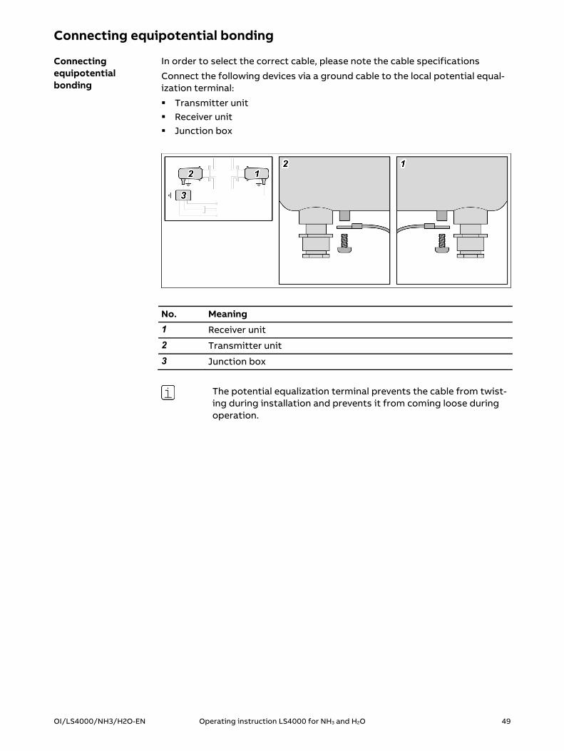
Connecting equipotential bonding
In order to select the correct cable, please note the cable specifications
Connect the following devices via a ground cable to the local potential equal-ization terminal:
Transmitter unit Receiver unit Junction box
No. Meaning
1 Receiver unit
2 Transmitter unit
3 Junction box
The potential equalization terminal prevents the cable from twist-ing during installation and prevents it from coming loose during operation.
Connecting equipotential bonding

50 Operating instruction LS4000 for NH3 and H2O OI/LS4000/NH3/H2O-EN
Connecting the power supply
This section only describes how to wire the power supply.
The device immediately starts up when the supply voltage is ap-plied, but it is not possible to recognize when this has happened. For this reason, the supply voltage must not yet be applied!
Note the cable specification!
Infrared laser beam invisible to the human eye. Risk of eye injury in the event of accidental startup. Keep device disconnected until final inspection.
Connections to the power supply unit are made as follows:
Terminal Cable wire color Position Function
PE Green/yellow PE terminal strip Protective earth
L Brown Power supply 100...240 V AC (phase)
N Blue Power supply 100...240 V AC (neutral)
Tightening torque of the screw terminals: 0.5 to 0.6 Nm
On the secondary side, the connection between the power supply unit and the terminal strip is already wired at the factory.
As shown in the figure, within the junction box, the primary lines and the secondary lines must be laid at a distance and secured in such a way that contact between them is excluded.
Connecting the 100-240 V AC power supply
Laying lines safely
OI/LS4000/NH3/H2O-EN Operating instruction LS4000 for NH3 and H2O 51
Gas analyzer start-up
Topic PageTesting and approving gas analyzer .................................................................. 51
Connecting the supply voltage .......................................................................... 53
Recognizing the operating condition ............................................................... 54
Connecting the PC to the junction box ............................................................ 55
Connecting to the instrument software .......................................................... 56
Menu structure of the instrument software ................................................... 57
Main menu ............................................................................................................. 58
System time menu (“System time”) .................................................................. 59
Fine alignment of the purging flanges ............................................................. 60
Fine alignment menu (“Alignment”) ................................................................. 62
Installation procedure menu ("Installation procedure") ............................... 63
Installation menu - Cable length menu ("Cable length") ............................... 64
Installation menu - Process parameters menu ("Process parameters") ... 65
Installation menu - Installation flanges menu ("Installation flanges") ....... 67
Installation menu - Ambient conditions menu ("Ambient conditions") .... 69
Installation menu - Measuring channels menu ("Channels")........................ 70
Installation menu - Analog and digital outputs menu ("Analog and digital outputs") ................................................................................................................. 72
Installation menu - Save settings menu ("Save settings") ........................... 74
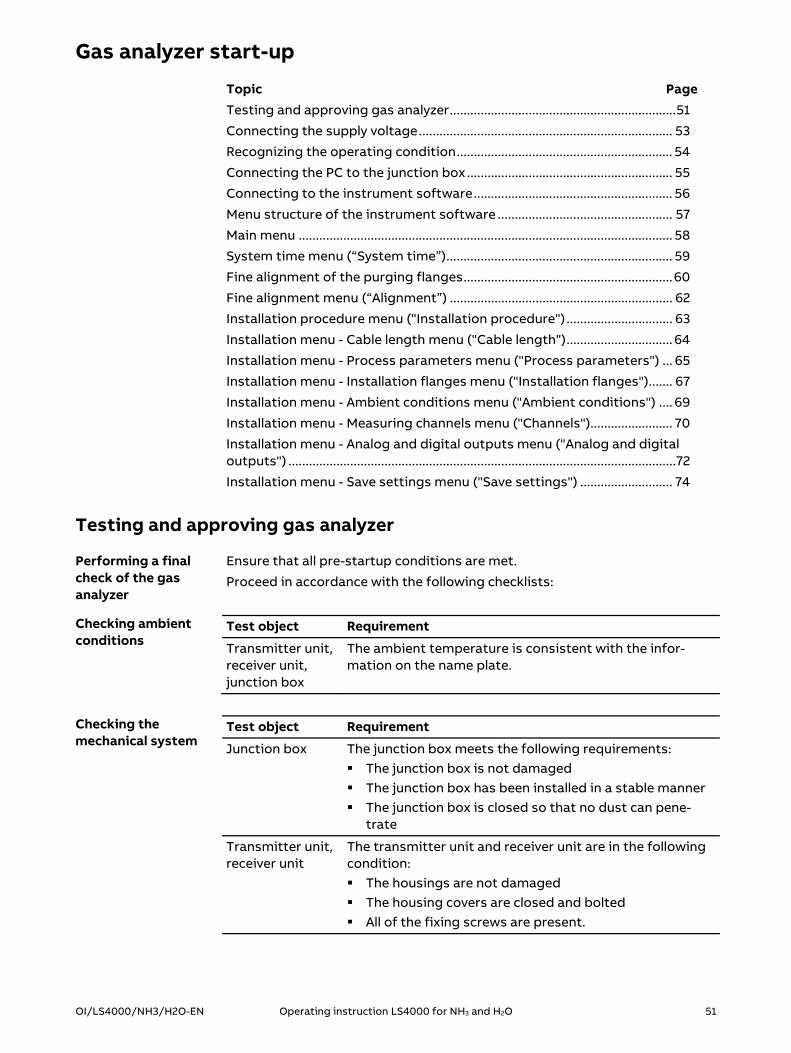
Testing and approving gas analyzer
Ensure that all pre-startup conditions are met.
Proceed in accordance with the following checklists:
Test object Requirement
Transmitter unit, receiver unit, junction box
The ambient temperature is consistent with the infor-mation on the name plate.
Test object Requirement
Junction box The junction box meets the following requirements: The junction box is not damaged The junction box has been installed in a stable manner The junction box is closed so that no dust can pene-
trate
Transmitter unit, receiver unit
The transmitter unit and receiver unit are in the following condition: The housings are not damaged The housing covers are closed and bolted All of the fixing screws are present.
Performing a final check of the gas analyzer
Checking ambient conditions
Checking the mechanical system

52 Operating instruction LS4000 for NH3 and H2O OI/LS4000/NH3/H2O-EN
Test object Requirement
The transmitter unit and receiver unit are installed so that the following requirements are met: The housings do not come into contact with any over-
pressure in the process gas path The housings are not improperly heated by the heat
generated at the contact point of the process gas path (purging flange).
Test object Requirement
Cable condition All cables are undamaged.
Cable types All connections are made using the specified cable type.
Shielded cables The shielded cables meet the following requirements: The cables are fed through metal cable glands The braided shield is properly connected to the cable
gland
Supply voltage The supply voltage is consistent with the information on the name plate of the junction box.
Connecting cables
All connecting cables meet the following requirements: The cables are properly installed and secured The cables in the junction box are connected using the
correct pin assignment The cables in the cable glands are sealed so that no
dust can penetrate All of the unused cable wire ends are insulated or
grounded
Cable glands The cables in the cable glands on the transmitter unit and receiver unit are fitted in a fixed position and can-not move.
Potential equali-zation terminal
The following devices are connected via a ground cable to the local potential equalization terminal: Transmitter unit Receiver unit Junction Box
If... then...
all the checks have been com-pleted with positive results
the analyzer may be put into use.
at least one check gave a nega-tive result
the analyzer may not be put into use.
the fault must be rectified.
the check must be repeated.
Checking the electrical system
Approving the analyzer for startup

OI/LS4000/NH3/H2O-EN Operating instruction LS4000 for NH3 and H2O 53
Connecting the supply voltage
Connect the supply voltage.
Connecting the supply voltage

54 Operating instruction LS4000 for NH3 and H2O OI/LS4000/NH3/H2O-EN
Recognizing the operating status
The Starting-up operating condition applies as soon as the analyzer is switched on.
Phase Action
1 The analyzer is switched on.
2 The analyzer loads the basic configuration.
3 The analyzer performs a self-test.
4 The analyzer is ready for initialization.
The Initializing operating condition applies as soon as starting-up is com-plete.
Phase Action
1 The analyzer checks the settings.
2 The analyzer checks that it is ready for operation.
If... then...
the settings are correct and the analyzer is ready for use
the analyzer switches to "Measuring" sta-tus.
at least one of the settings is not correct or the analyzer is not ready for use
the analyzer issues an error message.
the analyzer switches to the "Malfunction" operating status.
The Measuring operating condition applies as soon as initialization is com-pleted successfully. The "Measuring" operating status is the regular operating status during continuous operation.
The Malfunction operating condition applies when an error has occurred (also see Error messages in the Malfunction operating condition, see page 110).
Phase Action
1 An error occurs.
2 The digital output 1 sends an error signal to the system.
3 The analyzer ends the measuring process.
The Service operating condition can be started manually by the operator.
In the "Service" operating status, you can perform actions such as the follow-ing:
View the spectrum Performing calibration Enable the measurements log
Operating condition: "Starting-up"
Operating condition: "Initializing"
Operating condition: "Measuring"
Operating condition: "Malfunction"
Operating condition: "Service"

OI/LS4000/NH3/H2O-EN Operating instruction LS4000 for NH3 and H2O 55
Connecting the PC to the junction box
An RJ45 adapter board is provided for connecting the analyzer to a PC.
Proceed as follows:
Step Procedure
1 Open the junction box.
2 Connect the RJ45 adapter board to terminals 23–26 in the junction box.
3 Connect the PC to the RJ45 adapter board using a patch cable.
Connections to the terminal strip are made as follows:
Terminal Signal Function
23 ETH TX+ Ethernet TX+
24 ETH TX- Ethernet TX-
25 ETH RX+ Ethernet RX+
26 ETH RX- Ethernet RX-
Connecting the PC

56 Operating instruction LS4000 for NH3 and H2O OI/LS4000/NH3/H2O-EN
Connecting to the instrument software
The instrument software is an integral component of the transmitter unit and the receiver unit. It is accessed via a web browser.
The Web browsers Mozilla® Firefox® and Google ChromeTM are approved for use with the device software.
Note: Mozilla and Firefox are registered trademarks of the Mozilla Foundation. Chrome is a trademark of Google Inc.
Proceed as follows:
Step Procedure
1 Ensure that transmitter unit and receiver unit are connected to the junction box and ready for operation.
2 Ensure that a PC is connected to the junction box.
To start the instrument software, you need the IP address of the analyzer.
The factory-set IP address is provided in the analyzer data sheet.
Proceed as follows:
Step Procedure
1 Start up the PC.
2 Start up the web browser on your computer.
3 In your web browser, type the IP address of the analyzer.
The user interface of the instrument software is displayed:
Instrument software in the web browser
Connecting the devices
Starting the instrument software

OI/LS4000/NH3/H2O-EN Operating instruction LS4000 for NH3 and H2O 57
Menu structure of the instrument software
Main menu
System information
Instrument status
System time
Installation
Cable length
Process parameters
Installation flanges
Ambient conditions
Channels
Analog and digital outputs
Save settings
I/O verification
Alignment
Diagnostics
Service
Network settings
Spectrum
Calibration
Instrument logging
All menu illustrations in these operating instructions are examples. The actual menu display in the web browser may vary.

58 Operating instruction LS4000 for NH3 and H2O OI/LS4000/NH3/H2O-EN
Main menu
Enter password and log in as an operator.
Open menus
Name Meaning/function Password entry
Log in Enter the password and login The operator password is "xs2ls".
Log out Log out and return to the main menu without password entry
System information Call up the System information menu (see page 82)
without / after
Instrument status Call up the Instrument status menu (see page 83)
without / after
System time Call up the System time menu (see page 59)
without / after
Installation Call up the Installation menu (see page 63)
after
I/O Verification Call up the I/O verification menu (see page 84)
after
Alignment Call up the Alignment menu (see page 62)
after
Diagnostics Call up the Diagnostics menu (see page 85)
after
Service Call up the Service menu (see page 86)
after
The numbers which are displayed on the left next to the log in entry field are the serial number of the transmitter unit and the manufacturing no. (F-no) of the gas analyzer.
Intended use
Description

OI/LS4000/NH3/H2O-EN Operating instruction LS4000 for NH3 and H2O 59
System time menu
Set system time
Name Meaning/function
Log out Log out and return to the main menu
Current time View the current system time
Year Enter the year of the current date
Month Enter the month of the current date
Day Enter the day of the current date
Hour Enter the hour of the current time
Minute Enter the minutes of the current time
Second Enter the seconds of the current time
Set Activate your entries
Done Exit menu
We recommend that you perform a restart of the gas analyzer after changing system time settings. To do so, switch off the gas analyzer and power it back up again. Afterwards, check in the System time menu that the changed sys-tem time settings have been accepted.
Intended use
Description
Restart the gas analyzer

60 Operating instruction LS4000 for NH3 and H2O OI/LS4000/NH3/H2O-EN
Fine alignment of the purging flanges
Proceed as follows:
Step Procedure
1 Log on as an operator. The operator password is "xs2ls". The Main menu is displayed.
2 Call up the Alignment menu (see page 62). The "Alignment" menu appears. The current values "Relative transmission" and "Absolute transmis-sion" appear.
3 Click on "Align". The analyzer is now ready for fine alignment.
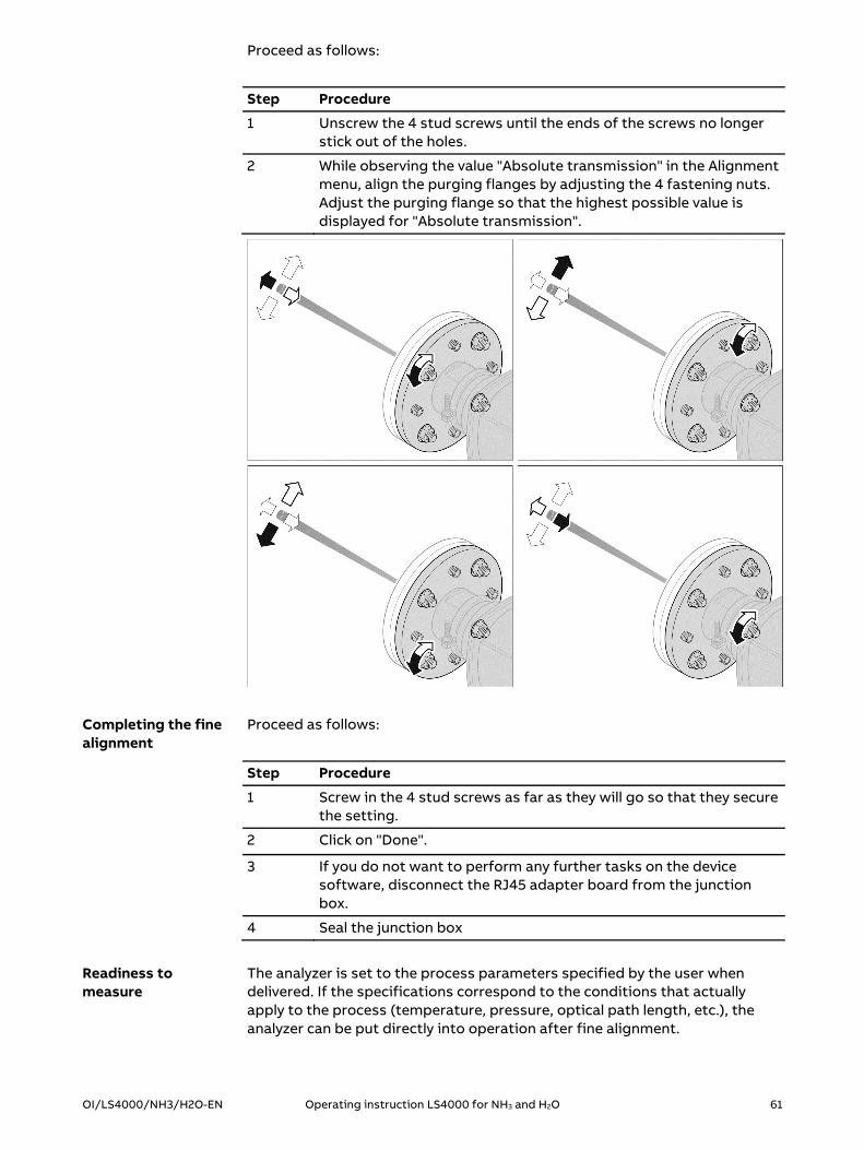
No. Meaning
1 4 stud screws
2 4 fastening nuts
Call up the Alignment menu
Fine alignment of the purging flanges
OI/LS4000/NH3/H2O-EN Operating instruction LS4000 for NH3 and H2O 61
Proceed as follows:
Step Procedure
1 Unscrew the 4 stud screws until the ends of the screws no longer stick out of the holes.
2 While observing the value "Absolute transmission" in the Alignment menu, align the purging flanges by adjusting the 4 fastening nuts. Adjust the purging flange so that the highest possible value is displayed for "Absolute transmission".
Proceed as follows:
Step Procedure
1 Screw in the 4 stud screws as far as they will go so that they secure the setting.
2 Click on "Done".
3 If you do not want to perform any further tasks on the device software, disconnect the RJ45 adapter board from the junction box.
4 Seal the junction box
The analyzer is set to the process parameters specified by the user when delivered. If the specifications correspond to the conditions that actually apply to the process (temperature, pressure, optical path length, etc.), the analyzer can be put directly into operation after fine alignment.
Completing the fine alignment
Readiness to measure

62 Operating instruction LS4000 for NH3 and H2O OI/LS4000/NH3/H2O-EN
Alignment menu
Perform fine alignment of the transmitter and receiver unit purging flanges
Name Meaning/function
Log out Log out and return to the main menu
Instrument mode Operating condition of the analyzer
Relative transmission Measured relative transmission
Absolute transmission Measured absolute transmission
Align Start fine alignment of the purging flange (see page 60)
Done Exit menu
Intended use
Description

OI/LS4000/NH3/H2O-EN Operating instruction LS4000 for NH3 and H2O 63
Installation procedure menu
Call up the configuration assistant
Start the 7-step configuration routine
Name Meaning/function
Log out Log out and return to the main menu
Cancel Exit menu
Next Start configuration routine
Step Procedure
1 Enter the length of the connection cable (see page 64).
2 Enter physical properties for the process (see page 65).
3 Enter physical properties for the flanges (see page 67).
4 Enter physical properties for the measuring environment (see page 69).
5 Configure measuring channels (see page 70).
6 Configure analog and digital outputs (see page 72).
7 Check settings and save or reject (see page 74). End configuration routine.
Intended use
Description
Configuration routine

64 Operating instruction LS4000 for NH3 and H2O OI/LS4000/NH3/H2O-EN
Installation - Cable length menu
Enter the length of the connection cables
Name Meaning/function
Log out Log out and return to the main menu
Cable length Enter the total length of the connection cables of the transmitter and receiver unit The length of the connection cables is provided in the analyzer data sheet.
Prev Back to previous menu
Cancel Cancel the process and exit the menu
Next Continue to the next menu
Intended use
Description

OI/LS4000/NH3/H2O-EN Operating instruction LS4000 for NH3 and H2O 65
Installation - Process parameters menu
Enter physical properties for the process
Name Meaning/function
Log out Log out and return to the main menu
Process path length Enter the length of the measuring section through the process between the flanges
When using insertion pipes: enter the free path length between the insertion pipes
Pressure input Select the source of the value for the pressure FIXED: Use a manually entered process value EXTERNAL: Use the value measured using a connected P-probe AMBIENT: Use the ambient value measured by the analyzer
Intended use
Description

66 Operating instruction LS4000 for NH3 and H2O OI/LS4000/NH3/H2O-EN
Name Meaning/function
Temperature input Select the source of the value for the temperature FIXED: Use a manually entered value EXTERNAL: Use the value measured using a connected T-probe AMBIENT: Use the ambient value measured by the analyzer
Fixed pressure level Enter a fixed value for the pressure
Fixed temperature level Enter a fixed value for the temperature
Offset pressure Enter the difference between the measured and actual pressure in the process
Offset temperature Enter the difference between the measured and actual temperature in the process
External pressure source Select interface to connect the P-probe CURRENT LOOP: 4 - 20 mA input
Pressure corresponding to 4 mA
Enter the pressure value that corresponds to a current of 4 mA
Pressure corresponding to 20 mA
Enter the pressure value that corresponds to a current of 20 mA
External temperature source
Select interface to connect the T-probe CURRENT LOOP: 4 - 20 mA input
Temperature corresponding to 4 mA
Enter the temperature value that corresponds to a current of 4 mA
Temperature corresponding to 20 mA
Enter the temperature value that corresponds to a current of 20 mA
Enable process broadening YES: Measurement with correction of the cross-sensitivity matrix (for in-process measurement) NO: NH3measurement without cross-sensitivity cor-rection (for calibration and validation)
Prev Back to previous menu
Cancel Cancel the process and exit the menu
Next Continue to the next menu
OI/LS4000/NH3/H2O-EN Operating instruction LS4000 for NH3 and H2O 67
Installation - Installation flanges menu
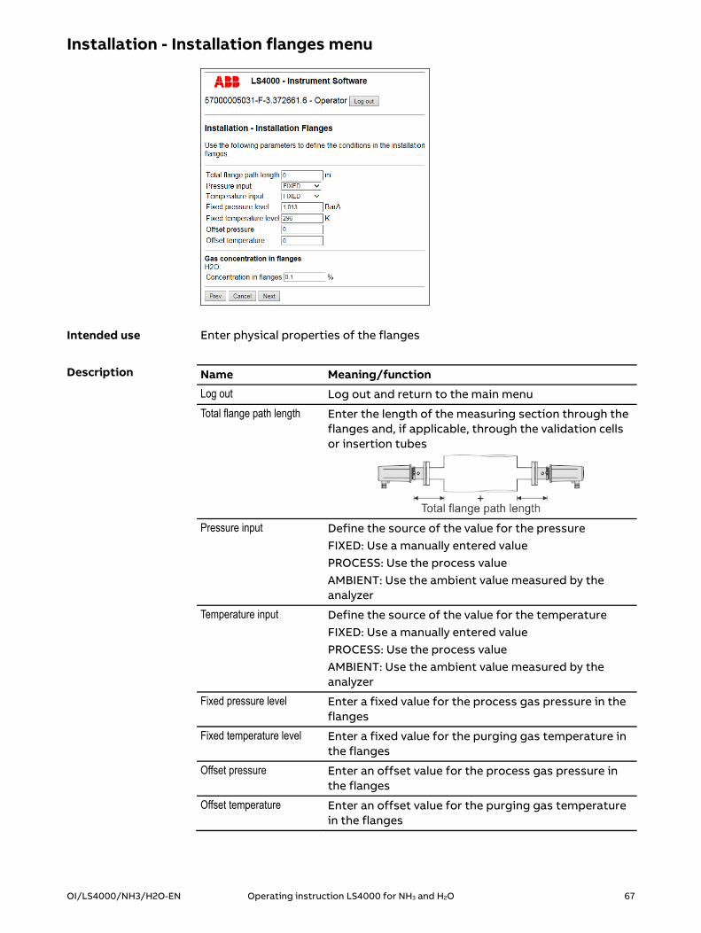
Enter physical properties of the flanges
Name Meaning/function
Log out Log out and return to the main menu
Total flange path length Enter the length of the measuring section through the flanges and, if applicable, through the validation cells or insertion tubes
Pressure input Define the source of the value for the pressure
FIXED: Use a manually entered value PROCESS: Use the process value AMBIENT: Use the ambient value measured by the analyzer
Temperature input Define the source of the value for the temperature FIXED: Use a manually entered value PROCESS: Use the process value AMBIENT: Use the ambient value measured by the analyzer
Fixed pressure level Enter a fixed value for the process gas pressure in the flanges
Fixed temperature level Enter a fixed value for the purging gas temperature in the flanges
Offset pressure Enter an offset value for the process gas pressure in the flanges
Offset temperature Enter an offset value for the purging gas temperature in the flanges
Intended use
Description

68 Operating instruction LS4000 for NH3 and H2O OI/LS4000/NH3/H2O-EN
Name Meaning/function
Concentration in flanges Enter H2O concentration in the flanges 0 % with dry N2 or 0.1 % with dry compressed air
Prev Back to previous menu
Cancel Cancel the process and exit the menu
Next Continue to the next menu
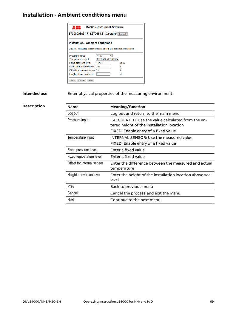
OI/LS4000/NH3/H2O-EN Operating instruction LS4000 for NH3 and H2O 69
Installation - Ambient conditions menu
Enter physical properties of the measuring environment
Name Meaning/function
Log out Log out and return to the main menu
Pressure input CALCULATED: Use the value calculated from the en-tered height of the installation location FIXED: Enable entry of a fixed value
Temperature input INTERNAL SENSOR: Use the measured value FIXED: Enable entry of a fixed value
Fixed pressure level Enter a fixed value
Fixed temperature level Enter a fixed value
Offset for internal sensor Enter the difference between the measured and actual temperature
Height above sea level Enter the height of the installation location above sea level
Prev Back to previous menu
Cancel Cancel the process and exit the menu
Next Continue to the next menu
Intended use
Description

70 Operating instruction LS4000 for NH3 and H2O OI/LS4000/NH3/H2O-EN
Installation - Channels menu
Configure the measuring channels
Name Meaning/function
Log out Log out and return to the main menu
Channel 1 Measuring channel 1
Output label NH3 - description of measuring channel 1
Output unit Unit for the value at output 1
Output tag not used
Span reference concentra-tion
Enter gas concentration in the internal validation cell Preset: 80% of the measuring range
Channel 2 Measuring channel 2
Output label H2O - description of measuring channel 2
Output unit Unit for the value at output 2
Output tag not used
Span reference concentra-tion
Enter gas concentration in the internal validation cell Preset: 80% of the measuring range
Channel 3 Measuring channel 3
Output label Transmission - description of measuring channel 3
Output unit Unit for the value at output 3
Output tag not used
Intended use
Description

OI/LS4000/NH3/H2O-EN Operating instruction LS4000 for NH3 and H2O 71
Name Meaning/function
Span reference concentra-tion
Enter gas concentration in the internal validation cell Preset: 80% of the measuring range
Channel 4 Measuring channel 4
Output label Description of measuring channel 4
Output unit Unit for the value at output 4
Output tag not used
Span reference concentra-tion
Enter gas concentration in the internal validation cell Preset: 80% of the measuring range
Prev Back to previous menu
Cancel Cancel the process and exit the menu
Next Continue to the next menu
The layout of the measuring channels presented in the figure and described in the table is an example. The actual layout is specific to each device and can differ from this.

72 Operating instruction LS4000 for NH3 and H2O OI/LS4000/NH3/H2O-EN
Installation - Analog and digital outputs menu
Configure analog and digital outputs
Name Meaning/function
Log out Log out and return to the main menu
Analog output 1 Analog output 1
Source Assign the measuring channel to the analog output Factory setting: NH3
Value at 4 mA Enter the measured value that corresponds to a cur-rent of 4 mA
Value at 20 mA Enter the measured value that corresponds to a cur-rent of 20 mA
Analog output 2 Analog output 2
Source Assign the measuring channel to the analog output Factory setting: H2O
Value at 4 mA Enter the measured value that corresponds to a cur-rent of 4 mA
Value at 20 mA Enter the measured value that corresponds to a cur-rent of 20 mA
Analog output 3 Analog output 3
Source Assign the measuring channel to the analog output Factory setting: Transmission
Intended use
Description
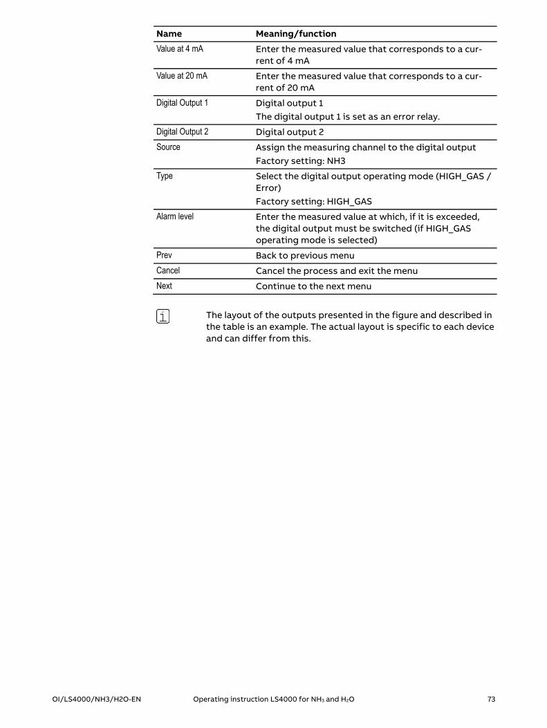
OI/LS4000/NH3/H2O-EN Operating instruction LS4000 for NH3 and H2O 73
Name Meaning/function
Value at 4 mA Enter the measured value that corresponds to a cur-rent of 4 mA
Value at 20 mA Enter the measured value that corresponds to a cur-rent of 20 mA
Digital Output 1 Digital output 1 The digital output 1 is set as an error relay.
Digital Output 2 Digital output 2
Source Assign the measuring channel to the digital output Factory setting: NH3
Type Select the digital output operating mode (HIGH_GAS / Error) Factory setting: HIGH_GAS
Alarm level Enter the measured value at which, if it is exceeded, the digital output must be switched (if HIGH_GAS operating mode is selected)
Prev Back to previous menu
Cancel Cancel the process and exit the menu
Next Continue to the next menu
The layout of the outputs presented in the figure and described in the table is an example. The actual layout is specific to each device and can differ from this.

74 Operating instruction LS4000 for NH3 and H2O OI/LS4000/NH3/H2O-EN
Installation - Save settings menu
Check entries
Save or discard entries
End configuration routine
Name Meaning/function
Log out Log out and return to the main menu
Please review … Display of the entries and settings made during the configuration routine
Save Save entries and settings End configuration routine Return to main menu
Cancel Discard entries and settings End configuration routine Return to main menu
Intended use
Description

OI/LS4000/NH3/H2O-EN Operating instruction LS4000 for NH3 and H2O 75
Maintaining and servicing the gas analyzer
Topic PageSchedule ................................................................................................................. 75
Monitoring optical transmission ....................................................................... 76
Checking and cleaning the components ........................................................... 77
Testing the analyzer ............................................................................................. 79
Connecting to the instrument software ...........................................................81
System information menu .................................................................................. 82
Instrument status menu ..................................................................................... 83
Verification of I/O modules menu .................................................................... 84
Diagnostics menu ................................................................................................. 85
Service menu ......................................................................................................... 86
Network settings menu ....................................................................................... 87
Spectrum menu .................................................................................................... 88
Logging menu ....................................................................................................... 89
Schedule
Continuous Monitoring optical transmission (see page 76)
As required Checking optical components (see page 77)
Cleaning optical components (see page 77)
Cleaning housing (see page 77)
Validating analyzer (see page 91)
Annual Testing analyzer (see page 79)
Calibrating analyzer (see page 97)
Schedule for maintenance and service

76 Operating instruction LS4000 for NH3 and H2O OI/LS4000/NH3/H2O-EN
Monitoring optical transmission
The optical transmission is monitored by reading the values for the current output that is assigned to the "Transmission" measuring channel.
Proceed as follows:
Step Procedure
1 Read the value at the current output that is assigned to the "Transmission" measuring channel.
If... then...
the value is between 5 mA and 20 mA
this means that: the optical transmission is sufficient. the optical components do not require
cleaning.
An optical transmission > 5 % is sufficient.
Monitoring optical transmission

OI/LS4000/NH3/H2O-EN Operating instruction LS4000 for NH3 and H2O 77
Checking and cleaning the components
Optical components are all the components through which the laser beam passes. Depending on the design of the analyzer, this may include:
The transmission unit lens The receiver unit lens Isolation flanges (optional) Validation cell (optional)
Proceed as follows:
Step Procedure
1 Check all optical components to ensure they are undamaged. It is advisable to perform this check when the transmission and receiver units have to be dismantled from the process for calibra-tion.
If... then...
an optical component is scratched or damaged
the optical component must be replaced.
The optical components have a sensitive coating. There is a risk of them being scratched. Do not touch the optical components with your fingers! Wear gloves! Only use approved and recommended cleaning agents and equipment when cleaning the optical components.
Approved and recommended equipment:
Soft cotton gloves Soft microfiber cloths Soft brushes Cotton swabs Cotton buds Bellows Oil-free, soft compressed air
Approved and recommended cleaning agents:
For normal soiling: Conventional washing-up liquid, diluted with distilled water.
For heavy soiling: A 1:1 mixture of clean isopropyl alcohol and distilled water.
Checking the optical components
Cleaning the optical components

78 Operating instruction LS4000 for NH3 and H2O OI/LS4000/NH3/H2O-EN
Proceed as follows:
Step Procedure
1 Remove dust, sand and other loose dirt when dry.
2 Thoroughly spray the optical component with cleaning agent.
3 Wait until the dirt has dissolved and drips off with the cleaning agent.
4 Carefully wipe away any dissolved dirt that is still adhering to the surface.
5 Rinse with distilled water.
6 Wipe the optical component dry.
Wipe the housing surfaces with a dry or damp cloth (dampened with water).
Do not use cleaning agents to clean the housing, as these may damage the seals.
Clean the housing
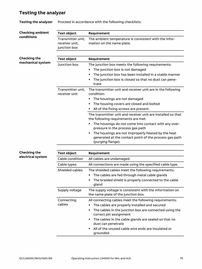
OI/LS4000/NH3/H2O-EN Operating instruction LS4000 for NH3 and H2O 79
Testing the analyzer
Proceed in accordance with the following checklists:
Test object Requirement
Transmitter unit, receiver unit, junction box
The ambient temperature is consistent with the infor-mation on the name plate.
Test object Requirement
Junction box The junction box meets the following requirements: The junction box is not damaged The junction box has been installed in a stable manner The junction box is closed so that no dust can pene-
trate
Transmitter unit, receiver unit
The transmitter unit and receiver unit are in the following condition: The housings are not damaged The housing covers are closed and bolted All of the fixing screws are present.
The transmitter unit and receiver unit are installed so that the following requirements are met: The housings do not come into contact with any over-
pressure in the process gas path The housings are not improperly heated by the heat
generated at the contact point of the process gas path (purging flange).
Test object Requirement
Cable condition All cables are undamaged.
Cable types All connections are made using the specified cable type.
Shielded cables The shielded cables meet the following requirements: The cables are fed through metal cable glands The braided shield is properly connected to the cable
gland
Supply voltage The supply voltage is consistent with the information on the name plate of the junction box.
Connecting cables
All connecting cables meet the following requirements: The cables are properly installed and secured The cables in the junction box are connected using the
correct pin assignment The cables in the cable glands are sealed so that no
dust can penetrate All of the unused cable wire ends are insulated or
grounded
Testing the analyzer
Checking ambient conditions
Checking the mechanical system
Checking the electrical system

80 Operating instruction LS4000 for NH3 and H2O OI/LS4000/NH3/H2O-EN
Test object Requirement
Cable glands The cables in the cable glands on the transmitter unit and receiver unit are fitted in a fixed position and can-not move.
Potential equali-zation
The following devices are connected via a ground cable to the local potential equalization terminal: Transmitter unit Receiver unit Junction box
The O-rings and gaskets on the flanges are subject to normal wear; the level of wear can vary heavily depending on the operating conditions (especially measuring gas composition and measuring gas temperature). Therefore the condition of the O-rings and gaskets should be checked annually.
Checking O-rings and gaskets

OI/LS4000/NH3/H2O-EN Operating instruction LS4000 for NH3 and H2O 81
Connecting to the instrument software
The instrument software is an integral component of the transmitter unit and receiver unit. It is accessed via a web browser.
The Web browsers Mozilla® Firefox® and Google ChromeTM are approved for use with the device software.
Note: Mozilla and Firefox are registered trademarks of the Mozilla Foundation. Chrome is a trademark of Google Inc.
Proceed as follows:
Step Procedure
1 Ensure that transmitter unit and receiver unit are connected to the junction box and ready for operation.
2 Ensure that a PC is connected to the junction box.
To start the instrument software, you need the IP address of the analyzer.
The factory-set IP address is provided in the analyzer data sheet.
Proceed as follows:
Step Procedure
1 Start up the PC.
2 Start up the web browser on your computer.
3 In your web browser, type the IP address of the analyzer.
The user interface of the instrument software is displayed:
Instrument software in the web browser
Connecting the devices
Starting the instrument software

82 Operating instruction LS4000 for NH3 and H2O OI/LS4000/NH3/H2O-EN
System information menu
View system information
Name Meaning/function
Log out Log out and return to the main menu
Software version Software version of the instrument software
Default settings Number of standard settings, sample component
Default settings customiza-tion
Number of customized standard settings
Transmitter firmware Firmware version of the transmitter unit
Receiver firmware Firmware version of the receiver unit
Done Exit menu
Intended use
Description

OI/LS4000/NH3/H2O-EN Operating instruction LS4000 for NH3 and H2O 83
Instrument status menu
View operating status
View measurements
Name Meaning/function
Log out Log out and return to the main menu Measurement Measurement Instrument mode Operating mode (Initialize, Measure, Fault, Service) Instrument status Operating condition (Span, Normal, Init, Calibration,
Service) Process mode Activity (Normal, Test gas N2 balance, Calibration) Absolute transmission Measured transmission value Measurement status Status of the measurement process (see page 109) Error flags Error message (see page 109). Warning flags Warning message (see page 109) Error code Error code (see page 110) Process path length Length of the measuring section through the process Process temperature Process gas temperature Process pressure Process gas pressure Channels Measuring channels NH3 Measured value NH3 H2O Measured value H2O Transmission Measured value transmission Done Exit menu Init Refresh the display Toggle span mode Pivot the NH3validation cell in and out (see page 94)
Intended use
Description

84 Operating instruction LS4000 for NH3 and H2O OI/LS4000/NH3/H2O-EN
Verification of I/O modules menu
Test function of the inputs and outputs
Configure test run
Start test run
View test result
View measured values from the T/P probes
Name Meaning/function
Log out Log out and return to the main menu
Analog and digital outputs Analog and digital outputs
Instrument mode Operating condition of the analyzer
I/O-test function Track results of the test run Example: TEST RELAY 1 CLOSED
I/O-test timeout Enter the duration of the test run
Loop out test value Enter a value for simulation of a test result
Test Start test run
External inputs External inputs
External pressure input Value for the pressure as defined in the Installation - Process parameters menu
External temperature input Value for the temperature as defined in the Installation - Process parameters menu
Done Exit menu
Intended use
Description

OI/LS4000/NH3/H2O-EN Operating instruction LS4000 for NH3 and H2O 85
Diagnostics menu
Download and save diagnostic results, configuration data and user settings from the analyzer
Upload saved configuration data to the analyzer
Name Meaning/function
Log out Log out and return to the main menu
Download diagnostics file Download and save diagnosis results from the analyz-er
Download config file Download and save configuration data from the ana-lyzer
Upload config file Enter the name of a saved configuration file
Browse… Search for a saved configuration file
> Upload saved configuration file to the analyzer.
Download user settings file
Download and save user settings from the analyzer
Done Exit menu
Intended use
Description

86 Operating instruction LS4000 for NH3 and H2O OI/LS4000/NH3/H2O-EN
Service menu
Call up the service menus
Name Meaning/function
Log out Log out and return to the main menu
Ethernet setup Call up the Network settings menu (see page 87)
Spectrum Call up the Spectrum menu (see page 88)
Calibration Call up the Calibration menu (see page 105)
Instrument Log Call up the Logging menu (see page 89)
Done Exit menu
Intended use
Description

OI/LS4000/NH3/H2O-EN Operating instruction LS4000 for NH3 and H2O 87
Network settings menu
Configure the network
Name Meaning/function
Log out Log out and return to the main menu
Automatic IP address 0: Enable entry of a fixed IP address 1: Search DHCP server
Specify IP address Enter the IP address The factory-set IP address is provided in the analyzer data sheet.
Specify netmask Enter the netmask
Specify gateway Enter the gateway
Save Save settings and exit the menu
Cancel Cancel the process and exit the menu
If the IP address has been changed, a restart of the gas analyzer is required afterwards. To do so, switch off the gas analyzer and power it back up again. Afterwards, the gas analyzer can be reached using the changed IP address.
Intended use
Description
Restart the gas analyzer
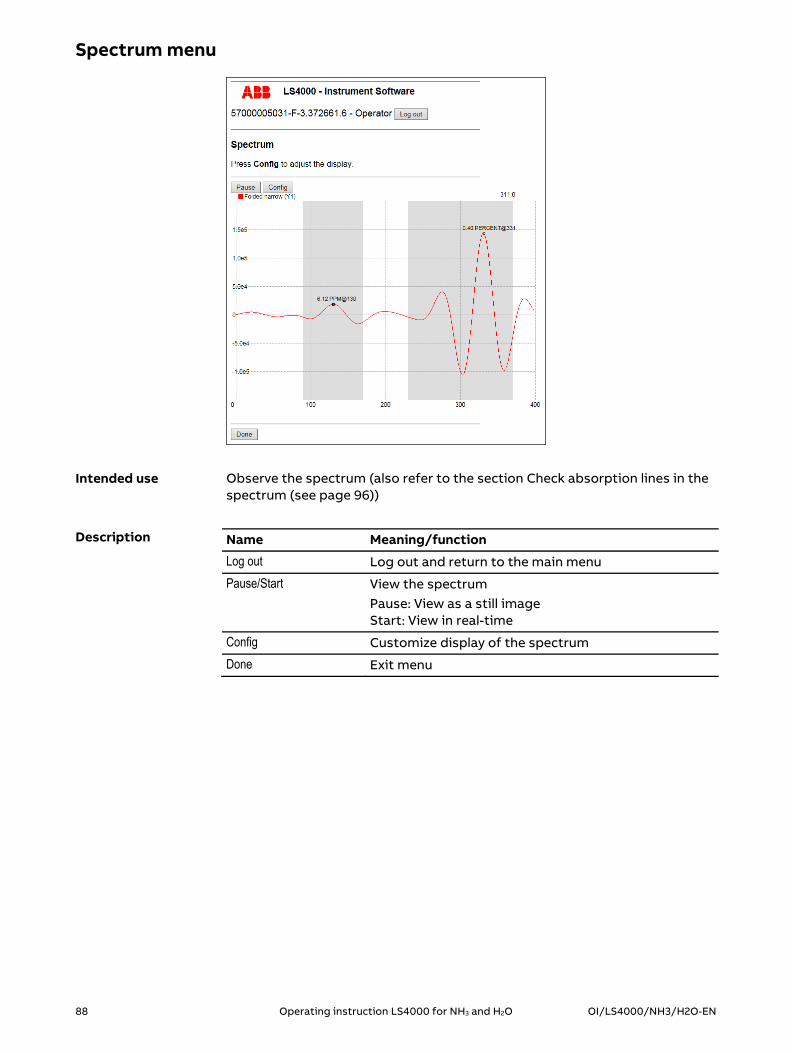
88 Operating instruction LS4000 for NH3 and H2O OI/LS4000/NH3/H2O-EN
Spectrum menu
Observe the spectrum (also refer to the section Check absorption lines in the spectrum (see page 96))
Name Meaning/function
Log out Log out and return to the main menu
Pause/Start View the spectrum Pause: View as a still image Start: View in real-time
Config Customize display of the spectrum
Done Exit menu
Intended use
Description

OI/LS4000/NH3/H2O-EN Operating instruction LS4000 for NH3 and H2O 89
Logging menu
Activate or deactivate the measurements log
Define structure and content of the log file
Name Meaning/function
Log out Log out and return to the main menu
Configuration Configuration
Sample data every Define the frequency of log file updates
Continuous logging Continuous overwriting of the log file 1: activate or 0: deactivate
Log file structure Structure of the log file
Enable file header Header 1: activate or 2: deactivate
Time format string Define the date and time format
Format string Define the measured value format
CSV separator Define the separator for data fields
Decimal separator Define the decimal separator
Data sources Data sources
Source Select measuring channels for entries in the log file
Status Display of the logging status
Internal log size Maximum size of the log file
Instrument time Current date and time in the analyzer
Log last updated Date and time at which the log file was last updated
Refresh Update status display
Logging control Control the logging
Intended use
Description

90 Operating instruction LS4000 for NH3 and H2O OI/LS4000/NH3/H2O-EN
Name Meaning/function
Start Start logging
Stop Stop logging
Restart Restart logging
Download internal log file Download and save the log file from the analyzer
Done Exit menu

OI/LS4000/NH3/H2O-EN Operating instruction LS4000 for NH3 and H2O 91
Validating and calibrating the gas analyzer
Topic PageValidating the gas analyzer ................................................................................. 91
Calibrating the gas analyzer ............................................................................... 97
Validating the gas analyzer
Topic PagePreparing for validation ....................................................................................... 91
Validation ............................................................................................................... 93
Validate using the internal validation cell ........................................................ 94
Check absorption lines in the spectrum .......................................................... 96
Preparing for validation
If... then...
no validation cells are inte-grated in the process
the validation must be performed on a separate validation set.
validation cells are inte-grated in the process
the validation can be performed on the process.
The separate validation set is identical to the calibration set (see section Installing the calibration set (see page 97)).
The diagram shows the positioning of the validation cell in the process:
No. Meaning
1 Transmitter unit
2 Validation cell
3 Test gas supply and discharge
4 Purging flange
5 Process
6 Purging flange
7 Receiver unit
Design
Separate validation set
Validation cell in the process

92 Operating instruction LS4000 for NH3 and H2O OI/LS4000/NH3/H2O-EN
Proceed as follows:
Step Procedure
1 Connect a discharge line to the test gas output.
2 Connect a test gas to the test gas input.
The validation is used to check the functional capability of the analyzer.
Due to the gasket materials used in the transmitter unit and the receiver unit, it is recommended not to apply test gas with more than 50 ppm NH3. The following table shows the measured value change which should be achieved depending on the test gas concentration and the process path length (OPL).
MR 5 ppm 7.5 ppm 10 ppm 12.5 ppm
OPL cv ct cv ct cv ct cv ct
0.5 m 4 21 6 32 8 42 10 53
1.0 m 4 42 - - - - - -
MR 5 ppm 7.5 ppm 10 ppm 12.5 ppm 15 ppm
OPL cv ct cv ct cv ct cv ct cv ct
0.5 m 4 13 6 20 8 26 10 32 12 39
1.0 m 4 26 6 39 8 52 - - - -
1.5 m 4 39 - - - - - - - -
2.0 m 4 52 - - - - - - - -
MR Measuring range
OPL Optical path length
cv resulting total concentration in the process in ppm
ct concentration of the test gas to be used for validation in ppm
Test gas for validation
Validation with a length of 100 mm
Two validation cells with a total length of 160 mm
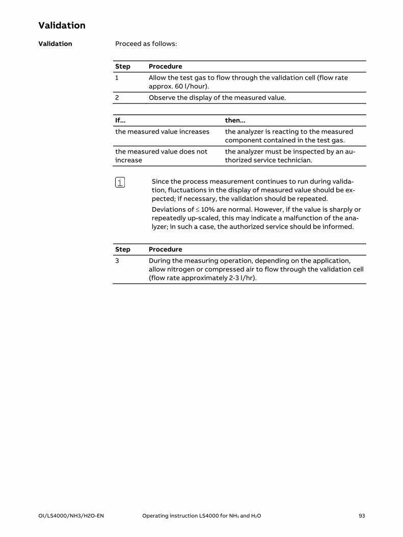
OI/LS4000/NH3/H2O-EN Operating instruction LS4000 for NH3 and H2O 93
Validation
Proceed as follows:
Step Procedure
1 Allow the test gas to flow through the validation cell (flow rate approx. 60 l/hour).
2 Observe the display of the measured value.
If... then...
the measured value increases the analyzer is reacting to the measured component contained in the test gas.
the measured value does not increase
the analyzer must be inspected by an au-thorized service technician.
Since the process measurement continues to run during valida-tion, fluctuations in the display of measured value should be ex-pected; if necessary, the validation should be repeated.
Deviations of 10% are normal. However, if the value is sharply or repeatedly up-scaled, this may indicate a malfunction of the ana-lyzer; in such a case, the authorized service should be informed.
Step Procedure
3 During the measuring operation, depending on the application, allow nitrogen or compressed air to flow through the validation cell (flow rate approximately 2-3 l/hr).
Validation

94 Operating instruction LS4000 for NH3 and H2O OI/LS4000/NH3/H2O-EN
Validate using the internal validation cell
A validation cell is integrated in the transmitter unit. It can be swiveled into the beam path to easily validate the functioning of the analyzer. The valida-tion cell applied generates an NH3set point of 80% of the upper range value.
Note: Validation of the sample component H2O is not required. It is sufficient to check the position of the water line in the spectrum (see section Check absorption lines in the spectrum (see page 96)).
Proceed as follows:
Step Procedure
Prerequisite: The connection to the instrument software is estab-lished and the user is logged in as Operator.
1 In the main menu, click on “Instrument status”. The Instrument status menu is displayed.
The measured value now displayed for NH3 (1.61 ppm in the exam-ple) will be automatically subtracted from the measured value displayed later (see step 2).
Simplified validation
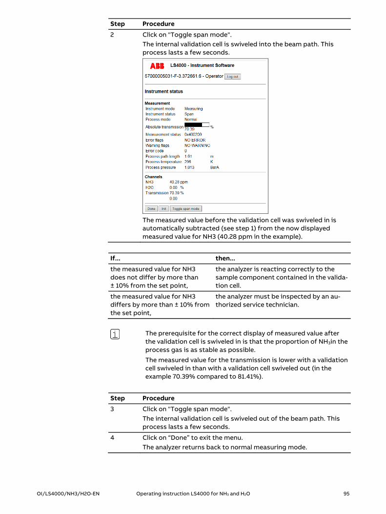
OI/LS4000/NH3/H2O-EN Operating instruction LS4000 for NH3 and H2O 95
Step Procedure
2 Click on "Toggle span mode". The internal validation cell is swiveled into the beam path. This process lasts a few seconds.
The measured value before the validation cell was swiveled in is automatically subtracted (see step 1) from the now displayed measured value for NH3 (40.28 ppm in the example).
If... then...
the measured value for NH3 does not differ by more than ± 10% from the set point,
the analyzer is reacting correctly to the sample component contained in the valida-tion cell.
the measured value for NH3 differs by more than ± 10% from the set point,
the analyzer must be inspected by an au-thorized service technician.
The prerequisite for the correct display of measured value after the validation cell is swiveled in is that the proportion of NH3in the process gas is as stable as possible.
The measured value for the transmission is lower with a validation cell swiveled in than with a validation cell swiveled out (in the example 70.39% compared to 81.41%).
Step Procedure
3 Click on "Toggle span mode". The internal validation cell is swiveled out of the beam path. This process lasts a few seconds.
4 Click on “Done” to exit the menu. The analyzer returns back to normal measuring mode.

96 Operating instruction LS4000 for NH3 and H2O OI/LS4000/NH3/H2O-EN
Checking absorption lines in the spectrum
To test the functioning of the analyzer, you can check the positions of the absorption lines in the spectrum. Proceed as follows:
Step Procedure Prerequisite: The connection to the instrument software is estab-
lished and the user is logged in as Operator. If there is no water in the process gas, the purging flanges need to be purged with compressed air or with ambient air.
1 In the main menu, click on “Service”. The "Service" menu is displayed.
2 Click on "Spectrum" in the "Service" menu. The "Spectrum" menu is displayed.
Checking the position of the water line in the spectrum:
The H2O line can be found in the right-hand gray-shaded area of the spectrum. The marking on the top shows the current measured value of the H2O component, as well as the position of the line in the spectrum. If the position is not at 330±1, the analyzer should be inspected by an authorized service technician. Checking the position of the ammoniac line in the spectrum: The NH3 line can be found in the left-hand gray-shaded area of the spectrum. The marking on the top shows the current measured value of the NH3 component, as well as the position of the line in the spectrum. If the position is not at 130±1, the analyzer should be inspected by an authorized service technician.
3 Click on “Done” to exit the menu. The analyzer returns back to normal measuring mode. Make sure that purging flanges are purged.
Functional testing
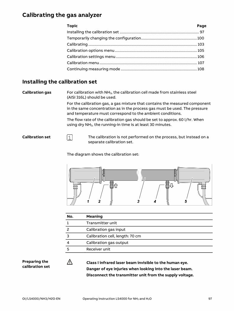
OI/LS4000/NH3/H2O-EN Operating instruction LS4000 for NH3 and H2O 97
Calibrating the gas analyzer
Topic PageInstalling the calibration set .............................................................................. 97
Temporarily changing the configuration ....................................................... 100
Calibrating ........................................................................................................... 103
Calibration options menu ................................................................................. 105
Calibration settings menu ................................................................................ 106
Calibration menu ................................................................................................ 107
Continuing measuring mode ........................................................................... 108
Installing the calibration set
For calibration with NH3, the calibration cell made from stainless steel (AISI 316L) should be used.
For the calibration gas, a gas mixture that contains the measured component in the same concentration as in the process gas must be used. The pressure and temperature must correspond to the ambient conditions.
The flow rate of the calibration gas should be set to approx. 60 l/hr. When using dry NH3, the running-in time is at least 30 minutes.
The calibration is not performed on the process, but instead on a separate calibration set.
The diagram shows the calibration set:
No. Meaning
1 Transmitter unit
2 Calibration gas input
3 Calibration cell, length: 70 cm
4 Calibration gas output
5 Receiver unit
Class I infrared laser beam invisible to the human eye. Danger of eye injuries when looking into the laser beam. Disconnect the transmitter unit from the supply voltage.
Calibration gas
Calibration set
Preparing the calibration set

98 Operating instruction LS4000 for NH3 and H2O OI/LS4000/NH3/H2O-EN
Proceed as follows:
Step Procedure
1 Disconnect the analyzer from the supply voltage.
2 Disassemble the transmitter unit and the receiver unit from the process. Make sure that no process gas is able to leak out of the purging flanges.
The transmitter unit and receiver unit are installed using exactly the same steps.
No. Meaning
1 Calibration cell, length: 70 cm
2 Purging flange flat gasket
3 Clamp
4 Transmitter unit or receiver unit
5 Calibration gas input or output
Proceed as follows:
Step Procedure
1 Place the purging flange flat gasket in the groove of the calibration cell.
2 Place the transmitter unit or the receiver unit onto the front side of the calibration cell.
3 Attach the transmitter unit and the receiver unit using the clip.
Installing the calibration set

OI/LS4000/NH3/H2O-EN Operating instruction LS4000 for NH3 and H2O 99
Proceed as follows:
Step Procedure
1 Connect the supply voltage to the analyzer.
2 Connect the calibration gas to the calibration gas input.
3 Connect a discharge line to the calibration gas output.
4 Open the junction box.
5 Connect a PC to the junction box (see section Connecting a PC to the junction box (see page 55)).
The analyzer is now ready for the calibration process.
Establishing the connections

100 Operating instruction LS4000 for NH3 and H2O OI/LS4000/NH3/H2O-EN
Temporarily changing the configuration
Only the NH3 sample component needs to be calibrated; it is per-formed using the instrument software.
Given the measuring principle, the H2O sample component does not need to be calibrated. The process of checking the position of the water line in the spectrum is explained in section Checking absorption lines in the spectrum (see page 96).
Proceed as follows:
Step Procedure
1 Start up the PC.
2 Start up the web browser on your computer.
3 In your web browser, type the IP address of the analyzer. The connection to the instrument software is now established. The Main menu is displayed.
Proceed as follows:
Step Procedure
1 Enter the operator password. The operator password is "xs2ls".
2 Click on "Log in". You are now logged in as an operator. The expanded Main menu is displayed.
For the calibration process, you must temporarily change the con-figuration of the analyzer.
Once the calibration process is completed, the original configura-tion must be restored.
In order to facilitate restoration of the original configuration, choose one of the following methods:
Make a note of the original settings before each change. Before each change, save a screenshot of the original settings.
Step Procedure
1 Click on "Installation". The Installation procedure menu (see page 63) is displayed.
2 Click on "Next" to start the configuration routine. The Installation - Cable length menu (see page 64) is displayed.
Preface
Starting the instrument software
Logging in
Adjusting the configuration
Installation procedure menu
OI/LS4000/NH3/H2O-EN Operating instruction LS4000 for NH3 and H2O 101
Step Procedure
3 Leave all values unchanged.
4 Click on "Next". The Installation - Process parameters menu (see page 65) is dis-played.
Make the following settings:
Process path length see the following clarifications
Pressure input FIXED
Temperature input FIXED
Fixed pressure level Enter the pressure value
Fixed temperature level Enter the temperature value
Enable process broadening No
Due to the gasket materials used in the transmitter unit and the receiver unit, it is recommended not to apply test gas with more than 50 ppm NH3.
To be able to perform calibration for measuring ranges > 50 ppm NH3, the standard process path length (OPL) of 0.7 m needs to be appropriately re-duced at a consistent test gas concentration of 40 ppm NH3.
In the process, the product of the OPL and cmeas.value must always amount to 0.7 * 40 ppm * m. Specified in the following table are:
Concentration of the test gas ctest gas and the process path length OPL to be entered for 80% of the measuring
range, as well as the resulting total concentration cmeas.value
Measuring range ctest gas OPL cmeas.value
20 ppm 16 ppm 0.7 m 16 ppm
50 ppm 40 ppm 0.7 m 40 ppm
100 ppm 40 ppm 0.35 m 80 ppm
200 ppm 40 ppm 0.175 m 160 ppm
Step Procedure
5 Leave the other settings unchanged.
6 Click on "Next". The Installation - Installation flanges menu (see page 67) is dis-played.
Installation - Cable length menu
Installation - Process parameters menu
Clarifications regarding the “process path length” parameter
102 Operating instruction LS4000 for NH3 and H2O OI/LS4000/NH3/H2O-EN
Make the following settings:
Total flange path length 0 (zero) m
Concentration in flanges 0 (zero) %
Step Procedure
7 Leave the other settings unchanged.
8 Click on "Next". The Installation - Ambient conditions menu (see page 69) is dis-played.
Step Procedure
9 Leave all values unchanged.
10 Click on "Next". The Installation - Channels menu (see page 70) is displayed.
Step Procedure
11 Leave all values unchanged.
12 Click on "Next". The Installation - Analog and digital outputs menu (see page 72) is displayed.
Step Procedure
13 Leave all values unchanged.
14 Click on "Next". The Installation - Save settings menu (see page 74) is displayed.
Step Procedure
15 Check all the settings.
If... then...
a setting is incorrect the configuration routine must be repeat-ed. To repeat the adjustment of the configura-tion, click on "Cancel". All changes are dis-carded. The Installation procedure menu is displayed. Repeat the configuration rou-tine.
all settings are correct Click on "Save". The settings are saved. The Main menu is displayed. The analyzer is ready for calibra-tion.
Installation - Installation flanges menu
Installation - Ambient conditions menu
Installation - Channels menu
Installation - Analog and digital outputs menu
Installation - Save settings menu

OI/LS4000/NH3/H2O-EN Operating instruction LS4000 for NH3 and H2O 103
Calibration
Proceed as follows:
Step Procedure
1 Click on "Service". The Service menu (see page 86) is displayed.
2 Click on "Calibration". The Calibration options menu (see page 105) is displayed.
3 Click on "Start user calibration".
The Calibration settings menu (see page 106) is displayed.
Step Procedure
4 Enter the parameters for the calibration procedure:
Gas to calibrate Calibration gas (NH3)
Concentration in gas cell Calibration gas concentration in the calibra-tion cell
Unit of calibration gas Unit for displaying the calibration gas con-centration (ppm for NH3)
Averaging time Measuring duration for determining the average value (typically 30 s, max. 60 s.)
Calibration signature User name (this entry is optional)
Opening the calibration menu
Entering calibration data

104 Operating instruction LS4000 for NH3 and H2O OI/LS4000/NH3/H2O-EN
Step Procedure
5 Click on "Next". The Calibration menu (see page 107) is displayed.
Step Procedure
6 Allow the calibration gas to flow through the calibration cell (flow rate approx. 60 l/hr).
7 Observe the display of measured value. When the measured value is stable, click on "Start". The calibration process starts.
8 Read the measurements taken during the calibration process.
9 Observe the progress bar that displays the progress of the calibra-tion process. When the progress bar shows 100 %, the calibration process is complete.
10 Click on "Done". The Main menu is displayed.
11 Disassemble the calibration set. Resume measuring mode.
Performing calibration

OI/LS4000/NH3/H2O-EN Operating instruction LS4000 for NH3 and H2O 105
Calibration options menu
Start calibration
Reset calibration to factory settings
Name Meaning/function
Log out Log out and return to the main menu
Reset user calibration Reset calibration to factory settings
Start user calibration Call up the Calibration settings menu (see page 106).
Cancel Exit menu
Intended use
Description

106 Operating instruction LS4000 for NH3 and H2O OI/LS4000/NH3/H2O-EN
Calibration settings menu
Enter parameters for the calibration process
Name Meaning/function
Log out Log out and return to the main menu
Gas to calibrate Select calibration gas
Concentration in gas cell Enter the calibration gas concentration in the calibra-tion cell
Unit of calibration gas Select the unit for displaying the calibration gas con-centration
Averaging time Enter the measurement duration for determining the average value
Calibration signature Enter a user name (optional)
Cancel Exit menu
Next Call up the Calibration menu (see page 107)
Intended use
Description

OI/LS4000/NH3/H2O-EN Operating instruction LS4000 for NH3 and H2O 107
Calibration menu
View operating status
Start calibration process
Name Meaning/function
Log out Log out and return to the main menu
Instrument status Instrument status:
Instrument mode Operating condition
Process mode Activity
Process path length Process path length (Enter in Installation - Process parameters menu)
Process temperature Process gas temperature (Enter in Installation - Process parameters menu)
Process pressure Process gas pressure (Enter in Installation - Process parameters menu)
NH3 Calibration gas concentration (NH3)
H2O Calibration gas concentration (H2O)
Transmission Transmission value
Calibration progress Calibration process
Calibration progress Progress of the calibration process
Start Start calibration process
Cancel Cancel the calibration process
Done Exit menu
Intended use
Description

108 Operating instruction LS4000 for NH3 and H2O OI/LS4000/NH3/H2O-EN
Continuing measuring mode
Class I infrared laser beam invisible to the human eye. Danger of eye injuries when looking into the laser beam. Disconnect the transmitter unit from the supply voltage.
Proceed as follows:
Step Procedure
1 Disconnect the analyzer from the supply voltage.
2 Disconnect the discharge line from the calibration gas output.
3 Disconnect the calibration gas from the calibration gas input.
4 Remove the transmitter unit and the receiver unit from the calibra-tion cell.
Proceed as follows:
Step Procedure
1 Install the transmitter unit and the receiver unit back on the pro-cess (see Installing the transmitter unit and receiver unit (see page 36)). New self-locking nuts must be used for mounting on the process.
2 Check the analyzer in accordance with the checklists in section Checking and approving the gas analyzer (see page 51).
3 Re-connect the analyzer to the supply voltage.
Proceed as follows:
Step Procedure
1 Restore the original configuration in the configuration routine (see Temporarily changing the configuration (see page 100)).
2 Close the web browser.
3 Shut down the PC.
4 Disconnect the PC from the junction box by disconnecting the adapter board from the terminal strip.
5 Close the junction box.
The analyzer is ready to use again.
Disassembling the calibration set
Attaching and connecting the components to the process
Restoring the configuration

OI/LS4000/NH3/H2O-EN Operating instruction LS4000 for NH3 and H2O 109
Recognizing and resolving errors
Topic PageError messages in the "Measuring” operating condition ........................... 109
Error messages in the "Malfunction" operating condition ......................... 110
Error messages in "Measuring" mode
Measurement status Meaning and cause How to resolve the error
0x001 LOW_TRANSMISSION_WARNING The transmission of the laser beam is not sufficient to evaluate the meas-urement results.
Clean all optical components through which the laser beam passes
Check and correct the alignment of the transmitter unit in relation to the receiver unit
0x004 TEMP_ERROR The instrument has recognized an unstable temperature in the trans-mitter unit or receiver unit.
If the error occurs repeatedly or continuously: Have the error re-solved by authorized service per-sonnel
0x008 BEAM_BLOCK_ERROR The laser beam does not reach the receiver unit.
Clean all optical components through which the laser beam passes
Remove any foreign matter that may be present and that may in-terrupt the transmission of the la-ser beam
Check and correct the alignment of the transmitter unit in relation to the receiver unit
0x010 BEAM_BLOCK_WARNING The laser beam is sometimes not able to reach the receiver unit.
Remove any foreign matter that may be present and that may in-terrupt the transmission of the la-ser beam
Check that the transmitter unit and receiver unit are securely in-stalled
0x020 CHECKSUM_ERROR Data transmission between the transmitter unit and receiver unit is disrupted.
Check and repair the electrical connection between the transmit-ter unit and receiver unit
0x040 TIMING_ERROR The analyzer is overloaded.
Reduce the measurement period for determining the average value
0x080 SAMPLING_OVERFLOW_ERROR Data transmission between the transmitter unit and receiver unit is disrupted.
Check and repair the electrical connection between the transmit-ter unit and receiver unit
All others Unknown or cannot be resolved on your own
Inform authorized service person-nel of the error code
110 Operating instruction LS4000 for NH3 and H2O OI/LS4000/NH3/H2O-EN
Error messages in "Malfunction" status
The analyzer goes into the “Malfunction” operating condition if an error oc-curs during initialization of the analyzer. Since the analyzer runs through the initialization routine several times, it can take up to five minutes until the analyzer switches to the “Malfunction” operating condition.
The analyzer goes into the “Malfunction” operating condition if an error oc-curs in the “Measuring” operating condition and an initialization has therefore been launched.
The analyzer can quit the “Malfunction” operating condition only if the error has been eliminated (see following table), and is no longer pending during the subsequent initialization.
Error code Meaning and cause How to resolve the error
3 MEMORY ALLOC FAILURE The internal measured value memory is full.
Shut down the analyzer. Restart the analyzer.
8 ERROR INITIALIZING RX UNIT Data transmission between the transmit-ter unit and receiver unit is disrupted.
Check and repair the electrical connec-tion between the transmitter unit and receiver unit.
9 SYSTEM IS UNCONFIGURED The analyzer is not fully configured.
Configure the analyzer using the device software.
10 SETTINGS IS CORRUPTED The analyzer is not configured correctly.
Correct the configuration of the ana-lyzer using the device software.
11 SETTINGS OUT OF BOUNDS The configuration contains parameters that are outside the permitted value rang-es.
Correct the configuration of the ana-lyzer using the device software.
13 TEMP REG. TIMEOUT The temperature in the transmitter unit or in the receiver unit may be too high be-cause the temperature regulation failed.
Cool the unit using one of the following methods: Shielding from the heat source Improving the air circulation
14 BEAM BLOCK The laser beam does not reach the receiver unit.
Clean all optical components through which the laser beam passes
Remove any foreign matter that may be present and that may interrupt the transmission of the laser beam
Check and correct the alignment of the transmitter unit in relation to the re-ceiver unit
Malfunction operating condition

OI/LS4000/NH3/H2O-EN Operating instruction LS4000 for NH3 and H2O 111
Error code Meaning and cause How to resolve the error
17 LINE TRACKING FAILURE The analyzer has detected a spectroscopy error with one of the following causes: Unknown process gas in process Incorrect wavelength The operating temperature of the
transmitter unit is outside the permit-ted range
Analyzer malfunction
Disconnect the analyzer from the sup-ply voltage. Apply test gas (in the pro-cess or in a validation cell). For the test gas, use a gas mixture that contains the measured component in a concentra-tion suitable for generating a signifi-cant change in the measured value dis-play. Initialize the analyzer.
If the error message occurs again, con-tact the authorized service personnel.
21 RX WRITE FAIL Data transmission between the transmit-ter unit and receiver unit is disrupted.
Check and repair the electrical connec-tion between the transmitter unit and receiver unit
22 RX READ FAIL Data transmission between the transmit-ter unit and receiver unit is disrupted.
Check and repair the electrical connec-tion between the transmitter unit and receiver unit
24 TX FIRMWARE TOO OLD The transmitter unit has an earlier version of the firmware that is not compatible with the device software.
Contact the authorized service person-nel.
25 TX FIRMWARE TOO NEW The transmitter unit has a later version of the firmware that is not compatible with the device software.
Contact the authorized service person-nel.
26 RX FIRMWARE TOO OLD The receiver unit has an earlier version of the firmware that is not compatible with the instrument software.
Contact the authorized service person-nel.
27 RX FIRMWARE TOO NEW The receiver unit has a later version of the firmware that is not compatible with the instrument software.
Contact the authorized service person-nel.
30 DMA RAMP TRANSFER Data transmission between the transmit-ter unit and receiver unit is disrupted.
Check and repair the electrical connec-tion between the transmitter unit and receiver unit
32 LASER TEMP TOO HIGH The temperature in the transmitter unit or in the receiver unit has exceeded the maximum permitted value.
Cool the unit using one of the following methods: Shielding from the heat source Improving the air circulation
If the error message persists or a sig-nificantly incorrect measurement result is displayed, contact the authorized service personnel.
All others Unknown or cannot be resolved on your own
Inform authorized service personnel of the error code

112 Operating instruction LS4000 for NH3 and H2O OI/LS4000/NH3/H2O-EN
Gas analyzer shutdown
Topic PageEnding operation and shutting down the gas analyzer ............................... 112
Disassemble gas analyzer .................................................................................. 113
Ending operation and shutting down the gas analyzer
Proceed as follows:
Step Procedure
1 Disconnect the analyzer from the supply voltage.
Proceed as follows:
Step Procedure
1 Disconnect the transmitter unit from the junction box.
2 Disconnect the transmitter unit from the potential equalization terminal.
3 Disconnect the receiver unit from the junction box.
4 Disconnect the receiver unit from the potential equalization ter-minal.
Ending operation
Shutting down the gas analyzer

OI/LS4000/NH3/H2O-EN Operating instruction LS4000 for NH3 and H2O 113
Disassembling the gas analyzer
Before uninstalling, shut down the analyzer (see Ending operation and shutting down the gas analyzer (see page 112).
The transmitter unit and receiver unit are dismantled using exactly the same steps.
No. Meaning
1 Purging flange flat gasket
2 Clamp
3 Transmitter unit or receiver unit
Disassemble the transmitter unit and receiver unit as follows:
Step Procedure
1 Hold the transmitter unit or the receiver unit firmly.
2 Loosen and remove the clamp 2 of the transmitter unit or the re-ceiver unit.
3 Remove the transmitter unit or receiver unit from the purging flange.
4 Remove the purging flange flat gasket 1 from the groove of the purging flange.
5 Disassemble the purging flanges and close the installation flange openings.
Disassembling the transmitter unit and receiver unit

—
ABB Automation GmbH Measurement & Analytics Stierstädter Str. 5 60488 Frankfurt am Main Germany Fax: +49 69 7930-4566 Mail: [email protected] abb.com/analytical
OI/
LS40
00
/NH
3/H
2O-E
N 0
8.20
17
— We reserve the right to make technical changes or modify the contents of this document without prior notice. With regard to purchase orders, the agreed particulars shall prevail. ABB does not accept any responsibility whatsoever for potential errors or possible lack of information in this document. We reserve all rights in this document and in the subject matter and illustrations contained therein. Any reproduction, disclosure to third parties or utilization of its contents – in whole or in parts – is forbidden without prior written consent of ABB. © ABB 2017


