ABC Combi Gas Oven ABC7G ML-137715 - NOTICE - This Manual is prepared for the use of trained Vulcan Service Technicians and should not be used by those not properly qualified. This manual is not intended to be all encompassing. If you have not attended a Vulcan Service School for this product, you should read, in its entirety, the repair procedure you wish to perform to determine if you have the necessary tools, instruments and skills required to perform the procedure. Procedures for which you do not have the necessary tools, instruments and skills should be performed by a trained Vulcan Service Technician. The reproduction, transfer, sale or other use of this Manual, without the express written consent of Vulcan, is prohibited. This manual has been provided to you by ITW Food Equipment Group LLC ("ITW FEG") without charge and remains the property of ITW FEG, and by accepting this manual you agree that you will return it to ITW FEG promptly upon its request for such return at any time in the future. SERVICE MANUAL A product of Vulcan-Hart 3600 North Point Blvd Baltimore, MD 21222 F45491 Rev. A (0215)
Transcript
ABC Combi Gas OvenABC7G ML-137715
- NOTICE -This Manual is prepared for the use of trained Vulcan ServiceTechnicians and should not be used by those not properlyqualified.
This manual is not intended to be all encompassing. If you havenot attended a Vulcan Service School for this product, you shouldread, in its entirety, the repair procedure you wish to perform todetermine if you have the necessary tools, instruments and skillsrequired to perform the procedure. Procedures for which you donot have the necessary tools, instruments and skills should beperformed by a trained Vulcan Service Technician.
The reproduction, transfer, sale or other use of this Manual,without the express written consent of Vulcan, is prohibited.
This manual has been provided to you by ITW Food EquipmentGroup LLC ("ITW FEG") without charge and remains the propertyof ITW FEG, and by accepting this manual you agree that you willreturn it to ITW FEG promptly upon its request for such return atany time in the future.
SERVICE MANUAL
A product of Vulcan-Hart 3600 North Point Blvd Baltimore, MD 21222F45491 Rev. A (0215)
GeneralThis manual is for ABC7 Combi ovens. Ovensfeature a powered vent damper, advanced digitalcontrol panel with digital display for setting cookTEMPERATURE, TIME, and HUMIDITY.
HeatingThe ABC Combi oven reaches bakingtemperature of 350°F at 0% humidity inapproximately 5 ½ to 6 minutes; however, a 20minute preheat is recommended.
Combi OvensCombi ovens provide convection heat, steamheat or a combination of both in a singlecompartment cooking chamber. Humidification isprovided by water injection into oven cavity.Water is injected by means of an internal nozzle,it vaporizes on contact with hot interior surfaces.
Steam SystemAll combi ovens come with a boiler less flashsteaming system which provides a quickresponse time as well as excellent cookingresults.
All information, illustrations and specificationscontained in this manual are based on latestproduct information available at time of release.
OPERATION, CLEANING ANDMAINTENANCE
Refer to Installation & Operation Manual (F47110) forspecific operating instructions.
TOOLS
Standard
1. Standard set of hand tools.
2. Metric set of hand tools.
3. VOM with measuring micro amp current tester.(Any VOM with a sensitivity of at least 20,000ohms per volt can be used.)
2. M6 socket head cap screw 3" long (hardenedblack oxide finish) for removing convection fanfrom motor shaft.
3. Gear puller to remove CONVECTION FANMOTOR.
4. USB Drive (Part # 00-443444)
LUBRICATION
1. Ovens have self-lubricating composite bearings.No lubrication required.
2. Anti seizing compound.
WATER QUALITY STATEMENT
The fact that a water supply is potable is no guaranteethat it is suitable for steam generation. Proper waterquality can improve the taste of the food prepared inthe oven, reduce scale build-up or corrosion, andextend equipment life. Local water conditions varyfrom one location to another and can changethroughout the year. The recommended watertreatment for effective and efficient use of thisequipment will vary depending on the local waterconditions. Your water supply must be within thegeneral guidelines outlined in the chart below at alltimes during use of this machine or service issues notcovered under warranty may result.
Water hardness should be treated by removing theimpurities (water softener with carbon block ordechlorinator and/or in-line water treatment). Lowwater hardness may also require a water treatmentsystem to reduce potential corrosion. Water treatmenthas been shown to reduce costs associated withmachine cleaning, reduce deliming and reducecorrosion of metallic surfaces.
Daily washing and rinsing of the cavity is required. Insome cases it may be needed more than once a dayto prevent compounding of contaminants depositedinside cavity even with acceptable filtration. Failure towash and rinse down the cavity daily could result indamage of the oven cavity and interior parts. AReverse Osmosis water treatment system can beinstalled to eliminate chlorides or other contaminatesfrom the water if needed.
ABC Combi Gas Oven - GENERAL
Page 5 of 88 F45491 Rev. A (0215)
NOTE: Failure to properly maintain water quality orpreventative procedures for water can lead to issuesnot covered under warranty.
WATER SUPPLY GENERAL GUIDELINES 1
Supply Pressure(dynamic flow) 30-60 psig
Hardnessless than 3 grains (17.1ppm = 1 grain ofhardness)
Silica less than 13 ppm
Chloramines 2 zero
Chlorides 2 less than 30 ppm 3
Total Chlorine 4 zero
PH range 7-8
Un-Dissolved Solids less than 5 microns
1 Testing of water is always done AFTER waterfilter or water treatment used. Water quality doeschange with usage and should be checked afteridle times to see if the condition worsens .2 A carbon block filter system should always beused to remove Chlorine and Chloramine. If awater softener is used, a carbon block is stillrequired. Check with your local water treatmentspecialist for proper sizing and replacementintervals for the carbon block cartridge.3 If the Chlorides exceed 30 ppm and the oven isused more than 8 hours during the day in steamor combination mode the cavity will requirerinsing every 8 hours. Failure to do so will resultin corrosion and rusting of the oven cavity andinterior parts. A Reverse Osmosis water treatmentsystem can be installed to eliminate chloridesfrom the water and reduce the hardness.Preventative washing and rinsing may be neededmore than once a day to prevent compounding ofcontaminants inside cavity.4 Total Chlorine of 4.0 ppm is the max limit for thebuilding water supply. A carbon block filter muststill be used to remove all Chlorine andChloramines from the water. Failure to do so willresult in corrosion and rust in the cooking cavitywhich is not covered under warranty.
SPECIFICATIONS
Data
Appliances equipped with a flexibleelectric supply cord are provided with a three pronggrounding plug. It is imperative that this plug beconnected into a properly grounded three prongreceptacle. If the receptacle is not the propergrounding type, contact an electrician. Do not removegrounding prong from this plug.
Electrical and groundingconnections must comply with the applicable portionsof the National Electrical Code and / or other localelectrical codes.
NOTE: Do not use GFI outlets. The spark ignition cancause electrical noise that can false trigger the GFIdetection.
Supply VoltageVolts Amps Hertz Phase120 5.0 60 1
Supply Gas Pressure InputNatural Propane BTU/HR
5" - 14" w.c. 11" - 14" w.c. 80,000
Water SupplyA cold water supply with a flow pressure of 30 to60 psi is required.
There is a 3/4" garden hose fitting located on rearof machine labeled FILTERED. This inlet must beconnected to approved filter system. Failure toconnect oven to approved filter system will voidwarranty.
There is also a 3/4" garden hose fitting locatedon rear of machine labeled NON-FILTER.
Plumbing Connections
Plumbing connections must complywith the applicable sanitary, safety and plumbingcodes.
Drain ConnectionThe drain connection must be plumbed with aminimum of 1" air gap. Drain water can not begreater than 140°F, upon discharge. There is a1" NPT male port for drain. Drain plumbing, notsupplied, should have a constant slope towardsfloor drain. Do not connect solidly to floor or otherdrains.
ABC Combi Gas Oven - GENERAL
F45491 Rev. A (0215) Page 6 of 88
UPGRADE ABC COMBI FIRMWARE
FIRMWARE VERSION HISTORY
This section contains the history of the ABC7 CombiOven Firmware. The release date of the Firmware ishow it is identified. The table below will list the releasedate along with a short explanation of the features /
fixes which were introduced with that particularversion.
NOTE: The current version of firmware loaded in tothe oven can be identifiied in Service Mode (1963) -location P0.
Firmware Version /(Release Date) Comments
022514 (02-25-14) First production release.
081114 (08-11-14)
Fixed an issue with the E6 error. Motor current sense circuit would lock up and theoven could not sense current going to the convection fan motor, causing an E6 error.
Fixed an issue with the P4, P5 and P6 custom temperature settings. It fixes an issuewith custom temps feature, in which initial lowest temp value when turning up fromstandby could be out of P15/16 range, if the only enabled custom temps are above/below P15/16.
In Configuration Mode (1972) Increases the maximim temperature setting in ParameterP15 to 482F.
NOTE: Ovens with Serial Numbers prior to 541073334 must have their High LimitThermostat changed before the setting of the maximum temperature can be set above450F.
Starting Serial Number• 541074335
FIRMWARE UPDATE PROCEDURE
1. Obtain a copy of ABCombi.bin file from theHobart Service Resurce Center and load it ontoa USB drive (thumb drive).
NOTE: The file must be loaded in the root directoryof the thumb drive.
2. Remove the RIGHT PANEL.
3. Re-apply power to the oven and insure that thedoor is closed.
4. Place the Oven in Idle Mode. (Temperaturedisplay ---)
A. No Set Temperature.
B. Not in Service Test Mode (1963).
C. Not in Configuration Mode (1972).
5. Insert the USB drive into the oven’s USB-A port.
Fig. 1
NOTE: The Convection Fan Motor may or may notcome on when the flash drive is inserted.
6. View the LED displays on the front of the oven.
7. “Usb Flsh n_y” appears on the display.
• If something other than Usb Flsh n_y isdisplayed, then refer to .
ABC Combi Gas Oven - UPGRADE ABC COMBI FIRMWARE
Page 7 of 88 F45491 Rev. A (0215)
• If n is selected with the Humidy knob (turnedto the left, ccw), the oven will return to IdleMode.
• If y is selected (turned to the right, cw), theHumidity display briefly changes to showYes, then Del as the necessary flash isdeleted, then begins showing a percentagecomplete from 0 – 100 as the softwareimage is flashed. When flashing is complete(usually after only a few seconds), theHumidity display briefly shows Don. Donindicats the software flashed correctly.Oven returns to the Idle Mode (Temperaturedisplay ---)
8. Enter Service Mode (1963),
• Verify that location P0 now shows 08-11-14as the firmware revision code.
• Record (HRS) oven hour count.
• E6 error before the recorded oven hourcount can be ignored.
USB ERROR MESSAGES
Error Message Corrective ActionUsb Host Con
or
Usb Host Enu
Removing the USB drive, once the Temperature display returns to "---", reinsert the USBdrive.
Usb No Fil: The ABCombi.bin file was not found on the USB drive. Reload the ABCombi.bin file.
USB Fail < 1, 2 or 3 > USB drive needs to be formatted in FAT32 format. If this fails use a different USB drive.
USB Fail < 4-5, 7-8 or15-18 >
Removing the USB drive, once the Temperature display returns to "---", reinsert the USBdrive.
If error persists, use a different USB drive.
USB Fail < 9-14>Removing the USB drive, once the Temperature display returns to "---", reinsert the USBdrive.
If error persist, replace Main Control Board
ABC Combi Gas Oven - UPGRADE ABC COMBI FIRMWARE
F45491 Rev. A (0215) Page 8 of 88
REMOVAL AND REPLACEMENT OF PARTS
PANELS
Disconnect theelectrical power to the machine andfollow lockout / tagout procedures.
Right Panel
1. Remove four right panel screws.
2. Lift right panel up and back using handles.
Fig. 2
3. Reverse procedure to install.
Rear Panel
1. Remove Right Panel.
2. Remove two fan screws.
3. Remove six utility panel screws.
NOTE: Bottom 2 utility screws only support utilitypanel and can be left assembled.
Fig. 3
4. On the right side, remove the screw in the upperright hand corner.
Fig. 4
NOTE: Gas Unit shown.
5. Remove four rear panel screws.
NOTE: Hold onto one panel handle to prevent rearpanel from falling.
6. Lift with handles to remove.
7. Reverse procedure to install.
Left Panel
1. Remove Right Panel.
2. Remove Rear Panel.
3. On the left side, remove the screw in the upperleft hand corner.
4. Lift left panel up and back towards the rear of theunit.
ABC Combi Gas Oven - REMOVAL AND REPLACEMENT OF PARTS
Page 9 of 88 F45491 Rev. A (0215)
Fig. 5
5. Reverse procedure to install.
INNER DOOR
1. Open oven door.
2. Unlatch inner door using inner door latch.
Fig. 6
3. Lift inner door up off door hinge.
Fig. 7
4. Place inner door in a secure location to preventdamage.
5. Reverse procedure to install.
INNER DOOR LATCH
1. Remove upper door stiffener screws and removeupper door stiffener.
Fig. 8
2. Remove inner door latch screws.
ABC Combi Gas Oven - REMOVAL AND REPLACEMENT OF PARTS
F45491 Rev. A (0215) Page 10 of 88
Fig. 9
3. Reverse procedure to install.
4. Check for proper operation.
DOOR LAMP
Disconnect theelectrical power to the machine andfollow lockout / tagout procedures.
1. Remove INNER DOOR.
2. Insert screwdriver in slot just above the screw.
Fig. 10
3. Push in tab to free the glass cover from lampholder
4. Grasp lamp using cloth and remove from lampsocket.
Do not touch the Halogen lamp with barehands. If lamp is exposed to oil from skin, life of theHalogen lamp will be reduced. Skin oil may beremoved with alcohol while lamp is cold.
NOTE: Use a clean rag or paper towel to handlereplacement lamp. Ensure lamp is free from oil anddirt before replacing.
Fig. 11
5. Reverse procedure to install.
DOOR LATCH
The oven and its parts are hot. Usecare when operating, cleaning or servicing the oven.The cooking compartment contains live steam. Stayclear when opening door.
Door Cam
1. Open door and remove INNER DOOR.
2. Remove door lock cover.
Fig. 12
3. Remove cam screw and washer.
ABC Combi Gas Oven - REMOVAL AND REPLACEMENT OF PARTS
Page 11 of 88 F45491 Rev. A (0215)
4. Press torsion springs ends together to unlatchfrom the door lock clamp bracket.
Fig. 13
5. Press latch into door to remove cam.
6. Reverse procedures to install.
7. Check for proper operation.
Latch Assembly
1. Remove Door Cam.
2. Remove retaining ring, shim, and ball bearing.
NOTE: Press in latch for better access to retainingring.
Fig. 14
3. Remove hex socket screws (x4).
4. Latch spring and wear latch plate are nowaccessible for replacement.
5. Reverse procedure to install.
6. Check for proper operation.
DOOR SWITCH
Disconnect theelectrical power to the machine andfollow lockout / tagout procedures.
1. Remove CONTROL PANEL.
Do not place control panel on knobs.Doing so will damage encoders. Lift one side of controlpanel up to prevent knobs from touching surface.
Fig. 15
2. Remove back control panel.
3. Remove lock nuts.
Fig. 16
4. Slide reed switch out from control switch bracket.
5. Remove reed switch screws.
6. Reverse procedures to install.
7. Check for proper operation.
ABC Combi Gas Oven - REMOVAL AND REPLACEMENT OF PARTS
F45491 Rev. A (0215) Page 12 of 88
CONVECTION FAN MOTOR
Certain components in this system aresubject to damage by electrostatic discharge duringfield repairs. A field service grounding kit is availableto prevent damage. The field service kit must be usedanytime the control board is handled.
Disconnect theelectrical power to the machine andfollow lockout / tagout procedures.
NOTE: When using gear puller to remove convectionfan, do not use factory stainless steel cap screw ordamage to the screw head may occur. Use a spareM6 cap screw as listed under Tools.
Convection Fan
1. Remove Right Panel.
2. Remove Rear Panel.
3. Remove humidity hose clamp.
Convection Fan Motor
4. Remove CONVECTION FAN BAFFLE.
5. Remove humidity cavity nozzle nuts to removehumidity cavity nozzle.
NOTE: Replace nozzle gasket if necessary.
Fig. 18
NOTE: Gas Unit shown.
6. Remove socket head cap screw.
Fig. 19
NOTE: Gas Unit shown.
7. Remove atomizer bolt.
NOTE: Atomizer bolt is a left handed bolt. Turnclockwise to remove.
8. Remove water atomizer.
9. Thread atomizer bolt by hand into convection fanmotor shaft. Leave approximately 1/8" spacebetween hex head on left hand thread atomizerbolt and convection fan hub.
10. Insert spare M6 cap screw into convection fanmotor shaft. Hand tighten only.
ABC Combi Gas Oven - REMOVAL AND REPLACEMENT OF PARTS
Page 13 of 88 F45491 Rev. A (0215)
Fig. 20
11. Install gear puller.
12. Tighten gear puller to separate convection fanfrom the motor shaft.
NOTE: Applying heat uniformly to groove inconvection fan will assist with separation ofconvection fan and motor shaft.
13. Disconnect motor wires from convection fanterminal block.
Convection Fan Terminal Block (TB2)Connection Call-outs
A TB Block NumberWhite 10
Blue 9
Black 8
Red 7
Brown 6
Brown 5
14. Remove convection motor shroud bolts. Refer tographic 24710 Convection Fan Motor.
NOTE: Apply anti seizing compound to bolts.
15. Reverse procedure to install.
16. Check for proper operation.
CONVECTION FAN BAFFLE
The oven and its parts are hot. Usecare when operating, cleaning or servicing the oven.
1. Remove all oven racks.
2. Remove left and right oven rack holders.
3. Lift baffle up off bottom baffle supports.
4. Lift baffle over bottom rack guides.
5. Lift baffle up off baffle hangers.
NOTE: Verify convection fan baffle is lifted overbottom and top rack guide supports.
Fig. 21
6. Pull towards front of oven to remove.
7. Reverse procedures to install.
NOTE: Verify convection fan baffle is hooked on topbaffle hangers and supported behind the bottom bafflesupport guides.
Fig. 22
NOTE: Gas Unit shown.
MAIN CONTROL BOARD
Certain components in this system aresubject to damage by electrostatic discharge duringfield repairs. A field service grounding kit is availableto prevent damage. The field service kit must be usedanytime the control board is handled.
ABC Combi Gas Oven - REMOVAL AND REPLACEMENT OF PARTS
F45491 Rev. A (0215) Page 14 of 88
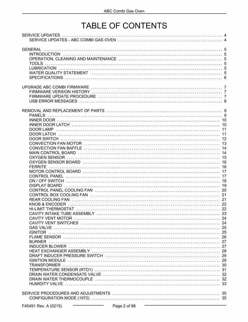
NOTE: This step can only be accomplished if maincontrol board is still operational.
NOTE: Oven hour counter (P18), water countervalues (P19, P20), and error log will start new, withreplacement main control board.
Disconnect theelectrical power to the machine andfollow lockout / tagout procedures.
2. Remove Right Panel.
3. Remove electrical connections from main controlboard and oxygen sensor board.
4. Remove main control board.
Fig. 23
NOTE: Squeeze nylon standoffs to release board.
5. Remove OXYGEN SENSOR BOARD from maincontrol board.
Installation of Replacement Control Board
1. Install OXYGEN SENSOR BOARD ontoreplacement main control board.
NOTE: Oxygen sensor board is easier to install ontomain control board before installing main controlboard.
2. Line up holes on new main control board withnylon standoffs (x10).
3. Press board onto standoffs.
4. Follow diagram Main Control BoardConnections to rewire replacement board.
5. Configure board to customer's preferredparameter settings, noted prior to removing maincontrol board. See CONFIGURATION MODE(1972) for configuration settings.
6. Refer to CALIBRATING OXYGEN SENSORBOARD.
7. Check for proper operation.
OXYGEN SENSOR
Disconnect theelectrical power to the machine andfollow lockout / tagout procedures.
Oxygen sensor is very HOT. Usecare when servicing oxygen sensor.
NOTE: Remove power from unit before replacingoxygen sensor. Having power to board when installingsensor, will cause damage oxygen sensor.
NOTE: Sensor can be damaged by water. Do not getwet.
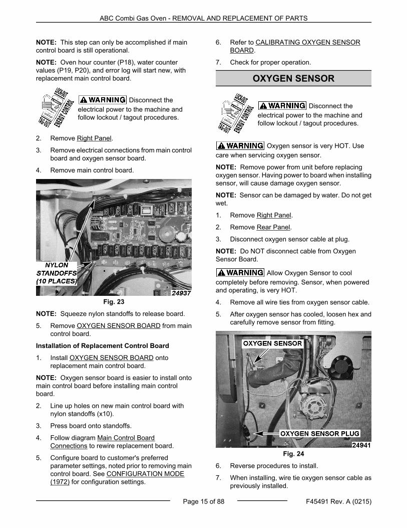
1. Remove Right Panel.
2. Remove Rear Panel.
3. Disconnect oxygen sensor cable at plug.
NOTE: Do NOT disconnect cable from OxygenSensor Board.
Allow Oxygen Sensor to coolcompletely before removing. Sensor, when poweredand operating, is very HOT.
4. Remove all wire ties from oxygen sensor cable.
5. After oxygen sensor has cooled, loosen hex andcarefully remove sensor from fitting.
Fig. 24
6. Reverse procedures to install.
7. When installing, wire tie oxygen sensor cable aspreviously installed.
ABC Combi Gas Oven - REMOVAL AND REPLACEMENT OF PARTS
Page 15 of 88 F45491 Rev. A (0215)
Oxygen Sensor cable can not lay on thebottom of the oven.
Oxygen Sensor cables are sensitive toelectrical noise and must be routed away from otherwires.
8. Power unit on.
9. CALIBRATING OXYGEN SENSOR BOARD.
10. Check for proper operation.
OXYGEN SENSOR BOARD
Disconnect theelectrical power to the machine andfollow lockout / tagout procedures.
Certain components in this system aresubject to damage by electrostatic discharge duringfield repairs. A field service grounding kit is availableto prevent damage. The field service kit must be usedanytime the control board is handled.
1. Remove Right Panel.
2. Remove electrical connections from oxygensensor board.
NOTE: Note locations of wires.
3. Remove oxygen sensor board screws. Retainscrews for installation of replacement oxygensensor board.
Fig. 25
Oxygen sensor board must be installedwhile unit is unplugged. Failure to Do so will causepermanent damage to oxygen sensor board.
Installation of Oxygen Sensor Board.
1. Verify oxygen sensor board holes line up with themain control board holes.
NOTE: Connect 9 pin connection on back side ofoxygen board header to 9 pins located on main controlboard oxygen board header.
Fig. 26
2. Secure using screws from replaced board.
3. Power on unit.
4. CALIBRATING OXYGEN SENSOR BOARD.
5. Check for proper operation.
FERRITE
Disconnect theelectrical power to the machine andfollow lockout / tagout procedures.
1. Remove Right Panel.
2. Lift ferrite clip with flat screw driver (2 places).
Fig. 27
3. Reverse procedures to install.
ABC Combi Gas Oven - REMOVAL AND REPLACEMENT OF PARTS
F45491 Rev. A (0215) Page 16 of 88
NOTE: When installing, place ferrite approximately 3inches from oxygen sensor board.
NOTE: Loop ferrite wires around the ferrite to keepferrite in place.
Fig. 28
MOTOR CONTROL BOARD
Disconnect theelectrical power to the machine andfollow lockout / tagout procedures.
Certain components in this system aresubject to damage by electrostatic discharge duringfield repairs. A field service grounding kit is availableto prevent damage. The field service kit must be usedanytime the control board is handled.
1. Remove Right Panel.
2. Document wire locations.
3. Remove electrical connections from board.
4. Remove motor control board. (4 Nylon screws)
Fig. 29
5. Replace motor control board.
6. Reverse procedure to install.
7. Check for proper operation.
CONTROL PANEL
Disconnect theelectrical power to the machine andfollow lockout / tagout procedures.
Certain components in this system aresubject to damage by electrostatic discharge duringfield repairs. A field service grounding kit is availableto prevent damage. The field service kit must be usedanytime the control board is handled.
Control Panel
1. Remove Right Panel.
2. Disconnect multi pin connectors.
3. Disconnect control board ribbon cable.
ABC Combi Gas Oven - REMOVAL AND REPLACEMENT OF PARTS
Page 17 of 88 F45491 Rev. A (0215)
Fig. 30
4. Remove ribbon cable wire tie.
NOTE: Replace wire tie on install.
Fig. 31
5. Remove 6 recessed control panel screws.
Fig. 32
6. Lift control panel up off hooks.
NOTE: Carefully pull connector and ribbon cablethrough hole when removing control panel.
7. Place control panel on a clean, flat surface.
8. Place in a secure location.
Do NOT place control panel flat on knobs.Doing so will cause damage to encoders.
Fig. 33
9. Reverse procedures to install.
NOTE: The motor control board ribbon cable will fit inJ1 as well as J8, make sure it gets plugged in to J1 onMain board.
10. Verify proper operation.
ON / OFF SWITCH
Disconnect theelectrical power to the machine andfollow lockout / tagout procedures.
On / Off Switch
1. Remove CONTROL PANEL from unit.
2. Place control panel in a secure location on aclean, flat surface.
NOTE: Do NOT place control panel flat on knobs.Doing so will cause damage to encoders.
Fig. 34
3. Remove screws from back of control base panel.
ABC Combi Gas Oven - REMOVAL AND REPLACEMENT OF PARTS
F45491 Rev. A (0215) Page 18 of 88
Fig. 35
NOTE: Use care when removing back of control panelcover. Wires are attached.
Certain components in this system aresubject to damage by electrostatic discharge duringfield repairs. A field service grounding kit is availableto prevent damage. The field service kit must be usedanytime the control board is handled.
4. Unplug wires from back of On/Off switch
Fig. 36
5. Using a pair of channel locks, squeeze in thesides and press the switch out the front of thepanel.
6. Reverse procedures to install.
7. Check for proper operation.
DISPLAY BOARD
Disconnect theelectrical power to the machine andfollow lockout / tagout procedures.
Certain components in this system aresubject to damage by electrostatic discharge duringfield repairs. A field service grounding kit is availableto prevent damage. The field service kit must be usedanytime the control board is handled.
Display Board
1. Remove CONTROL PANEL from unit.
2. Place control panel in a secure location on aclean, flat surface.
NOTE: Do NOT place control panel flat on knobs.Doing so will cause damage to encoders.
Fig. 37
3. Remove screws from back of control base panel.
Fig. 38
NOTE: Use care when removing back of control panelcover. Wires are attached.
ABC Combi Gas Oven - REMOVAL AND REPLACEMENT OF PARTS
Page 19 of 88 F45491 Rev. A (0215)
Certain components in this system aresubject to damage by electrostatic discharge duringfield repairs. A field service grounding kit is availableto prevent damage. The field service kit must be usedanytime the control board is handled.
4. Remove display board ribbon cable.
5. Remove encoder ribbon cables.
6. Remove display board nuts.
Fig. 39
7. On the new display board, make sure that jumperJ5 on the back of the display board is installedand on the correct two pins. (The two closest tothe edge of the board.)
Fig. 40
8. Reverse procedures to install.
9. Check for proper operation.
CONTROL PANEL COOLING FAN
Disconnect theelectrical power to the machine andfollow lockout / tagout procedures.
Certain components in this system aresubject to damage by electrostatic discharge duringfield repairs. A field service grounding kit is availableto prevent damage. The field service kit must be usedanytime the control board is handled.
Display Board Fan
1. Remove CONTROL PANEL from unit.
2. Place control panel in a secure location.
NOTE: Do NOT place control panel flat on knobs.Doing so will cause damage to encoders.
Fig. 41
3. Remove screws from back of control base panel.
Fig. 42
4. Disconnect cooling fan wire connection.
5. Remove cooling fan nuts.
ABC Combi Gas Oven - REMOVAL AND REPLACEMENT OF PARTS
F45491 Rev. A (0215) Page 20 of 88
Fig. 43
6. When installing fan, verify arrows are facing thecorrect direction.
NOTE: Air to exhaust out of control panel.
Fig. 44
7. Reverse procedure to install.
8. Check for proper operation.
CONTROL BOX COOLING FAN
Disconnect theelectrical power to the machine andfollow lockout / tagout procedures.
1. Remove Right Panel.
2. Unplug two wires going to fan.
3. Remove two screws securing fan to frame.
4. Reverse procedure to install.
5. Check for proper air flow.
Fig. 45
REAR COOLING FAN
Disconnect theelectrical power to the machine andfollow lockout / tagout procedures.
1. Remove Rear Panel.
2. Remove two wires going to fan.
3. Remove nuts securing fan to frame.
4. Reverse procedure to install.
5. Check for proper air flow.
Fig. 46
ABC Combi Gas Oven - REMOVAL AND REPLACEMENT OF PARTS
Page 21 of 88 F45491 Rev. A (0215)
KNOB & ENCODER
Disconnect theelectrical power to the machine andfollow lockout / tagout procedures.
Certain components in this system aresubject to damage by electrostatic discharge duringfield repairs. A field service grounding kit is availableto prevent damage. The field service kit must be usedanytime the control board is handled.
Control Knob & Encoder
1. Remove CONTROL PANEL.
2. Place control panel in a secure location.
NOTE: Do NOT place control panel flat on knobs.Doing so will cause damage to encoders.
Fig. 47
3. Remove control base panel.
4. Disconnect encoder ribbon cables.
Fig. 48
5. Loosen set screw in tapped hole on knob.
Fig. 49
6. Remove encoder nut to remove encoder.
7. Reverse procedures to install.
NOTE: Tapped hole needs to be aligned with flat partof encoder.
8. Check for proper operation.
HI-LIMIT THERMOSTAT
Disconnect theelectrical power to the machine andfollow lockout / tagout procedures.
1. Remove hi-limit thermostat screws.
Fig. 50
NOTE: Gas Unit shown.
2. Remove hi-limit thermostat probe.
NOTE: Hi-limit thermostat probe is located on top ofunit, under insulation.
ABC Combi Gas Oven - REMOVAL AND REPLACEMENT OF PARTS
F45491 Rev. A (0215) Page 22 of 88
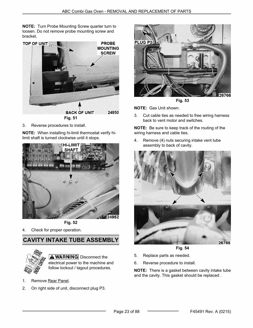
NOTE: Turn Probe Mounting Screw quarter turn toloosen. Do not remove probe mounting screw andbracket.
Fig. 51
3. Reverse procedures to install.
NOTE: When installing hi-limit thermostat verify hi-limit shaft is turned clockwise until it stops.
Fig. 52
4. Check for proper operation.
CAVITY INTAKE TUBE ASSEMBLY
Disconnect theelectrical power to the machine andfollow lockout / tagout procedures.
1. Remove Rear Panel.
2. On right side of unit, disconnect plug P3.
Fig. 53
NOTE: Gas Unit shown.
3. Cut cable ties as needed to free wiring harnessback to vent motor and switches.
NOTE: Be sure to keep track of the routing of thewiring harness and cable ties.
4. Remove (4) nuts securing intake vent tubeassembly to back of cavity.
Fig. 54
5. Replace parts as needed.
6. Reverse procedure to install.
NOTE: There is a gasket between cavity intake tubeand the cavity. This gasket should be replaced .
ABC Combi Gas Oven - REMOVAL AND REPLACEMENT OF PARTS
Page 23 of 88 F45491 Rev. A (0215)
CAVITY VENT MOTOR
Disconnect theelectrical power to the machine andfollow lockout / tagout procedures.
1. Remove Rear Panel
2. Remove CAVITY INTAKE TUBE ASSEMBLY.
3. Rotate damper camshaft until set screw faces therear of the cavity intake tube assembly.
Fig. 55
4. Loosen set screw.
5. Remove two screws securing the vent motor tothe frame.
6. Pull motor free from assembly.
7. Insert blade of small screwdriver into wire nuts torelease motor wires.
Fig. 56
NOTE: A small straight blade screwdriver (Jewelerscrewdriver) is needed.
NOTE: If a small screwdriver is not available, cuttingthe wires and using a standard wire nut is acceptable.
8. Reverse procedure to install.
NOTE: When inserting the new motor, insure the flatside of the motor shaft faces the set screw.
9. Check CAVITY VENT SWITCH TEST ANDADJUSTMENT.
10. Check for proper operation.
CAVITY VENT SWITCHES
Disconnect theelectrical power to the machine andfollow lockout / tagout procedures.
1. Remove Rear Panel.
2. Remove wires going to cavity vent switches.
Fig. 57
3. Remove bottom screw securing switches toframe.
ABC Combi Gas Oven - REMOVAL AND REPLACEMENT OF PARTS
F45491 Rev. A (0215) Page 24 of 88
Fig. 58
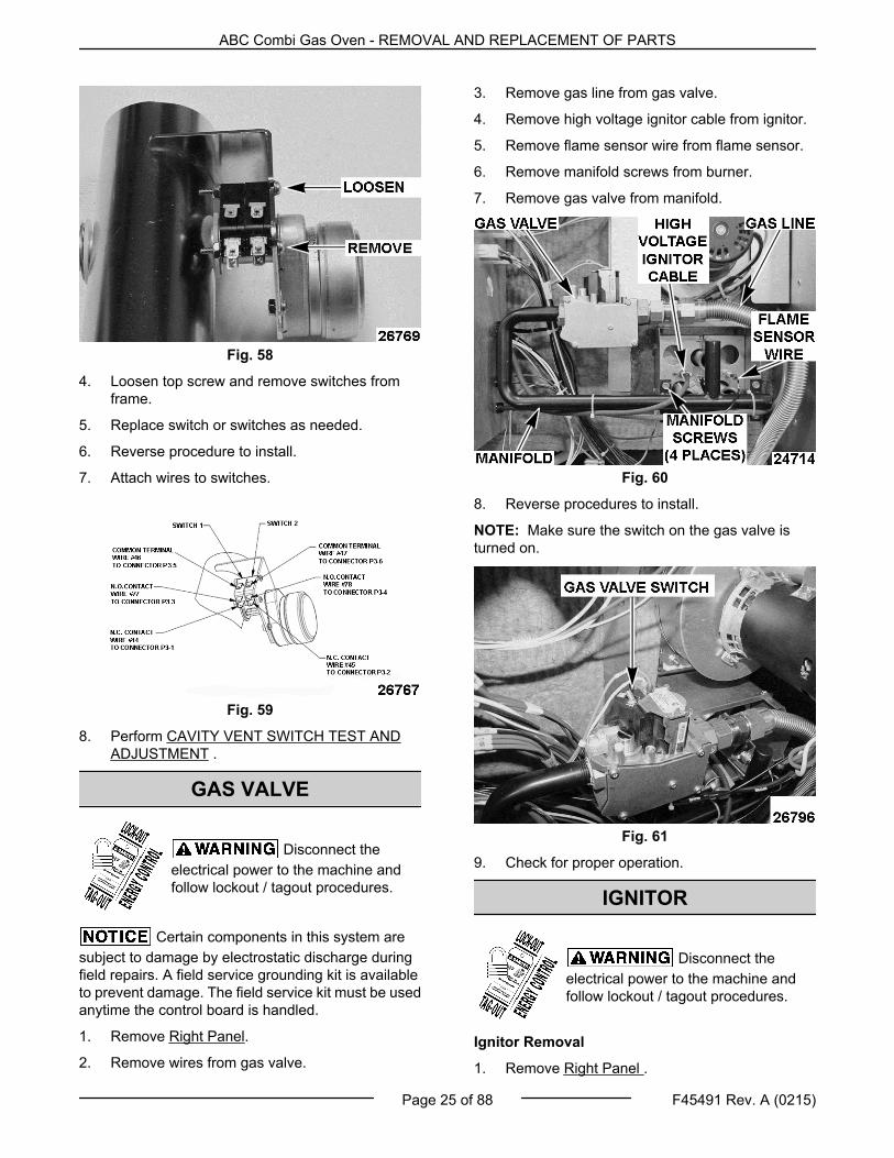
4. Loosen top screw and remove switches fromframe.
5. Replace switch or switches as needed.
6. Reverse procedure to install.
7. Attach wires to switches.
Fig. 59
8. Perform CAVITY VENT SWITCH TEST ANDADJUSTMENT .
GAS VALVE
Disconnect theelectrical power to the machine andfollow lockout / tagout procedures.
Certain components in this system aresubject to damage by electrostatic discharge duringfield repairs. A field service grounding kit is availableto prevent damage. The field service kit must be usedanytime the control board is handled.
1. Remove Right Panel.
2. Remove wires from gas valve.
3. Remove gas line from gas valve.
4. Remove high voltage ignitor cable from ignitor.
5. Remove flame sensor wire from flame sensor.
6. Remove manifold screws from burner.
7. Remove gas valve from manifold.
Fig. 60
8. Reverse procedures to install.
NOTE: Make sure the switch on the gas valve isturned on.
Fig. 61
9. Check for proper operation.
IGNITOR
Disconnect theelectrical power to the machine andfollow lockout / tagout procedures.
Ignitor Removal
1. Remove Right Panel .
ABC Combi Gas Oven - REMOVAL AND REPLACEMENT OF PARTS
Page 25 of 88 F45491 Rev. A (0215)
2. Disconnect high voltage cable from ignitor.
Fig. 62
3. Remove ignitor screw.
4. Pull ignitor to remove.
5. Reverse procedures to install.
NOTE: Make sure to keep the high voltage cablerouted separately from flame sensor cable (wire 206)and the ground wire (wire 205).
Fig. 63
6. Check for proper operation.
FLAME SENSOR
Disconnect theelectrical power to the machine andfollow lockout / tagout procedures.
NOTE: Make sure to keep high voltage cable routedseparately from flame sensor cable (wire 206) and theground wire (wire 205).
ABC Combi Gas Oven - REMOVAL AND REPLACEMENT OF PARTS
F45491 Rev. A (0215) Page 26 of 88
Fig. 65
6. Check for proper operation.
BURNER
Disconnect theelectrical power to the machine andfollow lockout / tagout procedures.
1. Remove manifold screws.
2. Gas valve, gas line, and manifold can be placeaside.
NOTE: It is not necessary to remove gas line. Gasline can be used to hold gas valve and manifoldassembly.
Fig. 66
3. Remove burner ground screw from burner.
4. Remove burner screws to remove burner.
5. Remove burner seal.
NOTE: A scraper can be used to remove burner seal.
Fig. 67
6. Reverse procedures to install.
7. Check for proper operation.
INDUCER BLOWER
Disconnect theelectrical power to the machine andfollow lockout / tagout procedures.
1. Remove Right Panel.
2. Remove Rear Panel .
3. Disconnect inducer blower wires.
INDUCERBLOWER WIRE HARNESS
BLACK 211 (Black)
WHITE 213 (White)
RED 212 (Red)
4. Remove motor shroud screws.
5. Lift up and towards front of unit to remove.
ABC Combi Gas Oven - REMOVAL AND REPLACEMENT OF PARTS
Page 27 of 88 F45491 Rev. A (0215)
Fig. 68
6. Remove air pressure hose.
7. Remove gas flue screws.
8. Remove gas flue from rear of unit.
9. Lift up and back to remove.
10. Remove inducer blower screws.
Fig. 69
11. Pull to remove inducer blower.
12. Remove any excess inducer blower seal beforereplacing seal.
13. Reverse procedures to install.
14. Check for proper operation.
HEAT EXCHANGER ASSEMBLY
Disconnect theelectrical power to the machine andfollow lockout / tagout procedures.
1. Remove Right Panel.
2. Remove Rear Panel.
3. Remove INDUCER BLOWER.
4. Remove insulation above inducer blower.
5. Remove insulation to left of inducer blower.
NOTE: Retain insulation to reinstall after repairs.
6. Insert 2x4 board between heat exchanger andbottom of cavity.
Fig. 70
7. Support gas valve / burner assembly with a blockof wood.
Fig. 71
8. Remove mounting plate nuts.
9. Remove burner assembly nuts.
ABC Combi Gas Oven - REMOVAL AND REPLACEMENT OF PARTS
F45491 Rev. A (0215) Page 28 of 88
Fig. 72
10. Pull to remove heat exchanger.
NOTE: Check heat exchanger gasket for propersealing.
11. Replace heat exchanger gasket.
12. Reverse procedure to install.
13. Check for proper operation.
DRAFT INDUCER PRESSURESWITCH
Disconnect theelectrical power to the machine andfollow lockout / tagout procedures.
1. Remove Right Panel.
2. Remove leads from pressure switch.
Fig. 73
3. Remove tube from pressure switch.
4. Remove screws securing pressure switch.
5. Reverse procedure to install.
IGNITION MODULE
Disconnect theelectrical power to the machine andfollow lockout / tagout procedures.
1. Remove Right Panel.
2. Remove high voltage cable.
Fig. 74
3. Remove wires.
IgnitionModule Description Wire
NumberS1 Remote Flame Sensor 206
GND System Ground 205
V2 Valve Ground 207
24VAC 24 VAC Supply 209
L1 120 VAC Input (hot) 203
IND Inducer Blower (output) 204
NC Alarm (normally closedcontact) 225
V1 Valve Power (Output) 208
PSW Pressure Switch Input 201
TH / W Thermostat Input 200
FC+
FC-Flame Current Test
Pins None
4. Remove ignition module screws.
5. Reverse procedure to install.
ABC Combi Gas Oven - REMOVAL AND REPLACEMENT OF PARTS
Page 29 of 88 F45491 Rev. A (0215)
Fig. 75
NOTE: Make sure to keep the high voltage cablerouted separately from flame sensor cable (wire 206)and the ground wire (wire 205).
Fig. 76
6. Check for proper operation.
TRANSFORMER
Disconnect theelectrical power to the machine andfollow lockout / tagout procedures.
1. Remove Right Panel.
2. Disconnect Plugs 7 and 8 going to Transformer.
Fig. 77
3. Remove two nuts on the left hand side oftransformer bracket.
Fig. 78
4. Remove nut on the right hand side of transformerbracket.
ABC Combi Gas Oven - REMOVAL AND REPLACEMENT OF PARTS
F45491 Rev. A (0215) Page 30 of 88
Fig. 79
CAUTION Transformer weighs 12.5 pounds andhas a strong magnetic pull to the frame of oven.
5. Slide transformer off of studs and down to thebottom of the oven.
Fig. 80
6. Remove transformer and bracket from oven.
7. Remove nut and washer securing transformer tobracket.
Fig. 81
8. Replace transformer.
9. Reverse procedure to install.
TEMPERATURE SENSOR (RTD1)
Disconnect theelectrical power to the machine andfollow lockout / tagout procedures.
1. Remove Right Panel.
2. Remove Rear Panel.
3. Remove wire ties attaching wires going totemperature sensor to the oxygen sensor cable.
Fig. 82
4. Remove black wire from TB2-3 and red wire fromTB2-4.
NOTE: Insert small screwdriver in square next to thewire to release the wire from terminal block.
ABC Combi Gas Oven - REMOVAL AND REPLACEMENT OF PARTS
Page 31 of 88 F45491 Rev. A (0215)
Fig. 83
5. Push back installation to get access to the nutssecuring the probe.
Fig. 84
6. Remove the two nuts.
7. Remove temperature sensor RTD1 from unit.
8. Install new probe.
9. Reverse procedure to install.
NOTE: Attach wire ties in same spots as before.
DRAIN WATER CONDENSATEVALVE
Disconnect theelectrical power to the machine andfollow lockout / tagout procedures.
1. Remove Right Panel.
2. Remove Rear Panel.
3. Remove two screws securing valve to utilitypanel.
Fig. 85
NOTE: Gas Unit shown.
4. Remove two wires going to valve.
5. Loosen hose clamp and pull valve free of hose.
Fig. 86
6. Replace valve.
7. Reverse procedure to install.
DRAIN WATER THERMOCOUPLE
Disconnect theelectrical power to the machine andfollow lockout / tagout procedures.
1. Remove Right Panel.
2. Loosen screws for terminal TC1 and removewires.
ABC Combi Gas Oven - REMOVAL AND REPLACEMENT OF PARTS
F45491 Rev. A (0215) Page 32 of 88
Fig. 87
3. Cut cable ties securing wires going to drain waterthermocouple.
4. Loosen nut securing the thermocouple.
Fig. 88
5. Pull thermocouple from housing.
Fig. 89
6. Replace thermocouple.
7. Reverse procedure to install.
HUMIDITY VALVE
Disconnect theelectrical power to the machine andfollow lockout / tagout procedures.
1. Remove Right Panel.
2. Remove Rear Panel.
3. Remove two screws securing humidity valve toutility panel.
Fig. 90
NOTE: Gas Unit shown.
NOTE: The humidity valve is a double valve.
4. Remove two wires going to drain watercondensate valve.
NOTE: This makes it easier to pull the humidity valveout from behind the utility panel.
5. Remove the four wires going to humidity valve.
NOTE: Make sure to note which wire goes to whichterminal.
ABC Combi Gas Oven - REMOVAL AND REPLACEMENT OF PARTS
Page 33 of 88 F45491 Rev. A (0215)
Fig. 91
6. Loosen the two hose clamps securing the valveand free the valve from the two hoses.
Fig. 92
7. Replace valve.
8. Reverse procedure to install.
ABC Combi Gas Oven - REMOVAL AND REPLACEMENT OF PARTS
F45491 Rev. A (0215) Page 34 of 88
SERVICE PROCEDURES AND ADJUSTMENTS
Certain procedures in this section require electrical test or measurements whilepower is applied to the machine. Exercise extreme caution at all times and follow Arc Flashprocedures. If test points are not easily accessible, disconnect power and follow Lockout/Tagoutprocedures, attach test equipment and reapply power to test.
CONFIGURATION MODE (1972)
Log Into Configuration Mode 1972 1. Check with customer to verify settings have not been altered from factory settings.
2. Turn unit on.
NOTE: Oven must have no temp set to enter configuration.
3. Turn Timer knob counterclockwise until Timer display shows "set".
4. Turn Humidity knob counterclockwise until Humidity display shows "PAS".
A. Timer display will show "2000".
5. Turn Timer display counterclockwise to 1972.
A. Timer display will flash "1972".
B. Timer and Humidity display will flash twice.
C. Humidity display changes from "PAS" to "CFg" when logging into Configuration Mode.
D. Temperature Display will go to P0, which is the first configuration setting. To review / change Configuration Mode 1972settings
1. Turn the Temperature knob clockwise one step at a time, to go to the next configuration setting.
NOTE: Currently addresses P21, P22, P29, P30, P31 and P32 are blank.
2. Presently P35 is the last address, the counter will continue to go higher, but the Time display and the Humiditydisplay will be blank.
3. Turn the Humidity Knob to change the values as needed.
4. The following chart list the options for each address.
Temp.
Display
("---")Description
Time Display
("----")
Humidity Display
("---")
P0Current firmware code revision (Month,day, year). Time and Humidity showexample.
0225
(Month: 02, Date: 25)
14
(Year: 2014)
Letter after number = Revwithin date
P1 Set temperature to Fahrenheit or Celsius. UnIt F or C
ABC Combi Gas Oven - SERVICE PROCEDURES AND ADJUSTMENTS
Page 35 of 88 F45491 Rev. A (0215)
Temp.Display
("---")Description
Time Display
("----")
Humidity Display
("---")
P2Temperature knob increments.
Temperature increment can be adjustedby 1, 5, or 10 degrees.
tInC 1, 5, 10, 25
P3Humidity knob increments.
Humidity can be adjusted by 1 or 10percent increments.
HInC 1 and 10
P4
Custom Operator Interface
Turn Hum knob betweenFactory (FACt) and Custom
(CUSt)
Factory Default UI Setting FACt
Custom UI Setting CUSt
NOTE: Operator can flip between P4 FACt and P4 CUSt. Customsettings will be remembered.
NOTE: Only when P4 is set to custom can settings in P5 and P6 beconfigured.
P5
Define Temperature Selection in UI
NOTE: Only when P4 is set to custom cansettings in P5 and P6 be configured.
FACt
CUSt
(Indicates customersettings are currentlyloaded.)
SEt
Turn knob to edit customsettings.
ALL
oN
TIP: Select “ALL on” to begincustomizing if minimalchanges needed to FACtsettings.
ALL
oFF
TIP: Select “ALL oFF” if youwant to start customizingfrom scratch.
80 (min)
.
.
.
... 482 (max)
Turn Timer knob throughtemperature choices.
oFF / on
Hum knob can be toggled tochange individualtemperature on or off.
ABC Combi Gas Oven - SERVICE PROCEDURES AND ADJUSTMENTS
F45491 Rev. A (0215) Page 36 of 88
Temp.Display
("---")Description
Time Display
("----")
Humidity Display
("---")
P6
Define Humidity Selection in UI
NOTE: Only when P4 is set to custom cansettings in P5 and P6 be configured.
FACt
80 (F)
.
.
.
482(F)
Turn Timer knob throughtemperature choices.
90 (% humidity)
.
.
.
0 (%)
Hum knob can be used tochange humidity mapping toselected temperature.
NOTE: The following is an example of customizing the P4 through P6 settings.
P4P4 set to CUSt Example
1. Toggle Hum knob to select CUStsettings.
CUSt
P52. Turn Temperature knob to P5.
3. Toggle Hum knob oFF.ALL oFF
4. Scroll timer knob to temperature of 212.
5. Toggle humidity knob to on.212(F) on
6. Scroll timer knob to 325.
7. Toggle humidity knob to on.325(F) on
P6
8. Turn Temperature knob to P6.
9. Scroll timer knob to 325.
10. Toggle knob to 0%
212(F)
325(F)
100(%)
0(%)
11. At completion, user interface is customized so user can only select 212F @ 100% or 325F @0%
End of example.
P7 Allows users to manual adjust humiditysettings during operation. HAdJ on / oFF
P8
Oven Buzzer
ON - Buzzer stops after 5 seconds.
OFF - Buzzer turns on until door is openedor timer is turned off.
b 5 on / oFF
P9
Door Lights
ON - Door lights flash at end of timercountdown.
OFF - Door lights do not flash at end ofcountdown.
FLSH on / oFF
ABC Combi Gas Oven - SERVICE PROCEDURES AND ADJUSTMENTS
Page 37 of 88 F45491 Rev. A (0215)
Temp.Display
("---")Description
Time Display
("----")
Humidity Display
("---")
P10
Batch Timer.
Timer recalls last operated value whendoor is open and closed after buzzer.User does not need to reset timer.
For example, User removes a batch offries from oven and puts in a second batchof fries.
trCL on / oFF
P11Clean reminder.
"CLn good bYE" shown when on/offswitch is toggled off.
CLn on / oFF
P12 Convection Fan Speed. (not adjustable) FSPd 7
P13 Convection Fan Breaking Speed. (notadjustable) F br 5
P14Reversing fan timing.
Number of minutes cavity fan turns beforebreaking and turning in opposite direction.
FrEU Off, 1 , 2, 3, 4, 5
P15
Define maximum temperature knobsetting in UI.
Maximum temperature that can be set byuser. Minimum setting limited by P16.
t_HI 80 thru 450 increments of 10.
P16
Define minimum temperature knobsetting in UI.
Minimum temperature that can be set byuser. Maximum setting limited by P15.
NOTE: Must be less than P15.
NOTE: Settings at P15 and P16 are onlyin effect if P4 is set to FACt.
t_Lo 80 thru 450 increments of 10.
P17
Cavity Automatic Steam Reduction:Reduces the cavity's steam build upbefore end of timed cook. Vent intake isopened "selected" seconds before end oftimer countdown.
NOTE: Steam reduction is not engagedmid-cook or during a "non-timed" cookwhen door opened.
Example: P17 = 30 seconds (default). Asthe cook time counts down, the ventopens allowing the steam to dissipate.
AUto oFF, 30, 60, 90
ABC Combi Gas Oven - SERVICE PROCEDURES AND ADJUSTMENTS
F45491 Rev. A (0215) Page 38 of 88
Temp.Display
("---")Description
Time Display
("----")
Humidity Display
("---")
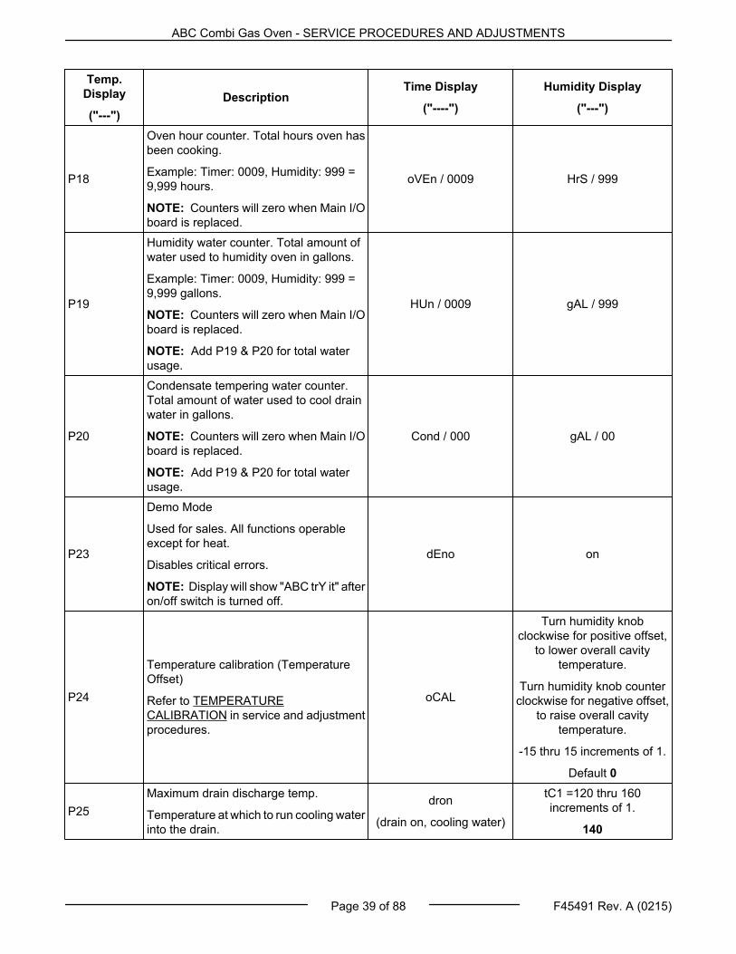
P18
Oven hour counter. Total hours oven hasbeen cooking.
Example: Timer: 0009, Humidity: 999 =9,999 hours.
NOTE: Counters will zero when Main I/Oboard is replaced.
oVEn / 0009 HrS / 999
P19
Humidity water counter. Total amount ofwater used to humidity oven in gallons.
NOTE: Counters will zero when Main I/Oboard is replaced.
NOTE: Add P19 & P20 for total waterusage.
HUn / 0009 gAL / 999
P20
Condensate tempering water counter.Total amount of water used to cool drainwater in gallons.
NOTE: Counters will zero when Main I/Oboard is replaced.
NOTE: Add P19 & P20 for total waterusage.
Cond / 000 gAL / 00
P23
Demo Mode
Used for sales. All functions operableexcept for heat.
Disables critical errors.
NOTE: Display will show "ABC trY it" afteron/off switch is turned off.
dEno on
P24
Temperature calibration (TemperatureOffset)
Refer to TEMPERATURECALIBRATION in service and adjustmentprocedures.
oCAL
Turn humidity knobclockwise for positive offset,
to lower overall cavitytemperature.
Turn humidity knob counterclockwise for negative offset,
to raise overall cavitytemperature.
-15 thru 15 increments of 1.
Default 0
P25Maximum drain discharge temp.
Temperature at which to run cooling waterinto the drain.
dron
(drain on, cooling water)
tC1 =120 thru 160increments of 1.
140
ABC Combi Gas Oven - SERVICE PROCEDURES AND ADJUSTMENTS
Page 39 of 88 F45491 Rev. A (0215)
Temp.Display
("---")Description
Time Display
("----")
Humidity Display
("---")
P26
Target maximum drain discharge temp.
Temperature at which to stop coolingwater into the drain.
NOTE: P25 and P26 are dependant oneach other. The system will not allowthem to be set closer than 5°.
droF
(drain off, cooling water)
115 thru 155 increments of 1.
tC1 = 130
P27
Condensate tempering probe.
Enabled: Tempering of drain water basedon condensate probetemperature(Energy efficient). See P25 &P26.
Disabled: Continuous time basedtempering when in steam mode. (Lessenergy efficient.)
StPr EnA / d15
P28
Additional Humidity knob operatorinterface.
Enabled: Customer has option to turnhumidity knob below 0, to a "---" setpoint.In this mode, vent is forced closed and nohumidity water valve operation.
Disabled: Humidity knob choices are setbetween 0 to 100%.
AStn EnA / d15
P32 Oxygen board calibrate / zero ZEro
no
Turning knob to "yes"indicates a multi step
procedure.
P33
Oxygen Sensor Data
Shown in % of Absolute Humidity. Thisvalue will not match the % RelativeHumidity value shown on User Interfaceat oven cavity temperatures < 212°F.
ONLY USED WHEN CALIBRATINGOXYGEN SENSOR. (Refer toCALIBRATING OXYGEN SENSORBOARD.)
51
NOTE: Combine the twonumbers to get 51.2%.
.2
ABC Combi Gas Oven - SERVICE PROCEDURES AND ADJUSTMENTS
C. Humidity display changes from "PAS" to"CFg" when logging into ConfigurationMode.
Oxygen Sensor Board Check (P33)
1. Turn Temperature knob clockwise to "P33".
• Timer display should read between 0 and24.
• Humidity display should read between .00and .99
NOTE: If timer displays "----" when viewing P33,oxygen sensor is warming. Wait 3 minutes. Whenready, Timer / Humidity display will change to anumeric value.
Calibration of Oxygen Sensor Board (P32)
1. Turn Temperature knob counterclockwise toP32.
• Timer displays "ZEro".
• Humidity displays "no".
2. With cavity door still open, turn Humidity knobclockwise to "yes".
NOTE: Timer display will toggle between "OPEN" and"DOOR", and beeps if door is closed.
ABC Combi Gas Oven - SERVICE PROCEDURES AND ADJUSTMENTS
Page 41 of 88 F45491 Rev. A (0215)
• Convection fan turns on.
NOTE: Oven cavity temperature must be below100°F.
4. If temperature not less than 100°F / 38°C, timerdisplay toggles cool/xxx°F (xxx°F / xxx°C=current temperature), until temperature is below100°F / 38°C.
5. Timer display flashes "---" when conditions areready for calibration.
NOTE: If conditions are not met: ( "P33" less than orequal to 24, cavity temperature less than 100°F /38°C, with door open, and convection fan up tospeed.) Time knob will not enter 0000 and beep.
6. Turn Timer knob clockwise to "0000", one digit ata time.
7. Timer displays "donE" and Humidity displays"yes" when complete.
8. Convection fan turns off.
NOTE: To exit out of calibrating oxygen sensor boardbefore calibrating, turn Humidity knob to "no" or turnTemperature knob to exit.
Oxygen Sensor Board Check
1. Turn Temperature knob clockwise to "P33".
• Timer display should read between 0 and 2.
• Humidity display should read between .00and .99
NOTE: This value should be near 0%. For example,timer = 2, humidity = .99, represents 2.99%.
Exit out of Configuration Mode 1972
1. Turn Temperature knob counterclockwise until"---" displayed.
GAS VALVE PRESSURE CHECKAND ADJUSTMENT
Disconnect theelectrical power to the machine andfollow lockout / tagout procedures.There may be multiple circuits. Be sureall circuits are disconnected.
Shut off the gas before servicing theunit.
STATIC LINE PRESSURE
1. Remove Right Panel.
Fig. 93
2. Manifold Pressure
A. Open Inlet pressure Tap by turning screw 1to 2 turns CCW.
B. Attach manometer hose to Inlet pressureTap.
Fig. 94
C. Reconnect power and turn gas supply on.
D. If static line pressure exceeds 14" W.C. (½psig) the customer must supply and install apressure reducing valve to reduce thepressure below the maximum allowable forthe valve.
E. Close Inlet pressure Tap by turning screwCW. until tight.
ABC Combi Gas Oven - SERVICE PROCEDURES AND ADJUSTMENTS
F45491 Rev. A (0215) Page 42 of 88
Disconnect theelectrical power to the machine andfollow lockout / tagout procedures.There may be multiple circuits. Be sureall circuits are disconnected.
Shut off the gas before servicing theunit.
Manifold Pressure
1. Open Outlet pressure Tap by turning screw 1 to2 turns CCW.
2. Remove the pressure regulator adjustment capfrom the main gas valve to access the adjustmentscrew.
3. Attach manometer hose to Outlet pressure Tap
Fig. 95
4. Reconnect power and turn gas supply on.
5. Set Temperature knob to call for heat.
NOTE: Accurate gas pressure adjustment can onlybe made with the burner on.
NOTE: Turn adjustment screw clockwise to increasethe pressure. Turn adjustment screwcounterclockwise to decrease pressure.
6. Set Manifold pressure to 3.5" W.C.
NOTE: Always replace the adjustment cap afteradjustment and securely tighten to ensure properoperation.
7. Close Outlet pressure Tap by turning screw CW.until tight.
Orifice SizesAltitudes Natural Gas L.P. Gas0 - 1999 ft. # 40 #53
Orifice SizesAltitudes Natural Gas L.P. Gas2000 - 2999 ft. # 41 # 54
3000 - 5999 ft. # 42 # 54
6000 - 7999 ft. #43 # 54
8000 - 9999 ft. # 44 # 55
Above 10,000 ft. # 45 # 55
Natural Gas L.P. Gas
Static LinePressure
Min. Max. Min. Max.
5" 14" 11" 14"
ManifoldPressure 3.5" W.C. 10" W.C.
BTU's / Hr 80,000 80,000
TEMPERATURE CALIBRATION
1. Place temperature tester probe in geometriccenter of oven cavity.
2. Program a setpoint of 350°F. Allow oventemperature to cycle 3 times.
NOTE: Oven's temperature display shows setpoint.To view actual cavity temperature as it cycles aroundsetpoint, slightly turn temperature knob clockwise onenotch or counter clockwise one notch and actual cavitytemperature will blink three times.
NOTE: Turning temperature knob more than onenotch will change temperature setpoint.
3. Record temperature tester readout for anadditional 3 cycles. It should cycle aroundsetpoint.
4. Calculate amplitude. Amplitude = (Turn Off - TurnOn). An amplitude of more than 40°F mayindicate a problem with heat source. Forexample, poor combustion, see combustionanalysis.
ABC Combi Gas Oven - SERVICE PROCEDURES AND ADJUSTMENTS
Page 43 of 88 F45491 Rev. A (0215)
5. Calculate average. Actual average = (Turn On +Turn Off ) divided by 2. Variance (between actualaverage and programmed setpoint) of greaterthan 5 degrees indicates that adjustment isneeded.
6. To adjust:
A. Enter CONFIGURATION MODE (1972),scroll temperature knob to P24. Turnhumidity knob to enter offset.
NOTE: Turn humidity knob clockwise for positiveoffset, to lower overall cavity temperature.
B. If actual average temperature is higher thanprogrammed setpoint, enter a positive offsetvalue of same amount. (For example if ovenis cycling around an actual average of 360degrees, adjust by entering an offset of+10.)
C. If the actual average temperature is lowerthan programmed setpoint, enter a negativeoffset value of the same amount. (Forexample if oven is cycling around an actualaverage of 340 degrees, adjust by enteringan offset of -10.)
1) The offset can be adjusted + or - 30degrees, but is only functional withinthe operating limits of the oven. Factorysetting is 0.
7. To save setting, exit configuration mode byturning temperature knob back to "---" (idlemode) and listen for beep.
8. To recall offset value, enter CONFIGURATIONMODE (1972), turn temperature knob to P24.Verify the value set is visible in humidity.
TEMPERATURE SENSOR (RTD1)TEST
Disconnect theelectrical power to the machine andfollow lockout / tagout procedures.
1. Remove Right Panel.
2. Remove probe lead wires from Main I/O board.
3. Test probe with an ohmmeter.
TEMPERATURE in °F RESISTANCE ±5 OHMS60 530
70 541
80 552
90 563
100 573
125 600
150 627
200 680
250 732
300 785
350 836
400 887
450 938
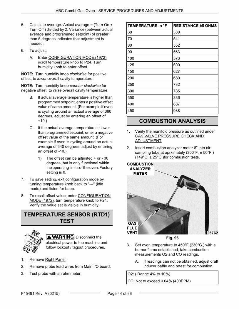
COMBUSTION ANALYSIS
1. Verify the manifold pressure as outlined underGAS VALVE PRESSURE CHECK ANDADJUSTMENT.
2. Insert combustion analyzer meter 8" into airsampling tube at aprximately (300°F. ± 50°F.)(149°C. ± 25°C.)for combustion tests.
Fig. 96
3. Set oven temperature to 450°F (230°C.) with aburner flame established, take combustionmeasurements O2 and CO readings.
A. If readings can not be obtained, adjust draftinducer baffle and retest for combustion.
O2: ( Range 4% to 10%)
CO: Not to exceed 0.04% (400PPM)
ABC Combi Gas Oven - SERVICE PROCEDURES AND ADJUSTMENTS
F45491 Rev. A (0215) Page 44 of 88
NOTE: If combustion readings still can not beobtained, contact Cooking Support.
CAVITY VENT SWITCH TEST ANDADJUSTMENT
Y10 TEST
Y10 test measures several things. Motor current,conditions of the two vent switches and the time ittakes for the two switches to indicate a change for thevent. Each time the test runs, the motor should turn ¼of a turn. A ¼ turn is what it takes to make the vent togo from fully closed to fully open, or from fully open tofully closed. It is recommended that the test be runeight times to make the motor go thru 2 full cycles. Ifno errors are encountered, the vent switches and ventmotor are operating properly.
1. Go into reference.
2. Turn the temperature knob until Y10 comes onthe display.
3. Turn the Humidity knob one step clockwise.
NOTE: The test should take about 15 seconds.
NOTE: The Timer display will go from (VEnt / CLSd,to SPin / = 5, to VEnt / oPEn) or (VEnt / oPEn, to SPin /= 5, to VEnt / CLSd)
4. If test ran successfully, turn Humidity knob onestep to run test again. Do this till test has beenrun 8 times.
If an error occurs:
1. If the Timer Display shows "Err", this means thevent switches are in an error state and needadjusted or replaced.
2. If the Timer Display shows "=Err", this means thevent motor did not draw current.
3. If after 75 seconds the vent switches do notindicate a ¼ has been made the Humidity displayshows "Err".
VENT SWITCH ADJUSTMENT
Disconnect theelectrical power to the machine andfollow lockout / tagout procedures.
1. Remove reference
2. Loosen screws securing the vent screws to theframe (by 1/4 turn) to allow the top of the switchesto be adjusted in or out.
Fig. 97
3. Remove wires 44, 45, 46, and 47 from the ventswitches
Fig. 98
4. Rotate the damper camshaft (using a pair ofchannel locks) until the indicator on the end of thecamshaft is at diagonal. (as shown in figure26786)
ABC Combi Gas Oven - SERVICE PROCEDURES AND ADJUSTMENTS
Page 45 of 88 F45491 Rev. A (0215)
Fig. 99
5. Connect a meter set to check resistance to thecommon terminal and the N.C. contact of switch1.
If reading on the meter indicates an open thenpull the top of the switch away from the camshaft.If the meter reading indicates continuity, continueto next step.
6. Press the top side of the switches towards thecamshaft until the meter indicates an open.
7. Tighten the screws securing the switches.
8. Use the meter to check the common terminal andthe N.C. contact of both switches. Both switchesat this point should read open.
9. Quick check
A. Connect a meter set to check resistance tothe common terminal and the N.C. contactof switch 1.
B. Using a pair of channel locks rotate thedamper camshaft through one revolution.
C. During one revolution of the Cam shaft, themeter should indicate continuity at twodifferent spots. These two spots should be180° from each other.
D. Repeat this check for switch 2
10. Reconnect wires to both vent switches.
11. Reattach panels.
FLAME SENSE VOLTAGE TEST(FENWAL SERIES 35-61)
Certain procedures inthis section require electrical test ormeasurements while power is appliedto the machine. Exercise extremecaution at all times and follow Arc Flashprocedures. If test points are not easilyaccessible, disconnect power andfollow Lockout/Tagout procedures,attach test equipment and reapplypower to test.
NOTE: The minimum flame voltage necessary tokeep the system from lockout is .7 Volts.
1. Connect a DC voltmeter to FC-FC+ terminals.
Fig. 100
2. Meter should read .7 volts or higher.
NOTE: If reading is below "0" volts, reverse meterleads and take another reading.
3. Disconnect power and reconnect leads forproper polarity.
4. Check for proper operation.
ABC Combi Gas Oven - SERVICE PROCEDURES AND ADJUSTMENTS
F45491 Rev. A (0215) Page 46 of 88
DRAFT INDUCER TEST
Disconnect theelectrical power to the machine andfollow lockout / tagout procedures.
1. Using two 1/4" hoses and a T connector, connectan incline manometer inline between the inducerfan and pressure switch.
Fig. 101
2. Log Into Service Mode 1963.
A. Turn unit on.
B. Turn Timer knob counterclockwise untilTimer display shows "SEt".
C. Turn Humidity knob counterclockwise untilHumidity display shows "PAS".
1) Timer display will show "2000".
D. Turn Timer display counterclockwise to1963.
1) Timer display will flash "1963".
2) Timer and Humidity display will flashtwice.
3) Humidity display changes from "PAs"to "tst" when logging into ServiceMode.
E. Use the temperature knob to advance toY16 (Blower /Air Pressure Switch test).
F. Use the Humidity Knob to start the draftinducer fan.
• The oven should pass the test.
NOTE: The pressure switch requires a minimum of 1"W.C. negative pressure to operate.
• The reading on the manometer shouldbe approx. 3 " WC of negativepressure.
3. Exit Service mode.
A. Turn Temperature knob counter clockwiseuntil "---" is displayed.
4. Use temperature knob to make the setpoint300°F.
A. With the burner ignited, the reading on themanometer should settle approx. 1.6 " WCof negative pressure.
5. Turn temperature knob counterclockwise until"---" is displayed.
6. Log Into Service Mode 1963.
A. Turn Timer knob counterclockwise untilTimer display shows "SEt".
B. Turn Humidity knob counterclockwise untilHumidity display shows "PAS".
1) Timer display will show "2000".
C. Turn Timer display counterclockwise to1963.
1) Timer display will flash "1963".
2) Timer and Humidity display will flashtwice.
3) Humidity display changes from "PAs"to "tst" when logging into ServiceMode.
D. Use the temperature knob to advance toY16 (Blower /Air Pressure Switch test).
E. Use the Humidity Knob to start the draftinducer fan.
• The oven should pass the test.
• Now with the heat exchanger being at300 °F, the reading on the manometershould be approx. 2 " WC of negativepressure.
7. Exit Service mode.
A. Turn Temperature knob counter clockwiseuntil "---" is displayed.
DOOR SWITCH ADJUSTMENT
1. In SERVICE MODE (1963), run (Y6) Door test.
NOTE: If the door test reports that the door is openwhen it is closed it may be because the door reedswitch is not lined up with the magnet in the door.
ABC Combi Gas Oven - SERVICE PROCEDURES AND ADJUSTMENTS
Page 47 of 88 F45491 Rev. A (0215)
To adjust the door reed switch:
Disconnect theelectrical power to the machine andfollow lockout / tagout procedures.
A. Remove Right Panel.
B. Remove CONTROL PANEL.
C. Loosen the two screws securing the ReedSwitch to the bracket to adjust the ReedSwitch side to side.
Fig. 102
D. Loosen the two bolts securing the ReedSwitch bracket to the control panel to adjustthe Reed Switch up and down.
ABC Combi Gas Oven - SERVICE PROCEDURES AND ADJUSTMENTS
F45491 Rev. A (0215) Page 48 of 88
ELECTRICAL OPERATION
COMPONENT FUNCTION
Main Board . . . . . . . . . . . Manages all input/output functions of oven as required for combi cook operation. Monitorsoven temp RTD probe, and outputs call for heat to ignition module. Monitors oxygensensor board and outputs to humidity valves. Monitors condensate temperingthermocouple probe and outputs to condensate valve, monitors door switch and controlscavity lights. Outputs to motor control board to control speed and direction of ConvectionFan motor. Rotates the cavity vent intake damper from open/closed using the cavity ventmotor output and two cavity vent switch inputs. Monitors on/off switch to change operatorinterface from sleep/wake mode. Enables cooling fans. Monitors the display board forcustomer input from knobs, and sends time, temperature, and humidity information todisplay board. Also monitors ignition module NC output, pressure switch NC contact forignition errors. Monitors N.O. relay contacts for high limit errors; and monitors oxygenboard and motor board for oxygen sensor and convection fan motor errors.
Display Board . . . . . . . . Processes signals from each encoder mounted to each of the three control knobs. Thensends signal to Main board. processes input signals from Main board to refresh displayswith Time Temperature and Humidity cooking information.
Low voltage portion of the board processes drive signal (amber led) and reverse signal(green led) from the Main board to control an on board reversing relay and external solidstate relay. The reversing relay contacts on the high voltage side of the board reversesvoltage phases to change the motor rotation direction; The solid state relay wired to themotor board, power the convection fan motor. The motor neutral phase is daisy chainedwith convection fan motor’s thermal fuse and F7 motor current protection fuse at the motorboard. The motor board’s current sense circuit monitors the current through the fusesand sends a low voltage signal back to the main board (viewed on the RED led) on thelow voltage side. The current sense circuit is also responsible for detecting E1 and E6errors.
Heats and controls the oxygen sensor, and reports back oven cavity humidity informationto the Main board. also receives calibration command from Main board.
Measures the amount of humidity in the oven cooking cavity and is controled by oxygensensor board.
Door Switch (SW3) . . . Magnetic reed switch it senses the presence of the magnet in the door and closes.Monitored by the main board which starts stops the cook cycle and activates the lightsbased on the state of the door switch.
Is a toggle switch that is monitored by main board to put unit from sleep to cooking idlemode. It provides 230 VAC to the following relays on the main board: cavity vent motor,high and low humidity valve, condensate tempering valve, cooling fans.
Optically coupled rotary encoder switch that is mounted behind the control knob andsends signal to display board as knob is turned in any direction.
Transformer (T1) . . . . . Transformer, with 120 VAC input. Multiple secondary voltages are as follows: 230 VACto motor board and convection fan motor, vent motor, all water solenoids and coolingfans, 12 VAC oxygen board and oxygen sensor, 12 VAC cavity lamps, 24 VAC mainboard, motor board (low voltage portion) , vent switches, door switches, high limit sensingcontacts, 24 VAC to ignition module and gas valves.
Fuse (F7) . . . . . . . . . . . . . 6.25A - motor current protection fuse. F7 protects from a malfunction of the motor board’son-board reversing relay.
Reports the position (open/closed/spin) of the cavity vent intake damper. Works inconjunction with SW1.
Humidity Valve Cavity(Low Flow) (Sol2) . . . . .
Admits water into the injection nozzle (in a slow stream) that drips onto water atomizerto vaporize the water droplets and provide steam for combi mode or cool the oventemperature.
Humidity Valve Cavity(High Flow) (Sol3) . . . .
Admits water into the injection nozzle (in a slow stream) that drips onto water atomizerto vaporize the water droplets and provide steam for combi mode or cool the oventemperature.
Monitors VACuum created by the draft inducer motor. Prevents burner ignition if avacuum of 1" W.C. is not present.
High Limit (TS1) . . . . . . Removes power from ignition module if oven overheats. The state of the high limit issensed by relay R5 which signals Vulcan Main I/o board to display error code.
Spark Electrode . . . . . . Ignites the gas.
Flame Sense Probe . . . Senses the presence of a flame.
Ignition Module . . . . . . . Controls the inducer blower and gas valve. Generates the spark for burner ignition,monitors the pressure switch and the presence of a flame and controls the No ignitionlight.
When energized, drives fan to generate draft required for proper oven operation, andexhausts combustion products out of flue.
Cold WaterCondensate (Sol1) . . . .
Admits water to p-trap on power up to seal oven cavity. And admits water ptrap to mixwith drain water to cool drain discharge water to 140°F before exiting oven.
Solid State Relay used to drive the convection fan motor. Is controlled by the motor controlboard.
Ferrite . . . . . . . . . . . . . . . . Passive electric component used to suppress high frequency noise from the oxygensensor board..
ELECTRICAL PANEL COMPONENT LOCATION
Fig. 103
ABC Combi Gas Oven - ELECTRICAL OPERATION
Page 51 of 88 F45491 Rev. A (0215)
SEQUENCE OF OPERATIONNOTE: Refer to schematic diagram for the electrical sequence of operation.
Conditions
1. Unit plugged into 120 VAC incoming powersupply and is properly grounded.
2. ON/OFF switch (SW4) off.
3. Door switch closed (SW3).
4. High limit switch (TS1) closed.
5. 120 VAC
A. 120 VAC to TB1-9C to:
1) Blower test relay’s COM contact(R4.2).
2) L1 (blower relay) on ignition module.
B. 120 VAC (Com) to TB1-8A to:
1) Inducer blower COM.
C. 120 VAC to Transformer T1 (TB1-9, TB1-8 )for correct oven voltage on primary input ofT1.
1) Transformer step up from 120 VAC to230 VAC providing voltage for ovencomponents (solenoid valves, motorboard (convection fan motor ), ventintake motor, and cooling fans.
2) Transformer steps down from 120 VACto 24 VAC on two secondaries, 24 VACand 24 VAC (IM).
a. 24 VAC (IM) providing voltage forrelay coils R4, R5, for high limitswitch, and for ignition moduleand gas valve, call for heat relays.
b. 24 VAC providing voltage for mainbd, motor bd, vent switches, doorswitch.
3) Transformer steps down 120 VAC to12 VAC on two secondaries, 12 VAC(Lite) and 12 VAC (Oxy).
a. 12 VAC (Lite) Light providingvoltage for the cavity door lights.
B. Ignition Module performs a self-check.Ignition Module light flashes once andenters a thermostat scan state.
C. R2.2 closes allowing the Call_For_Heatsignal input from the Main board to pass toboth Ignition module and XH2 pressureswitch. (Which is not asserted at this point).
A. Providing 12 VAC (Oxy) to Oxygen Boardacross J1 (wire42) and J2 (wire 43).
B. D3(amber), D4 (red), D5 (green) LEDsenergized for 2 seconds.
C. D3(amber) LEDs energized for 3 secondsconfirming calibration of electronics onboard.
D. D4 (red) LEDs energized for 3 MINUTESwhile the oxygen board is heating up theoxygen sensor.
E. D5 (green) LEDs blinks indicatingtransmission of Humidity data from Oxygensensor board through piggy backconnection to Main I/O board.
4. 230Vac to V1 on Main board.
A. Main board sends Control signals throughthe ribbon cable to display board andilluminates the Temp (---) Time (--:--) andhumidity (---) displays (---).
B. Y6 energizes the 3 cooling fans (CF1, CF2,and CF3).
C. Y9 energizes the cold water condensateValve (Sol 1) to fill the Ptrap for 6 secondsso cold air does not get sucked up into thecooking cavity through the drain.
D. Y10 Cavity Vent Intake motor (Mtr2)energizes to close the vent (if previouslyopen).
E. Main I/O board monitor SW1 and SW2 forthe closed position, and de-energizes Y10,cavity vent intake motor.
F. Y13 energizes turning on the cavity lights.
ABC Combi Gas Oven - SEQUENCE OF OPERATION
Page 53 of 88 F45491 Rev. A (0215)
ON/OFF Switch (SW4) ON & withCall for Heat
1. Temperature knob turned, to enter Temperaturesetpoint. Sending signal from SW7 encoder toMain I/O board through the ribbon cable (forexample 350°F).
NOTE: All temperature setpoints between 212°F and220°F are treated as 220°F.
NOTE: Humidity knob automatically changes to themapped humidity for that setting, or humidity can bechanged by the user.(SW9 input).
NOTE: Timer (SW8 input) has no effect on the call forheat. no timed cooking.
Motor Control Board
1. Main I/O board sends controls signals throughthe ribbon cable to the motor board.
2. Amber colored LED turns on to indicate that adrive signal is being sent to the external solidstate relay.
3. Green colored LED indicates the direction of themotor and toggles its state from on to off (or offto on) every 2 minutes during a cooking cycle.
NOTE: The state of the on-board reversing relaychanges every two minutes (as indicated by the greenled). This reverses the phases of the motor to reversethe direction of the motor.
4. Red LED indicates the presence of current in theconvection fan motor, and signals the main I/Oboard through the ribbon cable.
5. The Solid State Relay (R6) energizes.
6. Convection Fan Motor (Mtr1) energizes.
Ignition Module (blower test relay R4 off)
1. Y14 call_for_heat relay energizes.
NOTE: On the initial call for heat, a software timerbegins to measure "call_for_heat's" on time.
2. Main I/O board reads back the call for heat(momentarily) on XH2 as part of the Errorchecking routine.
3. Main I/O board monitors the NC fault output fromthe ignition module as part of the Error checkingroutine.
4. 24 VAC (IM) is supplied to the TH/W thermostatinput on the ignition module.
5. Ignition Module checks pressure switch at PSWinput for normally open contacts.
6. Ignition Module energizes IND output and theCombustion blower (MTR3) energizes.
7. Ignition Module checks pressure switch at PSWinput for closed contacts.
NOTE: Main momentary signal on Xh2 is now goneand the main board knows the pressure switch hasbeen made.
8. Ignition Module combustion blower pre-purgedelay begins and combustion blower removesresidual gas from combustion chamber.
9. Ignition Module energizes the gas valve (V1).
10. Ignition Module sparks electrode for 1st trialignition.
11. Ignition Module detects flame and shuts off sparkelectrode.
A. If flame is not established after the sparkperiod.
1) 2nd pre-purge period.
2) 2nd spark.
B. If flame is not established after the 2ndspark period.
1) 3rd pre-purge period.
2) 3rd spark.
C. If flame is not established after the 3rd sparkperiod, the module will go into a lock out,and the “RED LED on the ignition modulewill blink, and NO Heat will show in the Timerdisplay on the oven.
D. Main I/O board detects the Ignition Modulelock out and will reset the ignition moduleone time by de-asserting and reassertingthe call for heat Y14.
E. The Ignition Module will repeat the ignitionsequence up to 3 times again, and if a flameis not detected after this second set of 3tries, the ignition module will lock out asecond time, the RED LED on the ignitionmodule will blink. NO HEAT will show in thetimer display.
F. To reset the Ignition Module turn the On/Off(SW4) off and back on again.
12. Ignition Module continues to energize the Gasvalve and combustion blower.
13. Ignition Module continues to monitor the flamesense.
ABC Combi Gas Oven - SEQUENCE OF OPERATION
F45491 Rev. A (0215) Page 54 of 88
14. Cavity temperature RTD1 monitored by Main I/Oboard at XA1 & XA2, and turns off the call for heatwhen cavity temperature is satisfied.
Overshoot Feature
A. When trays of frozen product are placed inthe oven, and the oven is recovering up tosetpoint, the temperature in the center of theoven and the temperature in the uppercorner where the temperature probe is, aregoing to be different. To make up for this, thefirst time the oven tries to reach setpoint, thecontrol board will keep calling for heat untilthe temperature at the temperature probe is50 degrees °F higher than the setpoint. Thisfeature automatically kicks in if the followingconditions exist.
1) The temperature setpoint is higherthan 250 °F.
2) It takes longer than 8 minutes to reachsetpoint.
3) This must be the “first call for heatcycle”.
The “first call for heat cycle” isdefined as the first time the controlboard calls for heat after:
a. First time a temperature setpointis entered in cook mode.
a) When temperature is setfrom "---".
b) When On/Off switch istoggled and temperature isautomatically recalled.
b. When the temperature setpoint ischanged.
c. When it is detected that the doorgoes from being opened to closedin cook mode.
ON/OFF Switch (SW4) ON & withCall for Heat & Call for Humidity
Humidification Sequence (blower test relay R4 off)
1. Humidity knob automatically changes to themapped humidity for that setting, or humidityknob can be changed by the user (SW9 input).
2. Humidity knob sending signal from SW9 encoderto Main I/O board through the ribbon cable (forexample 70%).
3. After Main I/O board senses the cavitytemperature on RTD1 is within 50 degrees ofsetpoint.
4. Y8 Low humidity water valve, SOL2, energizes.
5. Y5 High humidity water valve, SOL3 energizes.
6. Main I/O board monitors SW5, Oven humidity onoxygen sensor , when humidity is satisfied.
NOTE: All humidity setpoints between 0% and 10%are treated as 0% and all humidity setpoints between90% and 100% are treated as 90%.
A. Y5 Humidity high water valve off.
B. Y8 Low humidity water valve off.
NOTE: If the oxygen sensor is not functioning, ovenwill enter a “limp along mode” and will steam in aninefficient open loop mode at setpoint between 212and 220°F, and / or a humidity setpoint of 100%. Bothwater valves (Y8, SOL2 & Y5, SOL 3) energizedcontinually without regulation.
Hysteresis - Cavity vent intake motor ( during cookcycle).
1. Main I/O board monitor SW5, oven humidityoxygen sensor and compares it to humiditysetpoint.
2. Y10 energizes to open the vent (until Main I/Oboard detects SW1, SW2 open position) whenoxygen sensor SW5 > setpoint +10% (forexample 80%).
3. Y10 de-energizes to close the vent (until Main I/O board detects SW1, SW2 closed position)when oxygen sensor SW5<= setpoint (forexample 70%).
Automatic Venting
1. When Timer counts down to 30 seconds (definedin P17), then the vent will be opened to releasesteam in the cavity prior to the presumed openingof the door when the timer expires.
2. Y5 Humidity high water valve off .
3. Y8 Low humidity water valve off.
4. Y10 Cavity Vent Intake motor (MTR2) energizes.
ABC Combi Gas Oven - SEQUENCE OF OPERATION
Page 55 of 88 F45491 Rev. A (0215)
5. Main I/O board monitors SW1 and SW2 for theopen position, and de-energizes Y10, cavity ventintake motor.
OTHER SEQUENCES
Timer expires
1. Timer sends a signal from SW8 encoder to MainI/O board through the ribbon cable (for example01:15 is 1 hour 15 minutes).
2. Main board energized the on board buzzer for 5seconds (or continuously if so programmed inconfiguration mode parameter P8).
3. The time function does not control or affect theheating, so the oven will continue to heat aftertimer expires.
4. Humidity function not re-enabled until the timer isreset and/or the door is opened and closed.
Door Open (SW3 open)
1. Y14 call_for_heat_low is off.
2. Y5 Humidity high water valve off.
3. Y8 Low humidity water valve off.
NOTE: At any time in the operation, if door is opened,the Cook timer pauses.
Electronic Motor Break
A. Main board sends controls signals throughthe ribbon cable to the motor board.
B. AMBER (L1) and RED (L3) LEDs turn off.
C. The Solid State Relay (R6) de- energizes.
D. Green colored LED (L2) indicates thedirection of the motor and toggles its statefrom on to off (or off to on).
E. Amber colored LED (L1) pulses (faint glow)to indicate that a break signal is being sentto the external solid state relay.
F. The Solid State Relay (R6) pulses.
G. Convection Fan Motor (MTR1),electronically breaks.
H. Amber (L1) and Red (L3) LED’s off.
I. The Solid State Relay (R6) OFF.
J. Convection Fan Motor (MTR1) energizes.
Cold water condensate sequence
1. Drain water temperature is monitored by Main I/O board using the drain water sensor TC1.
2. When the drain water temperature is above140°F.
A. Cold water condensate valve (SOLl1) isenergized, allowing cold water in.
3. When the drain water temperature is below135°F.
A. Cold water condensate valve (SOL1) is de-energized.
4. Every two hours, Cold water condensate valve(SOL1), energized for 6 seconds to ensure thePtrap remains full of water so that cold air can notbe sucked into drain and into cooking cavity.
Rapid Cool Feature
1. Temperature setpoint is turned down byoperator, so that the RDT1 temperature is now70°F higher than the temperature setpoint.
A. Main board checks the status of the SW1and SW2 (Cavity Vent switches).
1) If the switches indicate that the vent isclosed, the cavity vent intake motor isenergized.
2) When the switches indicate the vent isfully opened, the cavity vent intakemotor is de-energized.
B. Humidity (high flow) water valve (SOL3) isenergized.
C. Humidity (low flow) water valve (SOL2) isenergized.
2. When the RDT1 temperature drops to within70°F of the temperature setting.
A. Humidity (high flow) water valve (SOL3) isde-energized.
B. Humidity (low flow) water valve (SOL2) isde-energized.
ABC Combi Gas Oven - SEQUENCE OF OPERATION
F45491 Rev. A (0215) Page 56 of 88
CIRCUIT BOARD LAYOUTS
MAIN BOARD CONNECTIONS
Meter readings for different settings on unit.
NOTE: Temperature knob presets to best set humidity. However, humidity can be adjusted.
Main Control Board Connections
Oxygen Board Connections (Function)
Designation Wire numberconnected Function
J1 Wire 42 12 VAC (OXY) input
J2 Wire 43 12 VAC (OXY) (COM)
J3 Cable Wire harness connected to Oxygen sensor (SW5)
Oxygen Board voltage readings
Designation Reference Point ON/OFF Switch (OFF) ON/OFF Switch (ON)J1 J2 O V 12 VAC
MAIN I/O BOARD CONNECTIONS (FUNCTION)
Designation Wire numberconnected Function
J1 Ribbon Cable Ribbon cable connection for Motor Board.
ABC Combi Gas Oven - CIRCUIT BOARD LAYOUTS
Page 57 of 88 F45491 Rev. A (0215)
MAIN I/O BOARD CONNECTIONS (FUNCTION)
Designation Wire numberconnected Function
J2 Ribbon Cable Ribbon cable connection for Display Board.
Shown in % of AbsoluteHumidity. This value will notmatch the % Relative Humidityvalue shown on User interface atoven cavity temperatures lessthan 212°F.
Same value as P33 inCONFIGURATION MODE(1972).
NOTE: Combine the numbers inthe two displays to get thecomplete percentage.
051
Combine the two numbers to get51.2 %
.2
F1
Convection fan Test.
1. Checks fan speeds 3 through7.
Visually check for change in fanspeed.
SPd / Ion
oFF, 3, 4, 5, 6, 7
2. Checks current sensing ofmotor.
Visually check for display tochange from IoFF to Ion in Timerdisplay.
SPd / Ion
SPd / IoFF
3. Checks breaking of motor.
Visually check for convection fanbreaking to a stop and notcoasting to a stop.
SPd / IoFF
F3
Convection Fan Reverse Test.
Turn humidity knob to initiatetest. Note direction of fan. Forexample, clockwise.
Turn humidity knob to reversemotor. Note direction of fan haschanged. For example, counterclockwise.
NOTE: Turning humidity knobtoo quickly during breakingsequence, will cause oven tobeep.
rEV
Ion / IoFFHI / Lo
ABC Combi Gas Oven - DIAGNOSTICS / TROUBLESHOOTING
Display toggles. SPIn indicatesswitches are in spinning state. "=5"is an approximate number which
indicates motor is energizedproperly.
When complete: VEnt / oPEn
NOTE: "Err/=5", switches are inan error state, see CAVITY VENT
SWITCH TEST ANDADJUSTMENT
NOTE: When timer display "=Err"indicates that the vent motor is not
drawing the proper current.
Humidity display shows CLS
CLS, turn humidity knob to initiatetest.
Display counts up to 15 seconds, ifoperating properly.
When complete: Humidity knobwill read oPn
NOTE: Counts past 15 indicateswitches have not seated properly,Err displays after 75 seconds, Test
continues to run.
1. Checks state of vent switches.
2. Checks rotation of vent motor,quarter turn at a time.
NOTE: Properly check cavityvent intake by turning humidityknob between oPn and CLS aminimum of 4 times to get fullrotation.
3. Times rotation of quarter turn,to verify vent switches seatproperly on shaft.
4. Checks for current feedback toverify motor is energized.
Y13 Oven cavity door light.
LItE
when on, Timer display togglesbetween LItE and a value toindicate lights are energized.
Expected values:
75 for 3 lights
50 for 2 lights
25 for 1 light
0 for no lights on
on / oFF
Y16
Blower test / Air Pressure Switch.
(Timer display will initially read"FAIL", until blower hassuccessfully turned on and up tospeed and pressure switch hasbeen opened. Timer display willthen read "PASS".)
blo
FAIL / PASSon / oFF
Y17
Ignition sequence test. (GasOnly) on / oFF
IGn oFF
Resets ignition module faults.blo0 to blo9
rSt0 to rSt9
on
Turn humidity knob on to initiatetest.
ABC Combi Gas Oven - DIAGNOSTICS / TROUBLESHOOTING
Tests ignition module gas valvepressure switch, inductionblower, and spark ignitor.
trY
NOTE: trY1 is the spark fromspark ignitor.
NOTE: If trY does not display, waitapproximately 30 seconds for
error codes to generate. If errorcodes generate, refer to ERROR
CODES (1963).
Heat test rate of temperaturerise.
NOTE: If cavity temperature isabove 400°F, oven will beep andturn off test. Turn Humidity knobto turn off beep.
102F / Heat
115F / PASS
tst
When heat test passe, turnHumidity knob counter clockwise
to turn test off.
NOTE: If test fails, for example,gas turned off to unit, test willstop and error code will beshown. f error codes generate,refer to ERROR CODES (1963).
Example: Err Example: E11
d1Display
Test - assure led light segmentsoperate.
Temperature, Timer, Humiditydisplays sequence thru dots and
digits 0 - 9.
(Example: ..., 000, 111, etc.)
oFF / on
HUn gAL
Humidity Water Counter
NOTE: Same value as P19 inCONFIGURATION MODE(1972)
Example: 0009Example: 999
Example: Total gallons: 9,999.
Cnd gAL
Condensate Tempering WaterCounter
NOTE: Same value as P20 inCONFIGURATION MODE(1972).
Example: 0009Example: 999
Example: Total gallons: 9,999.
HRS
Cooking Hours
NOTE: Same value as P18 inCONFIGURATION MODE(1972).
(Hour counter does notincrement in idle mode.)
Example: 0009Example: 999
Example: Total hours: 9,999.
LOg (Refer to ERROR CODES )
E0 thruE21 (Refer to ERROR CODES )
ABC Combi Gas Oven - DIAGNOSTICS / TROUBLESHOOTING
Page 73 of 88 F45491 Rev. A (0215)
Logging out of Service Mode 1963
1. Turn Temperature knob counterclockwise until "---" displayed.
ERROR CODES
In cook mode, the oven always checks for errors. The oven does not check for errors in idle mode, (all displaysshow ----). All errors are stored into a log in SERVICE MODE (1963). Some errors are considered critical, thatthe oven cannot operate and if detected, everything is shut down and error number is displayed and ovenbeeps continually.
NOTE: E6 error is the exception to the rule and is the only error logged during idle time.
To turn off continuous beep, toggle on/off switch. If condition still exist error will reappear immediately. If errorbeep turns back on, turn Timer knob counter clockwise, back to idle mode "---".
ERRORS 0 - 2 below are "critical" errors. Oven will not function in this condition. All processes arestopped and oven is shut down.
Some errors are considered non-critical, where something requires service, but oven can still cook. Some ofthese errors are displayed in operator interface, so customer knows to call for service. Other non-critical errorsare logged as a diagnostics tool for service.
When an error code is logged, the hour that the error occurred is recorded. The hours in the log are cookinghours. Cooking hours are the number of hours the oven has been in use. Cooking hours do not increase duringidle time (all displays show ----). So if a school uses an oven 6 hours a day, 5 days a week. The cooking hourswill increase 30 hours a week.
ABC Combi Gas Oven - DIAGNOSTICS / TROUBLESHOOTING
F45491 Rev. A (0215) Page 74 of 88
Log Into Service Mode 1963
1. Turn unit on.
2. Turn Timer knob counterclockwise until Timer display shows "SEt".
3. Turn Humidity knob counterclockwise until Humidity display shows "PAS".
A. Timer display will show "2000".
4. Turn Timer display counterclockwise to 1963.
A. Timer display will flash "1963".
B. Timer and Humidity display will flash twice.
C. Humidity display changes from "PAs" to "tst" when logging into Service Mode.
5. Turn Temperature knob clockwise through all tests in service mode, until "HRS" is displayed in the Temperaturedisplay.
This displays the current number of cooking hours in the Timer and Humidity displays. Make a note of the hourlisted. This is important so that you can tell how long it has been since the error has occurred.
To read the current number of hours
A. With HRS displayed in the temperature display.
B. 0009 in the Timer display.
C. 999 in the humidity display.
D. The oven would have 9,999 cooking hours.
6. Turn Timer knob clockwise one more click and "LOg" is displayed in the Temperature display.
ABC Combi Gas Oven - DIAGNOSTICS / TROUBLESHOOTING
Page 75 of 88 F45491 Rev. A (0215)
There are two ways error codes are stored, sequential log and error bucket.
Sequential log: A quick timed ordered list on errors recorded.
Error buckets: Each bucket, E0...E21, displays an individual error and every hour that the error occurred.
How to read sequential Log
When Log is shown in Temperature display, sequential error log is being displayed. The last stored error is shownin the Timer display. Then the Timer display, in conjunction with the Humidity display toggles the hour count whenerror occurred.
Sequential Log
1. With Log displayed in the temperature display.
2. Timer Display toggles between E1 and 0009.
3. Humidity display flashing 999
4. Means that an E1 error occurred at cooking hour 9,999.
This is a sequential log. To view the next error recorded, turn Timer knob clockwise. If no more errors have beenrecorded, Timer displays "ErrS" and Humidity displays "End". If multiple errors have been recorded, "--]" will bedisplayed in Temperature display when Timer knob is turned. The next error in the sequential log is shown in theTimer display. Then the Timer display in conjunction with the humidity display toggles between error code and hourin which the error occurred.
NOTE: As the sequential log stores multiple error logs, only view the last few error codes to know what errors haveoccurred to prevent oven from working properly.
How to Read Error Buckets
To view bucket list, turn Temperature knob clockwise to start error buckets, starting at E0. If no errors have beenrecorded for E0, then Temperature displays "E0 (error code)", Timer displays "ErrS", Humidity displays "End". If noerrors are displayed in error bucket, turn Temperature knob clockwise to next error.
If errors are recorded in error bucket, Temperature displays "E0 (error code)", Timer and humidity displays ovenhour count the error last occurred. If multiple errors have been recorded, "--]" will be displayed in Temperaturedisplay when Timer knob is turned clockwise, the oven will display each recorded event and associated hour count.The next hour count is shown in Timer and Humidity displays. To view multiple hours recorded, continue turningTimer knob clockwise. Timer knob will show "ErrS" and Humidity display will show "End" when all recorded hourshave been displayed.
NOTE: Multiple errors can be recorded during the same hour, turning the Humidity knob clockwise will skip hourby hour, not displaying each individual recorded event.
E0 . . . . . . . . . . . . . . . . . . . . . High Limit Error (Critical Error): Oven overheats, tripping high limit thermostat, andremoves voltage from ignition module.
E1 . . . . . . . . . . . . . . . . . . . . . Convection Fan Motor Error (Critical Error):Motor Board does not sense current to motor.Possible causes: 1) Convection fan has overheated and fan's thermal fuse has trippedor 2) motor board's 6-1/4 fuse amp has been blown.
E4 . . . . . . . . . . . . . . . . . . . . . Controls Compartment Ambient Error: Operating temperature of controls has exceedrecommenced temperature limits for more than 15 minutes.
E5 . . . . . . . . . . . . . . . . . . . . . Drain Tempering Probe Error: Drain tempering probe readings are out of range of 32°Fto 250°F range.
ABC Combi Gas Oven - DIAGNOSTICS / TROUBLESHOOTING
F45491 Rev. A (0215) Page 76 of 88
E6 . . . . . . . . . . . . . . . . . . . . . Convection Fan Current Error: Control board reads current to convection fan motor, whenconvection fan should be off.
Error E6 is the only error that can be logged during idle mode
E7 . . . . . . . . . . . . . . . . . . . . . Auto Electric or Gas Detection Error: Control board cannot auto detect type of unit orstate of auto detect pin has changed.
E15 . . . . . . . . . . . . . . . . . . . Vent Error: Either vent motor has a problem and cannot rotate, or the vent switches areout of adjustment and cannot tell vent motor when to stop its rotation at the open or closedposition. This means the system cannot humidify efficiently. Although switches shouldseat into position within 15 seconds for a quarter turn, error will not be logged until ventmotor runs 75 seconds without completing.
E16 . . . . . . . . . . . . . . . . . . . In cook mode, where oxygen sensor / oxygen sensor board has fallen out of its readystatus.
1. Stuck in warming.
2. Communication error.
ABC Combi Gas Oven - DIAGNOSTICS / TROUBLESHOOTING
Page 77 of 88 F45491 Rev. A (0215)
3. Internal oxygen board heating or calibration error.
E20 . . . . . . . . . . . . . . . . . . . Cooling Fan Dropout: Current not sensed in one or more of the cooling fans. Checkcooling fans to ensure fans are functioning properly.
E21 . . . . . . . . . . . . . . . . . . . Motor Board AC Power Frequency Check: Error triggers if 60 Hertz is not detected bymotor board.
Logging out of Service Mode 1963
1. Turn Temperature knob counterclockwise until "---" displayed.
OVEN TROUBLESHOOTING
Quick over all checkThe ABC7 Combi oven automatically records errorconditions that may occur during use. Also the ServiceMode provides a quick way of checking the conditionof the oven. It is recommended that any time an ABC7oven is to be serviced, the service tech starts byrunning the all the test in SERVICE MODE (1963). andto look at the in the error log to make note of any recenterror codes that have been saved.
Troubleshooting using Error CodesCheck which ERROR CODES are logged.
NOTE: When an error has been corrected, that errorcode still remains in the log. It is important to note what
the current cooking hour is and what cooking hour theerror code was recorded.
Example
1. The current number of cooking hours on the ovenis 100.
NOTE: Temperature display shows HRS, Timerdisplay is flashing 0000 and the humidity display isflashing 100.
2. The school uses the oven 6 hours a day.
3. Error E1 happened at hour 75.
4. This means the error occurred 4 working daysearlier.
ABC Combi Gas Oven - DIAGNOSTICS / TROUBLESHOOTING
F45491 Rev. A (0215) Page 78 of 88
ErrorCode Symptom Possible Cause Action
E0
Oven does not operate.
When the error occurs theoven shuts down and E0shows in the temperaturedisplay along with a constanterror beep.
1. High limit thermostatopen.
2. High limit sensing relay(R5).
3. Oven installed with notenough clearance.
4. Fuse F4
1. Verify High limit shaft is turnedclockwise until it stops.
2. In Service Mode (1963)
A. Run (S5) to check the currentstatus of the high limit.
B. Run (rd1) to check the currenttemp of the oven cavity.
3. In Configuration Mode (1972).
A. Check the setting of (P15).
1) If the setting of (P15) is setto 482 the high limit mustbe the 582 degree highlimit thermostat.
NOTE: The older versionof the high limit thermostathad yellow painted on thetip of the shaft.
4. Check to make sure there isrestriction to air flow for cooling andno other heat source that wouldraise the temperature of the oven.
E1
Oven does not operate.
When the error occurs theoven shuts down and E1shows in the temperaturedisplay along with a constanterror beep.
1. Convection fan motor isgetting too hot and it'sthermal overload trips.
2. 6.25 amp fuse (F7) blowson the Motor Drive Board.
3. Cooling fan F3 notrunning or running in thewrong direction.
4. R1 interlock relay.
5. r6 solid state relay.
6. Motor Drive board.
7. C1 capacitor.
1. In Service Mode (1963)
A. Run (F1) Convection Fan test.
B. Run (F3) Convection Fanreverse test.
C. Run (Y6) Cooling fans test.
1) The Timer displayalternates between CFanand a value. A value of 99means all three fans arerunning.
2) Make sure cooling fan F3is blowing in towards theconvection fan motor.
2. With no power applied, check to seeif the convection fan turns freely.
3. Check to make sure there isrestriction to air flow for cooling andno other heat source that wouldraise the temperature of the oven.
ABC Combi Gas Oven - DIAGNOSTICS / TROUBLESHOOTING
Page 79 of 88 F45491 Rev. A (0215)
ErrorCode Symptom Possible Cause Action
E2
Oven does not operate.
When the error occurs theoven shuts down and E2shows in the temperaturedisplay along with a constanterror beep.
1. RTD Probe.
2. Main board.
1. In Service Mode (1963)
A. Run (rd1) to check the readingfrom the temperature probe.
1) If the reading from thetemperature probe readszero degrees check theresistance of thetemperature probe.
E4 Oven not operating properly,(Intermittent or erratic).
1. Cooling fan F2 notrunning or running in thewrong direction.
1. In Service Mode (1963)
A. Run (Y6) Cooling fans test.
1) The Timer displayalternates between CFanand a value. A value of 99means all three fans arerunning.
2) Make sure cooling fan F2is blowing down, drawingair thru the electricalpanel.
B. Check to make sure there isrestriction to air flow for coolingand no other heat source thatwould raise the temperature ofthe oven.
E5 Uses too much water, or doesnot temper drain water.
1. Drain tempering probe.
2. Water drain condensatevalve.
3. Main board.
1. In Service Mode (1963)
A. Run (Y9) Water draincondensate valve test.
1) When the test is runningthe Timer display togglesbetween three things.H2dr which the name ofthe test, the draintempering probestemperature reading. anda value that indicates thevalve is energized,( should be a valve of 6plus or minus 1).
ABC Combi Gas Oven - DIAGNOSTICS / TROUBLESHOOTING
F45491 Rev. A (0215) Page 80 of 88
ErrorCode Symptom Possible Cause Action
E6 Not cooking properly.(Convection fan not working)
1. Motor board.
2. Solid State relay.
1. In Service Mode (1963)
A. Run (F1) Convection Fan test.
1) Check LEDs on motorboard.
• If red LED is on whenthe motor is notrunning, replacemotor board.
2) If yellow LED is on andmotor does not run,replace Solid State Relay.
E7 A gas oven thinks it's electric. 1. Main board.1. In Service Mode (1963)
A. Run (S11) Auto Detect test.
E8
IGNITION ERROR
1. Ignition module's LED ison steady.
2. No Heat is displayed andthere is a dot in the upperleft hand corner of thetemperature display.
1. Wiring problem betweenmain board and pressureswitch, or pressureswitch and Ignitionmodule.
2. Pressure switch.
3. Ignition Module.
4. Main board.
1. In Service Mode (1963)
A. Run (Y17) Ignition sequencetest to see if burner lites.
1) If the burner lites, checkwiring.
2) If burner does not lite,check LED on Ignitionmodule.
a. If LED is steady onreplace Ignitionmodule.
E9
IGNITION ERROR
1. Ignition module's LED 2flash. (Senses flamebefore call for heat.)
2. No Heat is displayed andthere is a dot in the upperleft hand corner of thetemperature display.
1. Flame Sensor.
2. Gas Valve.
3. Main board.
1. In Service Mode (1963)
A. Run (Y17) Ignition sequencetest to see if burner lites.
1) If the burner lites, makesure flame goes out whentest is turned off.
2) If operation appearsnormal but another E9error comes up, checkflame sensor.
ABC Combi Gas Oven - DIAGNOSTICS / TROUBLESHOOTING
Page 81 of 88 F45491 Rev. A (0215)
ErrorCode Symptom Possible Cause Action
E10
IGNITION ERROR
1. Ignition module's LED 3flash. (Fails to ignite orfails to sense flame.)
2. No Heat is displayed andthere is a dot in the upperleft hand corner of thetemperature display.
1. Gas supply to oven noton.
2. Oven's internal gas valveturned off.
3. Oven's internal gas valvenot operating properly.
4. Air in gas supply line.
5. Spark ignitor.
6. Flame Sensor.
7. Ignition module.
1. Check gas supply to oven.
2. Check switch at internal gas valve.
3. In Service Mode (1963).
A. Run (Y17) Ignition sequencetest to see if burner lites.
1) If burner lites.
• Flame sensor.
2) If burner does not lite.
• Spark ignitor.
• Gas valve.
• Ignition module.
E11
IGNITION ERROR
1. Ignition module's LED 1flash. (Pressure switchnever makes.)
2. No Heat is displayed andthere is a dot in the upperleft hand corner of thetemperature display.
1. Pressure switch.
2. Draft inducer motor.
3. Ignition module.
1. If the ignition module's LED is doinga 1 flash.
A. Do the DRAFT INDUCERTEST.
E12
IGNITION ERROR
1. Ignition module's LED ison steady. (ControlFault)
2. Ignition module's LED 1flash. (Pressure switchdrops out.)
3. No Heat is displayed andthere is a dot in the upperleft hand corner of thetemperature display.
1. Pressure switch.
2. Draft inducer motor.
3. Ignition module.
1. If the ignition module's LED is doinga 1 flash.
A. Do the DRAFT INDUCERTEST.
2. Run (Y17) Ignition sequence test tosee if burner lites.
A. If burner does not lite, checkLED on Ignition module.
1) If LED is steady onreplace Ignition module.
E13
IGNITION ERROR
1. Ignition module's LED isoff.
2. No Heat is displayed andthere is a dot in the upperleft hand corner of thetemperature display.
1. Gas Supply problem.
2. Flame Sensor.
3. Ignition module.
1. Check Gas supply.
2. Run (Y17) Ignition sequence test tosee if burner lites.
A. If the burner lites, check flamesensor.
B. If burner does not lite, checkLED on Ignition module.
1) If LED is steady onreplace Ignition module.
E15Poor cooking, Error dot in theupper left hand corner of thehumidity display.
1. Vent motor.
2. Vent switches.
3. Vent blocked.
1. Perform CAVITY VENT SWITCHTEST AND ADJUSTMENT.
2. Inspect the vent tube to make sureit is not blocked in someway.
ABC Combi Gas Oven - DIAGNOSTICS / TROUBLESHOOTING
F45491 Rev. A (0215) Page 82 of 88
ErrorCode Symptom Possible Cause Action
E16
Does not steam in Combimode. Error dot in the upperleft hand corner of thehumidity display.
1. Oxygen sensor.
2. Oxygen sensor board.
3. Main board.
4. Missing Ferrite.
In Service Mode (1963).
1. Run (o3) Oxygen board / Oxygensensor status.
O0 / oFF
• Oxygen board not transmitting astatus.
• Check connections.
• In Service Mode (1963).
1. Run (o1) oxygen sensor powertest.
• If test passes, (board haspower, but can notcommunicate), replaceOxygen sensor board.
O1 / HT
• Oxygen board is heating the oxygensensor
• Wait 3 minutes for warming afterpower is applied.
• Check sensor connections.
• Make sure Ferrite is in place.
• Check routing of cable going toOxygen Sensor.
• Replace sensor.
02 / rdY
• Oxygen board is transmittinghumidity data from sensor.
O3 / Cal
• Oxygen board can't calibrate.
• Replace Oxygen board.
O4 / Cur (Current error)
• Oxygen board can't sense current inoxygen sensor heater.
• Check for disconnected sensor.
• Replace sensor.
E18
Does not steam in Combimode. Error dot in the upperleft hand corner of thehumidity display.
1. Fuse F1 (fuse link interminal block.
2. Fuse F8 (on Oxygenboard).
3. R3 relay.
1. Check fuses.
ABC Combi Gas Oven - DIAGNOSTICS / TROUBLESHOOTING
Page 83 of 88 F45491 Rev. A (0215)
ErrorCode Symptom Possible Cause Action
E20 No obvious symptom. 1. Cooling Fan.
1. In Service Mode (1963)
A. Run (Y6) Cooling fans test.
1) The Timer displayalternates between CFanand a value. A valuebelow 65 means at leastone fan is not running.
Troubleshooting by SymptomNOTE: It is highly recommended that you check theerror log, and run the test available in reference. SYMPTOM POSSIBLE CAUSE
Oven completely inoperative. No display ondisplay board.
1. Facilities main circuit breaker open.
2. Oven power cord unplugged.
3. Fuse F3
4. Incorrect wiring of On/Off switch.
5. Ribbon cable going from Main board to Display board not seatedcorrectly.
6. Display board inoperative.
7. Transformer T1 malfunctioned.
8. Control board inoperative.
Oven does not operate. Display is on.
1. In Service Mode (1963).
A. Check error log for EO, E1, and E2 errors.
NOTE: If any of the 3 errors are logged, followTroubleshooting using Error Codes.
2. In Service Mode (1963).
A. Run (S6) Door test.
3. Encoder malfunction.
4. Check that the jumper (J5) on back of Display Board is on thecorrect set of pins.
A. The jumper should be on the two pins closes to the edge ofthe board.
NOTE: This is the 5V position.
Oven operates. Door closed andconvection fan inoperative.
1. In Service Mode (1963).
A. Check error log for E1errors.
NOTE: If any E1 errors are logged, follow Troubleshooting usingError Codes.
2. In Service Mode (1963).
A. Run (S6) Door test.
ABC Combi Gas Oven - DIAGNOSTICS / TROUBLESHOOTING
F45491 Rev. A (0215) Page 84 of 88
SYMPTOM POSSIBLE CAUSE
Oven operates. Door closed and ovencavity lights inoperative.
1. Reset control by powering oven off and unplugging from the walloutlet. Then restarting.
2. Check fuse F2.
3. In Service Mode (1963).
A. Run (Y13) Oven Cavity door light test.
1) If all cavity light inoperative.
• Check 12 volts from transformer.
• Main Board.
2) If only one light out.
• Halogen light burned out.
Oven operates. Door closed. Ovenconvection fan operates. Oven does notheat.
Possible error messages on TimerDisplay.
1. "No Heat"
2. "Door"
1. In Service Mode (1963).
A. Check error log for E8 thru E13 errors.
NOTE: Follow troubleshooting called out for the error found.
2. In Service Mode (1963).
A. Run (S6) Door test.
Oven cavity vent inoperative.
There is a dot in the upper left corner of thehumidity display.
1. Perform CAVITY VENT SWITCH TEST AND ADJUSTMENT.
2. Inspect the vent tube to make sure it is not blocked in someway.
No steam.
1. Check water supply to unit.
2. In Service Mode (1963).
A. Run (Y5) High Humidity test.
B. Run (Y8) Low Humidity test.
C. Run (S6) Door test.
D. Run (o1) Oxygen sensor power test.
E. Run (o3) Oxygen Board / Oxygen sensor status test.
3. In Configuration Mode (1972)
• Check the setting of P28, if enabled, "---" in humidity displayduring operation means steam is turned off.
4. Inadequate oven preheat. (Oven must be within 50° of setpointfor steam.)
ABC Combi Gas Oven - DIAGNOSTICS / TROUBLESHOOTING
Page 85 of 88 F45491 Rev. A (0215)
SYMPTOM POSSIBLE CAUSE
Excessive moisture in oven, or not enoughmoisture in oven.
1. In Service Mode (1963).
A. Run (Y5) High Humidity test.
B. Run (Y8) Low Humidity test.
C. Run (Y10) Cavity vent intake test.
D. Run (o1) Oxygen sensor power test.
E. Run(o3) Oxygen Board / Sensor status test.
F. Run (o4) Oxygen Sensor data test.
2. Perform CALIBRATING OXYGEN SENSOR BOARD.
3. Drain clogged or plumbed incorrectly
4. Water pressure regulator malfunction.
Incorrect heat / Oven temperature does notmatch setpoint.
1. In configuration Mode (1972).
A. Check the settings P1 and P24. See CONFIGURATIONMODE (1972) for details.
2. Perform TEMPERATURE CALIBRATION.
3. In Service Mode (1963).
A. Run (Y5) High Humidity test.
B. Run (Y8) Low Humidity test.
C. Run (F1) Convection Fan test.
D. Run (S6) Door test.
E. Run (Y17) Ignition Sequence test. (Check rate of raise)
4. Perform DRAFT INDUCER TEST.
5. Heating circuit malfunction.
NOTE: Remember that the Overshoot feature engages duringthe first call for heat, and will overshoot the setpoint temporarily.
Uneven Baking.
1. In Service Mode (1963)
A. Run (F1) Convection Fan test.
B. Run (F3) Convection Fan reverse test.
C. Run (Y10) Cavity vent intake test.
2. Check intake vent and exhaust vents for blockage.
3. With no power applied, check to see if the convection fan turnsfreely.
4. Incorrect air baffle position.
5. Poor seal on door.
Temperature of drain water too high.1. In Service Mode (1963).
A. Run (Y9) Water drain condensate valve test.
ABC Combi Gas Oven - DIAGNOSTICS / TROUBLESHOOTING
F45491 Rev. A (0215) Page 86 of 88
SYMPTOM POSSIBLE CAUSE
Convection fan not working
1. In Service Mode (1963)
A. Check (P0) Firmware revision.
• If earlier than 08-11-14 follow FIRMWARE UPDATEPROCEDURE
B. Run (F1) Convection Fan test.
• If red LED is on when the motor is not running, replacemotor board.
• If yellow LED is on and motor does not run, replace SolidState Relay.
ABC Combi Gas Oven - DIAGNOSTICS / TROUBLESHOOTING
Page 87 of 88 F45491 Rev. A (0215)
IGNITION CONTROL MODULE TROUBLESHOOTING
IGNITION CONTROL MODULE TROUBLESHOOTING
LED DIAGNOSTIC INDICATOR CODES
LED Code Possible Error CodesLED "OFF" No Fault None
LED "ON" Control Fault E8 or E12
'1' Flash Air Flow Fault E11 or E12
'2' Flash Flame Fault No Call For Heat E9
'3' Flash Ignition Module Lockout E10
NOTE: LED will briefly illuminate when oven is turned on. NOTE: Check the error log for any of thesecodes.
ABC Combi Gas Oven - IGNITION CONTROL MODULE TROUBLESHOOTING