25 EX 2.1 In a four bar chain ABCD , AD is fixed and is 150 mm long. The crank AB is 40 mm long and rotate at 120 rpm (cw) while link CD is 80 mm oscillate about D. BC and AD are of equal length. Find the angular velocity of link CD when angle BAD is 60 o . Solution: ൌ ߨʹͲ ൌ ߨʹͳʹͲ Ͳ ൌ ͳʹǤͷͺ ݎǤȀ ݏAB=40 mm= 0.04 m v B = ܤܣ ݔൌ ͳʹǤͷͺ ݔͲǤͲͶ ൌ ͲǤͷͲ͵ Ȁ ݏ1. Since the link AD is fixed, therefore points a, and d are taken as one part in the velocity diagram .
Transcript
25
EX 2.1
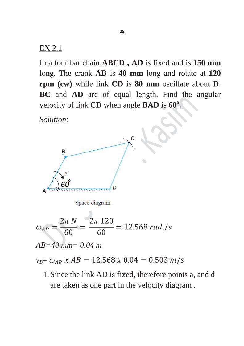
In a four bar chain ABCD , AD is fixed and is 150 mm long. The crank AB is 40 mm long and rotate at 120 rpm (cw) while link CD is 80 mm oscillate about D. BC and AD are of equal length. Find the angular velocity of link CD when angle BAD is 60o.
Solution:
AB=40 mm= 0.04 m
vB=
1. Since the link AD is fixed, therefore points a, and d are taken as one part in the velocity diagram .
26
2. Draw vector ab AB (to some suitable scale in this case) the scale is 1 m= 100 mm, so to represent vB=0.503 m/s the vector should be (5.03 cm).
3. From point b draw bc CB. 4. From point d draw dc CD, so bc and dc will
intersect at point c. 5. By measuring dc is = 38.5 mm
So, vc= And
= = 4.8 rad/s
27
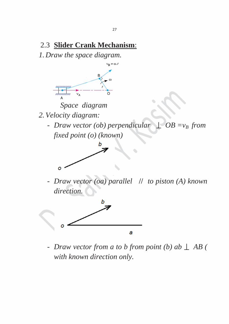
2.3 Slider Crank Mechanism: 1. Draw the space diagram.
Space diagram
2. Velocity diagram: - Draw vector (ob) perpendicular OB =vB from
fixed point (o) (known)
- Draw vector (oa) parallel // to piston (A) known
direction.
- Draw vector from a to b from point (b) ab AB (
with known direction only.
28
- The intersect of these to line gives point(a).
Then vA can be measured.
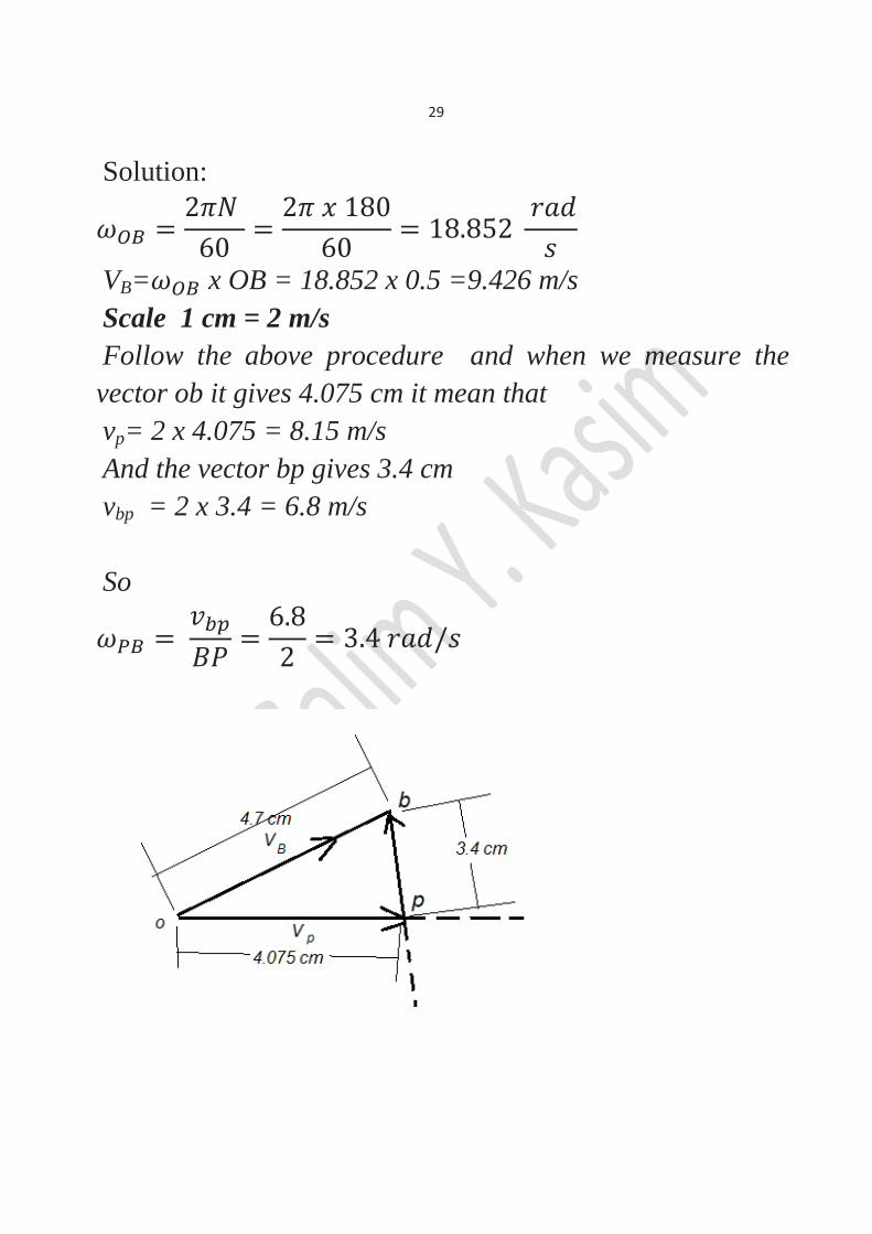
Ex 2.2 The crank and connecting rod of a theoretical steam engine are 0.5 m and 2 m long respectively. The crank makes 180 rpm in the cw direction when it has turned 45o from the inner dead center position . determine the velocity of the piston and the angular velocity of the connecting rod.
Space diagram
29
Solution:
VB= x OB = 18.852 x 0.5 =9.426 m/s Scale 1 cm = 2 m/s Follow the above procedure and when we measure the vector ob it gives 4.075 cm it mean that vp= 2 x 4.075 = 8.15 m/s And the vector bp gives 3.4 cm vbp = 2 x 3.4 = 6.8 m/s So
30
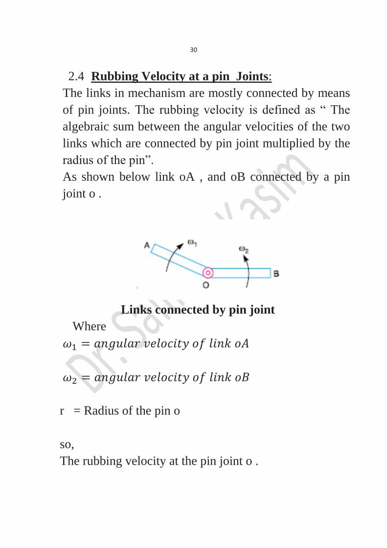
2.4 Rubbing Velocity at a pin Joints: The links in mechanism are mostly connected by means of pin joints. The rubbing velocity is defined as “ The algebraic sum between the angular velocities of the two links which are connected by pin joint multiplied by the radius of the pin”. As shown below link oA , and oB connected by a pin joint o .
Links connected by pin joint
Where
r = Radius of the pin o so, The rubbing velocity at the pin joint o .
31
vRub= ( vRub= ( opposite direction. Note: When the pin connects one sliding member and the other turning member then the angular velocity of the sliding member is Zero in such case vRub=
32
Ex 2.3: For Ex 2.2 find the rubbing velocities at the pins of the crank shaft, crank, and cross head when the pins diameters are 50 mm, 60 mm, and 30 mm respectively. Solution:
2.4 Velocity diagram for a block sliding on a rotating link:
Let be the angular velocity of the link OB, A is a block sliding on the link and has absolute velocity va as shown in figure below where va assumed to be known in magnitude
33
and direction Ᾱ is the point on the link coincident with the block.
= O The block A has velocity relative to and is parallel to O
34
3.Acceleration in Mechanism: We have discussed the velocity diagram of various points
in the previous chapter . The acceleration will be discuss in this chapter.
3.1 Acceleration Diagram for a link:
Consider two points A and B on a rigid link as shown in figure below in which point B moves with respect to A, with an angular velocity , and let be the angular acceleration of the link AB.
To Draw the acceleration diagram the following steps to be follow:
35
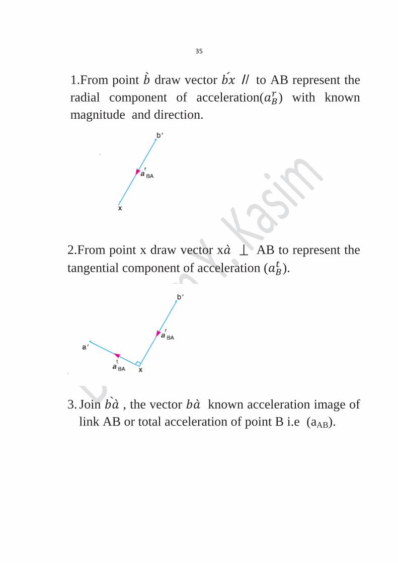
1.From point draw vector ̸̸̸ ̸ to AB represent the radial component of acceleration( ) with known magnitude and direction.
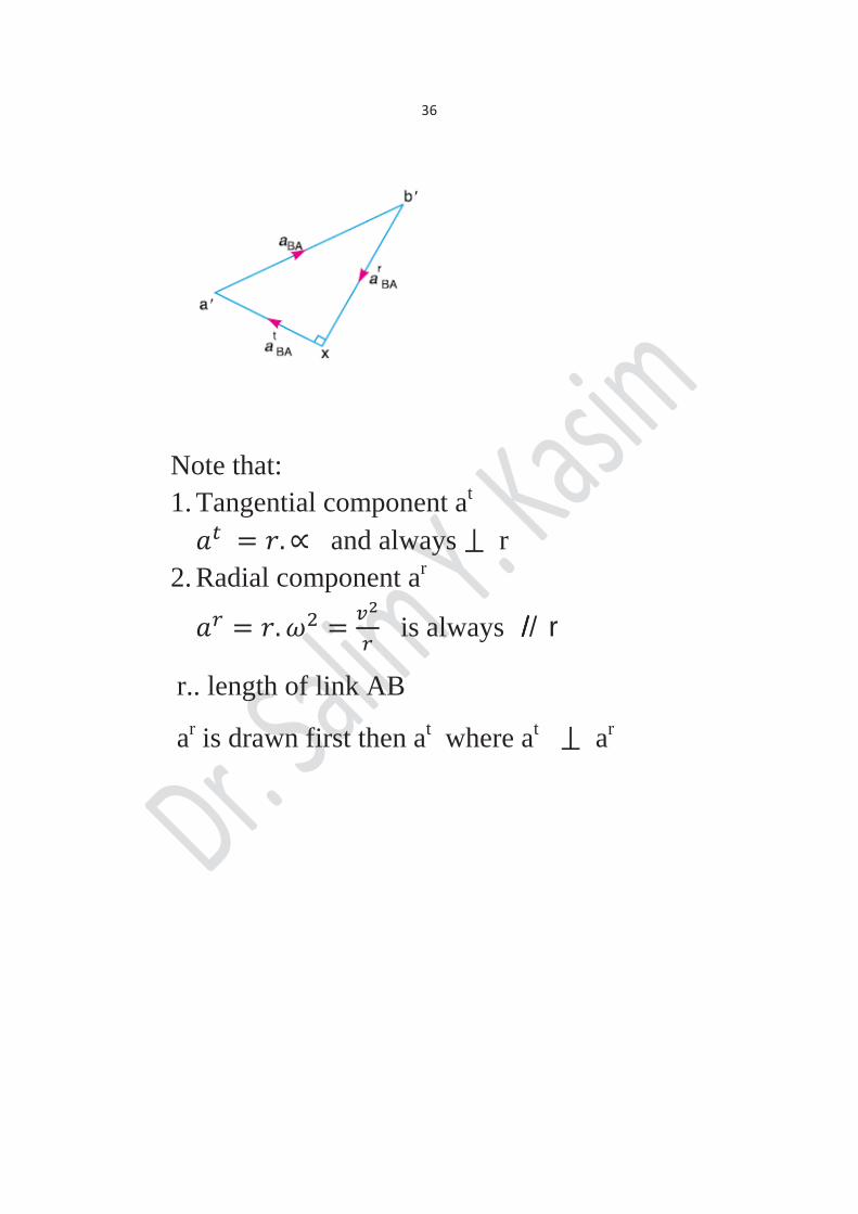
2.From point x draw vector x AB to represent the tangential component of acceleration ( ).
3. Join , the vector known acceleration image of link AB or total acceleration of point B i.e (aAB).
36
Note that: 1. Tangential component at
and always r 2. Radial component ar
is always ̸̸̸ ̸ r
r.. length of link AB
ar is drawn first then at where at ar
37
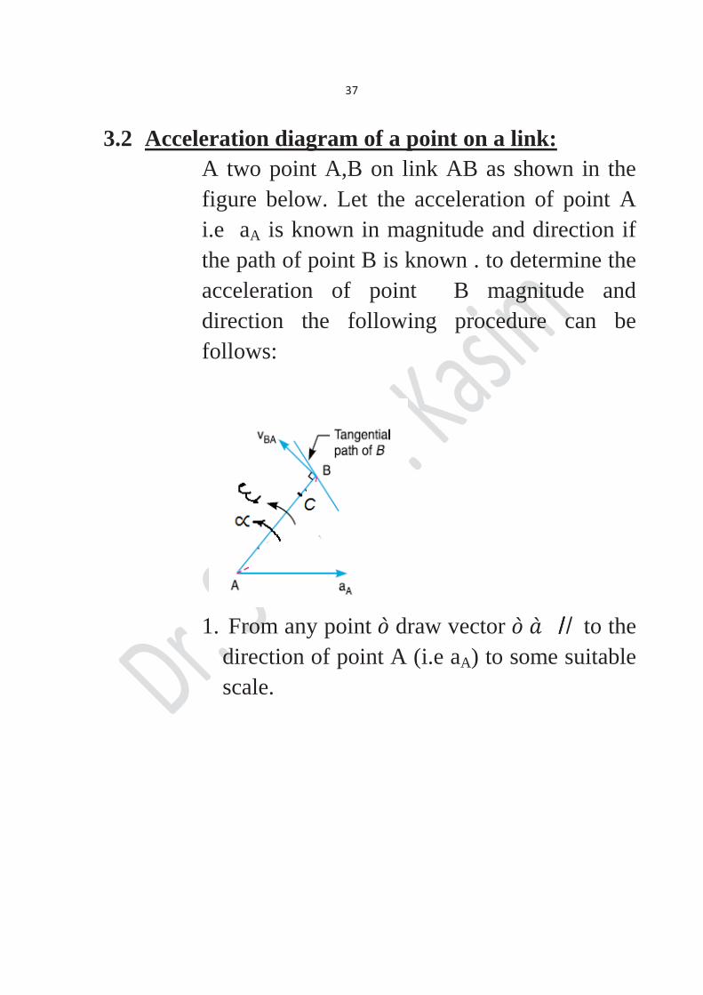
3.2 Acceleration diagram of a point on a link: A two point A,B on link AB as shown in the figure below. Let the acceleration of point A i.e aA is known in magnitude and direction if the path of point B is known . to determine the acceleration of point B magnitude and direction the following procedure can be follows:
1. From any point draw vector ̸̸̸ ̸ to the
direction of point A (i.e aA) to some suitable scale.
38
2. Draw vector x ̸̸̸ ̸ to AB which represent
( ) and = or With the same scale.
3. From point x draw vector x to x 4. From draw line ̸̸̸ ̸ to path B 5. Now the vectors x and will intersect at
point , and the values of aB and can be measured to the scale.
6. Join and the acceleration image of link AB will represented by vector .
7. The acceleration of any point (c) on AB may be obtained by
= aCA and c = ac
8. The value of angular acceleration then
can be obtained by =
39
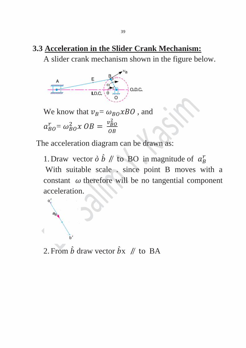
3.3 Acceleration in the Slider Crank Mechanism: A slider crank mechanism shown in the figure below.
We know that = , and
=
The acceleration diagram can be drawn as:
1. Draw vector BO in magnitude of With suitable scale . since point B moves with a constant therefore will be no tangential component acceleration.
2. From draw vector x BA
40
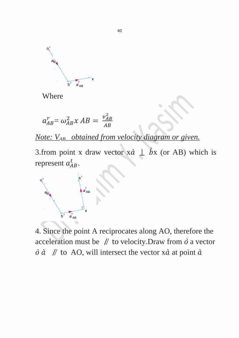
Where
=
Note: VAB obtained from velocity diagram or given.
3.from point x draw vector x x (or AB) which is represent .
4. Since the point A reciprocates along AO, therefore the acceleration must be velocity.Draw from a vector
AO, will intersect the vector x at point
41
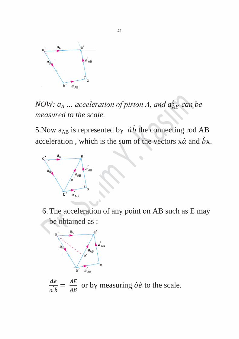
NOW: aA … acceleration of piston A, and can be measured to the scale.
5.Now aAB is represented by the connecting rod AB acceleration , which is the sum of the vectors x and x.
6. The acceleration of any point on AB such as E may
be obtained as :
or by measuring to the scale.
42
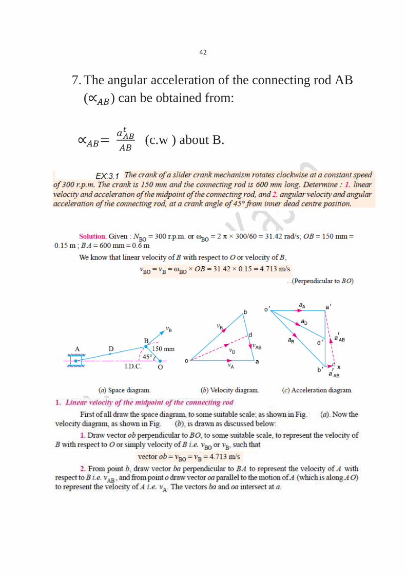
7. The angular acceleration of the connecting rod AB ( ) can be obtained from:
(c.w ) about B.
43
44
45
46
3.3 Coriolis Component of Acceleration:
When a point on one link is sliding along another rotating link, such as in quick return motion mechanism as shown in the figure below, then the coriolis component can be calculated as:


![Measuring Angles. Geometry vs Algebra Segments are Congruent –Symbol [ ] –AB CD – 1 2 Lengths of segments are equal. –Symbol [ = ] –AB = CD.](https://static.documents.pub/doc/80x56/56649f145503460f94c29774/measuring-angles-geometry-vs-algebra-segments-are-congruent-symbol-.jpg)

